user guide...2e.repeat step 2d using the other vertical frame. after all the frame pieces are joined...
TRANSCRIPT

User Guide
LED Thin FrameFixed Frame Screen

WARNING - Sharp EdgesThis product may contain sharp edges, please handle with care. Protective gloves are rec-ommended.
1
INTRODUCTION
Disclaimer: We are not responsible for any direct or indirect damage to property or life related to our product.
Screen Material HandlingThe projection screen material is a special engineered optical fabric for projection use only. Do not use this screen material for other purposes.Do not touch this screen material with your bare hands.Do not fold the material or maneuver the material in other ways not described in this manual.Do not use alcohol, abrasive, or other chemical cleaning solutions on the material.Do not use any adhesive tape directly on the material.Do not use any tools or sharp objects against the screen material.Do not press the screen material against any hard surfaces.We will not be responsible for any damage to the screen caused by false handling.
Avoid using sharp objects around the screen material and roller.
Do not lay the roller directly onto the ground for a long period of time
WARNING - Electrical HazardThis product contains electrical components. Do not assemble, install, or service this prod-uct when there is power connected.
INTRODUCTION
WARNING - Heavy ObjectSeek assistance in installing this product if necessary.
WARNING - Pinch PointDuring assembly, keep hands clear between joining parts.
WARNING - Do Not TouchAvoid touching the optical surface or view-able area of the projection screen at all times.
2

Features 3 Getting Started Parts Included 4 General Dimensions 5 Projection Setup 5 Assembly Before You Start 6 Unpacking 7 Aluminum Frame 8 Screen Fabric 14 Velvet Cover 23 LED Lighting Kit 24 Installation Hanging Brackets 27 Before Hanging Your Screen 27 Hanging Your Screen 29 Maintenance Guide General Notes 31 Cleaning Guide 32 Troubleshooting 33
The LED Thin Frame fixed frame screen features include:
-Modern thin frame design with black velvet border.-Spring mount design ensures an even distribution of tension across fabric to avoid wrinkles on the screen surface.-High strength aluminum frames for long term durability.
The LED Thin Frame fixed frame screen projection material features a high gain, high contrast, and extra pop for your image. It also provide excellent ambient light rejecting ability for use in bright environments.
3
INTRODUCTION
Features
Table of Contents This guide will lead you through detailed steps on how to correctly and safely assemble and install your screen. Please follow the steps as instruct-ed. If you need assistance, please see the Troubleshooting section.
Check the parts and accessories inside the packaging to make sure none are missing.
Aluminum Inner Frame
2 long pcs4 short pcs
Aluminum Velvet Cover
2 long pcs4 short pcs
Plastic Rods2 long pcs4 short pcs
GETTING STARTED
Parts Included
Springs(Amount differs on size)
Corner Brackets8pcs
Expansion Plugs(Amount differs on size)
Hanging Brackets(Amount differs on size)
Set Screws (Amount differs on size)
LED Connectors3pcs
Bracket Screws(Amount differs on size)
Support Bar (1pc for select sizes)
And related accessories
Screen Fabric (With Floor Cloth)
1 Roll
Installation Hook2pcs
4
LED Control Box1pc
The following items will be included in the Accessories Box:
Joint Brackets4pcs
Mounting Plates2pcs
Your screen comes with an RF remote. The IR control kit is optional.
A Support Bar is included for screen sizes over 120” 16:9 and on select 2.35:1 sizes.

Please make sure there is sufficient space for the screen to hang on the wall or other preferred location. Refer to the table below for screen sizes.
ScreenSize
Aspect Ratio Assembled Width
Assembled Height
Assembled Depth
92” 16:9 81” 46” 2”
100” 16:9 88” 50” 2”
110” 16:9 97” 55” 2”
120” 16:9 106” 60” 2”
120” 2.35:1 112” 48” 2”
133” 2.35:1 124” 53” 2”
GETTING STARTED
General Dimensions
Projection SetupThe LED Thin Frame fixed frame screen is designed for front projection. Make sure you are using the correct projection method. The screen materi-al is an ambient light rejecting material with angular reflective properties. For best performance, angle the projector so the reflection angle lines up with the view as shown in the diagram below:
The distance required between the projection screen and the projector de-pends your projector. Please refer to your projector’s manual or technical specifications for more details.
5We recommend the projector be mounted onto the ceiling and the screen against a flat wall. If your wall is not flat, please see Page 27.
ASSEMBLYYou are now ready to assemble your screen. There are 3 major parts of the screen that need to be assembled: Aluminum Frame, Screen Fabric, and Velvet Cover. Please go through the following steps one by one carefully.
Before You StartYou will be assembling the screen on a flat ground. You will need a clearance area of at least two feet away from the screen (refer to General Dimensions). Make sure no objects are underneath the screen as they may cause permanent damage to the fabric.
Before you start handling parts, you need to make sure your work area is safe, and remains safe during assembly and installation. Please note and be aware of the following:
Parts may contains sharp edges. Avoid touching the indicated spots. Do not swing the aluminum frames; be aware of the edges when you handle the frames. Pro-tective gloves are recommended.
Beware of pinching point.Be cautious joining pieces together when this icon is present. Keep body parts away from the indicated spots. Protective gloves are recommended.
Tools required.Additional tools which are not included are needed for this step. Incorrect tools may cause damage to the hardware.
Special attention needed.Please refer to the description whenever this icon present. De-tailed instructions are in the description which are not present in the diagram.
Assembling the screen requires two people. We recommend you and your partner to work together to assemble the screen. Seek assistance when handling heavy objects or hanging the screen.
6
ASSEMBLY
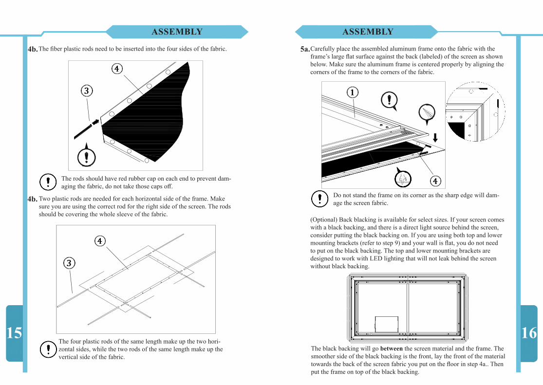
The Inner Frame is the first part to be assembled. Make sure to lay out the Inner Frames across a flat ground as shown below.
Insert the two of Joint Brackets into the slots of the two horizontal frame pieces. Position the brackets so they are centered, insert the Set Screws, and do not tighten the set screws as shown below.
1c.
1d.
7
Floor Cloth
Horizontal Frame
Vertical Frame
ASSEMBLY
Floor Cloth
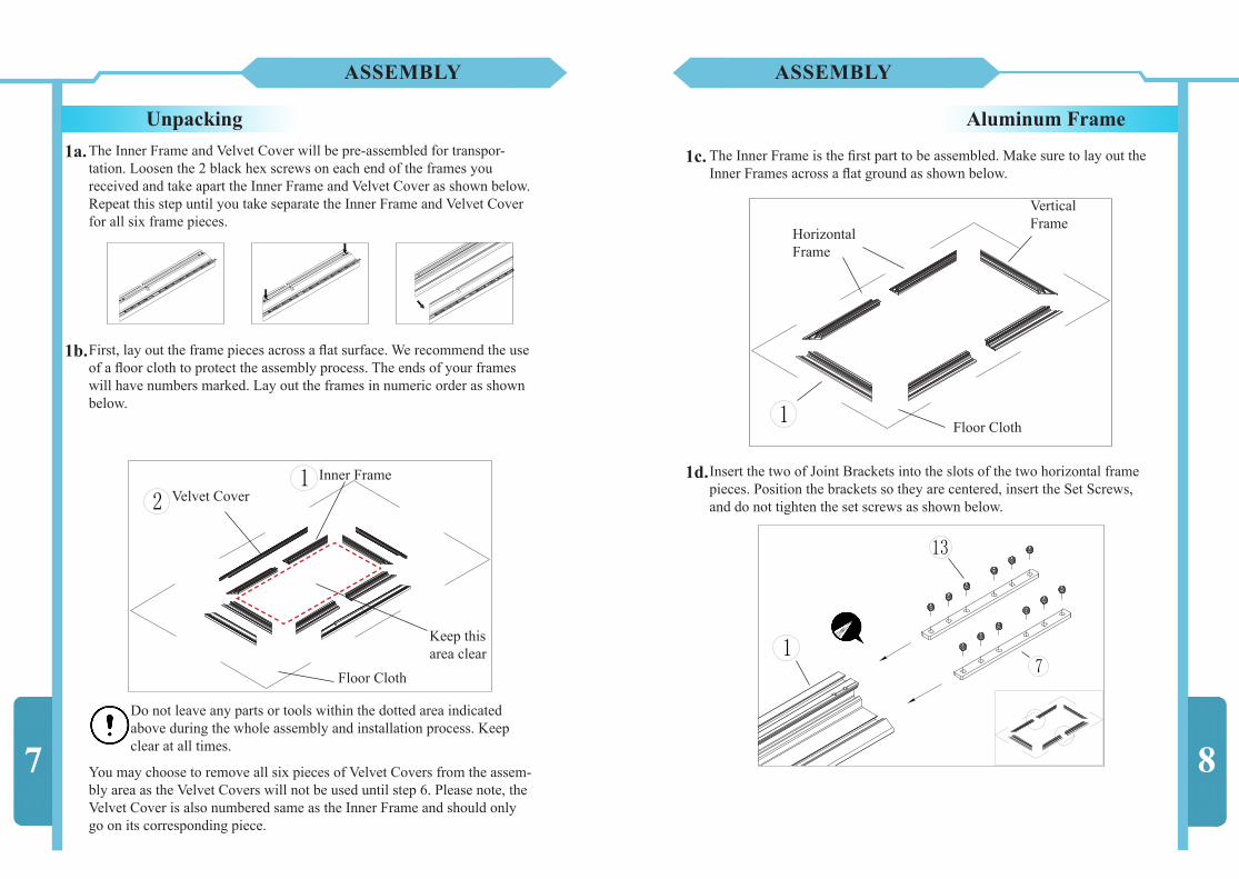
Velvet CoverInner Frame
Unpacking
First, lay out the frame pieces across a flat surface. We recommend the use of a floor cloth to protect the assembly process. The ends of your frames will have numbers marked. Lay out the frames in numeric order as shown below.
1b.
8
The Inner Frame and Velvet Cover will be pre-assembled for transpor-tation. Loosen the 2 black hex screws on each end of the frames you received and take apart the Inner Frame and Velvet Cover as shown below.Repeat this step until you take separate the Inner Frame and Velvet Cover for all six frame pieces.
1a.
Aluminum Frame
Keep this area clear
Do not leave any parts or tools within the dotted area indicated above during the whole assembly and installation process. Keep clear at all times.
You may choose to remove all six pieces of Velvet Covers from the assem-bly area as the Velvet Covers will not be used until step 6. Please note, the Velvet Cover is also numbered same as the Inner Frame and should only go on its corresponding piece.

ASSEMBLY
Insert two Corner Brackets into the slots on each sides of the vertical frame. Position the brackets so they are centered, insert the Set Screws, and do not tighten the set screws as shown below.
The screen should now be as shown below. The Inner Frame pieces can now be joined together with the brackets from previous steps.
9
1f.
1e. Starting with the horizontal frames, insert the Joint Brackets into the other horizontal frame, then push two horizontal frame pieces together. Make sure there is no gap, then tighten the Set Screws.
2a.
ASSEMBLY
(Optional) On select large sized screens only, you will be provided with a middle Support Bar. If you have a Support Bar, lay out the Support Bar as shown below.
2b.
10

Insert the Corner Brackets into the vertical frame and the horizontal frame. Align the corner and push the two frames towards the corner. Make sure there is no gap bigger than 1mm, then tighten the Set Screws. If you have a Support Bar, see 2e.
2d.
Make sure you align both sides properly and center the bracket inside its slot before tightening the Set Screws on either sides.
11
ASSEMBLY
(Optional) Insert both ends of the support bar into the middle of the hori-zontal frames until snug.
2c.
12
ASSEMBLY
Repeat step 2d using the other vertical frame.2e.
After all the frame pieces are joined together, it will look similar to below. Check and tighten all Set Screws as they will not be able to accessible once the Outer Frame is installed.
2f.
Make sure the corners are at 90 degree angles and that the hori-zontal frames are straight before proceeding. There should be no gap between the horizontal frames and less than 1mm gap in the four corners.

13You want to position the LED Control Box that the cable coming out of the control box is able to go through the slot on the frame and reach the LED strips.
Take out the LED Control Box from its packaging and place it on the frame as shown below. There will be two pre-installed support anchors in the frame.
3a.
Slide the anchors into the proper position. Insert the screws and mount the LED Control Box as shown below. Mount the box the furthest to the back of the frame as possible, align the screws, then tighten them.
ASSEMBLY
3b.
Screen Fabric
Next, the screen material needs to be unrolled and mounted onto the frame assembled in the previous steps.
Make sure the ground is clear of any sharp obstacles and make sure there is a floor cloth covering the ground. Do not remove the floor cloth until the assembly is completed. The floor cloth will protect the fabric screen against dirt or other particles from the ground.
Floor Cloth Fabric Screen(Facing Down)
14
ASSEMBLY
Unroll the fabric screen slowly from the cardboard drum onto the ground. The front of the fabric should be facing the ground, and the back facing upwards. There will be a label indicating the back of the fabric. In case the label is removed from the screen material, the matte, smoother ,and finer side of the screen material is the front. If your material is a weave, the tighter weave pattern side is the front.
4a.
Wear protective gloves to prevent scratches or other damages may occur on the fabric. Make sure the ground is free of sharp objects and do not put any tools or other objects onto the fabric.
4b.
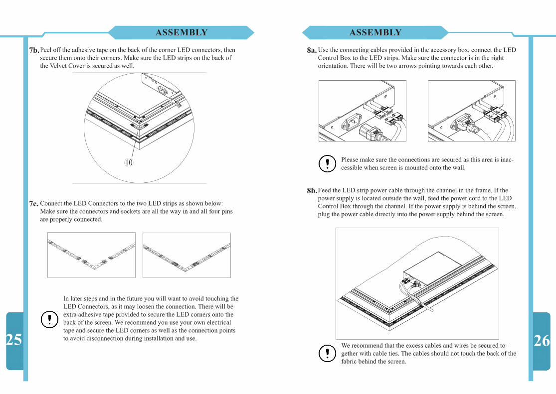
The fiber plastic rods need to be inserted into the four sides of the fabric.
The rods should have red rubber cap on each end to prevent dam-aging the fabric, do not take those caps off.
ASSEMBLY
Two plastic rods are needed for each horizontal side of the frame. Make sure you are using the correct rod for the right side of the screen. The rods should be covering the whole sleeve of the fabric.
The four plastic rods of the same length make up the two hori-zontal sides, while the two rods of the same length make up the vertical side of the fabric.
15
4b.
4b.
ASSEMBLY
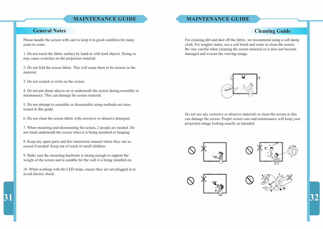
Carefully place the assembled aluminum frame onto the fabric with the frame’s large flat surface against the back (labeled) of the screen as shown below. Make sure the aluminum frame is centered properly by aligning the corners of the frame to the corners of the fabric.
Do not stand the frame on its corner as the sharp edge will dam-age the screen fabric.
5a.
16
(Optional) Back blacking is available for select sizes. If your screen comes with a black backing, and there is a direct light source behind the screen, consider putting the black backing on. If you are using both top and lower mounting brackets (refer to step 9) and your wall is flat, you do not need to put on the black backing. The top and lower mounting brackets are designed to work with LED lighting that will not leak behind the screen without black backing.
The black backing will go between the screen material and the frame. The smoother side of the black backing is the front, lay the front of the material towards the back of the screen fabric you put on the floor in step 4a.. Then put the frame on top of the black backing.

ASSEMBLY
Flip over the sides of the fabric with plastic rods onto the edges of the aluminum frame, as illustrated below.
The fabric and the frame will be joined with springs. First the corners will be secured, then the sides will be secured starting from the corners and moving towards the middle. The shorter sides should be secured first for optimal tension. The priority that the springs should be secured is below.
5b.
5c.
17
1 1
11
2
2
3 3
2
2
33
Pick a corner to start working at. Mount 4 springs in the 4 holes that are closest to the corner starting with the vertical side (2). Repeat with all 4 corners.
Use the installation hook provided to mount the springs. Latch the shorter hook onto the lip of the frame. Carefully pull the larger hook through the hole in the screen and around the plastic rod. Make sure that the spring is only around the rod and not caught on any fabric before you release it.
ASSEMBLY
5d.
5e.
18

Repeat step e) until you have mounted every hole in the fabric with a spring, in a sequence shown in c).
Follow the sequence indicated above in c) to minimize the unnec-essary stress to the screen fabric.
You want to execute step e) with extra caution. When you let go of the spring, you need to make sure the spring is only lying on the plastic rod, otherwise the spring will tear through the fabric.
After completing step f), you can now stand the screen up on its side as shown on the left. Make sure the ground is free of obstacles and rough objects before you do so. We recommend to stand the screen on a soft cushion in addition to the floor cloth we provided to prevent damage to the screen as well as the flooring.
Do not slide or drag the screen across the floor.
Have one person hold the screen upright by the aluminum frame on the back and not by the fabric. Carefully inspect the front of the screen fabric. The fabric must wrap around the Aluminum Frame so that the sleeve of the fabric will not be shown over the 1/2” outer frame.
5f.
5g.
To eliminate the wrinkles on the screen, more material needs to be wrapped around the frame for the springs to hold onto. This will tighten the screen fabric and get rid of the wrinkles in the process. This process has to be done manu-ally and the procedure is outlined below.
ASSEMBLY
19The below steps requires the use of tools or your hands to pull directly on the fabric, exercise with caution. Do not pull on the fabric using other methods or tools not described below.
ASSEMBLY
Pull the Installation Hook towards back of the frame. This will stretch and wrap the screen fabric around the frame.
Repeat the above steps for other springs near the wrinkles. Repeat as nec-essary until there are no more wrinkles in the screen fabric. If necessary, you may also use your hands for this operation described above. Please wear protective gloves and only pull on the sleeve of the fabric.
Locate the wrinkles on the screen and the springs that are near them. Start from the spring closest to the wrinkle and insert the Installation Hook directly into the fabric sleeve. Make sure the installation hook is over the fiber plastic rod and not the springs or the fabric alone. Pull the spring upwards and away from the frame.
20If your screen still has wrinkles or more tension is required, repeat the above method and pull on the fabric harder until you have reached a desired effect.

Check your corners before proceeding. If there are any wrinkles on the corners, you need to tension the fabric more so that the corners will be flat.
5h.
Repeat step 5g. Remove the springs around the corners and move the ma-terial towards the corner as shown below. Remount the springs and pull on the fabric manually as described above to get rid of wrinkles in the corner of the fabric.
21
ASSEMBLY
Pull on the fabric and wrap the fabric around the corner until the corner is flat and free of wrinkles. You may use your hands for this operation. Please wear protective gloves and only pull on the sleeve of the fabric. 22
ASSEMBLY
At each of the corners of the screen material there will be a flap of material with Velcro attached facing upwards. Cut off the excess Velcro so that 1/4” of the Velcro is left between the frame and the material at the corner as indicated by the arrow below:
5i.
Flip the flap of material over and stick the Velcro towards the frame as shown below:
14"
You may need to pull on the flap and flip over to create tension on the corner to eliminate screen material wrinkles.

ASSEMBLY
Velvet CoverOnce the screen fabric is in an acceptable condition, the aluminum velvet covers can be assembled. Lay the Velvet Covers around your screen matching their numbers with the aluminum frame numbers.
6a.
Slide the long Velvet Cover onto the border of the frame with the same length. Lift the corresponding border a tiny bit (1/4”) off the ground and slide the Velvet Cover onto the border with its long side facing up as shown below.
Make sure the Aluminum Velvet Cover you are trying to put on is marked the same number according to the Inner Frame.
6b.
23
ASSEMBLY
After mounting all the Velvet Covers, tighten the Set Screws on the ends of each Velvet Covers, as shown below. Make sure there are no gaps in between the Velvet Covers before tightening the Set Screws.
7a. The LED Lighting Kit is now ready to be installed onto your screen.Three LED Connectors need to be installed onto 3 out of the 4 corners on the screen’s Velvet Cover.
24
LED Lighting Kit
6c.
The corner furthest away from the LED Control Box is the corner that does not require a LED Connector.
In later steps and in the future you will want to avoid touching the LED Connectors, as it may loosen the connection. There will be extra adhesive tape provided to secure the LED corners onto the back of the screen. We recommend you use your own electrical tape and secure the LED corners as well as the connection points to avoid disconnection during installation and use.
ASSEMBLY
25
Peel off the adhesive tape on the back of the corner LED connectors, then secure them onto their corners. Make sure the LED strips on the back of the Velvet Cover is secured as well.
7b.
7c. Connect the LED Connectors to the two LED strips as shown below:Make sure the connectors and sockets are all the way in and all four pins are properly connected.
26
Use the connecting cables provided in the accessory box, connect the LED Control Box to the LED strips. Make sure the connector is in the right orientation. There will be two arrows pointing towards each other.
8a.
Feed the LED strip power cable through the channel in the frame. If the power supply is located outside the wall, feed the power cord to the LED Control Box through the channel. If the power supply is behind the screen, plug the power cable directly into the power supply behind the screen.
8b.
Please make sure the connections are secured as this area is inac-cessible when screen is mounted onto the wall.
ASSEMBLY
We recommend that the excess cables and wires be secured to-gether with cable ties. The cables should not touch the back of the fabric behind the screen.

INSTALLATION
Hanging Brackets
To mount the screen to the wall, the location of the 4 edges need to be determined. For screen specs, please refer to General Dimensions (page 4).
9.
Draw a center line for your screen in the desired location. Mount the Hanging Bracket centered to your screen and 4 1/2” (116mm) from the top of the screen. Next, mount two pairs of Mounting Plates 4 1/2” (116mm) above the bottom, and 8” from the sides of the screen as shown above.
27
You are now ready to mount your screen. Please make sure your screen is fully assembled before proceed.
Before Hanging the ScreenThe top two corners of the screen may be sharp as circled in the diagram below. It is recommended to use masking tape to cover the sharp area that could potentially damage your wall when hanging your screen.
Please make sure the wall you are mounting your screen to is able to support the weight of the screen. We recommend using your own hardware for the installation. If using the hardware supplied, (Wall Screws and Expansion Plug) ensure that it is compatible with the wall.
The Hanging Bracket is designed to bear the weight of the entire screen, make sure the bracket is sturdy before mounting the screen.
The Mounting Plates are designed to hold the screen flush against the wall with the use of magnets on the screen. Move the Mount-ing Magnets on the back of the frame to a location coordinated to the Mounting Plates on the wall before hanging the screen.
INSTALLATION
28

INSTALLATION
Hanging Your ScreenThe screen is now ready to be mounted onto the wall. The upper frame of the screen needs to be lowered onto the Hanging Bracket, as shown below.
29
Please make sure the screen’s top frame is properly anchored in the Mounting Bracket before letting go of the screen.
The screen needs to be stood up vertically on the floor. Two people are necessary to carry and lift the screen up onto the brackets.
10.
INSTALLATION
30
If your wall is not flat, you need to adjust the height of the Mounting Bracket or the Mounting Plates, as shown below:
As illustrated above and below, use washers provided in the packaging underneath the Mounting Brackets or Mounting Plates to make the screen sitting upright when the wall is not completely flat.
Now, you are ready to enjoy the superb performance of LED Thin Frame fixed frame screen.
MAINTENANCE GUIDE
Please handle the screen with care to keep it in good condition for many years to come.
1. Do not touch the fabric surface by hand or with hard objects. Doing so may cause scratches on the projection material.
2. Do not fold the screen fabric. This will cause there to be creases in the material.
3. Do not scratch or write on the screen.
4. Do not put sharp objects on or underneath the screen during assembly or maintenance. This can damage the screen material.
5. Do not attempt to assemble or disassemble using methods not men-tioned in this guide.
6. Do not clean the screen fabric with corrosive or abrasive detergent. 7. When mounting and dismounting the screen, 2 people are needed. Do not stand underneath the screen when it is being mounted or hanging. 8. Keep any spare parts and this instruction manual where they can ac-cessed if needed. Keep out of reach of small children.
9. Make sure the mounting hardware is strong enough to support the weight of the screen and is suitable for the wall it is being installed on.
10. When working with the LED strips, ensure they are not plugged in to avoid electric shock.
General NotesFor cleaning dirt and dust off the fabric, we recommend using a soft damp cloth. For tougher stains, use a soft brush and water to clean the screen. Be very careful when cleaning the screen material so it does not become damaged and worsen the viewing image.
Cleaning Guide
31 32
Do not use any corrosive or abrasive materials to clean the screen as this can damage the screen. Proper screen care and maintenance will keep your projection image looking exactly as intended.
MAINTENANCE GUIDE

33
TROUBLESHOOTING
6. The corners of the screen material are wrinkled.Solution: This is a common user error when the frame is jammed against the material when installing on the ground. You can easily eliminate the wrinkles by using the flaps at each corners of the screen material. Go back to steps 5h and 5i, take out the outer frame, then tension the corners. You do not need a lot of tension to make the corners flat. Lift the screen from the ground and put the outer frame onto the screen. Make sure to give the outer frame enough clearance off the ground until it is in place.
7. My screen’s LED lighting does not light up, or partially lights up.Solution: Check your connections as the LED strips can be easily discon-nected when hanging your screen. Thus, it is recommended to use insulat-ing tape to wrap around the connecting areas without blocking the LED bulb. This way the connection will be secured. If 2 sides of your LED strips do not light up at all or it lights up in a dim red color, you need to flip the connectors in step 8a. The diagram on the left shows the two LED connectors. Flip the connector 180 degrees of the LED strip does not light up properly and connect to the LED control box.
8. I am putting the screen’s power plug behind the screen, but the plug created a bulge on the screen.Solution: It is recommended to use a recessed power outlet plate behind the screen to give you more clearance. If you need a different kind of power cable, consider purchasing another C13/C14 computer power plug for your application. If you have excess cables behind your screen causing it to bulge up, consider tying the cable and secure them to the frame.
9. The Velcro at the corners of the fabric is too thick, I could put on and close the screen’s outer frame.Solution: Go back to step 5i and consider cutting the Velcro shorter. If you still have difficulty putting the frame on, consider trimming the flaps of material at the corners thinner.
34
1. I am missing parts from my packaging. Solution: The Fiber Plastic Rods may be stored inside the roll of Screen Fabric. Check if your missing parts are already pre-installed onto the screen. If you still have parts missing, contact customer support.
2. My screen fabric is damaged when I open the package. Solution: In case of damaged or defective product, please contact your vendor or customer support right away.
3. It is very difficult to pull the springs. Solution: Make sure you are using the correct methods. Seek assistance if needed, careless operation may risk damaging the screen.
4. I see the sleeve of the fabric shown over the Velvet Cover of the screen after I fully assembled it.Solution: The Velvet Covers have to be dismounted and then repeat steps 4-6 (Assembly - Fabric Screen). Make sure the screen fabric is not shifted, and the evenly distribute the fabric across the frame. Inspect the screen fabric before installing the Velvet Covers.
5. I see wrinkles and lines on the screen projection surface.Solution: If you just installed this screen, and you see lines or wrinkles on the screen surface, do not panic! The screen material is a flexible pro-jection material and depending on how the screen material is handled or installed, the screen may have wrinkles. With proper adjustments they will disappear.
Check the tension of the screen material, and smooth out the material evenly along the side of the Plastic Rod holding the screen. Go through step 5g and make sure there is sufficient tension on the screen. If done properly, you should have very few to no wrinkles on the screen. Consider leaving your screen in a warm environment for up to few weeks which will allow the fabric to relax and flatten itself overtime. Install the screen on the wall properly before doing so; do not lean the screen against other objects or leaving it on the ground. If you still have wrinkles over a few weeks or if you have any concerns, consider contact customer support.
TROUBLESHOOTING
