user guide and demo application - lsr software reset is being used for the demo application...
TRANSCRIPT

The information in this document is subject to change without notice. 330-0057-R2.0 Copyright © 2010-2012 LS Research, LLC Page 1 of 15
MODFLEX SHIELD FOR ARDUINO USER GUIDE AND DEMO APPLICATION
Last updated March 20th, 2012

ModFLEX SHIELD FOR ARDUINO USER GUIDE AND DEMO APPLICATION
The information in this document is subject to change without notice. 330-0057-R2.0 Copyright © 2010-2012 LS Research, LLC Page 2 of 15
Table of Contents 1 Introduction ................................................................................................................... 3
1.1 Purpose & Scope ....................................................................................................................... 3 1.2 Applicable Documents ............................................................................................................... 3 1.3 Revision History ......................................................................................................................... 3
2 Jumper Configurations ................................................................................................. 4
3 Firmware and Necessary Software .............................................................................. 5
3.1 Arduino Software ....................................................................................................................... 5
4 Demo Application .......................................................................................................... 9
5 Ping Pong Range Test on ModFLEX Shield .............................................................. 14
6 Contacting LS Research ............................................................................................. 15
ModFLEX SHIELD FOR ARDUINO USER GUIDE AND DEMO APPLICATION
The information in this document is subject to change without notice. 330-0057-R2.0 Copyright © 2010-2012 LS Research, LLC Page 3 of 15
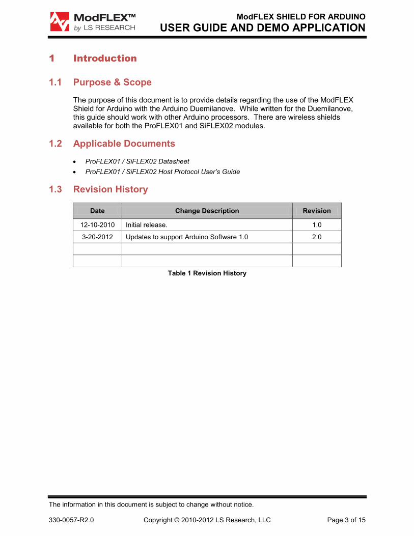
1 Introduction
1.1 Purpose & Scope
The purpose of this document is to provide details regarding the use of the ModFLEX Shield for Arduino with the Arduino Duemilanove. While written for the Duemilanove, this guide should work with other Arduino processors. There are wireless shields available for both the ProFLEX01 and SiFLEX02 modules.
1.2 Applicable Documents
• ProFLEX01 / SiFLEX02 Datasheet • ProFLEX01 / SiFLEX02 Host Protocol User’s Guide
1.3 Revision History
Date Change Description Revision
12-10-2010 Initial release. 1.0
3-20-2012 Updates to support Arduino Software 1.0 2.0
Table 1 Revision History

ModFLEX SHIELD FOR ARDUINO USER GUIDE AND DEMO APPLICATION
The information in this document is subject to change without notice. 330-0057-R2.0 Copyright © 2010-2012 LS Research, LLC Page 4 of 15
2 Jumper Configurations
2.1.1 Jumper 1 (J1)
Jumper J1 is used to enable the software reset for the ModFLEX module. When this is enabled (moved to the position connecting pins 2 and 3) digital pin 6 (D6) on the Arduino Duemilanove controls the reset signal of the ModFLEX module. When using the software reset capability, D6 on the Duemilanove needs to be configured as a digital output and be set high for normal operation. Resetting the ModFLEX module is accomplished by setting D6 low for a couple of milliseconds, and then setting it back high.
The software reset is being used for the demo application provided, and as such J1 pins 2 and 3 should be jumpered.
2.1.2 Jumper 2 and 3 (J2 and J3)
J2 and J3 are responsible for determining which mode of UART the Duemilanove uses to communicate with the ModFLEX module on the ModFLEX Shield. When the ModFLEX Shield is configured to use hardware UART mode (J2 and J3 moved to the positions connecting pins 1 and 2) the Duemilanove will use its designated UART RX and TX pins (D0 and D1 respectively) to communicate with the ModFLEX module. When it is desired to use software UART mode, digital pins 7 (D7) and 8 (D8) will be the RX and TX UART signals respectively.
When using hardware UART mode, the J2 and J3 jumpers must be removed when uploading software to the Duemilanove. The reason for this is that the hardware UART is used by the Arduino bootloader.
For the demo application software UART mode is used, and as such jumpers J2 and J3 should be connected between pins 1 and 2.

ModFLEX SHIELD FOR ARDUINO USER GUIDE AND DEMO APPLICATION
The information in this document is subject to change without notice. 330-0057-R2.0 Copyright © 2010-2012 LS Research, LLC Page 5 of 15
3 Firmware and Necessary Software
3.1 Arduino Software
First you will need the Arduino Software. At the time of this writing the most current build is 1.0. It can be downloaded by using this link: http://arduino.cc/en/Main/Software.
Extract the downloaded .zip’s contents anywhere you would like. No installation is required; you will simply locate and execute the arduino.exe file located within the extracted folder to use this software:
Figure 1 Arduino Software

ModFLEX SHIELD FOR ARDUINO USER GUIDE AND DEMO APPLICATION
The information in this document is subject to change without notice. 330-0057-R2.0 Copyright © 2010-2012 LS Research, LLC Page 6 of 15
3.1.1 ModFLEX Wireless Shield Library
Download the ModFLEX Wireless Shield Library from the LSR wiki.
http://wiki.lsr.com/ModFLEX-Arduino.ashx?HL=arduino
Extract the .zip’s contents in the “library” folder located within the extracted “aruindo-1.0” folder:
Figure 2 ModFLEX Shield Library

ModFLEX SHIELD FOR ARDUINO USER GUIDE AND DEMO APPLICATION
The information in this document is subject to change without notice. 330-0057-R2.0 Copyright © 2010-2012 LS Research, LLC Page 7 of 15
If you are using the SiFLEX02 module shield perform the following steps, otherwise skip to Section 3.1.2.
1. Open the newly extracted ModFLEXWireless folder and open the LsrModuleApi.h file using any text editor:
Figure 3 Open API Header File
2. Modify the following #define to SIFLEX02 instead of PROFLEX01:
This can be done by commenting out the PROFLEX01 #define, and un-commenting out the SIFLEX02 #define as shown below.
Figure 4 Configure for SiFLEX02

ModFLEX SHIELD FOR ARDUINO USER GUIDE AND DEMO APPLICATION
The information in this document is subject to change without notice. 330-0057-R2.0 Copyright © 2010-2012 LS Research, LLC Page 8 of 15
3.1.2 Move Sketches
Move the sketches for both the Master and Slave ends of the demo to a project directory. Note that the sketches should not be in the Arduino software directory.
Figure 5 Move Sketches to Project Folder

ModFLEX SHIELD FOR ARDUINO USER GUIDE AND DEMO APPLICATION
The information in this document is subject to change without notice. 330-0057-R2.0 Copyright © 2010-2012 LS Research, LLC Page 9 of 15
4 Demo Application
4.1.1 Purpose
The demo application is provided to show users how the ModFLEX Wireless shield can utilize both a hardware and a software UART on the Arduino, as well as how to make use of the ModFLEX Wireless Library. The Arduino communicates with the ModFLEX module on the shield using a software UART, and with the PC using the hardware UART. Two Arduino Duemilanoves equipped with the same type of ModFLEX Wireless shields (ProFLEX01 or SiFLEX02) are required for this demo application.
4.1.2 Loading the Demo Application
1. Determine which Duemilanove you want to be the “slave” and which one you want to be the “master”.
2. Open the “arduino-1.0” folder and execute the “arduino.exe” file:
Figure 6 Start Arduino Software

ModFLEX SHIELD FOR ARDUINO USER GUIDE AND DEMO APPLICATION
The information in this document is subject to change without notice. 330-0057-R2.0 Copyright © 2010-2012 LS Research, LLC Page 10 of 15
3. First we will load the slave. Locate the “sketch” to be loaded onto the slave. The file is located in the “Slave” folder and is named “slave.ino”.
Figure 7 Open Slave Sketch Step 1
Figure 8 Open Slave Sketch Step 2

ModFLEX SHIELD FOR ARDUINO USER GUIDE AND DEMO APPLICATION
The information in this document is subject to change without notice. 330-0057-R2.0 Copyright © 2010-2012 LS Research, LLC Page 11 of 15
4. If you are using ProFLEX01 ModFLEX shields, edit the following section of code to look like this. This sets the RF output power to a maximum setting of 19, and the RF channel to 15.
Figure 9 Configure Settings for ProFLEX01
Otherwise if you are using SiFLEX02 ModFLEX shields, then edit the following section of code to look like this. This sets the RF output power to a maximum setting of 21, and the RF channel to 5.
Figure 10 Configure Settings for SiFLEX02

ModFLEX SHIELD FOR ARDUINO USER GUIDE AND DEMO APPLICATION
The information in this document is subject to change without notice. 330-0057-R2.0 Copyright © 2010-2012 LS Research, LLC Page 12 of 15
5. Connect the Duemilanove (ModFLEX shield attached) to your PC, make sure the appropriate COM port is selected, and upload to the board:
Figure 11 Select COM Port
6. Download the sketch into the shield.
Figure 12 Download Sketch
7. Repeat the same steps for the master.

ModFLEX SHIELD FOR ARDUINO USER GUIDE AND DEMO APPLICATION
The information in this document is subject to change without notice. 330-0057-R2.0 Copyright © 2010-2012 LS Research, LLC Page 13 of 15
8. At this point both Duemilanoves should be powered up and communicating. Open the Arduino Serial Monitor to see the data the master is sending to the PC using the hardware UART. Make sure the COM port is the same as the one the master is connected to. Also the baud rate should be set to 19,200.
Figure 13 Start Serial Monitor
The Serial Monitor window will appear displaying simple statistics from the master:
Figure 14 Serial Monitor Output

ModFLEX SHIELD FOR ARDUINO USER GUIDE AND DEMO APPLICATION
The information in this document is subject to change without notice. 330-0057-R2.0 Copyright © 2010-2012 LS Research, LLC Page 14 of 15
5 Ping Pong Range Test on ModFLEX Shield
See the Development Kit Quick Start Guide for detailed information regarding the Ping Pong Range Test usage.
The Ping Pong Range Test firmware is built into the module firmware. This allows for the test to be used on the ModFLEX shield. Jumper J1 must be set so the software reset is disabled.

ModFLEX SHIELD FOR ARDUINO USER GUIDE AND DEMO APPLICATION
The information in this document is subject to change without notice. 330-0057-R2.0 Copyright © 2010-2012 LS Research, LLC Page 15 of 15
6 Contacting LS Research
Headquarters LS Research, LLC W66 N220 Commerce Court Cedarburg, WI 53012-2636 USA Tel: 1(262) 375-4400 Fax: 1(262) 375-4248
Website www.lsr.com
Wiki wiki.lsr.com
Technical Support forum.lsr.com
Sales Contact [email protected]
The information in this document is provided in connection with LS Research (hereafter referred to as “LSR”) products. No license, express or implied, by estoppel or otherwise, to any intellectual property right is granted by this document or in connection with the sale of LSR products. EXCEPT AS SET FORTH IN LSR’S TERMS AND CONDITIONS OF SALE LOCATED ON LSR’S WEB SITE, LSR ASSUMES NO LIABILITY WHATSOEVER AND DISCLAIMS ANY EXPRESS, IMPLIED OR STATUTORY WARRANTY RELATING TO ITS PRODUCTS INCLUDING, BUT NOT LIMITED TO, THE IMPLIED WARRANTY OF MERCHANTABILITY, FITNESS FOR A PARTICULAR PURPOSE, OR NON-INFRINGEMENT. IN NO EVENT SHALL LSR BE LIABLE FOR ANY DIRECT, INDIRECT, CONSEQUENTIAL, PUNITIVE, SPECIAL OR INCIDENTAL DAMAGES (INCLUDING, WITHOUT LIMITATION, DAMAGES FOR LOSS OF PROFITS, BUSINESS INTERRUPTION, OR LOSS OF INFORMATION) ARISING OUT OF THE USE OR INABILITY TO USE THIS DOCUMENT, EVEN IF LSR HAS BEEN ADVISED OF THE POSSIBILITY OF SUCH DAMAGES. LSR makes no representations or warranties with respect to the accuracy or completeness of the contents of this document and reserves the right to make changes to specifications and product descriptions at any time without notice. LSR does not make any commitment to update the information contained herein. Unless specifically provided otherwise, LSR products are not suitable for, and shall not be used in, automotive applications. LSR’s products are not intended, authorized, or warranted for use as components in applications intended to support or sustain life.