user guide and status update for small satellite ... · pdf file1 user guide and status update...
TRANSCRIPT

1
User Guide and Status Update for Small Satellite
Communication System at Georgia Tech
AE 8900 MS Special Problems Report
Space Systems Design Lab (SSDL)
Guggenheim School of Aerospace Engineering
Georgia Institute of Technology
Author:
Thomas Choi
Advisor:
Prof. E. Glenn Lightsey
April 28, 2017
2
User Guide for Developing and Using Small Satellite
Communication Systems at Georgia Tech
Thomas Choi* and E. Glenn Lightsey†
Georgia Institute of Technology, Atlanta, GA, 30332
The Georgia Institute of Technology (Georgia Tech) is scheduled to support five different
small satellite missions within the next three-year frame (2017 to 2020). Because many
missions will share the same ground station system, a flexible and reliable ground station
system has been developed at Georgia Tech campus and Georgia Tech Research Institute
facility since Fall 2015. In addition to the missions expected to fly, more mission concepts are
being developed which could be funded and become actual flight missions. Proper trade
study and budgeting is necessary to select a proper communication hardware and establish a
link that is functional and efficient. This paper is written to provide a user guide for current
and potential communication subsystem engineers for small satellite mission teams at
Georgia Tech, who will utilize the ground station system, select flight hardware according to
requirements, and test communication links.
I. Introduction
ver the past decade, many universities have successfully launched small satellites and are continuously
participating in various university small satellite programs1,2. The Georgia Institute of Technology (Georgia
Tech) is one school that is actively involved with various small satellite missions. Five small satellite missions are
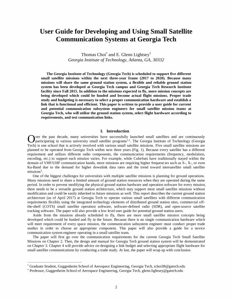
planned to be operated from Georgia Tech within next three years (Fig. 1). Because every satellite has a different
requirement and utilizes different radio components, the communication requirements (frequency, modulation,
encoding, etc.) to support each mission varies. For example, while CubeSats have traditionally stayed within the
domain of VHF/UHF communication bands, more missions are requiring higher frequencies such as S-, X-, or even
Ka-Band due to the demand for higher downlink data rates and the trend toward intersatellite small satellite
missions3.
One of the biggest challenges for universities with multiple satellite missions is planning for ground operations.
Many missions need to share a limited amount of ground station resources when they are operated during the same
period. In order to prevent modifying the physical ground station hardware and operation software for every mission,
there needs to be a versatile ground station architecture, which may support most small satellite missions without
modification and could be easily inherited to future missions as well. This report describes the current ground station
architecture (as of April 2017) at Georgia Tech to operate various small satellites with different communication
requirements flexibly using the integrated technology elements of distributed ground station sites, commercial off-
the-shelf (COTS) small satellite operation software, software-defined radio (SDR), and open-source satellite
tracking software. The paper will also provide a low level user guide for potential ground station users.
Aside from the missions already scheduled to fly, there are more small satellite mission concepts being
developed which could be funded and fly in the future. Because there is no single communication hardware which
will meet requirement of every space mission, the communication subsystem engineer must conduct proper trade
studies in order to choose an appropriate component. This paper will also provide a guide for a novice
communication system engineer operating in a small satellite team.
The paper will first go over the communication requirements for the current Georgia Tech Small Satellite
Missions on Chapter 2. Then, the design and manual for Georgia Tech ground station system will be demonstrated
on Chapter 3. Chapter 4 will provide advice on designing a link budget and selecting appropriate flight hardware for
small satellite communications by conducting a trade study. At last, the paper will wrap up with conclusion.
* Graduate Student, Guggenheim School of Aerospace Engineering, Georgia Tech, [email protected] † Professor, Guggenheim School of Aerospace Engineering, Georgia Tech, [email protected]
O
3
Figure 1: List of Georgia Tech Small Satellite Missions
II. Communication Requirements for 2017-2018 Georgia Tech Small Satellite Missions
As mentioned in the introduction, Georgia Tech is scheduled to fly five small satellites within next three years
(Fig. 1). Considering the fact that the small satellites placed into Low Earth Orbit (LEO) are usually expected to last
from six to twelve months, there will be time overlaps between periods of time when the different missions operate.
While the communication hardware each satellite mission flies will be different, they will communicate through a
single ground station system at Georgia Tech. Therefore, the Georgia Tech ground station needs to be able to
process various types of communication signals. In this section, the various small satellite missions operated by
Georgia Tech are briefly reviewed (Table 1), mainly to understand the requirement of the Georgia Tech ground
station.
A. RANGE
RANGE (The Ranging And Nanosatellite Guidance Experiment) is the first mission which will be operated by
the Georgia Tech ground station. The mission was selected by a Terra Bella University Cubesat Partnership for
launch in Fall 20174. Two 1.5U CubeSats will be deployed to study positioning capabilities. Absolute positions of
the RANGE satellites will be validated using GPS receivers and ground-based laser ranging measurements and
relative positions will be validated through intersatellite optical ranging between each other. The intersatellite optical
ranging will also double as low-rate optical communication link. For radio frequency communication, both RANGE
satellites use the NanoCom ANT430 omnidirectional canted turnstile UHF antenna system and the NanoCom
AX100 half-duplex UHF transceiver from GomSpace, with Gaussian Frequency Shift Keying (GFSK) modulation
and AX.25 data link layer protocol. The data rate will be 9.6 kilobits per second (kbps). Because RANGE is a two-
satellite mission, communication requirements for RANGE include simultaneous contact with two satellites during
each ground station overflight.

4
Table 1: Georgia Tech Small Satellite Missions Overview
Mission Features Program Size Frequency Band
(Uplink/Downlink)
Launch
Year
RANGE
Laser ranging, optical
intersatellite
communication
Terra Bella
University CubeSat
Partnership
Two 1.5U UHF/UHF 2017
Prox-1
Automated trajectory
control and inspection of a
deployed CubeSat
Air Force UNP – 7 22’’x 24’’
x 12’’ UHF/S-band 2018
ARMADILLO
(U. Texas)
Dust and debris
characterization and
radio-occulation
Air Force UNP – 7 3U VHF/UHF 2018
RECONSO Detect and track small
space objects Air Force UNP – 8 6U UHF/UHF 2019
MicroNimbus Radiometer observing
atmosphere GTRI 3U UHF/S-band 2019
USIP Inflatable LiDAR target
imaging NASA USIP 3U UHF/UHF 2019
B. Prox-1
Prox-1 is a nanosatellite with size of 56 by 61 by 30.5 cm (66.5 kg) selected by University Nanosatellite Program
(UNP) - 7 from Air Force Research Laboratory (AFRL) 5. It is planned to be be launched on the SpaceX Falcon
Heavy rocket in winter 2017 or early 2018. The main objectives of Prox-1 are to deploy a 3U CubeSat solar sail
(Lightsail) built by The Planetary Society and demonstrate automated trajectory control based upon relative orbit
determination using infrared imaging technology. It will also downlink photos of the solar sail deployment. The
frequency requirement for Prox-1 includes UHF frequency uplink and S-band frequency downlink. Hardware
includes a RX-445 UHF receiver and TX-2400 S-band transmitter from SpaceQuest Ltd., along with a KPC-9612
terminal node controller from Kantronics to apply Frequency Shift Keying (FSK) modulation and AX.25 protocol
on signals. Prox-1 will utilize an S-band ground station located fifteen miles away from campus for downlink and
UHF station on campus for uplink.
C. ARMADILLO
ARMADILLO (Attitude Related Maneuvers and Debris Instrument in Low Orbit) is a 3U CubeSat built by
University of Texas at Austin (UT-Austin), in collaboration with Baylor University and University of Stuttgart6.
Like Prox-1, it was selected for flight by UNP – 7 from AFRL and will launch as a secondary payload on the same
SpaceX Falcon Heavy rocket in winter 2017 or early 2018. While it is a mission from UT-Austin, it is planned to be
operated by the Georgia Tech ground station. ARMADILLO will characterize in-situ sub-millimeter level dust and
debris particles in LEO using a Piezo Dust Detector developed by Baylor University and demonstrate ionospheric
radio-occultation with a FOTON GPS receiver developed UT-Austin. ARMADILLO communicates with the ground
station through the deployable antenna from ISIS and the Helium 100 UHF downlink/VHF uplink radio developed
by Astronautical Development LLC (Astrodev), with GFSK modulation and AX.25 data layer link protocol.
D. RECONSO
RECONSO (RECONnaissance of Space Objects) is a 6U CubeSat selected for flight by UNP-8 from AFRL7. It
is planned to launch as a secondary payload in 2018. The goal of RECONSO is to demonstrate space surveillance
capabilities by detecting and tracking resident space objects in the 1-10 cm regime using a visible lens and CMOS
imager. RECONSO will both uplink and downlink at UHF with FSK modulation, using a PI-1310 UHF radio from
Tyvak Inc.
5
E. MicroNimbus
MicroNimbus is a 3U CubeSat project from Georgia Tech Research Institute. MicroNimbus is a collaboration
between GTRI, Georgia Tech Aerospace Engineering Department (for satellite bus), and Georgia Tech Electrical
Engineering Department (for radiometer). It will observe the atmosphere from LEO. It has two separate
communication systems, one for high data rate and another for low data rate. High data rate system uses S-band
frequency and QPSK modulation to downlink mission data and low data rate uses UHF frequency and GMSK
modulation to uplink command data and downlink telemetry data. The two radio hardware used are STX-C from
Clyde Space and AX100 from GomSpace.
F. TARGIT
Georgia Tech has been selected by NASA USIP (Undergraduate Student Instrument Project) to develop an
imaging LiDAR CubeSat mission for planetary applications known as TARGIT. This satellite is planned to launch
in 2019 or 2020. TARGIT will deploy a LiDAR target, which will unfold and inflate after detaching from the top of
the CubeSat. The CubeSat will then acquire images of the target through LiDAR until the target is out of range. This
mission will use the NanoCom AX100 half-duplex UHF transceiver from GomSpace. Antenna, modulation, and
protocol have not been determined yet.
III. Georgia Tech Ground Station Architecture Overview
A. Three Stations, One System
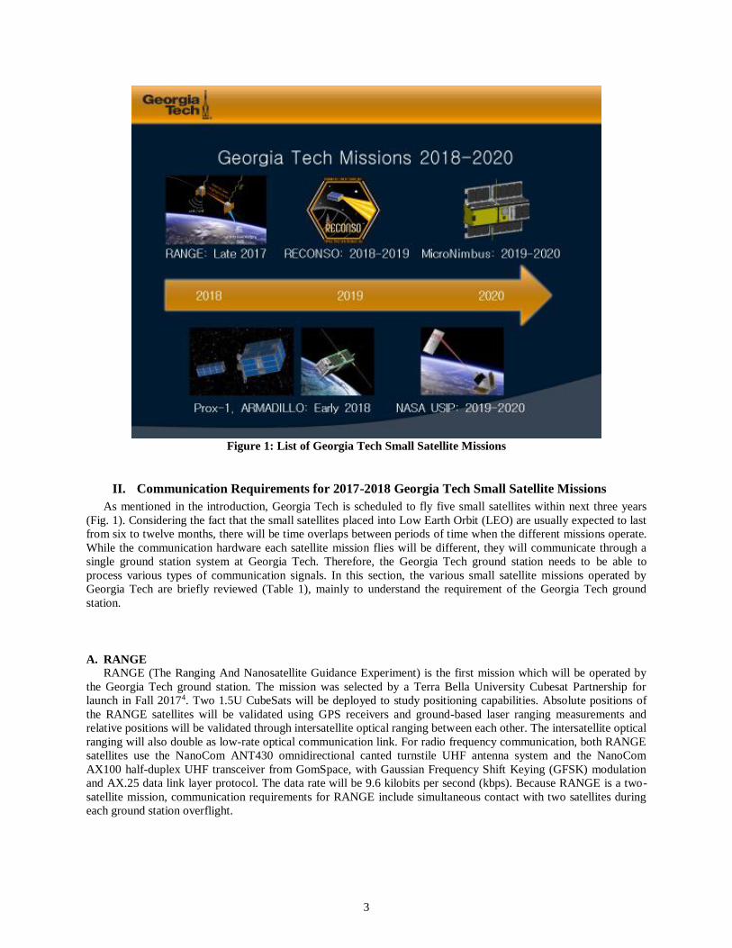
Frequency requirement is the most limiting factor in designing a ground station because most RF equipments are
tailored for narrow range of frequencies. Therefore, Georgia Tech ground station will use a network of three
different stations: the S-band station at the Georgia Tech Research Insitute’s Cobb County Research Facility (CCRF
station), the VHF/UHF station on the Van Leer building at the Georgia Tech main campus (VL station), and the
UHF station on the Montgomery Knight building at the Georgia Tech main campus (MK station). A central server
located in the Engineering Science and Mechanics (ESM) building, also located at the Georgia Tech main campus,
controls all three of these stations. These stations can operate independently or in concert. For example, the Prox-1
mission will require an uplink in UHF from MK station, but will downlink in S-band to the CCRF station. The
RANGE mission is another example. The RANGE mission is composed of two satellites, which initially will be
close together and will be drifting apart as time passes due to lack of propulsion system. Thus, a single ground
station (either MK or VL) with 21 degrees antenna beamwidth will be used to track both satellites at first, but two
stations (the MK station and the VL station) will be used simultaneously for communication with drifted satellites.
Fig. 2 shows the three ground stations and their approximate locations in the Atlanta area.
Figure 2: Locations of Georgia Tech ground stations throughout Atlanta

6
B. Flow of Uplink/Downlink Data
While each station operates in different frequency bands using different RF hardware, they share a common
architecture. Every station has an RF front end connected to a software-defined radio (SDR) for uplink and
downlink. SDR’s characteristics and benefits will be explained later. Each station is controlled by a server computer,
which controls antenna pointing, monitors station health data, and runs the digital signal processing software to
drive the SDR. Because each station uses different hardware, the drivers for these operations are different, but each
server has a common external interface, so the central system will interact with each station in the same way. Fig. 3
shows a block diagram of the interaction between the central system and a single remote facility (CCRF, MK, or
VL). The overall network between the central system and remote facilities is supported by IT services at Georgia
Tech Aerospace Engineering department (GTAE-IT).
Figure 3: This block diagram explains the data flow within the ground station system. The purple arrow is
the flow of command data to control antenna rotors, the red arrow is the flow of uplink data to satellite, and
the cyan arrow is the flow of downlink data to operator. All three remote stations have the same connection
interface, while using different rotors and different RF front ends.
For the downlink process, data from a satellite comes down the RF chain where the signal is amplified before
entering the SDR where the signal is processed and changed to digital data to the server at a single remote facility.
Then, the server will route the data received to central system’s “Clearinghouse” at the ESM building.
Clearinghouse is a central server which acts as a router to selected ground station when uplinking, and a storage of
satellite data when downlinking. At last, the downlink data will be sent over to QuantumCMD to visualize the data
for the satellite operation team.
QuantumCMD is a mission operation software package, which will be explained in a later section. The main
reason we need Clearinghouse as a router between the central system and the remote facility is that QuantumCMD
may only interface with a single ground station. In total, three full copies of all uplink and downlink messages with
timestamps will be archived, one in QuantumCMD, one in the clearinghouse, and one in the remote station’s server.
This gives several different backups to prevent data loss, and to trace problems that may arise in data handling chain.
For uplink, QuantumCMD will generate the commands, which will be routed at Clearinghouse to a chosen
ground station. This data at remote station then will be encoded and modulated at SDR, which will be sent out as a
RF signal through the chain of RF equipment.
For status of the overall system, the networking between servers has been approved by the GTAE-IT, and all the
hardware components have been bought and installed. The clearinghouse’s routing software is yet to exist.
Figure 4: RF filter (DCI-145-435-DX-DB)'s S21 measured by a network analyzer at UHF frequency band. It
is important to test the RF equipment before installing them.

7
C. RF Hardware
Selecting appropriate frequency bands for communication is crucial when purchasing RF hardware for ground
station. First, Federal Communications Commission (FCC) must approve the frequency selected. The
communication engineer may check this through FCC frequency allocation chart and applying for a frequency.
In addition, the chain of RF hardware must all be functional at a selected frequency. Some of the components
might be functional over a wide range of frequencies (for example, an amplifier that is functional over 400 to 480
MHz), but if another component is only functional over a narrow range of frequencies (for example, a filter that is
functional over 430 to 440 MHz), then the narrower range of frequencies should be used. Otherwise, the signal
power will be reflected back and damage the hardware, causing ground station breakdown. Because RF equipment
for ground station is expensive and the backup hardware is limited, it is highly recommended to test the S-
parameters using network analyzer at Van Leer Electrical Engineering building before actually installing the
components (Fig. 4).
This section will go over each of the stations at Georgia Tech to explain current configurations and properties.
i) Cobb County Research Facility S-band Station
The CCRF station has an S-band (2200-2310 MHz) antenna system, manufactured by Orbital Systems Ltd. The
system includes a 3m dish antenna, a high performance low noise amplifier (LNA) for the receiver (with G/T value
of 13.5 dB/K), a high power amplifier (HPA) for 50W transmit power, positioning rotors capable of driving the
antenna at 60 degrees per second in azimuth and elevation, and a control computer for tracking the satellite with
TLE data and monitoring the health of the ground station system. The station has a beamwidth less than 3 degrees,
pointing loss less than 0.1 degrees, and circular polarization. The server at CCRF can be remotely accessed through
GTAE network. The S-band ground station system is shown and explained in Fig. 5.
Status of the S-band station is that it is fully functional and ready to be used. It can sense RF signal and track
moving satellites. The author would recommend trying to receive actual data from S-band satellites.
Figure 5: S-band station at CCRF. First photo shows a 3m dish antenna system covered by a radome. Second
photo shows the workstation next to the antenna system, with SDR and antenna controller connected to the
server, through USB 3.0 connector and Ethernet cable respectively. SDR is connected to a RF cable, which
goes to the RF hardware system within the radome.
Figure 6: Flow of RF signals between the SDR and the antenna at the VL/MK stations. Red arrow indicates
the uplink path and the cyan arrow indicates the downlink path.

8
ii) Van Leer VHF/UHF Station
The Van Leer station is a VHF/UHF station built using amateur radio equipment. The station is actually owned
by the Georgia Tech Amateur Radio Club (W4AQL), but will collaborate with the Aerospace department to support
spacecraft missions. The VL station is a VHF/UHF station, built using amateur radio equipment. It is currently
configured to uplink in the VHF (144-148 MHz) band and downlinks in the UHF (430-440 MHz) band. The uplink
uses two different amplifier stages, one to bring the less than 10 mW SDR output to 1 W, and another to bring that
signal up to 50 W (Fig. 6). A two-stage architecture was chosen because of the very large amount of amplification
required; it was more cost-effective to use two amplifiers rather than a much larger amplifier. Both the VHF and
UHF antennas are circular polarized Yagis from M2 vendor (2MCP22 and 436cP42UG). For downlink, the received
signals are sent to a band pass filter then to a LNA mounted on the antenna mast before heading to the SDR. The VL
station uses an SP-70 LNA with a 0.7 dB noise figure, and G/T is expected to be -13 to -14 dB/K.
Current status of the Van Leer station is that it is fully functional and can track satellites, but the bandpass filter
from DCI has not been installed yet.
iii) MK VHF/UHF Station
The MK station uses the same receiver components as the VL station, but it transmits at UHF (430-438 MHz)
frequency band. The MK station’s UHF uplink is a similar two-stage amplifier setup as the VL station, but with 30
W output power instead of 50 W. The dual UHF Yagi antennas at the MK station will be combined as a phased
array to increase the antenna gain; both used for receive and transmit with an RF switch. A spare VHF antenna and a
dish antenna are attached for backup/future use if necessary. Fig. 4 describes the flow of RF signals between the
SDR and the antenna for the VL and MK stations.
The MK station needs several hardware work to be done. First, a second stage UHF amp from TE systems have
a problem because when uplink occurs, much power is reflected back to the receiving end of the SDR, which may
break the SDR. The amp is modified to include a RF relay to dump powers to 50-ohm load when transmitting, but it
has not been tested. In addition, the bandpass filter is not installed yet, while the waterproof box is made and ready
to go. Lastly, the RF splitter needs to be installed to use two antennas as a phased array instead of one.
Figure 7: QuantumCMD web interface
9
D. QuantumCMD/Networking between Servers
To control this network, Georgia Tech is using the QuantumCMD software, developed by Kratos Defense &
Security Solutions, Inc. for spacecraft command and control. Using COTS software for mission operations reduces
the risk of writing different operation software for fast turnout small satellite missions and provides a common user
to machine interface for different types of missions. It also has a user-friendly web based visual interface (Figure 7),
automation features, and easy access over the internet. QuantumCMD is capable of parsing incoming messages and
generating responses using user-created mission scripts. QuantumCMD can store a large number of such scripts,
which will be developed for each mission by the mission specific operations team. Uplink commands are sent from
QuantumCMD to the central server (clearinghouse), which routes the messages to the appropriate ground station for
transmission, along with pointing commands for the rotor and signal power level settings. Downlinked telemetry is
automatically scanned for any variables that may indicate off-nominal performance, such as low battery voltage or
high current draw. These red flags can trigger automatic notifications to the relevant operations team. The telemetry
is also provided to QuantumCMD’s web interface for customizable visualization.
Status of QuantumCMD is that the accounts can be set to provide access privileges and QuantumCMD server
can now send messages and receive messages from different servers within GTAE network.
To add a new user, go to “Control Panel” from admin’s account. On left side, there is “Users and Organizations”
tab under “Portal”. Press “Add” and add a new member with the member’s name and email address, and press roles
on the right to provide a privilege the new member should receive. Then, go to “User Groups” tab under “Portal”.
On the right of “quantumCMD_User”, there is “Actions” button. Press it, and press “Assign Members”. Then, check
the members you would like to add from “Available” tab, and press “Update Associations”. More information can
be found from guides on mackerel>Common>Operations or by contacting Kratos Defense Technology’s Justin Boss
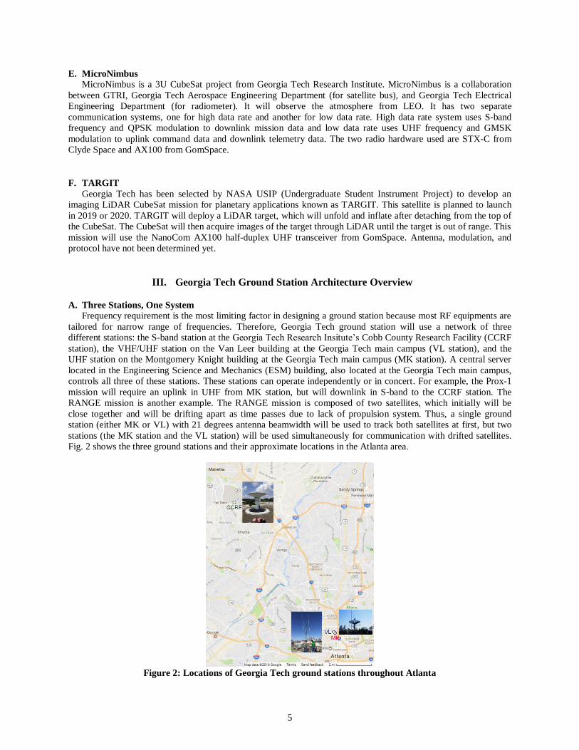
In order to enable communications, Firewall setting has to be configured first. To allow QuantumCMD to
receive messages from an arbitrary server, follow page 11&12 of QuantumCMD Core User Guide on mackerel
server, and open a port with an arbitrary number and desired connection type (TCP/UDP). To send a message from
QuantumCMD to a chosen server, see Fig. 8.
Figure 8: Opening a port to receive information from QuantumCMD/different server. (ufw status) shows
what ports are currently opened, and (ufw allow from <ip-address> proto <protocol> to any port <arbitrary
number>) opens a new port.
After the ports open, QuantumCMD can send a message to a server by going to “Utilities>Connection
Diagnostics” page from the main page of web interface. Then, write commands on command lines to set host

10
number, port number and protocol (see pg. 125 from the Core User Guide). Lastly, right click the command line,
select “Command Formatter”, and send a command from the list. If the server has been listening on the selected ip
address and port number using an rx python script, the message would show. To send a message from a server to
QuantumCMD, use a tx python script, and the received bits will show on the “Frame Bits” on “Connection
Diagnostics” page. “UDP Communications” page on python wiki contains a sample rx and tx files.
While the networking of the QuantumCMD has been set, the formatting of the xml files and interfacing with
ground systems using GEM protocol must be studied to format the system for a specific satellite and a rotor.
E. Digital Signal Processing
The digital signal processing is performed using GNU Radio (Fig. 9), an open source project to provide support
for the use of SDRs. It provides libraries for basic DSP functions, like signal filtering and common modulation
schemes. These libraries are user-extensible, and many custom functions are used in the GT ground station. GNU
Radio also provides a flow control manager to regulate the program in real time, and a graphical interface similar to
LabView for prototyping. The GT ground station software is capable of using CCSDS and AX.25 packet protocols,
and can perform GFSK and Quadrature Phase Shift Keying (QPSK) modulation/demodulation. Once the signals are
modulated, the baseband signal is sent to the SDR, where it is upconverted to the correct frequency and transmitted.
The SDR used in all three stations is the Ettus Universal Software Radio Peripheral (USRP) B210. The B210 is a
very capable radio, with two input and two output channels, 56 MHz of real-time bandwidth, and RF coverage
tunable from 70 MHz to 6 GHz.
One of the many advantages of using an SDR is that it may produce various waveforms based on the mission’s
needs. For example, to communicate with two satellites in close proximity, the antenna is aimed at the midpoint, and
the radio can create two simultaneous uplink messages by adding the baseband waveforms of each individual
message, provided the uplink frequencies are within 56 MHz of each other. It is also capable, through the GNU
Radio, of employing any modulation and encoding scheme. This flexibility is very important when supporting many
different missions, each with a different spacecraft radio.
Currently, GFSK signal can be uplinked and downlinked, but the interface with the clearinghouse and signals
utilizing other modulations need to be developed.
Figure 9: An example of a GNU Radio flow graph processing downlink signal with GFSK modulation and
AX.25 framing. The signal is filtered using a low pass filter and a power squelch to only process signals near
center frequency and strong enough power. The necessary signal processing blocks are added to demodulate
and deframe the signal to get the binary data at the end of the chain.
F. Tracking
For tracking software, the Gpredict open-source software8 is used to monitor and track multiple satellites in real
time at the MK and VL stations (Fig. 10). Gpredict contains a satellite database with known Two Line Elements
(TLE). It may update TLE information, group chosen satellites into modules, and control antenna rotor from

11
different vendors. It also provides a user-friendly visual interface, where an operator may position ground station
antennas and observe satellites nearby.
In the CCRF station, the antenna system is preinstalled with its own tracking software.
Figure 10: Gpredict Screenshot
IV. Communication Subsystem for Small Satellites Missions
A. Choosing a Flight Radio/Antenna
The purpose of the flight communication hardware is to reliably transmit telemetry data and mission data back to
the ground station and receive commands from the ground station. Communication engineer has to consider
following factors when choosing a flight hardware.
The flight hardware should first meet the mission requirement. What is the purpose of the mission? A mission
may test communication capability of a newly built radio/antenna or may just require very reliable spacecraft
communication system with high technology readiness level (TRL) among COTS components. Is this a LEO
satellite mission or deep space satellite mission? Directional antenna must be used for deep space missions as the
signal power decreases with increased link distance. Higher frequency may reduce the size of the antenna without
loss of gain, but higher frequency suffers from severe atmospheric loss or rain loss.
Various budgets must be considered when selecting communication hardware. What is the data budget and how
much data rate is required? Because more data rate can be transmitted with wider bandwidth (Shannon limit: C =
B*log2(1+S/N), with C being the channel capacity in bps, B being the bandwidth in Hz, and S/N being signal to
noise ratio), higher data rate would be more easily achieved if higher center frequency is used. In addition, there are
many other budget questions including: How much money can be used on communication subsystem? How much
space within satellite is allowed for communication subsystem? How much power can a transmitter use? In order to
narrow down the communication hardware, these questions need to be answered by discussing with system engineer,
mechanical engineer, and power engineer accordingly.
Lastly, the flight hardware should be compatible with the communication system on the ground station. Even if
the flight communication system is working without problem, if the ground station does not have meet the
requirements (frequency, modulation, coding, protocols, etc.) to talk to the spacecraft, communication will fail.
Communicating with the ground station engineer is essential, not only to know about the capabilities and limitations
of the ground station, but also to schedule communication tests and satellite operations. Georgia Tech ground
station’s properties are described in the section III.
12
B. Hardware Market
“Small Spacecraft Technology State of the Art9” provides a list of small spacecraft hardware available with TRL
higher than 7 (7: system prototype demonstration in a space environement). According to this report, the most
notable vendors for small spacecraft communication hardware at VHF/UHF frequencies include Astronautical
Development LLC, BitBeam Inc., Cylde Space Ltd., GOMSpace ApS, Haigh-Farr Inc., ISIS, and L3
communications Inc. The manufacturers for S-band frequency hardware include Astronautical Development LLC,
Cylde Space Ltd., Haigh-Farr Inc., Innoflight Inc., IQ Wireless GmbH, ISIS B.V., and Vulcan Wirelsss Inc. The
report contains information about less common bands as well, including L-band, X-band, Ku- to Ka- band, optical
frequency. Because the lower frequencies are very crowded, more small satellite missions are moving toward higher
frequencies, such as X-band and Ka-band.
C. Link Budget Calculation
The easiest way to calculate link budget for a small satellite mission is to use Amateur Satellite/The International
Amateur Radio Union (AMSAT/IARU) Annotated Link Model System spreadsheet calculator10. This spreadsheet
was first developed in 2005, and was updated constantly, with most current version being version 2.5.5 in 2016.
Communication system engineer using the spreadsheet has to go through each of the tabs (i.e. Orbit, Frequency,
Transmitters, Receivers, Gains, Losses, etc.), and follow instructions to fill in the cells, according to the information
from mission requirements documents, flight hardware spec sheets and ground station hardware spec sheets. Some
of the information, such as atmospheric loss and rain loss, might require further research from external literature11.
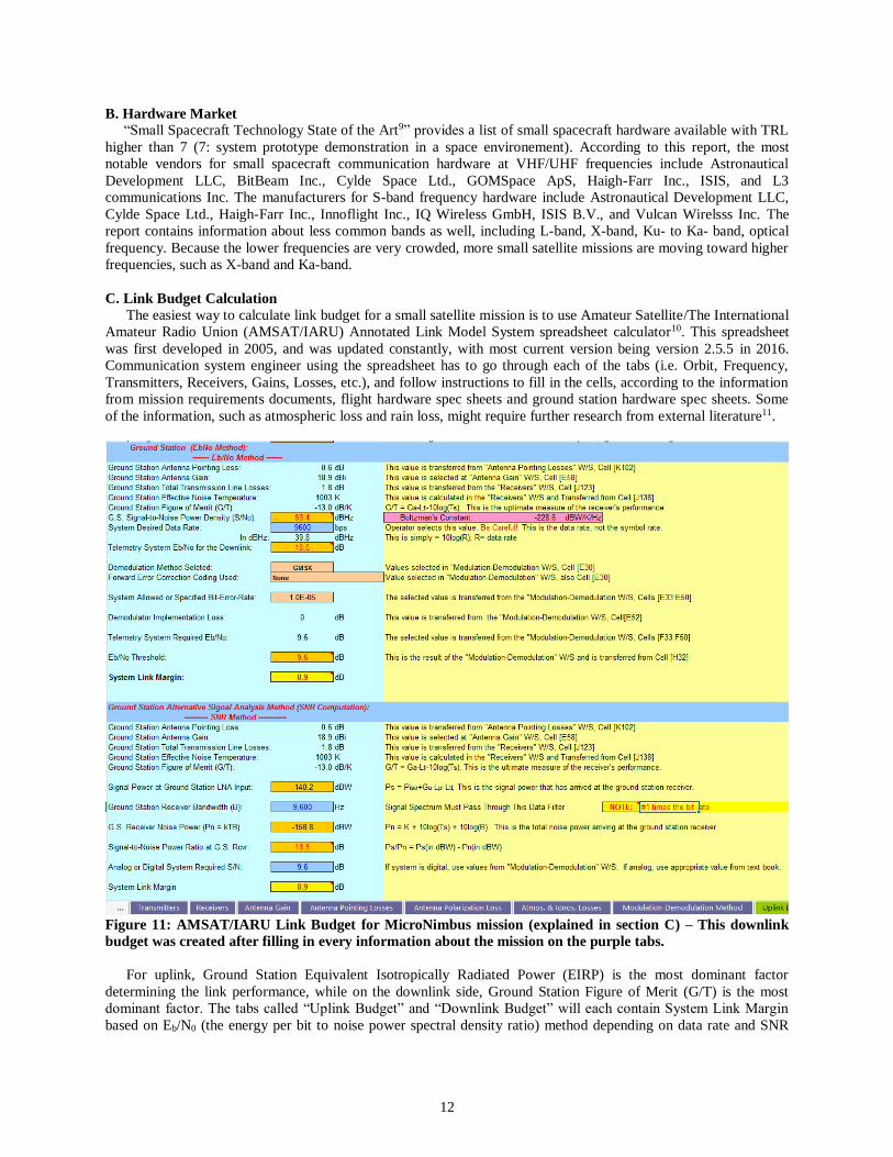
Figure 11: AMSAT/IARU Link Budget for MicroNimbus mission (explained in section C) – This downlink
budget was created after filling in every information about the mission on the purple tabs.
For uplink, Ground Station Equivalent Isotropically Radiated Power (EIRP) is the most dominant factor
determining the link performance, while on the downlink side, Ground Station Figure of Merit (G/T) is the most
dominant factor. The tabs called “Uplink Budget” and “Downlink Budget” will each contain System Link Margin
based on Eb/N0 (the energy per bit to noise power spectral density ratio) method depending on data rate and SNR
13
(signal to noise ratio) method depending on receiver bandwidth (Fig. 11). The margin decreases if the data rate or
bandwidth increases.
One thing to note is that when the author was working on S-band downlink budget for MicroNimbus mission,
filling in every cell on “Receivers” tab was difficult because the Cobb County S-band station is a system bought in
full from Orbital Systems, unlike VHF/UHF stations on Georgia Tech built from individual components purchased
from amateur radio vendor. However, since the actual G/T was measured to be 13.5 dB/K when the S-band station
was installed and tested in summer, 2016, adjusting noise and gain values on “Receivers” and “Antenna Gain” tabs
to set G/T value to 13.5 dB/K on “Downlink Budget” tab was sufficient.
The rule of thumb in the aerospace industry is, the link between a satellite and a ground station closes if the
margin is above 3 dB (final Eb/N0 or SNR is twice the minimum Eb/N0 or SNR allowed to close link). However, the
AMSAT/IARU link model assumes 6 dB to be a bar for a “sufficient” link margin. Author recommends readers to
be conservative when building a link budget. For example, the elevation on orbits tab should be low (5 to 10
degrees) and system noise temperature on receivers tab should be high (especially in the noisy city environment). A
datasheet provided from AX100 flight hardware contained a sample link budget for UHF communication, which
was a good reference budget to compare to12.
C. Case Study: Communication Subsystem Development for MicroNimbus Mission
The purpose of this section is to explain about the duties of communication subsystem engineer at a small
satellite team.
The author worked as a communication subsystem engineer for MicroNimbus mission at Georgia Tech.
MicroNimbus mission is a collaboration between GTRI and Georgia Tech, to conduct meteorological research using
a radiometer payload. MicroNimbus’s bus structure is modeled after a TECHBUS13, developed by a former student
at Georgia Tech. TECHBUS contains two communication systems, with UHF band frequency for low data rate
communication (command/telemetry), and S-band frequency for high data rate communication (mission data). The
radio components selected for TECHBUS were GOMSpace’s AX100 UHF radio and Clyde Space’s STXc S-band
radio. The S-band frequency will only be used for downlink because uplink data rate can be low. The antennas
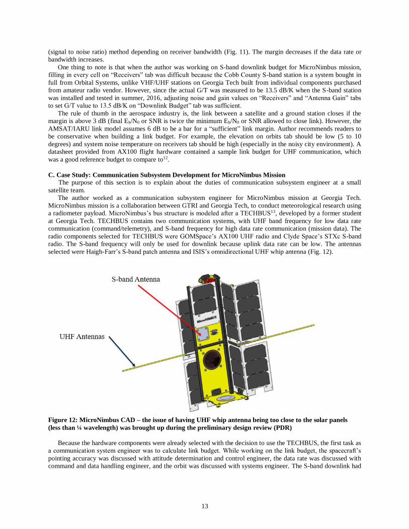
selected were Haigh-Farr’s S-band patch antenna and ISIS’s omnidirectional UHF whip antenna (Fig. 12).
Figure 12: MicroNimbus CAD – the issue of having UHF whip antenna being too close to the solar panels
(less than ¼ wavelength) was brought up during the preliminary design review (PDR)
Because the hardware components were already selected with the decision to use the TECHBUS, the first task as
a communication system engineer was to calculate link budget. While working on the link budget, the spacecraft’s
pointing accuracy was discussed with attitude determination and control engineer, the data rate was discussed with
command and data handling engineer, and the orbit was discussed with systems engineer. The S-band downlink had

14
a margin of 5.3 dB at 2 Mbps data rate, the UHF downlink had a margin of 8.9 dB at 9.6 kbps data rate, and the
UHF uplink had a margin of 25.9 dB at 9.6 kbps data rate.
The second task was testing the S-band radio and the antenna to see if they were functional (other students took
charge of the UHF components). Using beaglebone and a built in I2C driver on python, the radio could turn on its
power amplifier and send RF signals to SDR. Other features of the radio were also tested, included frequency
change, power change, and mode change.
The S-band antenna was then taken to the antenna lab at Van Leer building to be tested. The S-parameter was
measured using a network analyzer and the gain pattern was measured using a signal generator and an antenna probe
(Fig. 13). This technique was taught through ECE 4370 Antenna Engineering course and the corresponding lab
course (Professor Greg Durgin). The S11 showed that the antenna was functional between 2.2 to 2.22 GHz. The gain
pattern, however, was messy than expected. This is due to measuring gain pattern in a noisy environment. In order to
achieve an accurate result, the measurement must be made at an anechoic chamber.
Figure 13: S-parameter measurement and the gain pattern measurement results
The third task was writing a C++ device driver for the S-band radio. Functions of the drivers included setting
modes, setting data rate, setting power level, setting frequency, turning on power amp, turning off power amp,
resetting, and getting the status of the hardware. Communicating with software engineer when writing a driver is
important, as the software engineer may want a driver in specific format.
Lastly, the gain pattern modification due to CubeSat’s metal structure was been studied by the EM simulation
using High Frequency Structural Simulator (HFSS) from ANSYS. During the preliminary design review, one of the
payload antenna engineer was worried about the UHF antenna located too close to the solar panel, as a metallic
structure located closer than ¼ wavelength may cause the gain pattern to alter. Because the downlink margin was 8.9
dB, if the gain was altered by more than 5 dB, there could be communication failures. HFSS is available on ECE
computers at Georgia Tech for free. The guide for HFSS could be found on Youtube.
Figure 14: 2D view of the gain pattern for CubeSat without PEC panels and with PEC panels – The gain
pattern changes a lot just by having two PEC panels

15
Two cases were compared: dipole antenna with CubeSat body but no panels and dipole antenna with CubeSat
body and panels on the side (Fig. 14). The dipole antenna used in the simulation is not the actual UHF dipole
antenna from ISIS, but a custom designed antenna by the author to be resonant near 440 MHz (Fig. 15). Each panel
was assumed to be 10 by 30 by 10 mm PEC (perfect electric conductor), which would simply provide the worst case
scenario for the gain pattern due to its conductivity. The CubeSat body was also assumed to be PEC.
Figure 15: S11 of the dipole antenna – it is resonant at about 445 MHz
The results showed that the close to omni-directional gain pattern (2.7 dB omni) changed to a very directional
gain pattern. The change of gain pattern occurs from reflections causing the waves to be added constructively and
destructively. The gain is also directional toward behind the panel (7.6 dB downward in Fig. 14) instead of toward in
front of the dipole antenna (-5 dB upward in Fig. 14), where the satellite is facing the ground station. For this worst
case scenario, there is more than 7.7 dB loss for the main direction where the satellite is pointing, which may cause a
downlink failure.
Another information worth mentioning is that the hole within the CubeSat body where the antenna comes out
needs to be large enough. If the hole was too tight and the space between the antenna and the metallic CubeSat body
was too close, the gain pattern also changed from omni-directional pattern as the metallic body acted as part of the
antenna.
This is only the worst case with low accuracy to the actual model that was simulated due to lack of time and
information. If the actual solar cells are added and material properties change from PEC, the gain pattern could be
degraded less. Yet, author recommends the MicroNimbus team to actively look into modifying the mechanical
design to locate the antenna away from the panel in case there is no time for EM analysis. Otherwise, the antenna
will need to be accurately modeled, simulated, and tested.
V. Conclusion Georgia Tech’s satellite ground station network is composed of three individual ground stations to support the
varying communication requirements of small satellite missions from Georgia Tech and other academic institutions.
The ground station is planned to debut when the RANGE satellites are launched in fall of 2017. Overall structure of
the Georgia Tech ground station is flexible enough to support various mission requirements with the use of easily
customizable operations software, software defined radios, and user friendly open source tracking software.
Becoming a communication systems engineer for a small satellite team means conducting various trade studies
to find appropriate radio and antenna for satellite, creating an accurate link budget, testing the communication
hardware, and considering every little detail which may hinder or help the communications. Overall, this paper is
written to serve as a user guide for ground station users and novice communication system engineers.
16
VI. Acknowledgments
This paper is written for AE 8700: Special Problems course, to meet the graduation requirement for Master of
Science degree at Georgia Tech Aerospace Engineering Department. All the work was done between August 2015
and April 2017 at Space Systems Design Lab-Lightsey Research Group (SSDL-LRG), under Professor E. Glenn
Lightsey’s guidance. The author acknowledges Professor Glenn Lightsey for advising and providing research funds,
Georgia Tech Ground Station Working Group (GSWG) for sharing communication requirements, Amateur Radio
Club W4AQL for providing a backup station, Michelle Hall for purchasing a large number of equipment, Diego
Remolina for IT support, and many students from SSDL for helping to build the ground station, especially Terry
Stevenson, Sterling Peet, and Patrick Tarrant.
VII. References
1 Hunyadi, G., Ganley, J., Peffer, A., and Kumashiro, M, “The University Nanosat Program: an adaptable, responsive and
realistic capability demonstration vehicle,” Aerospace Conference, 2004, Proceedings. 2004 IEEE, Vol. 5, 6-13 Mar. 2004, pp.
2858. 2 Allmen, J. and Petro, A., “Small Spacecraft Technology Program (SSTP) – Projects 2014 - 2015,” NASA FS #2014-07-02-
ARC. 3 Cheung, K-M., “Ground Network Architecture for Interplanetary Smallsat Missions,” 14th Annual CubeSat Developers
Workshop, Cal Poly State University, San Luis Obispo, CA, 2015. 4 Gunter, B., Davis, B., Lightsey, E. G., and Braun, R., “The Ranging and Nonosatellite Guidance Experiment (RANGE),”
Proceedings of the AIAA/USU Confernence on Small Satellites, Guidance and Control, SSC16-V-3., Logan, UT, August 2015.
http://digitalcommons.usu.edu/smallsat/2016/S5GuidCont/3/. 5 Okseniuk, K., Chait, S., Schulte, P., and Spencer, D., “Prox-1: Automated Proximity Operations on an ESPA Class
Platform,” Proceedings of the AIAA/ USU Confernence on Small Satellites, Education, SSC15-IX-4, Logan, UT, August 2015. http://digitalcommons.usu.edu/smallsat/2015/all2015/63/.
6 Laufer, R., Lightsey, G., Herdrich, G., Srama, R., Earle, G., Wiedemann, C., Chester, E., Hill, H., Henderson, T., Sandau,
R., Matthews, L., and Hyde, T., “ARMADILLO – A Demonstration for Low-Cost In-Situ Investigations of the Upper
Atmosphere of Planetary Bodies,” Proceedings of International Planetary Probe Workshop (IPPW), Science from Probes and Penetrators, IPPW-8-3, Portsmouth, VA, June 2011, http://solarsystem.nasa.gov/docs/a145.pdf.
7 Coder, R., “Multi-Objective Design of Small Telescopes and Their Application to Space Object Characterization,” Ph.D.
Dissertation, Guggenheim School of Aerospace Engineering, Georgia Tech, Atlanta, GA, 2016. 8 Csete, A., “Gpredict User Manual: Updated for Gpredict 1.3,”Alexandru Cste and Contributers, 2011.
https://sourceforge.net/projects/gpredict/files/Gpredict/1.3/
9 Shimmin, R., “Small Spacecraft Technology State of the Art,” Mission Design Division, Ames Research Center, Moffett
Field, California, 2015.
https://www.nasa.gov/sites/default/files/atoms/files/small_spacecraft_technology_state_of_the_art_2015_tagged.pdf 10 King, J. “AMSAT/IARU Annotated Link Model System,” AMSAT/IARU, 2016.
http://www.amsatuk.me.uk/iaru/spreadsheet.htm
11 Ippolto, L., “Radiowave Propagation in Satellite Communications” Princeton, NJ: Van Nostrand-Relnhold, 1986, pp 33-34 Table 3-3a-c.
12 Vej, A. “GOMSpace NanoCom A100 Datasheet – Long-range software configurable VHF/UHF transceiver,” GOMSpace,
2016. https://gomspace.com/UserFiles/Subsystems/datasheet/gs-ds-nanocom-ax100-33.pdf.
13 Francis, P., “Development of the Evolved Common Hardware Bus,” Master’s Thesis, Guggenheim School of Aerospace Engineering, Georgia Tech, Atlanta, GA, 2016.