user guide c band solid state block up converters (buc ... buc/upcom buc manual 125w... · user...
TRANSCRIPT

User GuideC Band
Solid State Block Up Converters (BUC)Model M
Table of Contents
Table of Contents ..............................................................................................2Outdoor Solid State Block Up Converters (BUC) System User Manual ............3
Description.....................................................................................................3Equipment Supplied.......................................................................................3General Information .......................................................................................4
Safety Considerations ................................................................................4High Voltage Hazards ................................................................................4RF Transmission Hazards..........................................................................4Inspection...................................................................................................4Return of Equipment ..................................................................................4
Ports and Interfaces.......................................................................................5Prime Power Connection............................................................................5RF Input .....................................................................................................5RF Output...................................................................................................5M & C Connector........................................................................................6Redundancy Port .......................................................................................6Master / Slave Selector Switch...................................................................6Airflow ........................................................................................................6
Monitors and Controls....................................................................................7Temperature Monitor..................................................................................7RF Output Power Monitor...........................................................................7Summary Alarm .........................................................................................7HPA Mute Control ......................................................................................8Ground (GND)............................................................................................8LO Locked/Unlocked Monitor .....................................................................8RS-232 / RS-485........................................................................................8Monitor and Control Software.....................................................................8
Outdoor Block Up Converters (BUC) Quick Start Guide..............................12General Maintenance ..................................................................................13
Basic Cleanliness.....................................................................................13Internal Fuse ............................................................................................13Fan Replacement.....................................................................................13
Theory of Operation.....................................................................................14AC / DC Converter ...................................................................................14DC / DC Converter ...................................................................................14Cooling System ........................................................................................14Block Upconverter ....................................................................................14Booster Amplifier......................................................................................14Microcontroller..........................................................................................14Attenuator Module....................................................................................15Dual Transfer Switch................................................................................15
Appendix A ..................................................................................................16Installation Notes for Redundant System .................................................16

Outdoor Solid State Block Up Converters (BUC)System
User Guide
This section provides the general information for the UPCOM TECHNOLOGIES line ofOutdoor Solid State Block Up Converters (BUC)s. The Outdoor Solid State Block UpConverters (BUC) has been designed and manufactured to be extremely robust and reliable. Itis well suited for harsh outdoor environments.
Description
Please refer to Appendix A for the appropriate product data sheet and specifications.The Outdoor Block Up Converters (BUC) is a one-piece integrated amplifier system. It includesthe AC / DC Power Supply, microwave Booster Amplifier Module, Block Up-converter (BUC),microcontroller based monitoring and control circuitry, and an efficient thermal managementsystem.The reduced size and weight of this system allow it to be used in a wide variety of installations;many of which historically precluded the use of solid state units. This system is ideal formounting on the boom of small antennas or anywhere that size and weight are a majorconcern.
Features include: Compact size Light weight Auto-Sensing Power Supply Output Power Detection Optional Internal 1:1 Redundant Capability Optional Serial (RS-232 / RS-485) or Parallel Monitor & Control Circuitry Optional Windows Monitor & Control Software Optional gain control (on selected configurations)
Equipment Supplied
The following equipment is supplied with each unit: The Outdoor Block Up Converters (BUC) Assembly Prime Power Mating Connector, MS3106E16-10S M & C Mating Connector, MS3106E20-29P (where applicable) CD with UPCOM TECHNOLOGIES Monitor & Control Software (where applicable)

General Information
Safety ConsiderationsPotential safety hazards exist unless proper precautions are observed when working with thisunit. To ensure safe operation, the user must follow the information, cautions, and warningsprovided in this manual as well as the warning labels placed on the unit itself.
High Voltage HazardsOnly qualified service personnel should service the internal electronic circuitry of the OutdoorBlock Up-Converters (BUC). High DC voltages (400 VDC) are present in the power supplysection of the amplifier. Care must be taken when working with devices that operate at thishigh voltage levels. It is recommended to never work on the unit or supply prime AC power tothe unit while the cover is removed.
RF Transmission HazardsRF transmissions at high power levels may cause eyesight damage and skin burns. Prolongedexposure to high levels of RF energy has been linked to a variety of health issues. Please usethe following precautions with high levels of RF power.
Always terminate the RF input and output connector prior to applying prime AC inputpower.
Never look directly into the RF output waveguide. Maintain a suitable distance from the source of the transmission such that the power
density is below recommended guidelines in ANSI/IEEE C95.1. The power densityspecified in ANSI/IEEE C95.1-1992 is 10 mW/cm². These requirements adhere toOSHA Standard 1910.97.
When a safe distance is not practical, RF shielding should be used to achieve therecommended power density levels.
InspectionWhen the unit is received, an initial inspection should be completed. First ensure that theshipping container is not damaged. If it is, have a representative from the shipping companypresent when the container is opened. Perform a visual inspection of the Outdoor Amplifier tomake sure that all items on the packing list are enclosed. If any damage has occurred or ifitems are missing, contact:
UPCOM TECHNOLOGIES Inc.
Return of EquipmentWhen returning items back to UPCOM TECHNOLOGIES for replacement or repair, pleaseprepare the following information:
A written description of the problem encountered. The part number and serial number of the unit in question.
Once this information is ready, please contact UPCOM TECHNOLOGIES to obtain a ReturnMaterial Authorization (RMA) number and shipping instructions.

Ports and Interfaces
Prime Power ConnectionThe Prime Power Connector is the point where the unit receives input power.
The AC input can operate over a range of 90 - 270 VAC, at 47 - 63 Hz. This connector is a 3pin circular connector, MS3102R16-10P. The mating connector, MS3106E16-10S, is supplied.
AC Input Connector Pin out:Pin A Line 90-265 VAC, 47-63HzPin B GNDPin C Neutral
Units with higher output power levels (> 50 W for Ku Band and > 100 W for C Band) should bepowered only from a 180 - 270 VAC source. This will keep AC line currents to a safe operatinglevel. In some cases, the unit may only be specified to operate at higher input voltage levels –please consult the accompanying Bench Test Record for this information.
Whether AC or DC input, when wiring up the mating connector, carefully follow the pindescriptions noted in the accompanying Bench Test Record. Incorrect connections canseriously damage the unit. Please contact the factory if there are any questionsregarding these input connections.
RF InputThe RF Input connector is a type N female connector (type F female is an option). The inputfrequency is in the L Band. Nominal RF input levels are approximately -28 dBm dependingon the output power level and the system gain of the unit.
The maximum input level should be limited to +10 dBm to avoid damaging the unit.
The input connector must also receive a 10 MHz reference signal, which is used to frequencylock the internal Block Upconverter. Absence of this signal will place the unit into a mutedcondition and a Lock Monitor alarm will be present. The nominal input level of the 10 MHzreference signal is 0 dBm (+/- 5 dB).
ATTENTION: THE MODEL M BUCS HAVE INTERNAL DC POWER SUPPLY DO NOTINPUT DC VOLTAGES TO THE RF (L BAND ) INPUT CONNECTOR –
EXTERNAL 10MHZ REFERENCE IS STILL REQUIRED IN THIS MODEL
RF OutputThe RF Output is brought out through coaxial or waveguide in the Outdoor Block UpConverters (BUC). The Ku Band Block Up Converters (BUC) have a WR-75 Grooved Flangewhile the C Band Block Up Converters (BUC) have CPR style grooved flange (CPR-137G). Anisolator is provided at the output flange with a termination capable of handling full reflectedoutput power.
The Block Up-Converters (BUC)’s output is taken from the coaxial or waveguide RF Out port.Caution should be observed here to make sure that the antenna or a suitable termination is

connected to this port before operating the Block Up Converters (BUC). The Block UpConverters (BUC) is protected against full reflection but dangerous levels of microwave energycan be present at this port.
Never look directly into the RF output waveguide.
M & C ConnectorThe Monitor and Control (M & C) connector is the primary input for controlling the Block UpConverters (BUC) and monitoring fault conditions. It is a 17 pin circular connector,MS3102R20-29S. It requires a mating connector, MS3106E20-29P, which is supplied with theunit. See the next section for a more detailed explanation of the M & C functions.
Redundancy PortPresent on Redundant configured units only. The interface connector is used to connectbetween two Block Up Converters (BUC)s and a waveguide/coaxial dual switch when used ina 1:1 redundant system. It is a 10 pin circular connector MS3102R18-1S. It requires a matingconnector MS3106F18-1P. A Y-link cable with the required mating connector is provided with aRedundant System.
A Redundant configured unit may be operated in stand-alone mode, and behaves in a similarway to a normal Microcontroller equipped unit. If this is done, it is important to cover theRedundancy Port to protect it from the external environment, since there are live voltagespresent on this interface. Never connect anything accept for the supplied Y-link cable to thisinterface port.
Master / Slave Selector SwitchPresent on Redundant configured units only. This selector switch is used to configure the unitas Master or Slave. A Redundant System is composed of precisely one Master and oneSlave. There may be a protective bracket around the switch that prevents accidental togglingof the switch. On some units, the Master/Slave assignment is hardwired inside the unit.
The Master/Slave assignment is detected when powering up the Redundant System.
Note: Always ensure that when operating the Redundant System, that one unit is set asMaster, and the other is set as Slave. If they are set as Master/Master or Slave/Slave, theRedundant System will not switch properly. Power down the unit to correct the settings and tryagain if this happens. Also, when replacing one of the units for servicing, always check thatthe replacement unit has the same Master/Slave setting as the unit being removed.
AirflowThe air intake and exhaust are both located on the bottom side of the Block Up Converters(BUC). The intake is brought through a fan while the exhaust is along the rows of heat-sinkfins. A minimum clearance of 12 inches (305 mm) should be maintained between the air intakeof the Outdoor Block Up Converters (BUC) and exhaust during operation. This will ensure thatthere is no forced re-circulation of airflow from exhaust to intake.
Lower output power units are not equipped with a fan, but the same clearance stated abovemust be kept around the unit for proper operation.
Monitors and Controls
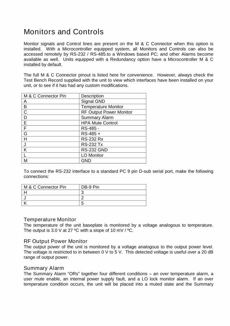
Monitor signals and Control lines are present on the M & C Connector when this option isinstalled. With a Microcontroller equipped system, all Monitors and Controls can also beaccessed remotely by RS-232 / RS-485.to a Windows based PC; and other Alarms becomeavailable as well. Units equipped with a Redundancy option have a Microcontroller M & Cinstalled by default.
The full M & C Connector pinout is listed here for convenience. However, always check theTest Bench Record supplied with the unit to view which interfaces have been installed on yourunit, or to see if it has had any custom modifications.
M & C Connector Pin DescriptionA Signal GNDB Temperature MonitorC RF Output Power MonitorD Summary AlarmE HPA Mute ControlF RS-485 -G RS-485 +H RS-232 RxJ RS-232 TxK RS-232 GNDL LO MonitorM GND
To connect the RS-232 interface to a standard PC 9 pin D-sub serial port, make the followingconnections:
M & C Connector Pin DB-9 PinH 3J 2K 5
Temperature MonitorThe temperature of the unit baseplate is monitored by a voltage analogous to temperature.The output is 3.0 V at 27 ºC with a slope of 10 mV / ºC.
RF Output Power MonitorThe output power of the unit is monitored by a voltage analogous to the output power level.The voltage is restricted to in between 0 V to 5 V. This detected voltage is useful over a 20 dBrange of output power.
Summary AlarmThe Summary Alarm “ORs” together four different conditions – an over temperature alarm, auser mute enable, an internal power supply fault, and a LO lock monitor alarm. If an overtemperature condition occurs, the unit will be placed into a muted state and the Summary

Alarm will go low (0 V). Also, if the unit is muted through the Mute Input, the Summary Alarmwill also show an alarm condition (low).
HPA Mute ControlShorting this line to Ground or applying 0 V to this line will disable the Booster Amplifiermodule. Leaving it open or applying 5 V will keep the unit enabled.
Ground (GND)This pin is connected to the chassis, which also represents the main Ground of the unit.
All the transmission equipment should be grounded at the antenna location. All cablesinterconnection outdoor equipment to indoor equipment should be grounded at the entry point.
The antenna and outdoor grounding rods should be connected to the building entry groundingrod by means of a separated grounding cable AWG 4 or thicker to avoid current loopstravelling through cables.
Equipment returned to factory with power supplies damaged due to power surges or lighteningstrikes will not be covered by warranty!
PLEASE MAKE SURE THAT THE UNIT AND CABLESARE PROPERLY GROUNDED TO AVOID DAMAGESTO THE EQUIPMENT AND RISK TO PERSONEL !!!
LO Locked/Unlocked MonitorThis alarm indicates the PLL lock status of the internal BUC module. A logic low (0 V)indicates no alarm (Local Oscillator locked), while a high (5 V) indicates a problem (LocalOscillator unlocked).
RS-232 / RS-485Available with Microcontroller equipped systems. This serial link is normally used tocommunicate with a remote PC running UPCOM TECHNOLOGIES Monitor and ControlSoftware. This enables a simple way to view / control the Monitors and Controls listed above,and also enables the functions listed below.
Normally, either RS-232 or RS-485 is available at any one time (both interfaces cannot beused simultaneously). Communication links using RS-232 are typically good up to 30 ft. (9 m)in length. Installations exceeding this length should use the RS-485, which will allow serialcontrol up to 4000 ft. (1200 m).
Monitor and Control SoftwareUPCOM TECHNOLOGIES Monitor and Control Software is provided on CD for units equippedwith an onboard Microcontroller system. A Windows based PC uses this software to remotelymonitor and control the Block Up Converters (BUC) through its serial port.
The software interface is split in two, indicating “Master Unit” and “Slave Unit”. Both sectionsare active for redundant configurations, while only one of the sections is used for stand-aloneoperation.

Various Monitors and Alarms are displayed along the left hand side of the interface. If aproblem has been detected, it will be displayed in red, and the Block Up Converters (BUC) willbe placed into a muted state.
Installation InstructionsSystem Requirements:
PC running Windows 98, Me, 2000, or XP (NT 4.0 with Service Pack 6a) Display resolution of 800 x 600 or greater Free serial port (RS-232 or RS-485) Microsoft .NET Framework.
Compatibility under Windows Vista has not been tested.
The Monitor and Control Software is located inside the Monitor854 folder on the CD. Copy thisfolder to your preferred location on your PC. The Monitor854 program requires Microsoft .NETframework (included). If this is not installed, please run "dotnetfx.exe" under the Microsoft.NET Redistributable folder on the CD.
Start the software by running “monitor854.exe”.
Status DisplayThis indicator shows the general status of the Block Up Converters (BUC) – if everything isgood, or if an error condition has occurred, or if the unit has been manually disabled by mutecontrol. Also, the operating status of a Master/Slave redundant pair is reflected.
Booster Temperature DisplayUsing the UPCOM TECHNOLOGIES Monitor and Control Software, a thermometer displaywith a numeric readout of the base-plate temperature of the unit in degrees Celsius is shown.The base-plate temperature typically experiences a 20 to 30 degree rise above ambient on thehighest power Outdoor Block Up Converters (BUC)s and 15 to 20 degree rise on lower powerunits. This display corresponds with the Temperature Monitor outlined in the analog M&Csection above.
Output Power DisplayA numeric readout of the output power level is displayed in units of dBm. The indicator iscalibrated at the factory using the middle frequency of the Block Up Converters (BUC), andhas approximately a 20 dB dynamic range. When this range is exceeded, the readout shows“Low” or “High” depending on which particular limit has been reached. This display is derivedfrom the RF Output Power Monitor signal outlined above.
Overheated AlarmThis alarm indicates when the unit’s baseplate rises above about 85 ºC, which is anoverheated condition. The unit will automatically enter into a muted state. This function hasapproximately a 20 ºC hysteresis window which will allow the Block Up Converters (BUC) tore-enable itself when the temperature is reduced by 20 ºC at the baseplate.

PS Voltages MonitorThe output voltage levels of the Power Supply are monitored and this alarm indicates whenany of them fall below a preset level. Three voltages are monitored: +12 V feeding theBooster Amplifier, +24 V going to the BUC, and –5 V from the bias assemblies attached to theBooster Amplifier. The unit will enter a muted state when this alarm is active.
Manual Control Enable/Disable and Mute InputA manual mute control can be accessed from the Enable/Disable button of the software. Notethat this control is independent of the HPA Mute Control (labeled as Mute Input in the GUI)outlined above and is accessed from the hardware M & C port. Also note that the hardwareHPA Mute Control has priority over the mute status – a Block Up Converters (BUC) placed intoa muted status by the hardware HPA Mute Control line cannot be brought out of muted statusby the software Enable/Disable button. The status of the Mute Input line is monitored anddisplayed by the software.
For systems set up for 1:1 Redundant operation, this control is also used for manuallyselecting the Active unit in a redundant pair.
PLL Status DisplayThe PLL Status reports the lock condition of the BUC module, and corresponds with the LOLocked/Unlocked Monitor described above. If the Block Up Converters (BUC) loses lock, theBlock Up Converters (BUC) is disabled and an alarm is indicated. For redundantconfigurations, make note of the Reset PLL Status Button listed below.
Mate StatusIn redundant configurations, the Mate Status indicates the mute condition of its mate. That is,the Master display shows the Slave condition, and the Slave display shows the Mastercondition.
Reset PLL Status ButtonUsed only in redundant configurations. If a LO Monitor alarm occurs, PLL Status will store thealarm until Reset PLL Status is pushed, or power is cycled to the unit.
Attenuator ControlSystem conversion gain can be changed here provided an attenuator module has beeninstalled. The range of control is from 0 dB (no attenuation applied) to 20 dB (20 dB of gainreduction) in 0.5 dB steps. The value may be stepped up or down, or entered directly with thekeyboard by highlighting the entry field. Note that this control is dependent on an installedhardware option. If it is not installed, this control will not have any effect.
Temperature CompensationTighter temperature compensation response is also possible with the attenuator moduleinstalled. There is no user control here, and the unit must have the requisite hardware optioninstalled, and be calibrated at the factory for this function to be active.

Communication StatusThe communication status between the software and the Block Up Converters (BUC) isreflected here. If there is a problem here, double-check all serial port connections and ensurethe correct Com port is selected (the software uses the Select Port menu item).
Menu ItemsUnder the File menu item, there is a set of calibration routines exposed to the user. These areintended for factory use only. No support will be provided if any of these settings are adjusted.
Under the Select Port menu item, your appropriate Com port is selected for serialcommunication to the Block Up Converters (BUC).

Quick Start Guide
Connect the L Band / 10 MHz Reference to the labeled port. Nominal IF input levels areapproximately -28 dBm depending on the output power level of the unit. The 10 MHzReference must be in the range of –5 dBm to +5 dBm. Note that the Block UpConverters (BUC) will be in a mute state with the Reference signal absent.
The Block Up Converters (BUC)’s output is taken from the waveguide port (RF Out).Caution should be observed here to make sure that the antenna or a suitabletermination is connected to this port before operating the Block Up Converters (BUC).
Ensure there is proper clearance around the unit. Connect AC Input power to the connector. The unit will be enabled almost immediately,
provided it is not forced into a mute state. Optional - Connect the M & C interface to an available COM port on your computer
and/or to your analog based monitoring and control equipment. Optional - Install the Windows based Monitor and Control Program from the supplied
CD. Optional - Run the UPCOM TECHNOLOGIES Monitor and Control Program.
Review Appendix A for additional information on setting up a Redundant System.

General Maintenance
With proper care and maintenance, your Block Up Converters (BUC) will provide many yearsof reliable service. Please follow these maintenance guidelines so that your equipment willprovide you with the maximum amount of trouble-free service.
Basic CleanlinessThe exterior chassis of the Block Up Converters (BUC) acts as a large heatsink that mustdissipate at least a few hundred Watts. Excessive dirt, dust, debris, and sand accumulated onthe chassis surface will impede its ability to dissipate heat, and will result in higher internaltemperatures, potentially shortening the Block Up Converters (BUC)’s lifespan.
Periodically inspect the chassis for excessive dirt, and remove as necessary. A brushcombined with compressed air is the safest way to clean the unit. Also, inspect the fanassembly for any dirt or debris that also might impede airflow.
Internal FuseThe internal power supply is protected by a fuse to prevent excessive input currentconsumption. Contact the factory if you suspect the internal fuse has tripped, and instructionswill be sent on how it can be replaced.
Fan Inspection and Replacement
Normally the fan on the unit operates continuously when input power is connected to the unit.If the fan stops turning, and the Block Up Converters (BUC) still provides an output signalwhen it is cool, it is time to replace the fan. Immediately remove power to the unit the preventdamage by overheating.
Periodical inspection of the status of the fan is a major priority in the preventivemaintenance of the unit. If the fan is dirty it should be cleaned. Special care should betaken in environments with high level of fine sand, such as deserts .
If possible, assemble the unit with the fans “looking” down to avoid debris, dust andsand deposits.
The user should inspect the fans on a monthly basis and determine when it’srecommendable to replace the fan. Periodical cleaning or replacement of the fans is asmall cost compared to the repair of an amplifier inside the unit.
Contact the factory to order the correct replacement fan for your particular model.
The fan is encased in a shroud to direct airflow to the chassis heat sink fins. First remove theshroud from the main chassis using the screws at each side of the chassis. The fan andshroud assembly will be connected by wires to the main chassis. Disconnect the wireconnection by pulling apart the inline (wire to wire) connector.
Next, remove the screws holding the fan to the shroud and fan grille. Remove the fan, andinstall the replacement fan in reverse order as described above.

Theory of Operation
AC / DC ConverterThe prime AC input power is delivered to a converter module that produces 300 VDC. Thismodule is an auto-sensing front end that has proven reliability and allows the amplifier systemto operate over a wide variety of input power conditions encountered around the world.
DC / DC ConverterThe DC/DC converter module is a switched mode power supply that converts the 300 VDC to12 VDC. This 12 VDC is the primary high current, DC voltage source that operates the boosteramplifier module.A secondary module converts the 300 VDC to 24 VDC. This source powers the BlockUpconverter and the Cooling System.
Units with input AC power use the above AC / DC and DC / DC topology. Units with DC inputuse a single DC / DC converter stage to convert from the input supply voltage to the system’srequired 12 VDC and 24 VDC.
Cooling SystemThe Outdoor Block Up Converters (BUC)’s cooling system represents a landmark inmicrowave telecommunication amplifiers. It is a unique system of heat sinks that have beencomputer optimized to provide extremely efficient cooling of all of the system’s functionalblocks. This high efficiency cooling system is primarily responsible for the small overallpackage size and reduced weight of the unit.The Cooling System is based on a forced convection technique in which both system fansprovide the air intake while the exhaust is brought out around the outer perimeter of the fans.The fan is up to 300 CFM rated and operate into approximately 0.3 in. H20 back pressure. It isalso weather protected for reliability under a variety of conditions.
Block UpconverterThe Block Upconverter (BUC) takes an L Band input, and through a single frequencytranslation, converts the signal to the final output frequency (C or Ku Band). The BUC locksonto an input 10 MHz reference signal to provide the final output frequency. The conversiongain for this sub-section is in the neighborhood of 55 dB.
Booster AmplifierThis module uses GaAs MESFET technology to boost the signal level to its final output powerlevel. A bias assembly connects the +12 V power supply with the FETs, and provides properbias voltages (including the negative voltage for the FET gates), and voltage sequencing atturn on and turn off. The gain for this section is in the neighborhood of 20 dB.
MicrocontrollerThis section is responsible for serial communications and for processing of the Monitors andControls. Various alarms are monitored, such as overheating and PLL lock alarms, along withselect DC voltages. The microcontroller disables the Block Up Converters (BUC) when any ofthese status indicators show a problem. In addition, it is possible for the microcontroller toreport output power levels in dBm and control system conversion gain (when appropriatehardware is installed).

In Redundant configured units, the Microcontroller is also responsible for system switchingbehavior.
Attenuator ModuleThis is an electrically controlled variable attenuator – an optional component that generallyreceives control signals from the Microcontroller. It is responsible for both gain controlfunctions and supplemental gain versus temperature compensation.
Dual Transfer SwitchSupplied only with Redundant Systems. It is a dual switch with a coaxial section and awaveguide section. The coaxial section is used to transfer the input signal to either Master orSlave, and the waveguide section is used to transfer the output signal from either Master orSlave. Port 3 is terminated on both coaxial and waveguide sections, Port 4 connects to theMaster, and Port 2 connects to the Slave. Coaxial Port 1 acts as the system input, andWaveguide Port 1 acts as the system output.
A manual switch position knob is present, but this should normally never be used when thesystem is connected and powered up.

Appendix A
Installation Notes for Redundant System
The redundant system is composed of the following items:1. 2 outdoor Block Up Converters (BUC) units, each configurable between Master or Slave
(or M / S). Note that older units may be internally hardwired for Master/Slave operationand cannot be changed.
2. 1 waveguide dual switch assembly.3. 1 redundant port cable assembly (3 connector Y assembly).4. 2 input cable assemblies.
Assemble the Block Up Converters (BUC) units onto your support bracketing (may not besupplied). Use the toggle switch on the unit to select either Master or Slave operation mode(M or S). The Redundant System must have precisely 1 Master and 1 Slave. Make note ofwhich unit is the Master and which is the Slave.
Before making any connections, ensure that all ports and interfaces have all plastic covers orprotective films (tape) removed.
Using the waveguide dual switch assembly, check the alignment of the RF Out ports on theBlock Up Converters (BUC)s, and adjust as necessary.
Waveguide Port 4 of the switch attaches to the RF Out port of the Master. Waveguide Port 2 of the switch attaches to the RF Out port of the Slave. Waveguide Port 3 is terminated. Waveguide Port 1 acts as the redundant system output.
Connect the 2 IF input cable assemblies and other coaxial connections: Coaxial Port 4 of the switch connects to the IF Input port of the Master. Coaxial Port 2 of the switch connects to the IF Input port of the Slave. Coaxial Port 3 is terminated. Coaxial Port 1 acts as the redundant system input.
Connect the redundant port cable assembly: Attach J1 to the Master Redundancy / RF Switch Port. Attach J2 to the Slave Redundancy / RF Switch Port. Attach J3 to the waveguide switch (circular connector).
When using the serial port interface, it is recommended to only connect to the Master UnitM&C Port. Both Master and Slave unit can be accessed through the software GUI in this wayusing a single connection.
The input to the redundant system is Coaxial Port 1 of the switch, and the output is WaveguidePort 1 of the switch.


COMPANY CONFIDENTIALThis document is the property of UPCOM TECHNOLOGIES and may be neither used, copied, nor
reproduced outside of the company. Nor may its contents be communicated outside of the company, exceptwith the written permission ofUPCOM TECHNOLOGIES
AC[1..3]
IF In RF Out
M&C[1..17]
Red[1..10]
U1
Master BUC
AC[1..3]
IF In RF Out
M&C[1..17]
Red[1..10]
U2
Slave BUC
C1
C2
C3
C4
S1-C-1Transfer Switch
W1
W2
W3
W4
S1-WG-2Transfer Switch
Circ[1..19]
S1-Port-3Transfer Switch
R1Termination
R2Termination
IF In / 10 MHz Ref In RF Out
AC In Master [1..3]
AC In Slave [1..3]
Serial / M&C [1..17]
J1
J2
J3
Y Cable