user guide, ireport - motion control engineering · ireport is a system logging and report...
TRANSCRIPT

Motion Control Engineering, Inc.11380 White Rock RoadRancho Cordova, CA 95742
voice 916 463 9200fax 916 463 9201www.mceinc.com
User Guide,iReport
Manual # 42-02-S026, Rev A3, September 2008
Copyright© 2008, Motion Control Engineering. All Rights Reserved.This document may not be reproduced, electronically or mechanically, in whole or in part, without written permission from Motion Control Engineering.
TrademarksAll trademarks or registered product names appearing in this document are the exclusive property of the respective owners.
Warning and DisclaimerAlthough every effort has been made to make this document as complete and accurate as possible, Motion Control Engineering and the document authors, publishers, distributors, and representatives have neither liability nor responsibility for any loss or damage arising from information contained in this document or from informational errors or omissions. Information contained in this document shall not be deemed to constitute a commitment to provide service, equipment, or software by Motion Control Engineering or the document authors, publishers, distributors, or representatives.
Limited WarrantyMotion Control Engineering (manufacturer) warrants its products for a period of 15 months from the date of shipment from its factory to be free from defects in workmanship and materials. Any defect appearing more than 15 months from the date of shipment from the factory shall be deemed to be due to ordinary wear and tear. Manufacturer, however, assumes no risk or liability for results of the use of the products purchased from it, including, but without limiting the generality of the forgoing: (1) The use in combination with any electrical or electronic components, circuits, systems, assemblies or any other material or equipment (2) Unsuitability of this product for use in any circuit, assembly or environment. Purchasers’ rights under this warranty shall consist solely of requiring the manufacturer to repair, or in manufacturer's sole discretion, replace free of charge, F.O.B. factory, any defective items received at said factory within the said 15 months and determined by manufacturer to be defective. The giving of or failure to give any advice or recommendation by manufacturer shall not constitute any warranty by or impose any liability upon the manufacturer. This warranty constitutes the sole and exclusive remedy of the purchaser and the exclusive liability of the manufacturer, AND IN LIEU OF ANY AND ALL OTHER WARRANTIES, EXPRESSED, IMPLIED, OR STATUTORY AS TO MERCHANTABILITY, FITNESS, FOR PURPOSE SOLD, DESCRIPTION, QUALITY PRODUCTIVENESS OR ANY OTHER MATTER. In no event will the manufacturer be liable for special or consequential damages or for delay in performance of this warranty.
Products that are not manufactured by MCE (such as drives, CRTs, modems, printers, etc.) are not covered under the above warranty terms. MCE, however, extends the same warranty terms that the original manufacturer of such equipment provide with their product (refer to the warranty terms for such products in their respective manual).

End User License AgreementThis End User License Agreement (“Agreement”) grants you the right to use the software con-
tained in this product (the “Software”) subject to the following restrictions: You may not: (i) copy
the Software, except for archive purposes consistent with your standard archive procedures; (ii)
transfer the Software to a third party apart from the entire product; (iii) modify, decompile, disas-
semble, reverse engineer or otherwise attempt to derive the source code of the Software; (iv)
export the Software or underlying technology in contravention of applicable U.S. and foreign
export laws and regulations; and (v) use the Software other than in connection with operation of
the product.
“LICENSOR'S SUPPLIERS DO NOT MAKE OR PASS ON TO END USER OR ANY OTHER THIRD PARTY,
ANY EXPRESS, IMPLIED OR STATUTORY WARRANTY OR REPRESENTATION ON BEHALF OF SUCH
SUPPLIERS, INCLUDING BUT NOT LIMITED TO THE IMPLIED WARRANTIES OF NON-INFRINGE-
MENT, TITLE, MERCHANTABILITY OR FITNESS FOR A PARTICULAR PURPOSE.”

Important Precautions and Useful InformationThis preface contains information that will help you understand and safely maintain MCE equipment. We strongly recommend you review this preface and read this manual before installing, adjusting, or maintaining Motion Control Engineering equipment. This preface dis-cusses:
• Safety and Other Symbol Meanings
• In This Guide
Safety and Other Symbol Meanings
DangerThis manual symbol is used to alert you to procedures, instructions, or situations which, if not done properly, might result in personal injury or substantial equipment damage.
CautionThis manual symbol is used to alert you to procedures, instructions, or situations which, if not done properly, might result in equipment damage.
Note
This manual symbol is used to alert you to instructions or other immediately helpful information.
In This Manual:This manual is the installation and operation guide for iReport. When viewed online as a pdf file, hyperlinks link to related topics and informational websites. The manual includes:
• Contents: Table of Contents. When viewed online as a pdf file, hyperlinks in the Contents link to the associated topic in the manual.
• Section 1. iReport general description and installation instructions.
• Section 2. Reference: Detailed explanation of screen controls.
• Index: Alphabetical index to help you find information in the manual. When viewed online as a pdf file, index entry page references are hyperlinks to the associated informa-tion in the manual.
Contents
Section 1. iReportiReport . . . . . . . . . . . . . . . . . . . . . . . . . . . . . . . . . . . . . . . . . . . . . . . . . . . . . . . . . . . . 1-1
System Description . . . . . . . . . . . . . . . . . . . . . . . . . . . . . . . . . . . . . . . . . . . . . . . . . 1-2
Installation . . . . . . . . . . . . . . . . . . . . . . . . . . . . . . . . . . . . . . . . . . . . . . . . . . . . . . . . 1-4Hardware Install . . . . . . . . . . . . . . . . . . . . . . . . . . . . . . . . . . . . . . . . . . . . . . . . . . . . . . . . . . . 1-4
Making Connections . . . . . . . . . . . . . . . . . . . . . . . . . . . . . . . . . . . . . . . . . . . . . . . . . . . . . . 1-4Establishing Connections . . . . . . . . . . . . . . . . . . . . . . . . . . . . . . . . . . . . . . . . . . . . . . . . . . . . .1-5
MCE Elevator Ethernet . . . . . . . . . . . . . . . . . . . . . . . . . . . . . . . . . . . . . . . . . . . . . . . . . . . . 1-5iControl Local Connection . . . . . . . . . . . . . . . . . . . . . . . . . . . . . . . . . . . . . . . . . . . . . . . . . . . 1-8
One Group . . . . . . . . . . . . . . . . . . . . . . . . . . . . . . . . . . . . . . . . . . . . . . . . . . . . . . . . . . . . . . 1-8Restrictions. . . . . . . . . . . . . . . . . . . . . . . . . . . . . . . . . . . . . . . . . . . . . . . . . . . . . . . . . . . . . . 1-8
Multiple Machine Rooms / Dedicated Elevator LAN . . . . . . . . . . . . . . . . . . . . . . . . . . . . . 1-9Restrictions. . . . . . . . . . . . . . . . . . . . . . . . . . . . . . . . . . . . . . . . . . . . . . . . . . . . . . . . . . . . . . 1-9
Multiple Machine Rooms with Existing Building LAN . . . . . . . . . . . . . . . . . . . . . . . . . . . .1-10Restrictions. . . . . . . . . . . . . . . . . . . . . . . . . . . . . . . . . . . . . . . . . . . . . . . . . . . . . . . . . . . . . 1-11
Two or More Buildings . . . . . . . . . . . . . . . . . . . . . . . . . . . . . . . . . . . . . . . . . . . . . . . . . . . . . .1-12
Remote Connection . . . . . . . . . . . . . . . . . . . . . . . . . . . . . . . . . . . . . . . . . . . . . . . . 1-13Software Install . . . . . . . . . . . . . . . . . . . . . . . . . . . . . . . . . . . . . . . . . . . . . . . . . . . . . . . . . . . .1-14
iReport Server Software . . . . . . . . . . . . . . . . . . . . . . . . . . . . . . . . . . . . . . . . . . . . . . . . . . 1-14iReport Client Software. . . . . . . . . . . . . . . . . . . . . . . . . . . . . . . . . . . . . . . . . . . . . . . . . . . 1-16
Startup . . . . . . . . . . . . . . . . . . . . . . . . . . . . . . . . . . . . . . . . . . . . . . . . . . . . . . . . . . . 1-17
v
Section 2. ReferenceReference . . . . . . . . . . . . . . . . . . . . . . . . . . . . . . . . . . . . . . . . . . . . . . . . . . . . . . . . . 2-1
Opening iReport . . . . . . . . . . . . . . . . . . . . . . . . . . . . . . . . . . . . . . . . . . . . . . . . . . . .2-2
File Menu . . . . . . . . . . . . . . . . . . . . . . . . . . . . . . . . . . . . . . . . . . . . . . . . . . . . . . . . . .2-3Edit Dispatchers . . . . . . . . . . . . . . . . . . . . . . . . . . . . . . . . . . . . . . . . . . . . . . . . . . . . . . . . . . . . 2-4
Important Edit Connection Information . . . . . . . . . . . . . . . . . . . . . . . . . . . . . . . . . . . . . 2-5Alternate Connections. . . . . . . . . . . . . . . . . . . . . . . . . . . . . . . . . . . . . . . . . . . . . . . . . . . . . 2-5
Print and Import/Export . . . . . . . . . . . . . . . . . . . . . . . . . . . . . . . . . . . . . . . . . . . . . . . . . . . . 2-5Notification . . . . . . . . . . . . . . . . . . . . . . . . . . . . . . . . . . . . . . . . . . . . . . . . . . . . . . . . . . . . . . . . 2-6
Adding persons to be notified. . . . . . . . . . . . . . . . . . . . . . . . . . . . . . . . . . . . . . . . . . . . . . . . . . . . 2-7Add an SMTP server . . . . . . . . . . . . . . . . . . . . . . . . . . . . . . . . . . . . . . . . . . . . . . . . . . . . . . . . . . . 2-9
Remaining File Menu Choices . . . . . . . . . . . . . . . . . . . . . . . . . . . . . . . . . . . . . . . . . . . . . . . . 2-9
Reports Menu . . . . . . . . . . . . . . . . . . . . . . . . . . . . . . . . . . . . . . . . . . . . . . . . . . . . .2-10Hall Call Performance . . . . . . . . . . . . . . . . . . . . . . . . . . . . . . . . . . . . . . . . . . . . . . . . . . . . . . 2-12Hall Call Analysis . . . . . . . . . . . . . . . . . . . . . . . . . . . . . . . . . . . . . . . . . . . . . . . . . . . . . . . . . . 2-13Traffic Analysis . . . . . . . . . . . . . . . . . . . . . . . . . . . . . . . . . . . . . . . . . . . . . . . . . . . . . . . . . . . . 2-14Hall Call Log . . . . . . . . . . . . . . . . . . . . . . . . . . . . . . . . . . . . . . . . . . . . . . . . . . . . . . . . . . . . . . 2-15Car Call Log . . . . . . . . . . . . . . . . . . . . . . . . . . . . . . . . . . . . . . . . . . . . . . . . . . . . . . . . . . . . . . 2-16Security Call Log . . . . . . . . . . . . . . . . . . . . . . . . . . . . . . . . . . . . . . . . . . . . . . . . . . . . . . . . . . .2-17Event Log . . . . . . . . . . . . . . . . . . . . . . . . . . . . . . . . . . . . . . . . . . . . . . . . . . . . . . . . . . . . . . . . 2-18Emergency Log . . . . . . . . . . . . . . . . . . . . . . . . . . . . . . . . . . . . . . . . . . . . . . . . . . . . . . . . . . . . 2-19Maintenance Log . . . . . . . . . . . . . . . . . . . . . . . . . . . . . . . . . . . . . . . . . . . . . . . . . . . . . . . . . . 2-20
Management/Entries. . . . . . . . . . . . . . . . . . . . . . . . . . . . . . . . . . . . . . . . . . . . . . . . . . . . . . . . . .2-20Percent in Service . . . . . . . . . . . . . . . . . . . . . . . . . . . . . . . . . . . . . . . . . . . . . . . . . . . . . . . . . . 2-21
Help Menu . . . . . . . . . . . . . . . . . . . . . . . . . . . . . . . . . . . . . . . . . . . . . . . . . . . . . . . . 2-21
vi Manual # 42-02-S026, 9/23/08

1
• iReport• System Description• Installation• Startup
iReport
iReportiReport is a system logging and report generating tool that allows local or remote analysis of elevator groups from a personal computer running the Windows XP operating system and iReport client software. Dispatchers must be Ethernet capa-ble, so you can use iReport to connect to them through a local area network or remotely through internet/modem technology.
iControl systems have a standard Ethernet interface, other MCE systems will need optional Ethernet hardware and system software upgrades to support iReport.
This manual section describes:
• System Description
• Installation
• Startup
Note
This manual describes all iReport software features. If you are connected to a controller other than an iControl, not all features will be supported by your controller.
1-1

iReport
System DescriptioniReport consists of the iReport server and iReport clients. Group dispatchers may be connected to iReport directly through a local area network or they may be connected remotely through a DSL or other high-speed connection and the internet. The group dispatcher provides iReport with hall call and car operating mode information. The individual car controllers provide iRe-port with event and fault notifications.
You connect to and use iReport through the iReport client program on your PC. The block dia-gram below illustrates a possible system interconnection. Various local and remote connections are possible depending upon system requirements.
Figure 1.1 iReport Simplified Block Diagram
Internet
Database
Web Server
iReport Interface
iReport Client
iReport ClientiReportSERVER
Call Data,Operating mode,
Faults, Events
CONTROLLER CONTROLLER CONTROLLER
iCENTRAL / iCUE
LAN
ReportPRINTER
DSL
DSL
1-2 Manual # 42-02-S026
System Description
1
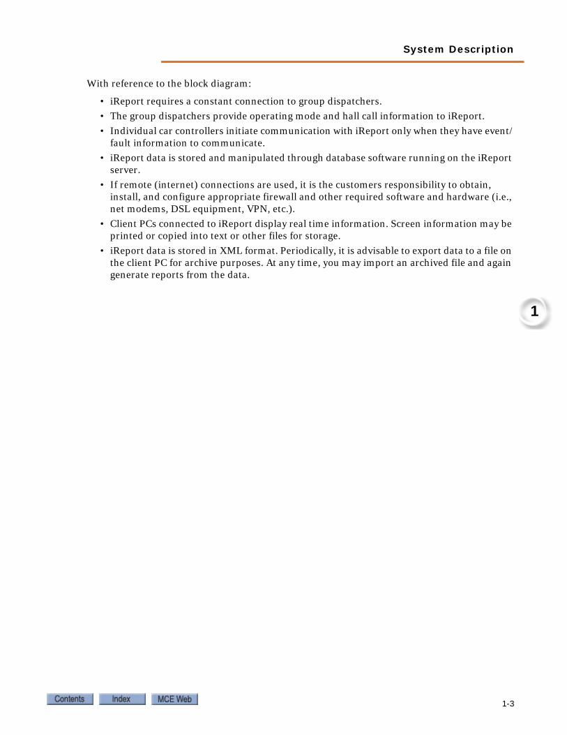
With reference to the block diagram:
• iReport requires a constant connection to group dispatchers.
• The group dispatchers provide operating mode and hall call information to iReport.
• Individual car controllers initiate communication with iReport only when they have event/fault information to communicate.
• iReport data is stored and manipulated through database software running on the iReport server.
• If remote (internet) connections are used, it is the customers responsibility to obtain, install, and configure appropriate firewall and other required software and hardware (i.e., net modems, DSL equipment, VPN, etc.).
• Client PCs connected to iReport display real time information. Screen information may be printed or copied into text or other files for storage.
• iReport data is stored in XML format. Periodically, it is advisable to export data to a file on the client PC for archive purposes. At any time, you may import an archived file and again generate reports from the data.
1-3

iReport
InstallationInstallation includes hardware and software installs. If you purchased your iReport server from MCE, all required server software has already been installed. In this case, you need only follow hardware installation, iReport Client software installation, and startup instructions to begin using iReport. Refer to the MCE Elevator Ethernet topic and connection examples provided in the following pages of this guide.
Hardware InstallThe iReport server and iReport client PCs connect to the iCue/iCentral group dispatcher LAN hub. For local network connection:
1. The Ethernet cable provided to connect the iReport server to the group dispatcher is 25-feet long unless otherwise specified. Making sure the cable length is sufficient, install the server, monitor, keyboard, and mouse as described in the server manufacturer docu-mentation.
2. Connect the blue Ethernet cable provided between the iReport server TCP/IP port and an unused port on the iCue/iCentral LAN hub.
3. Set up the PC that will run the iReport Client software and connect it to an unused ports on the iCue/iCentral LAN hub.
Note
If multiple elevator group dispatchers are interconnected. The iReport server and Client PCs may be con-nected to the LAN hub of any of the interconnected groups.
Making ConnectionsIf the iReport server and/or client PCs are located at a different site than the iCue/iCentral group dispatcher to be monitored, you will need additional hardware and software to set up connections between machines.
If the server and PCs are on the same site but located too distantly for direct connection to the iCue LAN hub, you may be able to use ethernet extenders that allow the range of the network connections to be extended. Equipment to accomplish this is available at most commercial elec-tronics stores. If your order included MCE Expanded Network equipment, consult the instructions that accompanied that equipment for installation guidance.
If the server and/or PCs are located at another site, you will need to establish connection using DSL modems and will need to install and configure firewall software to protect the elevator net-work from unauthorized intrusions. The MCE Remote Connect product may be used to facili-tate these connections. In any case, you will probably need to employ the services of a networking specialist to properly set up these connections.
Note
If you are setting up remote connections, there are many commercial products available to complete the job. Unless you are very knowledgeable about networking, this task should be left to a professional.
1-4 Manual # 42-02-S026

Installation
1
Establishing ConnectionsThe iReport server and Client PCs may be connected to elevator group controllers locally or remotely through the internet.
MCE Elevator EthernetMCE iCue elevator group controls use two local Ethernet networks. The first of these, the Sys-tem network, is only used for immediate elevator traffic control. No external connections may be made to this network. This network uses orange cabling to set it apart from the second, LAN network (blue cabling).
The LAN network provides the point of connection for both the iReport server and Client PCs. You can identify the Ethernet hub for the iView network by checking:
• The hub is labeled “LAN.” Connections from the hub to the individual iControl elevators in the group are plugged into the #1 = LAN connection on the iControls.
• The iView PC for the group is connected to this hub.
• The connection from the hub to the iCue Group control is to the group control LAN con-nection.
Your job prints provide specific information about address settings and connections for your installation, please refer to them. The factory-default TCP/IP information for iCue/iControl ele-vator groups is:
The default Subnet Mask for all ports is 255.255.255.000.
The default Gateway for the #1 (LAN) is 192.168.191.254.
Table 1.1 LAN Addresses
Hub Group Group IP Primary & Backup Car ID Car IP Free
LAN A 192.168.191.201-202 1-20 192.168.191.001-020 192.168.191.101-200
LAN B 192.168.191.203-204 1-20 192.168.191.021-040 192.168.191.101-200
LAN C 192.168.191.205-206 1-20 192.168.191.041-060 192.168.191.101-200
LAN D 192.168.191.207-208 1-20 192.168.191.061-080 192.168.191.101-200
LAN E 192.168.191.209-210 1-20 192.168.191.081-100 192.168.191.101-200
1-5
iReport
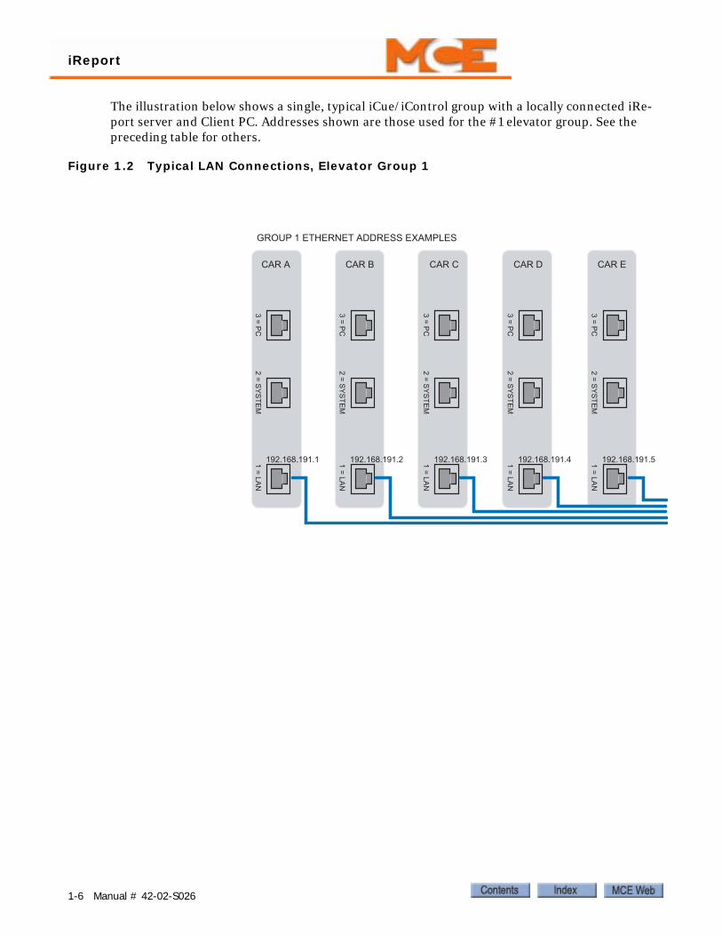
The illustration below shows a single, typical iCue/iControl group with a locally connected iRe-port server and Client PC. Addresses shown are those used for the #1 elevator group. See the preceding table for others.
Figure 1.2 Typical LAN Connections, Elevator Group 1
192.168.191.1
CAR A
192.168.191.2
CAR B
192.168.191.3
CAR C
192.168.191.4
CAR D
192.168.191.5
CAR E
GROUP 1 ETHERNET ADDRESS EXAMPLES
1-6 Manual # 42-02-S026

Installation
1
192519
LAN HUB
iCue Group Controller
2.168.191.1015.255.255.0 Subnet Mask2.168.191.254 Gateway
192.168.191.102255.255.255.0 Subnet Mask192.168.191.254 Gateway
192.168.191.103255.255.255.0 Subnet Mask192.168.191.254 Gateway
PC used for LAN Connection iReport Server
iReport Client
iView, LAN
BLUE CABLES
iCue SYSTEM192.168.192.201255.255.255.0 Subnet Mask0.0.0.0 Gateway
iCue LAN192.168.191.201255.255.255.0 Subnet Mask192.168.191.254 Gateway
1-7

iReport
iControl Local ConnectionLocal connections are those not requiring a VPN.
One GroupThe following illustration shows a same-site iReport installation for a single group.
Figure 1.3 Local Connection to Single Group
Restrictions• No single Ethernet cable may be longer than 100m (328 feet).
• If any single cable run will exceed 100m, an Ethernet hyperextender or fiber-optic to Ethernet converters must be used.
• All IP addresses on an interconnected network must be unique.
• Use shielded CAT 5e or CAT 6 STP (shielded twisted pair) cable and follow all manufac-turer recommendations.
iControl iControl iControl
iMonitor/iReport Client PCiReport Server PC
LAN Switch
Switch
iCue
1-8 Manual # 42-02-S026

Installation
1
Multiple Machine Rooms / Dedicated Elevator LANFigure 1.4 Multiple Machine Rooms / Dedicated Elevator LAN
RestrictionsAs with single group connections.
iControl iControl iControl
iCue
LAN Switch
iMonitor Switch
iControl iControl iControl
iCue
LAN Switch
iControl iControl iControl
iCue
LAN Switch
Mid Rise Group
High Rise Group
Low Rise Group
iMonitor/iReport Client PCiReport Server PC
1-9
iReport
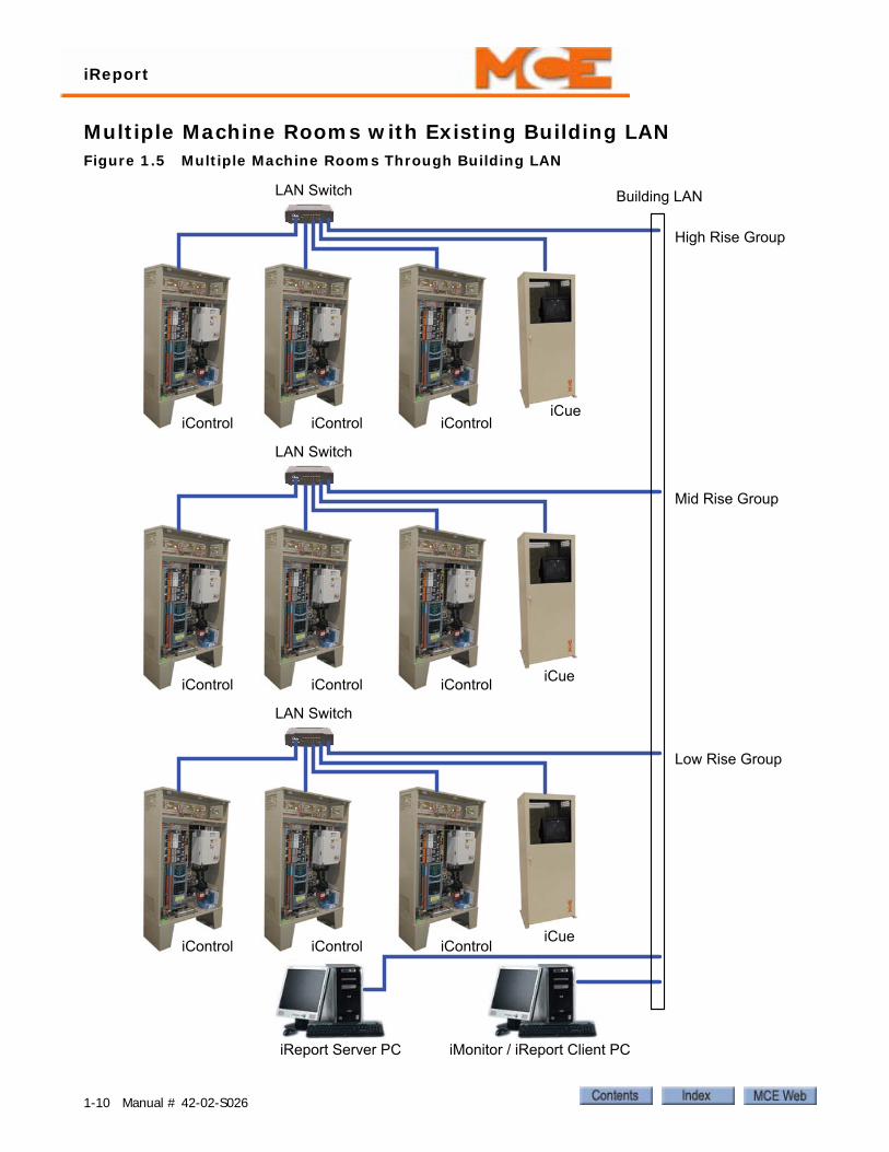
Multiple Machine Rooms with Existing Building LANFigure 1.5 Multiple Machine Rooms Through Building LAN
High Rise Group
iControl iControl iControl
iCue
LAN Switch Building LAN
iControl iControl iControl
iCue
LAN Switch
iControl iControl iControl
iCue
LAN Switch
Mid Rise Group
Low Rise Group
iMonitor / iReport Client PCiReport Server PC
1-10 Manual # 42-02-S026
Installation
1
RestrictionsIn the previous example, each group LAN switch is connected to a cable drop or Ethernet port located in the machine room. Each machine room and the iReport Client station should be “cross-connected” by the building IT department. It is good practice to isolate the elevator net-work on its own VLAN if practical.
To facilitate this type of connectivity, each device connected to the network needs a static IP address:
• iBox
• iCue PC
• iView PC
• iMonitor PC
• iReport Server PC
The building IT department should provide a static IP address for each device. DHCP can be used for the iMonitor / iReport Client PC only. Please obtain the following from the building IT department:
• IP address
• Subnet mask
• Gateway
Enter the address information into the LAN address of each iBox, as well as the LAN address of each iCue. Also change the IP address for each iView, iMonitor / iReport Client, and iReport Server PC.
1-11
iReport
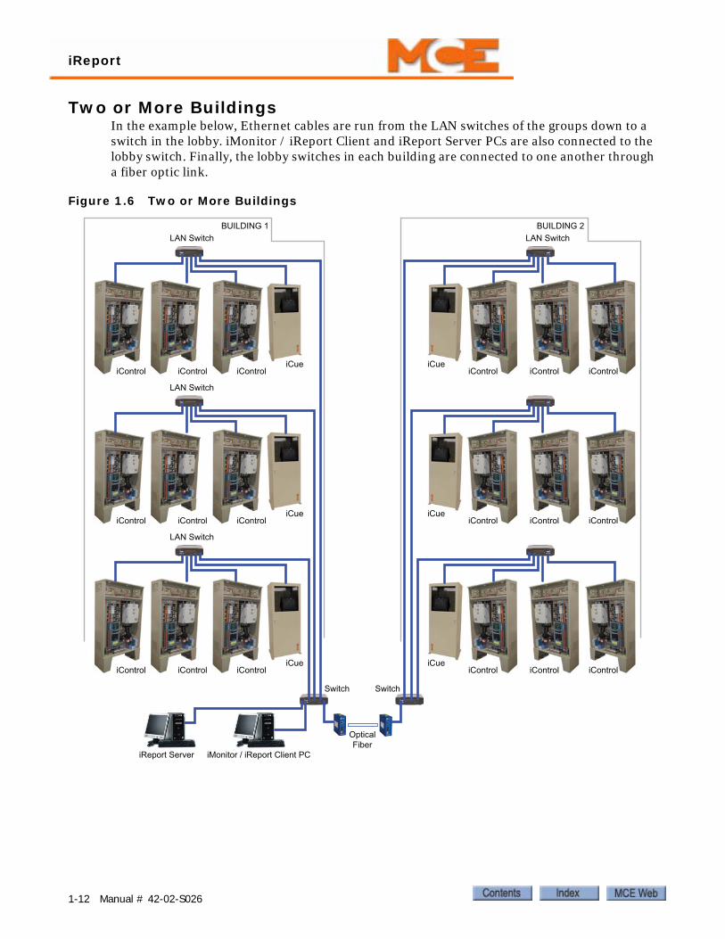
Two or More BuildingsIn the example below, Ethernet cables are run from the LAN switches of the groups down to a switch in the lobby. iMonitor / iReport Client and iReport Server PCs are also connected to the lobby switch. Finally, the lobby switches in each building are connected to one another through a fiber optic link.
Figure 1.6 Two or More Buildings
BUILDING 1 BUILDING 2
iControl iControl iControliCue
LAN Switch LAN Switch
SwitchSwitch
OpticalFiber
iControl iControl iControliCue
LAN Switch
iControl iControl iControliCue
LAN Switch
iMonitor / iReport Client PCiReport Server
iCue
iCue
iCue
iControl iControl iControl
iControl iControl iControl
iControl iControl iControl
1-12 Manual # 42-02-S026
Remote Connection
1
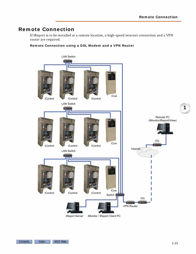
Remote ConnectionIf iReport is to be installed at a remote location, a high-speed internet connection and a VPN router are required.
Remote Connection using a DSL Modem and a VPN Router
iControl iControl iControliCue
LAN Switch
iControl iControl iControliCue
LAN Switch
iControl iControl iControliCue
LAN Switch
Switch
VPN Router
iReport Server iMonitor / iReport Client PC
Remote PC(iMonitor/iReport/iView)
DSL
DSL
Internet
1-13
iReport
Software InstallThe iReport server requires server and database software. Typically, this software is installed on your preconfigured iReport Server. Server software install instructions are included here for reference if required. If you are installing from a CD, there will be an install instructions file on the CD specific to the release version. If available, the CD instructions should be followed rather than the instructions here.
iReport client software must be installed on PCs used to connect to the iReport server. If you purchased your client PCs from MCE, this software is installed for you. If you are using client PCs from another source, you must install the iReport Client software.
iReport Server Software1. Copy the iReport Server folder from the CD or web site to the server desktop. This is a
required step.2. Open the folder and double-click the LaunchSetup.exe file.
If a dialog appears and asks you to install the .NET Framework, click Yes and follow on-screen instructions to complete .NET installation.
3. When unpacking has finished, a dialog will ask you to accept the terms of agreement. After you accept, continue with setup to install the .NET Framework (if it has not already been installed).
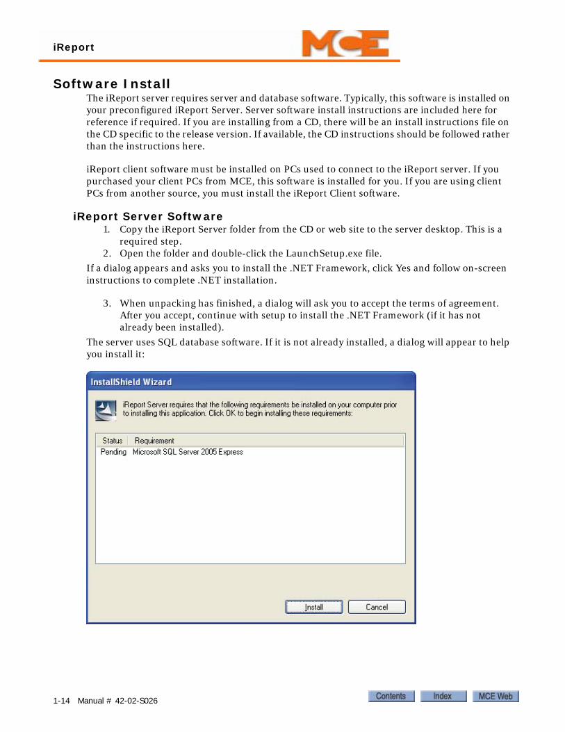
The server uses SQL database software. If it is not already installed, a dialog will appear to help you install it:
1-14 Manual # 42-02-S026
Remote Connection
1
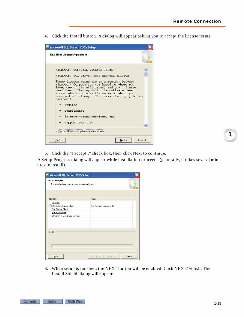
4. Click the Install button. A dialog will appear asking you to accept the license terms.
5. Click the “I accept..” check box, then click Next to continue.
A Setup Progress dialog will appear while installation proceeds (generally, it takes several min-utes to install).
6. When setup is finished, the NEXT button will be enabled. Click NEXT/Finish. The Install Shield dialog will appear.
1-15
iReport
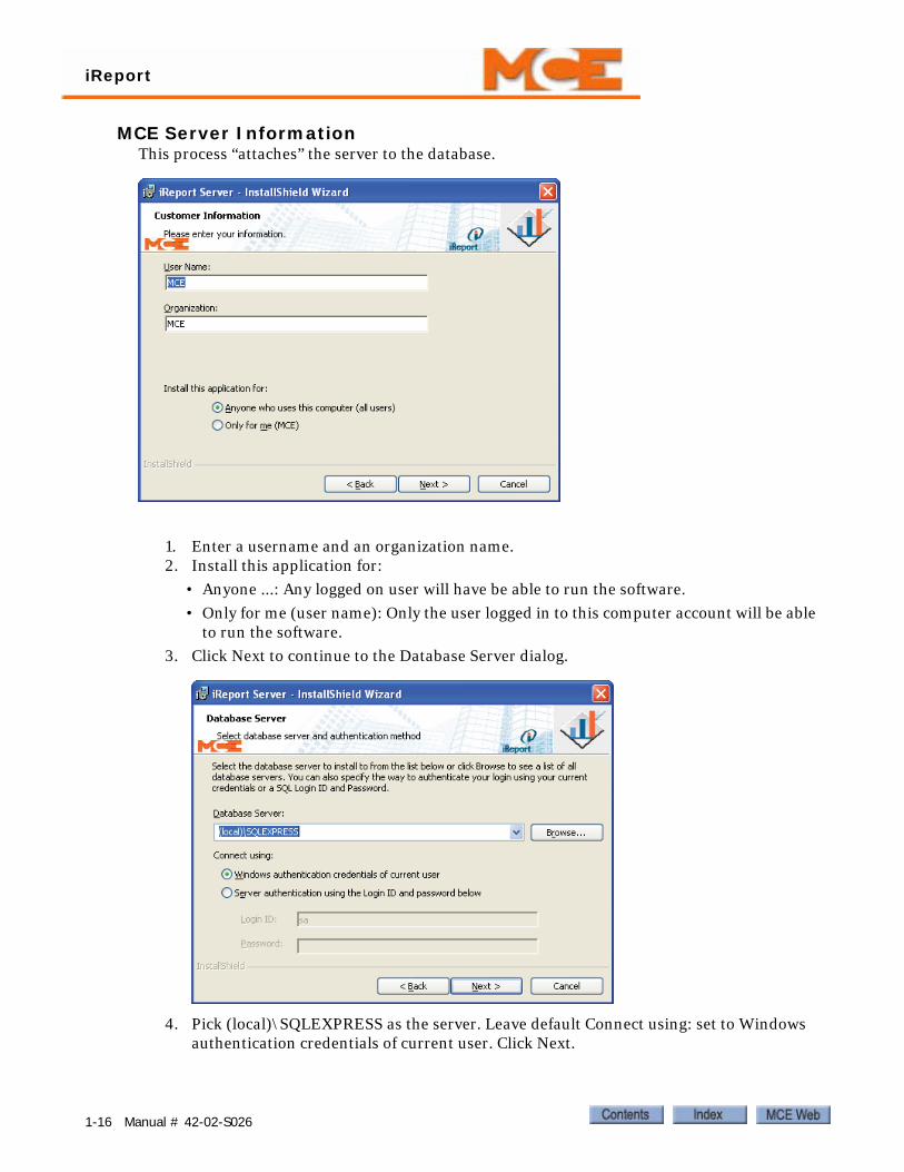
MCE Server InformationThis process “attaches” the server to the database.
1. Enter a username and an organization name.2. Install this application for:
• Anyone ...: Any logged on user will have be able to run the software.
• Only for me (user name): Only the user logged in to this computer account will be able to run the software.
3. Click Next to continue to the Database Server dialog.
4. Pick (local)\SQLEXPRESS as the server. Leave default Connect using: set to Windows authentication credentials of current user. Click Next.
1-16 Manual # 42-02-S026

Remote Connection
1
5. You will be asked to insert your Windows XP CD in the computer CD drive.
6. Insert the CD and click OK. The installer will install Internet Information Services.
7. Click Next and follow instructions to Finish.
8. RESTART the PC. The server will not run until you restart the PC.
iReport Client SoftwareiReport client software installs on your Windows XP PC and allows you to connect to the iRe-port server.
1. Copy the iReport Client folder from the CD or website to your PC desktop.2. In the iReport Client folder, launch Setup.exe.
3. Launch the program and follow on-screen instructions to complete installation.
After iReport Client is installed, you may be asked to install the .NET Framework 2.0 if it is not already installed. If asked, install the .NET Framework — it is required for iReport operation.
iReport Client software installation is now complete.
1-17
iReport
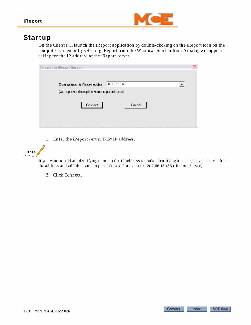
StartupOn the Client PC, launch the iReport application by double-clicking on the iReport icon on the computer screen or by selecting iReport from the Windows Start button. A dialog will appear asking for the IP address of the iReport server.
1. Enter the iReport server TCP/IP address.
Note
If you want to add an identifying name to the IP address to make identifying it easier, leave a space after the address and add the name in parentheses. For example, 207.66.15.185 (iReport Server)
2. Click Connect.
1-18 Manual # 42-02-S026
• Opening iReport• File Menu• Reports Menu• Help Menu
Reference
2
ReferenceThis section describes using iReport:
• Opening iReport
• File Menu
• Reports Menu
• Help Menu
2-1
Reference
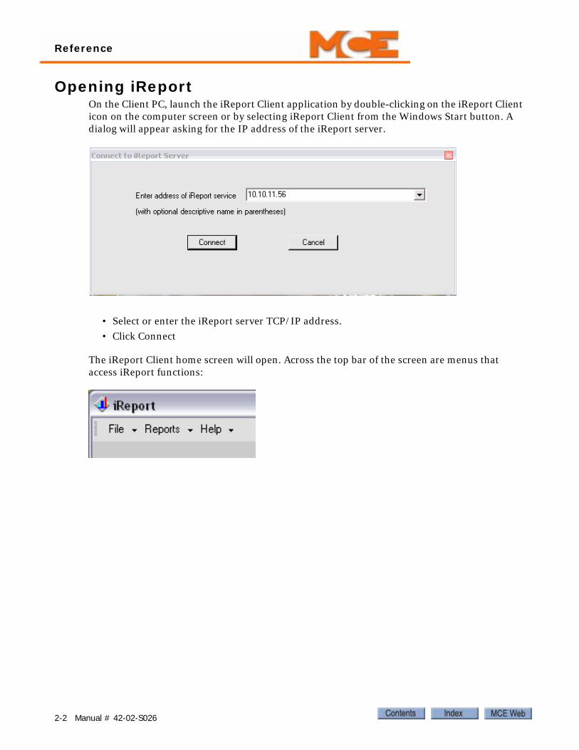
Opening iReportOn the Client PC, launch the iReport Client application by double-clicking on the iReport Client icon on the computer screen or by selecting iReport Client from the Windows Start button. A dialog will appear asking for the IP address of the iReport server.
• Select or enter the iReport server TCP/IP address.
• Click Connect
The iReport Client home screen will open. Across the top bar of the screen are menus that access iReport functions:
2-2 Manual # 42-02-S026

File Menu
2
File Menu• Connect/Disconnect from iReport server.
• Edit dispatchers: Allows you to edit/add/remove the names and IP addresses of dispatchers accessible by this iReport server.
2-3
Reference
Edit Dispatchers
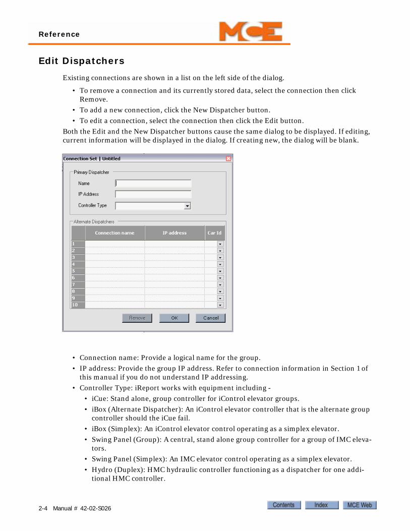
Existing connections are shown in a list on the left side of the dialog.
• To remove a connection and its currently stored data, select the connection then click Remove.
• To add a new connection, click the New Dispatcher button.
• To edit a connection, select the connection then click the Edit button.
Both the Edit and the New Dispatcher buttons cause the same dialog to be displayed. If editing, current information will be displayed in the dialog. If creating new, the dialog will be blank.
• Connection name: Provide a logical name for the group.
• IP address: Provide the group IP address. Refer to connection information in Section 1 of this manual if you do not understand IP addressing.
• Controller Type: iReport works with equipment including -
• iCue: Stand alone, group controller for iControl elevator groups.
• iBox (Alternate Dispatcher): An iControl elevator controller that is the alternate group controller should the iCue fail.
• iBox (Simplex): An iControl elevator control operating as a simplex elevator.
• Swing Panel (Group): A central, stand alone group controller for a group of IMC eleva-tors.
• Swing Panel (Simplex): An IMC elevator control operating as a simplex elevator.
• Hydro (Duplex): HMC hydraulic controller functioning as a dispatcher for one addi-tional HMC controller.
2-4 Manual # 42-02-S026

File Menu
2
• Hydro (Simplex): HMC hydraulic controller operating as a simplex elevator.
• Traction (Duplex): Motion 4000 traction controller functioning as a dispatcher for one additional Motion 4000 controller.
• Traction (Simplex): Motion 4000 traction controller operating as a simplex elevator.
• EC1: Motion 3000ES escalator controller.
• M2000 (Simplex): Motion 2000 hydraulic controller operating as a simplex elevator.
Device ID in the lower pane is assigned automatically by iReport when you save information entered on the Connections screen.
Important Edit Connection InformationiReport stores collected data from defined connections. Because stored data is associated with a connection, you CANNOT edit an existing connection to create a new connection. Instead, cre-ate a completely new connection.
Alternate ConnectionsAlternate connections are connections to be activated if the primary connection fails. Alternate connections must match the iView, System Configuration, Building screen assignments for pri-ority (list position), IP address, and device ID.
Print and Import/Export • Print Preview/Print: Preview and print current screen.
• Import: Used to browse to and import XML files of earlier iReport logs that have been stored on the PC hard drive. Importing a log will overwrite all information in the current log so, before importing, export the current log information to its own XML file.
• Export: Use to export the current log information to an XML file for archival. The export dialog is shown below. The import dialog is similar.
2-5

Reference
NotificationNotification is used to set up information so that the appropriate people are notified by iReport if specific events occur.
A list of persons to be notified appears in the left pane. The right pane shows the SMTP E-mail server for your system. When setting up notification, you will have to provide both E-mail addresses for persons to be notified and the SMTP server information for your E-mail system.
Note
The SMTP server must be configured to allow access. Contact your system administrator or Internet Ser-vice Provider for assistance.
2-6 Manual # 42-02-S026
File Menu
2
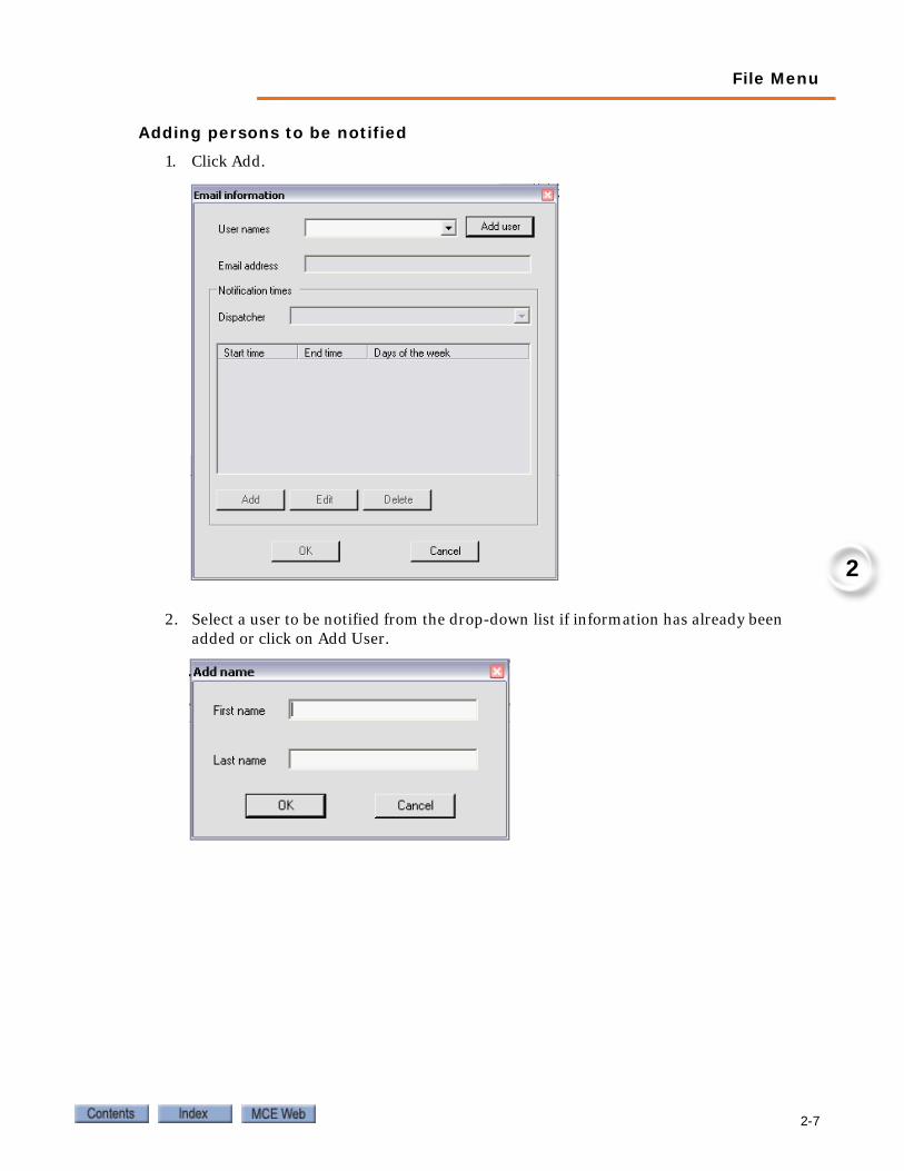
Adding persons to be notified
1. Click Add.
2. Select a user to be notified from the drop-down list if information has already been added or click on Add User.
2-7
Reference
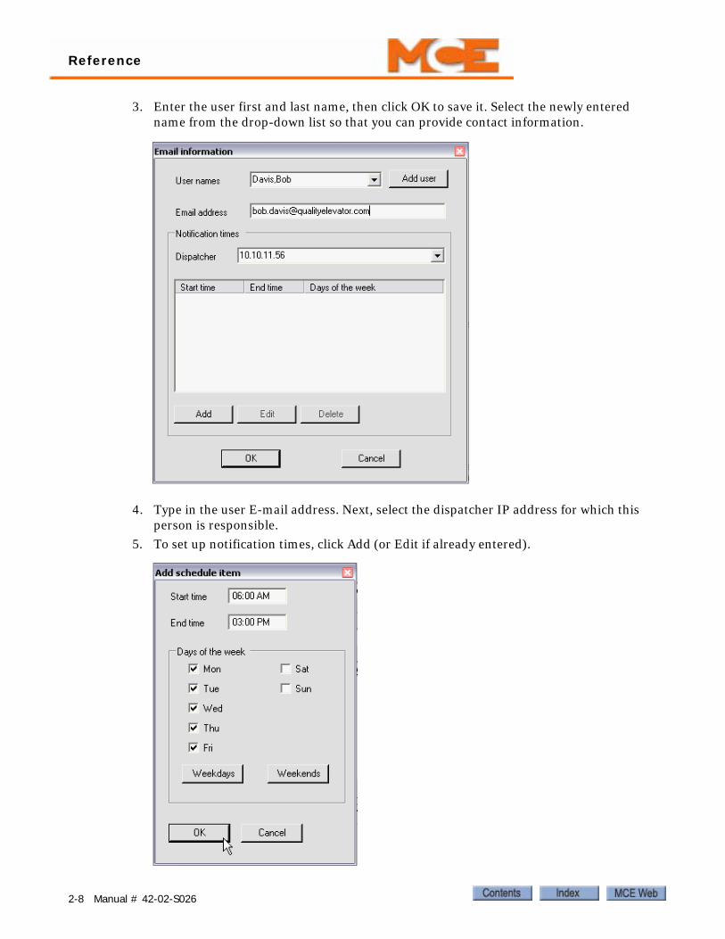
3. Enter the user first and last name, then click OK to save it. Select the newly entered name from the drop-down list so that you can provide contact information.
4. Type in the user E-mail address. Next, select the dispatcher IP address for which this person is responsible.
5. To set up notification times, click Add (or Edit if already entered).
2-8 Manual # 42-02-S026
File Menu
2
6. Enter the times between which this person should be notified.
7. Select specific days or use the Weekdays or Weekends buttons.
8. Click OK.
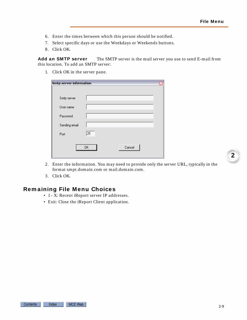
Add an SMTP server The SMTP server is the mail server you use to send E-mail from this location. To add an SMTP server:
1. Click OK in the server pane.
2. Enter the information. You may need to provide only the server URL, typically in the format smpt.domain.com or mail.domain.com.
3. Click OK.
Remaining File Menu Choices• 1 - X: Recent iReport server IP addresses.
• Exit: Close the iReport Client application.
2-9

Reference
Reports MenuUse the Reports menu to access desired reports. The bulleted report synopsis immediately below may seem confusing until you understand the reports. We suggest you skim the synopsis, then experiment with an actual report for better understanding.
• Hall Call Performance: For the selected dispatcher and period of time, on a per riser, per hour basis, graphically displays the number of up and down hall calls placed and, immedi-ately below, the average wait time before those calls were answered. Please refer to “Hall Call Performance” on page 2-12.
• Hall Call Analysis: For the selected dispatcher and period of time, allows you to set up and display on a number per floor and total number basis, clusters of up and down hall calls such that you can see how many calls for each floor were answered in x to xx seconds, how many in xx+1 to xx seconds, etc. You select the cluster increments in seconds and a display maximum time in seconds (for example, ten second increments to a maximum of 60 sec-onds would display six clusters of successive ten second increments and a final cluster of 61+ seconds). Please refer to “Hall Call Analysis” on page 2-13.
• Traffic Analysis: For the selected dispatcher and period of time, allows you to set up and display on a per time of day and total number basis, clusters of up and down hall calls such that you can see how many calls placed during a particular period during the day were answered in x to xx seconds, how many in xx+1 to xx seconds, etc. You select the cluster increments in seconds and a display maximum time in seconds (for example, ten second increments to a maximum of 60 seconds would display six clusters of successive ten sec-ond increments and a final cluster of 61+ seconds). The granularity of the time display is selectable. For example, you can choose thirty-minute slot intervals for 7:30, 8:00, 8:30, etc., or 15-minute slot intervals for 7:30, 7:45, 8:00, etc. Please refer to “Traffic Analysis” on page 2-14.
2-10 Manual # 42-02-S026
Reports Menu
2
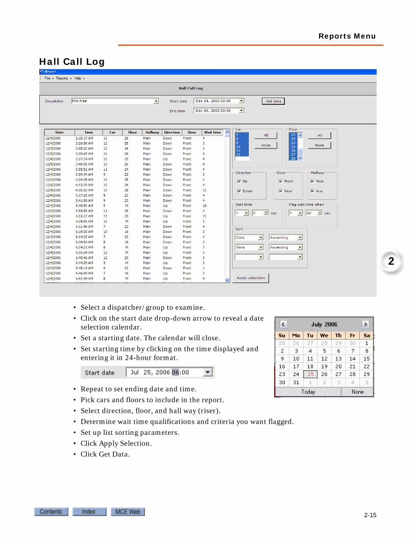
• Hall Call Log: For the selected dispatcher and period of time, allows you to set up and dis-play on a date and time stamp basis, for all selected cars, floors, directions, doors, risers, wait times for each call placed, floor on which it was placed, responding car, direction of travel, doors involved, riser used, and wait time in seconds. You may sort, in ascending or descending order, by any of three sets of conditions, and flag in red any wait times falling outside a mathematically qualified formula. Please refer to “Hall Call Log” on page 2-15.
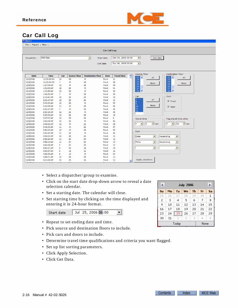
• Car Call Log: For the selected dispatcher and period of time, allows you to set up and dis-play on a date and time stamp basis, for all selected cars, source and destination floors, and front or rear car operating panel, travel times for each car call placed, floor on which it was placed, and destination floor. You may sort, in ascending or descending order, by any of three sets of conditions, and flag in red any travel times falling outside a mathematically qualified formula. Please refer to “Car Call Log” on page 2-16
• Security Call Log: For the selected dispatcher and period of time, allows you to set up and display on a date and time stamp basis, for all selected cars, source and destination floors, and front or rear car operating panel, travel times for each secured car call placed, floor on which it was placed, and destination floor. You may sort, in ascending or descending order, by any of three sets of conditions. Please refer to “Security Call Log” on page 2-17.
• Event Log: For the selected dispatcher and period of time, allows you to display date, time, description, car, and floor for all system events you select. Please refer to “Event Log” on page 2-18.
• Emergency Log: For the selected dispatcher and period of time, allows you to display date, time, description, acknowledgement, and acknowledgement comments for all system emergencies you select. You may sort by car, acknowledgement status, and any or all of three sets of conditions. After displaying, you may highlight and acknowledge or unac-knowledge listed emergencies. Please refer to “Emergency Log” on page 2-19.
• Maintenance Log: For the selected dispatcher and period of time, you may display mainte-nance reports logged by any valid system user. To use this function, you first enter the user’s name to make it valid. When the user or a proxy wishes to enter a maintenance report, they may do so. Please refer to “Maintenance Log” on page 2-20.
• Percent in Service: For the selected dispatcher and period of time, allows you to display all cars for a selected group along with the percentage of time they were in service during that period of time. Please refer to “Percent in Service” on page 2-21.
Note
Supported Events: iReport emergency and events reporting screens provide a complete listing of iControl events. iControl operating software release, December 05, provides notification to iReport for a subset of these events. iReport online help provides a list of December 05 supported events.
2-11

Reference
Hall Call Performance
• Select a dispatcher/group to examine.
• Click on the start date drop-down arrow to reveal a date selection calendar.
• Set a starting date. The calendar will close.
• Set starting time by clicking on the time displayed and entering it in 24-hour format.
• Repeat to set ending date and time.
• Select the hall call riser for which you want data.
• Click Get Data.
• If desired, you can select colors for the bar graph displays.
2-12 Manual # 42-02-S026

Reports Menu
2
Hall Call Analysis
• Select a dispatcher/group to examine.
• Click on the start date drop-down arrow to reveal a date selection calendar.
• Set a starting date. The calendar will close.
• Set starting time by clicking on the time displayed and entering it in 24-hour format.
• Repeat to set ending date and time.
• Select a Wait time interval (Increments in which results will be displayed, i.e., 10 seconds, 20 seconds).
• Select a maximum wait time (anything in excess of this will be displayed in the final col-umn).
• Click Get Data.
2-13

Reference
Traffic Analysis
• Select a dispatcher/group to examine.
• Click on the start date drop-down arrow to reveal a date selection calendar.
• Set a starting date. The calendar will close.
• Set starting time by clicking on the time displayed and entering it in 24-hour format.
• Repeat to set ending date and time.
• Select a Wait time interval (Increments in which results will be displayed, i.e., 10 seconds, 20 seconds).
• Select a maximum wait time (anything in excess of this will be displayed in the final col-umn).
• Select a time slot increment (i.e., 30 minute periods, 45 minute periods, etc.).
• Click Get Data.
2-14 Manual # 42-02-S026
Reports Menu
2
Hall Call Log
• Select a dispatcher/group to examine.
• Click on the start date drop-down arrow to reveal a date selection calendar.
• Set a starting date. The calendar will close.
• Set starting time by clicking on the time displayed and entering it in 24-hour format.
• Repeat to set ending date and time.
• Pick cars and floors to include in the report.
• Select direction, floor, and hall way (riser).
• Determine wait time qualifications and criteria you want flagged.
• Set up list sorting parameters.
• Click Apply Selection.
• Click Get Data.
2-15
Reference
Car Call Log
• Select a dispatcher/group to examine.
• Click on the start date drop-down arrow to reveal a date selection calendar.
• Set a starting date. The calendar will close.
• Set starting time by clicking on the time displayed and entering it in 24-hour format.
• Repeat to set ending date and time.
• Pick source and destination floors to include.
• Pick cars and doors to include.
• Determine travel time qualifications and criteria you want flagged.
• Set up list sorting parameters.
• Click Apply Selection.
• Click Get Data.
2-16 Manual # 42-02-S026

Reports Menu
2
Security Call Log
• Select a dispatcher/group to examine.
• Click on the start date drop-down arrow to reveal a date selection calendar.
• Set a starting date. The calendar will close.
• Set starting time by clicking on the time displayed and entering it in 24-hour format.
• Repeat to set ending date and time.
• Pick source and destination floors to include.
• Pick cars and doors to include.
• Set up list sorting parameters.
• Click Apply Selection.
• Click Get Data.
2-17

Reference
Event Log
• Select a dispatcher/group to examine.
• Click on the start date drop-down arrow to reveal a date selection calendar.
• Set a starting date. The calendar will close.
• Set starting time by clicking on the time displayed and entering it in 24-hour format.
• Repeat to set ending date and time.
• Select events to display.
• Click Apply Selection.
• Click Get Data.
2-18 Manual # 42-02-S026

Reports Menu
2
Emergency Log
• Select a dispatcher/group to examine.
• Click on the start date drop-down arrow to reveal a date selection calendar.
• Set a starting date. The calendar will close.
• Set starting time by clicking on the time displayed and entering it in 24-hour format.
• Repeat to set ending date and time.
• Select emergencies to display.
• Select related criteria.
• Click Apply Selection.
• Click Get Data.
• If desired, highlight and acknowledge/unacknowledge emergencies.
2-19

Reference
Maintenance Log
• Click on the start date drop-down arrow to reveal a date selection calendar.
• Set a starting date. The calendar will close.
• Set starting time by clicking on the time displayed and entering it in 24-hour format.
• Repeat to set ending date and time.
• Click Get Data to display entries.
Management/Entries Users and entries may be added or deleted:
• To add a user, click Add Entry, provide the name, click Add Name.
• To delete a user, click Delete User, select the name, click Delete, then Close.
• To add an entry, click Add Entry, pick the User, key in the event, click OK.
• To delete an entry, highlight it, then click Delete Entry.
2-20 Manual # 42-02-S026

Help Menu
2
Percent in Service
• Select a dispatcher/group to examine.
• Click on the start date drop-down arrow to reveal a date selection calendar.
• Set a starting date. The calendar will close.
• Set starting time by clicking on the time displayed and entering it in 24-hour format.
• Repeat to set ending date and time.
• Click Get Data.
Help Menu• iReport Help: Opens help.
• About iReport: Displays software version information.
2-21

Index
CCar Call Log, definition 2-11Car Call Log, usage 2-16, 2-17CAT 5 cable 1-8Client PC 1-3Controllers initiate communication 1-3DDevice ID 2-5DSL 1-2
EEC1 2-5Emergency Log, definition 2-11Emergency Log, usage 2-19Ethernet 1-1, 1-5Ethernet cable length 1-8Ethernet cable provided 1-4Event Log, definition 2-11Event Log, usage 2-18Export 2-5Export data to a file 1-3
FFactory-default TCP/IP 1-5Firewall software 1-4
GGateway 1-5Group dispatchers, constant connection 1-3
HHall Call Analysis, definition 2-10Hall Call Analysis, usage 2-13Hall Call Log, definition 2-11Hall Call Log, usage 2-15Hall Call Performance, definition 2-10Hall Call Performance, usage 2-12Hardware Type 2-4Hydro (Duplex) 2-4Hydro (Simplex) 2-5
IiBox (Alternate Dispatcher) 2-4iBox (Simplex) 2-4iCue 2-4Import 2-5Import an archived file 1-3IP addresses 1-8, 2-4iReport data storage 1-3iReport server TCP/IP address 2-2
LLAN 1-5
MM2000 (Simplex 2-5Maintenance Log, definition 2-11Maintenance Log, usage 2-20
NNetwork connection extension 1-4Notification 2-6
PPercent in Service, definition 2-11Percent in Service, usage 2-21Print Preview/Print 2-5
SSecurity Call Log 2-11, 2-17SMTP E-mail server 2-6SMTP server 2-9Subnet Mask 1-5Swing Panel (Simplex) 2-4
TTCP/IP 1-5Traction (Duplex) 2-5Traction (Simplex) 2-5Traffic Analysis, definition 2-10Traffic Analysis, usage 2-14
XXML format 1-3
Index-1
