user guide, motion 3000es escalator control 3000es escalator control 2 manual # 42-02-e001 the...
TRANSCRIPT

Motion Control Engineering, Inc.11380 White Rock RoadRancho Cordova, CA 95742
voice 916 463 9200fax 916 463 9201www.mceinc.com
User Guide,Motion 3000ES Escalator Control
Manual # 42-02-E001, Rev B6, February 2014

CopyrightCopyright 2014, Motion Control Engineering. All Rights Reserved.This document may not be reproduced, electronically or mechanically, in whole or in part, without written permission from Motion Control Engineering.
TrademarksAll trademarks or registered product names appearing in this document are the exclusive property of the respective owners.
Warning and DisclaimerAlthough every effort has been made to make this document as complete and accurate as possible, Motion Control Engineering and the document authors, publishers, distributors, and representatives have neither liability nor responsibility for any loss or damage arising from information contained in this document or from informational errors or omissions. Information contained in this document shall not be deemed to constitute a commitment to provide service, equipment, or software by Motion Control Engineering or the document authors, publishers, distributors, or representatives.
Limited WarrantyMotion Control Engineering (manufacturer) warrants its products for a period of 15 months from the date of shipment from its factory to be free from defects in workmanship and materials. Any defect appearing more than 15 months from the date of shipment from the factory shall be deemed to be due to ordinary wear and tear. Manufacturer, however, assumes no risk or liability for results of the use of the products purchased from it, including, but without limiting the generality of the forgoing: (1) The use in combination with any electrical or electronic components, circuits, systems, assemblies or any other material or equipment (2) Unsuitability of this product for use in any circuit, assembly or environment. Purchasers’ rights under this warranty shall consist solely of requiring the manufacturer to repair, or in manufacturer's sole discretion, replace free of charge, F.O.B. factory, any defective items received at said factory within the said 15 months and determined by manufacturer to be defective. The giving of or failure to give any advice or recommendation by manufacturer shall not constitute any warranty by or impose any liability upon the manufacturer. This warranty constitutes the sole and exclusive remedy of the purchaser and the exclusive liability of the manufacturer, AND IN LIEU OF ANY AND ALL OTHER WARRANTIES, EXPRESSED, IMPLIED, OR STATUTORY AS TO MERCHANTABILITY, FITNESS, FOR PURPOSE SOLD, DESCRIPTION, QUALITY PRODUCTIVENESS OR ANY OTHER MATTER. In no event will the manufacturer be liable for special or consequential damages or for delay in performance of this warranty.
Products that are not manufactured by MCE (such as drives, CRT's, modems, printers, etc.) are not covered under the above warranty terms. MCE, however, extends the same warranty terms that the original manufacturer of such equipment provide with their product (refer to the warranty terms for such products in their respective manual).

Important Precautions and Useful InformationThis preface contains information that will help you understand and safely maintain MCE equipment. We strongly recommend you review this preface and read this manual before installing, adjusting, or maintaining Motion Control Engineering equipment. This preface dis-cusses:
• Safety and Other Symbol Meanings
• Environmental Considerations
• In This Guide
Safety and Other Symbol Meanings
DangerThis manual symbol is used to alert you to procedures, instructions, or situations which, if not done properly, might result in personal injury or substantial equipment damage.
CautionThis manual symbol is used to alert you to procedures, instructions, or situations which, if not done properly, might result in equipment damage.
Note
This manual symbol is used to alert you to instructions or other immediately helpful information.
Environmental Considerations• Keep ambient temperature between 32 and 104 degrees F (0 to 40 degrees C).
• Prevent condensation on the equipment.
• Make certain that power line fluctuations are within plus or minus 5% of proper value.
In This Guide:This guide is the installation, adjustment, and troubleshooting guide for the Motion 3000ES escalator control. When viewed online as a pdf file, hyperlinks link to related topics and infor-mational websites. The manual includes:
• Contents: Table of Contents. When viewed online as a pdf file, hyperlinks in the Contents link to the associated topic in the body of the manual.
• Motion 3000ES: Product Description, installation, and troubleshooting instructions.

Motion 3000ES ContentsAbout Motion 3000ES . . . . . . . . . . . . . . . . . . . . . . . . . . . . . . . . . . . . . . . . . . . . . . . . .1
Installation . . . . . . . . . . . . . . . . . . . . . . . . . . . . . . . . . . . . . . . . . . . . . . . . . . . . . . . . . 3Equipment Grounding . . . . . . . . . . . . . . . . . . . . . . . . . . . . . . . . . . . . . . . . . . . . . . . . . . . . . . . . . 3
Check for Shorts to Ground . . . . . . . . . . . . . . . . . . . . . . . . . . . . . . . . . . . . . . . . . . . . . . . . . . 3AC Voltage Verification and Wiring . . . . . . . . . . . . . . . . . . . . . . . . . . . . . . . . . . . . . . . . . . . . . . 4
Verifying Main Line Power and Wiring the Controller . . . . . . . . . . . . . . . . . . . . . . . . . . . . 4Initial Power Up . . . . . . . . . . . . . . . . . . . . . . . . . . . . . . . . . . . . . . . . . . . . . . . . . . . . . . . . . . . . . . 5
Controller Parameters . . . . . . . . . . . . . . . . . . . . . . . . . . . . . . . . . . . . . . . . . . . . . . . . . . . . . . . 6Drive Parameters . . . . . . . . . . . . . . . . . . . . . . . . . . . . . . . . . . . . . . . . . . . . . . . . . . . . . . . . . . . 8Operation Description when Equipped with a Drive. . . . . . . . . . . . . . . . . . . . . . . . . . . . . . 8
Normal Mode (Single Speed): . . . . . . . . . . . . . . . . . . . . . . . . . . . . . . . . . . . . . . . . . . . . . 8Energy Saving Modes (when code allows speed change during operation) . . . . . . . . 8Energy Saving Mode (Two Speeds, Starting Direction Only) . . . . . . . . . . . . . . . . . . . . 8Intelligent Mode (Two Speeds, Two Directions Based on Entry Detection) . . . . . . . . 8CT Emerson . . . . . . . . . . . . . . . . . . . . . . . . . . . . . . . . . . . . . . . . . . . . . . . . . . . . . . . . . . . . 9CT Menu Access . . . . . . . . . . . . . . . . . . . . . . . . . . . . . . . . . . . . . . . . . . . . . . . . . . . . . . . . . 9CT Parameter Entry . . . . . . . . . . . . . . . . . . . . . . . . . . . . . . . . . . . . . . . . . . . . . . . . . . . . . 10CT Saving Parameters . . . . . . . . . . . . . . . . . . . . . . . . . . . . . . . . . . . . . . . . . . . . . . . . . . . 10CT Parameter Check . . . . . . . . . . . . . . . . . . . . . . . . . . . . . . . . . . . . . . . . . . . . . . . . . . . . 10KEB F5 . . . . . . . . . . . . . . . . . . . . . . . . . . . . . . . . . . . . . . . . . . . . . . . . . . . . . . . . . . . . . . . 11
Field Connections . . . . . . . . . . . . . . . . . . . . . . . . . . . . . . . . . . . . . . . . . . . . . . . . . . . . . . . . . . . 14Checking the Motor . . . . . . . . . . . . . . . . . . . . . . . . . . . . . . . . . . . . . . . . . . . . . . . . . . . . . . . . 14Wiring the Motor to the Controller . . . . . . . . . . . . . . . . . . . . . . . . . . . . . . . . . . . . . . . . . . . 14Brake Resistance; DC Brake Only . . . . . . . . . . . . . . . . . . . . . . . . . . . . . . . . . . . . . . . . . . . . 15Wiring the Brake . . . . . . . . . . . . . . . . . . . . . . . . . . . . . . . . . . . . . . . . . . . . . . . . . . . . . . . . . . 15Safety String . . . . . . . . . . . . . . . . . . . . . . . . . . . . . . . . . . . . . . . . . . . . . . . . . . . . . . . . . . . . . . 15Auxiliary Brake Information. . . . . . . . . . . . . . . . . . . . . . . . . . . . . . . . . . . . . . . . . . . . . . . . . 15Proximity Sensors / Rail and Step Speed . . . . . . . . . . . . . . . . . . . . . . . . . . . . . . . . . . . . . . 16
Step Sensors . . . . . . . . . . . . . . . . . . . . . . . . . . . . . . . . . . . . . . . . . . . . . . . . . . . . . . . . . . . 16Rail Speed Sensors . . . . . . . . . . . . . . . . . . . . . . . . . . . . . . . . . . . . . . . . . . . . . . . . . . . . . . 18Display Board Connections . . . . . . . . . . . . . . . . . . . . . . . . . . . . . . . . . . . . . . . . . . . . . . 21
Initial System Startup . . . . . . . . . . . . . . . . . . . . . . . . . . . . . . . . . . . . . . . . . . . . . . . 24Prestart Check . . . . . . . . . . . . . . . . . . . . . . . . . . . . . . . . . . . . . . . . . . . . . . . . . . . . . . . . . . . . . . 24
Construction Mode . . . . . . . . . . . . . . . . . . . . . . . . . . . . . . . . . . . . . . . . . . . . . . . . . . . . . . . 24Initial Startup . . . . . . . . . . . . . . . . . . . . . . . . . . . . . . . . . . . . . . . . . . . . . . . . . . . . . . . . . . . . . . . 25
Power Up . . . . . . . . . . . . . . . . . . . . . . . . . . . . . . . . . . . . . . . . . . . . . . . . . . . . . . . . . . . . . . . . 25Inspection Operation. . . . . . . . . . . . . . . . . . . . . . . . . . . . . . . . . . . . . . . . . . . . . . . . . . . . . . . 25
Remote Inspection Control Connection . . . . . . . . . . . . . . . . . . . . . . . . . . . . . . . . . . . . 26Brake Pick and Drop . . . . . . . . . . . . . . . . . . . . . . . . . . . . . . . . . . . . . . . . . . . . . . . . . . . . 26Escalator Braking Distance Feature . . . . . . . . . . . . . . . . . . . . . . . . . . . . . . . . . . . . . . . 27Escalator Learn Operation . . . . . . . . . . . . . . . . . . . . . . . . . . . . . . . . . . . . . . . . . . . . . . . 28Safety String Check . . . . . . . . . . . . . . . . . . . . . . . . . . . . . . . . . . . . . . . . . . . . . . . . . . . . . 28
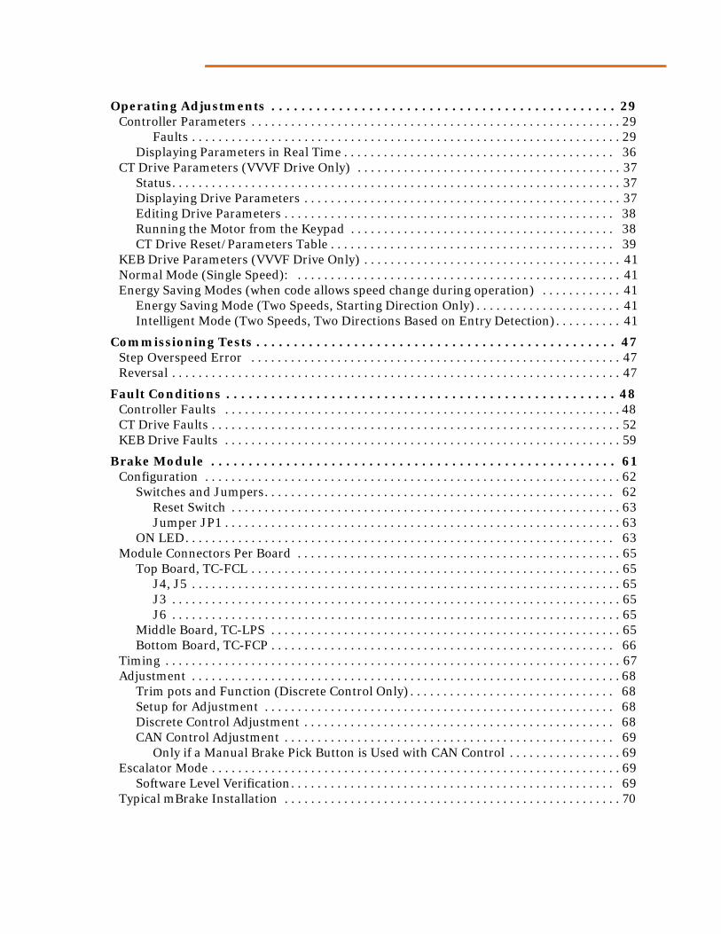
Operating Adjustments . . . . . . . . . . . . . . . . . . . . . . . . . . . . . . . . . . . . . . . . . . . . . . 29Controller Parameters . . . . . . . . . . . . . . . . . . . . . . . . . . . . . . . . . . . . . . . . . . . . . . . . . . . . . . . . 29
Faults . . . . . . . . . . . . . . . . . . . . . . . . . . . . . . . . . . . . . . . . . . . . . . . . . . . . . . . . . . . . . . . . . 29Displaying Parameters in Real Time . . . . . . . . . . . . . . . . . . . . . . . . . . . . . . . . . . . . . . . . . 36
CT Drive Parameters (VVVF Drive Only) . . . . . . . . . . . . . . . . . . . . . . . . . . . . . . . . . . . . . . . . 37Status. . . . . . . . . . . . . . . . . . . . . . . . . . . . . . . . . . . . . . . . . . . . . . . . . . . . . . . . . . . . . . . . . . . . 37Displaying Drive Parameters . . . . . . . . . . . . . . . . . . . . . . . . . . . . . . . . . . . . . . . . . . . . . . . . 37Editing Drive Parameters . . . . . . . . . . . . . . . . . . . . . . . . . . . . . . . . . . . . . . . . . . . . . . . . . . 38Running the Motor from the Keypad . . . . . . . . . . . . . . . . . . . . . . . . . . . . . . . . . . . . . . . . 38CT Drive Reset/Parameters Table . . . . . . . . . . . . . . . . . . . . . . . . . . . . . . . . . . . . . . . . . . . 39
KEB Drive Parameters (VVVF Drive Only) . . . . . . . . . . . . . . . . . . . . . . . . . . . . . . . . . . . . . . . 41Normal Mode (Single Speed): . . . . . . . . . . . . . . . . . . . . . . . . . . . . . . . . . . . . . . . . . . . . . . . . . 41Energy Saving Modes (when code allows speed change during operation) . . . . . . . . . . . . 41
Energy Saving Mode (Two Speeds, Starting Direction Only) . . . . . . . . . . . . . . . . . . . . . . 41Intelligent Mode (Two Speeds, Two Directions Based on Entry Detection). . . . . . . . . . 41
Commissioning Tests . . . . . . . . . . . . . . . . . . . . . . . . . . . . . . . . . . . . . . . . . . . . . . . . 47Step Overspeed Error . . . . . . . . . . . . . . . . . . . . . . . . . . . . . . . . . . . . . . . . . . . . . . . . . . . . . . . . 47Reversal . . . . . . . . . . . . . . . . . . . . . . . . . . . . . . . . . . . . . . . . . . . . . . . . . . . . . . . . . . . . . . . . . . . . 47
Fault Conditions . . . . . . . . . . . . . . . . . . . . . . . . . . . . . . . . . . . . . . . . . . . . . . . . . . . . 48Controller Faults . . . . . . . . . . . . . . . . . . . . . . . . . . . . . . . . . . . . . . . . . . . . . . . . . . . . . . . . . . . . 48CT Drive Faults . . . . . . . . . . . . . . . . . . . . . . . . . . . . . . . . . . . . . . . . . . . . . . . . . . . . . . . . . . . . . . 52KEB Drive Faults . . . . . . . . . . . . . . . . . . . . . . . . . . . . . . . . . . . . . . . . . . . . . . . . . . . . . . . . . . . . 59
Brake Module . . . . . . . . . . . . . . . . . . . . . . . . . . . . . . . . . . . . . . . . . . . . . . . . . . . . . . 61Configuration . . . . . . . . . . . . . . . . . . . . . . . . . . . . . . . . . . . . . . . . . . . . . . . . . . . . . . . . . . . . . . . 62
Switches and Jumpers. . . . . . . . . . . . . . . . . . . . . . . . . . . . . . . . . . . . . . . . . . . . . . . . . . . . . 62Reset Switch . . . . . . . . . . . . . . . . . . . . . . . . . . . . . . . . . . . . . . . . . . . . . . . . . . . . . . . . . . . 63Jumper JP1 . . . . . . . . . . . . . . . . . . . . . . . . . . . . . . . . . . . . . . . . . . . . . . . . . . . . . . . . . . . . 63
ON LED. . . . . . . . . . . . . . . . . . . . . . . . . . . . . . . . . . . . . . . . . . . . . . . . . . . . . . . . . . . . . . . . . 63Module Connectors Per Board . . . . . . . . . . . . . . . . . . . . . . . . . . . . . . . . . . . . . . . . . . . . . . . . . 65
Top Board, TC-FCL . . . . . . . . . . . . . . . . . . . . . . . . . . . . . . . . . . . . . . . . . . . . . . . . . . . . . . . . 65J4, J5 . . . . . . . . . . . . . . . . . . . . . . . . . . . . . . . . . . . . . . . . . . . . . . . . . . . . . . . . . . . . . . . . . 65J3 . . . . . . . . . . . . . . . . . . . . . . . . . . . . . . . . . . . . . . . . . . . . . . . . . . . . . . . . . . . . . . . . . . . . 65J6 . . . . . . . . . . . . . . . . . . . . . . . . . . . . . . . . . . . . . . . . . . . . . . . . . . . . . . . . . . . . . . . . . . . . 65
Middle Board, TC-LPS . . . . . . . . . . . . . . . . . . . . . . . . . . . . . . . . . . . . . . . . . . . . . . . . . . . . . 65Bottom Board, TC-FCP . . . . . . . . . . . . . . . . . . . . . . . . . . . . . . . . . . . . . . . . . . . . . . . . . . . . 66
Timing . . . . . . . . . . . . . . . . . . . . . . . . . . . . . . . . . . . . . . . . . . . . . . . . . . . . . . . . . . . . . . . . . . . . . 67Adjustment . . . . . . . . . . . . . . . . . . . . . . . . . . . . . . . . . . . . . . . . . . . . . . . . . . . . . . . . . . . . . . . . . 68
Trim pots and Function (Discrete Control Only) . . . . . . . . . . . . . . . . . . . . . . . . . . . . . . . 68Setup for Adjustment . . . . . . . . . . . . . . . . . . . . . . . . . . . . . . . . . . . . . . . . . . . . . . . . . . . . . 68Discrete Control Adjustment . . . . . . . . . . . . . . . . . . . . . . . . . . . . . . . . . . . . . . . . . . . . . . . 68CAN Control Adjustment . . . . . . . . . . . . . . . . . . . . . . . . . . . . . . . . . . . . . . . . . . . . . . . . . . 69
Only if a Manual Brake Pick Button is Used with CAN Control . . . . . . . . . . . . . . . . . 69Escalator Mode . . . . . . . . . . . . . . . . . . . . . . . . . . . . . . . . . . . . . . . . . . . . . . . . . . . . . . . . . . . . . . 69
Software Level Verification. . . . . . . . . . . . . . . . . . . . . . . . . . . . . . . . . . . . . . . . . . . . . . . . . 69Typical mBrake Installation . . . . . . . . . . . . . . . . . . . . . . . . . . . . . . . . . . . . . . . . . . . . . . . . . . . 70


• About Motion 3000ES• Installation• Initial System Startup• Operating Adjustments• Fault Conditions
Motion 3000ES Escalator Control
About Motion 3000ESMotion 3000ES is a field programmable escalator control from Motion Control Engineering. Motion 3000ES controls provide hardware flexibility, allowing enclosure size and motor drive, control keypad, and processor board locations (in cabinet or remote) to vary depending on the needs of the installation. Escalator controls are available in VVVF Variable Speed, Across-the-Line, or Wye/Delta Direct Line Control versions.
Motion 3000ES is fully ASME A17.1-2010, CSA B44.10, BS EN 115, and AS 1735.5 compliant, with independent, redundant safety string inputs, signal path, and processing to ensure safe operation. Motion 3000ES controls feature:
• Prominent, externally accessible machine controls
• VVVF drive or Wye/Delta compatibility
• High speed CAN serial bus communication
• High visibility LED message and parameter displays
• Internal event storage with time stamp
• Multiple remote display support
• Direct parameter entry (no external devices required)
• Cabinet or remote mount inspection control sockets
• Field programmable
1
Motion 3000ES Escalator Control
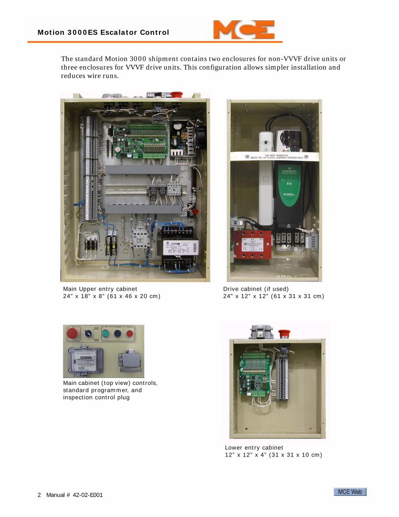
The standard Motion 3000 shipment contains two enclosures for non-VVVF drive units or three enclosures for VVVF drive units. This configuration allows simpler installation and reduces wire runs.
Lower entry cabinet12” x 12” x 4” (31 x 31 x 10 cm)
Main Upper entry cabinet24” x 18” x 8” (61 x 46 x 20 cm)
Drive cabinet (if used)24” x 12” x 12” (61 x 31 x 31 cm)
Main cabinet (top view) controls, standard programmer, and inspection control plug
2 Manual # 42-02-E001

Installation
InstallationThis section contains:
• Equipment grounding
• AC connections
• Initial power up
• Field connections
Equipment GroundingFor good grounding, quality wiring materials and methods must be used. Grounding must con-form to all applicable codes. Proper grounding is essential for system safety and helps to reduce noise-induced problems. General grounding guidelines include:
• The grounding wire to the equipment cabinet should be the same gauge (diameter) or larger than the primary AC power feeders for the controller and should be as short as pos-sible.
• The grounding wire between equipment cabinets may follow a branching or daisy-chain configuration, but the wire must terminate at the last controller and NOT loop back.
• You must provide a direct, solid ground to the controller and motor. An indirect ground, such as the building structure or a water pipe, may not provide proper grounding and could act as an antenna — radiating RFI noise and interfering with electronic equipment in the building.
• The conduit containing the AC power feeders must not be used for grounding.
Check for Shorts to GroundCheck for shorts to ground before powering up the system. Power must be OFF at the main disconnect. If any shorts to ground are discovered, they must be corrected before proceeding. A short to ground is defined as having a resistance of less than 20 ohms between ground and the terminal being tested.
DangerBe certain that power is OFF at the main disconnect before proceeding.
1. Disengage all fuses at the bottom of the cabinet.2. Measure the resistance between the cabinet ground and all field connection terminals
(connectors J1 through J4 and J6 through J9 on the EC-MCB board and J1 through J4 on the EC-SCB board).
3. Check for shorts to ground on motor power terminals L1, L2, and L3.4. Check for shorts to ground on brake terminals B1 and B2, (EB1 and EB2 where applica-
ble).5. If no shorts to ground are discovered, re-engage the fuses. Refer to the job prints for fuse
location if necessary.
3

Motion 3000ES Escalator Control
AC Voltage Verification and WiringThe AC wiring instructions in this section describe wiring from commercial power. The majority of technical information is contained in the MCE job prints package and referenced here as nec-essary. As shown in the job prints (if specified), an isolation transformer may be used to clean up “dirty” commercial power or shift voltage levels, and also prevent noise from electrical equipment from being introduced back into the building power system. Isolation transformers are specified in some, but not all, installations.
AC Voltage Verification and Wiring instructions include:
• Verifying main line power and wiring the controller
• Initial power up
Note
All conductors entering or leaving the controller cabinet must be in conduit. High voltage, high current conductors, such as power conductors from the fused disconnect or isolation trans-former, must be separated from control wires. It is essential that control wires be routed through a separate conduit away from high current conductors.
Incoming power to the controller and outgoing power wires to the motor must be in their respective grounded conduit.
Verifying Main Line Power and Wiring the Controller1. Consult the job prints. Verify that AC supply is as specified.
Note
Proper motor branch circuit protection in the form of a fused disconnect switch or circuit breaker must be provided for each escalator according to applicable electrical code. Each dis-connect or breaker must be clearly labeled with the escalator number. The electrical contractor must determine the wire size for the main AC power supply and for the wiring from the discon-nect or breaker to the escalator controller.
2. If an isolation transformer is used, connect AC supply wiring to the transformer, and transformer outputs to the controller, as shown in the job prints.
3. If no isolation transformer is used, connect AC supply wiring to the controller as shown in the job prints.
4 Manual # 42-02-E001

Installation
Initial Power UpAfter AC power is connected, you are ready to temporarily power up the controller and check initial controller and drive parameters.
CautionThis procedure assumes that no field wiring has been connected to the controller. If field wiring has been connected, disconnect it before beginning this procedure. Before applying power, physically check all components. Components loosened during shipment may cause damage.
1. On the controller, verify:
• Inspection/Auto switch in Inspection position
2. Power up the controller. If the controller fails to power up, refer to the job prints and check supply connections and fuses.
5

Motion 3000ES Escalator Control
Controller ParametersA simple keypad and display allow access to controller parameters.
• ESC button: Press to exit parameter settings without saving changes.
• UP button: Move up in parameter settings list. Change the value of a selected digit. (Digit will be flashing when its value can be changed.)
• DOWN button: Move down in parameter settings list. Move between digits of a selected value.
• OK: Select/Save.
• At the highest level, parameters are grouped under seven functions, FUN1 through FUN7.
• Within each function, parameters are listed numerically by function and parameter order (i.e., F1-01 is the first parameter of function FUN1, F1-02 is the second, etc.).
• Consult the complete parameter table for an ordered list of all parameters. Please refer to “Controller Parameters” on page 30.
• To reset any latched fault, press both UP and DOWN buttons and hold them down for two seconds.
Your controller may have the optional LCD display. The LCD display is capable of displaying full text status and error messages.
6 Manual # 42-02-E001

Installation
Parameter setting example — Setting automatic oiling duration:
• Check the table to see that oiling duration is parameter F2-02.
• Press OK to access parameters.
• Press UP until FUN2 is displayed.
• Press OK to select FUN2 parameters.
• Press UP until F2-02 is displayed.
• Press OK to display the current setting. (For example: 0030 indicates 30 seconds.)
• Press DOWN to move to the digit you want to change (selected digit flashes).
• Press UP to change the digit value. (For example, changing the 3 to a 4.)
• Press OK to save the new value.
• Press ESC to exit the set up menu. (The display will show “STOP.”)
Note
The programming display is also used to display error codes if the controller discovers a prob-lem. Please refer to “Fault Conditions” on page 48.
If an error is displayed, first correct the condition, then press and hold the UP and DOWN but-tons simultaneously — the error will clear after three seconds.
Check the following parameters to verify they match the physical configuration of your system. Set if needed.
• F1-01, Brake contact: N/C or N/O (or disable if the brake is not equipped with a contact)
• F1-02, Auxiliary brake contact: N/C, N/O, Cancel, or Disable.Cancel means that the system does not have an auxiliary brake. The T4 output is always OFF by default, is not connected to anything, and never changes state.
Disable means that the system does have an auxiliary brake but does not have a contact to feedback the brake position to the controller. The system ignores the status of input P22 (Auxiliary Brake Contact) and drops the auxiliary brake (T4 output) in the following instances:
• Overspeed; Reversal; Broken Drive Chain; Loss of Power.
• F4-01, Drive mode:
• 0: VVVF or ATL
• 1: Wye/Delta
• F4-03, EC-SCB presence: Yes
Note
Construction Mode: Parameter F5-07, when set to a value of 1 (one), places the escalator in a mode where all faults are automatically reset (no fault is latched). This mode is useful during installation. While in this mode, the escalator control WILL NOT enter automatic operation. Before automatic operation may be entered, F5-07 must be set to 0 (zero). When set to 0, fault latching will return to normal.
7
Motion 3000ES Escalator Control
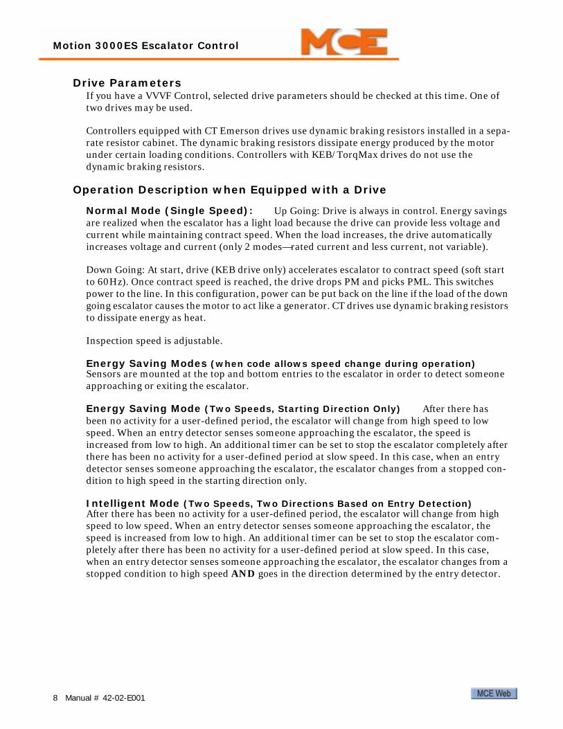
Drive ParametersIf you have a VVVF Control, selected drive parameters should be checked at this time. One of two drives may be used.
Controllers equipped with CT Emerson drives use dynamic braking resistors installed in a sepa-rate resistor cabinet. The dynamic braking resistors dissipate energy produced by the motor under certain loading conditions. Controllers with KEB/TorqMax drives do not use the dynamic braking resistors.
Operation Description when Equipped with a Drive
Normal Mode (Single Speed): Up Going: Drive is always in control. Energy savings are realized when the escalator has a light load because the drive can provide less voltage and current while maintaining contract speed. When the load increases, the drive automatically increases voltage and current (only 2 modes—rated current and less current, not variable).
Down Going: At start, drive (KEB drive only) accelerates escalator to contract speed (soft start to 60Hz). Once contract speed is reached, the drive drops PM and picks PML. This switches power to the line. In this configuration, power can be put back on the line if the load of the down going escalator causes the motor to act like a generator. CT drives use dynamic braking resistors to dissipate energy as heat.
Inspection speed is adjustable.
Energy Saving Modes (when code allows speed change during operation) Sensors are mounted at the top and bottom entries to the escalator in order to detect someone approaching or exiting the escalator.
Energy Saving Mode (Two Speeds, Starting Direction Only) After there has been no activity for a user-defined period, the escalator will change from high speed to low speed. When an entry detector senses someone approaching the escalator, the speed is increased from low to high. An additional timer can be set to stop the escalator completely after there has been no activity for a user-defined period at slow speed. In this case, when an entry detector senses someone approaching the escalator, the escalator changes from a stopped con-dition to high speed in the starting direction only.
Intelligent Mode (Two Speeds, Two Directions Based on Entry Detection) After there has been no activity for a user-defined period, the escalator will change from high speed to low speed. When an entry detector senses someone approaching the escalator, the speed is increased from low to high. An additional timer can be set to stop the escalator com-pletely after there has been no activity for a user-defined period at slow speed. In this case, when an entry detector senses someone approaching the escalator, the escalator changes from a stopped condition to high speed AND goes in the direction determined by the entry detector.
8 Manual # 42-02-E001

Installation
CT Emerson The drive uses a direct entry, LED display and keypad. The display is a two-row display with the upper row showing drive status or the current menu and parameter num-ber being viewed. The lower row shows the value of the displayed parameter number or, if the drive has tripped, the specific fault indication. Read the manual shipped with the drive for details not provided here. (Please refer to “CT Drive Fault Displays” on page 52 for a listing of drive faults.)
CT Menu Access CT drive parameters beyond menu 0 may be protected by User Secu-rity and Parameter Access Level settings. Parameter Access Level determines whether the user can access menus beyond menu 0. User Security determines whether the user can change parameters or just read them.
To set User Security:
1. At parameter 0.34, enter the desired security code (from 1 to 999), then press the M but-ton.
2. Set parameter 0.49, Access Level, to “2” (Local).
3. Press the drive reset button to activate the security code and reset the drive. The drive will return to access Level 1 (Menu 0 only) and the security code entry will be hidden (0.34).
To set Access Level so advanced menus can be accessed:
1. Set parameter 0.49, Access Level, to “1” (Level 2).2. Select a parameter to edit and press the M button. The drive will display CodE.
3. Use the arrow buttons to set the security code, then press the M button. The drive will display the parameter to be set in edit mode.
4. To lock User Security again, set parameter 0.49 to “2” (Local) and press the reset button.
To disable User Security (so it does not have to be used each time):
1. At parameter 0.34, enter the security code, then press the M button.2. Set parameter 0.49, Access Level, to “2” (Local).3. Press the drive reset button to unlock the security code and reset the drive.4. Set parameter 0.34 to “0” then press the M button. User Security is now disabled.
9

Motion 3000ES Escalator Control
CT Parameter Entry The graphic below provides the parameter editing sequence.
CT Saving Parameters Once you have set parameters as desired, you must do the fol-lowing to save them:
1. Enter 1000 in parameter 0.00. (If the drive is in under voltage trip state or being sup-plied from a 48V backup source, 1001 must be entered instead.)
2. Press the drive reset button.
CT Parameter Check Check the following parameters now. Please refer to “CT Drive Parameters” on page 39. Set if needed.
• Motor rated frequency, Hz (0.47)• Motor rated current, A (0.46)• Motor rated speed, RPM (0.45)• Motor rated voltage, V (0.44)• Maximum frequency, Hz (0.02)• Acceleration rate, s/100Hz (0.03)• Deceleration rate, s/100Hz (0.04)• Ramp Mode Select = FAST (0.15)
At this point, shut down the controller before making field connections.
M
Status mode,display not flashing
Press or
MPress to enter edit mode
Parameter mode,upper display flashing
Use to selectparameterto edit
Use to select another parameter to edit
Use to changevalue
MPress to exit edit mode when ready
MPress to return to status mode
Edit mode,character to edit in lower line flashing
OR
10 Manual # 42-02-E001

Installation
KEB F5 The KEB F5 drive uses an LED display and a membrane keypad. Parameters are displayed and changed as shown below.
The blinking point determinesthe active (changeable) part ofthe parameter
Display Parameter Group
Display Parameter Number
ENTERF/R START
STOP
FUNC.SPEED
ENTERF/R
START
STOP
FUNC.SPEED
ENTERF/R
change between parameter group and
parameter number
With the keys
select the respectiveparameter number
1,2,3,4...99
With the keys
select theparameter group“US”, “LF”, “LP”, “Ld”,
“ru”, “do”
START
STOP
FUNC.SPEED
START
STOP
FUNC.SPEED
ENTERF/R
START
STOP
FUNC.SPEED
ENTERF/R
Display Parameter Display Parameter Value
Increase/Decrease Parameter Value
Parameter Display
Parameter Selection
Parameter Change
Changes are accepted and saved only after ENTER is pressed.Some parameters (i.e., motor data) cannot be changed while the escalator is operating.
11

Installation
At this point, shut down the controller before making field connections.
13

Motion 3000ES Escalator Control
Field ConnectionsThis section contains:
• Motor connections
• Brake connections
• Safety and I/O connections
Checking the MotorIf this job reuses existing rotating equipment, the equipment must be checked for insulation breakdown before proceeding.
1. Disconnect all motor and brake wiring.
2. Perform an insulation test between these wires and the frame of the related equipment using a Megohm meter to subject the insulation to the same high voltages that would be present during escalator operation.
3. A minimum insulation resistance of 100k Ohms is required.
4. Correct any insulation problems before proceeding with installation. Insulation prob-lems may indicate a serious problem in the equipment.
Wiring the Motor to the ControllerIncoming power to the controller and outgoing power wires to the motor must be in their respective grounded conduit.
It is very important that AC motor wires be kept separate from control wires both inside and outside the controller cabinet. Use a shielded power cable between the motor drive and the AC Motor stator connections to reduce RFI/EMI noise (Siemens Protoflex - EMV or equivalent). The shield must be terminated to earth ground at both ends. Keep the AC power wiring separate from the control wires.
1. Refer to the job print showing the AC drive and connections to rotating equipment.
2. Make connections as shown in the job prints. Be certain to follow any schematic notes regarding wire sizes and any specific motor wiring connections.
14 Manual # 42-02-E001

Installation
Brake Resistance; DC Brake OnlyLarge resistors with slip-ring adjusters are used to adjust brake drop time. Resistor RB1 adjusts primary brake output. Resistor RB2 adjusts the auxiliary brake output. Check sheet -1 of your job prints for detailed information.)
1. Check the resistance across RB1 and RB2. As an initial working value, RB resistance should be about three times (3 X) the resistance measured across the brake coil.
2. Adjust RB1 and RB2 as required.
Wiring the Brake1. Refer to the job prints. Connect brake wires to controller terminals B1 and
B2.
2. Connect aux brake wires to controller terminals EB1 and EB2 (if available).
3. Brake wires must not be routed in the same conduit with AC motor wires or velocity encoder wires.
Safety StringSafety string devices are wired in series between a 24VDC source and the #4 bus in the control-ler. The #4 bus is connected to the safety inputs of the main and secondary processor boards (P6 on the EC-MCB and P26 on the EC-SCB).
1. Refer to the drawings package for the job.2. Connect the safety string as shown.
Figure 1. Typical Controller Terminal Block
Auxiliary Brake InformationIf your job uses an auxiliary brake (usually mounted with the step drive equipment and not pro-vided by MCE), it will stay picked until one of four conditions occur:
• Loss of power
• Step overspeed faults occur (E-02, E-03, E-40, E-41)
• Step reversal faults occur (E-01, E-39)
• Drive chain broken detection device input activated (error E-19, input P19)
15

Motion 3000ES Escalator Control
Proximity Sensors / Rail and Step SpeedThe proximity sensors used to check rail speed and step speed/presence are listed below. Con-nect sensors as shown in the job prints. Each sensor has three or four wires (system depen-dent):
• Brown: 24 VDC• Blue: Common• Black: Data• White (if present): Not Used
Step Sensors Each processor board (MCB, SCB) has inputs for two step sensors (S1, S2). MCB sensors are located at the top of the escalator. SCB sensors are located at the bottom of the escalator. Refer to Tables 2 and 6 for input terminal connections.
Figure 2. Step Sensor Locations
1. Measure the escalator step tread width.2. Mount step sensors next to each other at the same height, spaced less than a half step
width apart.
3. The sensor read surface must be less than 1/2 inch (15mm) from the target (wheels rid-ing on roller guide).
Note
DO NOT place sensors EXACTLY 1/2 tread width apart because this will prevent the controller from being able to sense motion reversal or slippage. Please refer to “Sensor Spacing Timing Diagram” on page 17.
Table 1. Step and Rail Proximity Sensors
Location Output Type Operation Range
Recommended Output Level
Sensor/Target Clearance
Hand Rail Open Collector, PNP 10 - 40 VDC 18 VDC 4mm (0.15 inches)Step Open Collector, PNP 10 - 40 VDC 18 VDC 15mm (0.5 inches)
S1 S2
MCB, top sensor location
SCB, bottom sensor location
Tread Width
16 Manual # 42-02-E001

Installation
Figure 3. Sensor Spacing Timing DiagramWhen sensors S1 and S2 are spaced less than 1/2 step width apart, the time from leading edge of S1 to lead-ing edge of S2 is shorter going up and longer going down (dotted lines). Time between sensors is shorter than time between steps (blocks).
When sensors S1 and S2 are spaced exactly 1/2 tread width apart, the time from leading edge of S1 to lead-ing edge of S2 (dotted lines) is the same going either up or down. In this case, the controller will not be able to sense motion reversal. Time between sensors (blocks) is the same as time between steps.
17

Motion 3000ES Escalator Control
Rail Speed Sensors Each processor board (MCB, SCB) has inputs for two (left and right) handrail speed sensors. Sensors are mounted on the upper stanchions so that they detect the passage of the newell wheel spokes. One set of sensors (left and right) are connected in par-allel to both processor boards. Refer to the job prints. Refer to Tables 2 and 6 for input terminal connections.
Figure 4. Rail Speed Sensor Locations
Note
Adjust rail sensors so that the face of the sensor is 1/8” (3mm) from the spoke.
CautionAll sensors, settings, and learn operations related to step and rail speed must be carefully completed. Speed related settings and sensors are critical to safe operation of the escalator. Accurate installation and operating safety are the responsibility of installation and mainte-nance personnel.
Newell wheelRail speed sensor
Stanchion
18 Manual # 42-02-E001

Installation
Table 2. EC-MCB Input Connector Descriptions: J1, J2, J3, J4, J5, J6, J11
Terminal No. Function Remark
J1
S1 Spare speed sensor input Not usedS2 Step wheel Monitor #1 S2 and S3 monitor direction, step speed, and miss-
ing steps for Monitors #1 and #2 respectively.S3 Step wheel Monitor #2S4 Left handrail speed monitoring
Pulse input. Frequency between 0.5-25HZS5 Right handrail speed monitoring
J2
P1 Normal/inspection mode select High = Normal. Low = Inspection.P2 Normal operation run High = Normal operation, Run selectedP3 Run up High = Run upP4 Run down High = Run down
P5 Contactor proving input Open/Low = run disabledClosed/High = run enabled
P6 Safety circuit Low = Open safety, run disabledHigh = Safety OK, run enabled, LED ON
P7 Manual lubrication Oil pump operation button, High = onP8 Brake contact input N/O, N/C can be selected through the menuP9 Programmable: See Note 1.
Active high inputs. Any active input will open the safety string, stopping the escalator. Under fault conditions, there will be +24V at these terminals.
Note 1: Some LCD software versions allow pro-grammable error messages when this input is acti-vated: Reverse Phase, Speed Governor, Reverse Phase or Motor Efficiency Controller fault, Motor Efficiency Controller Fault. Parameter F4-16 is used to define the error message.
P10 Motor overheat sensor
J3
P11 Upper left skirt obstructionP12 Upper right skirt obstruction
P13 Upper left comb-step impact detec-tion
P14 Upper right comb-step impact detection
P15 Upper left handrail entry detection
P16 Upper right handrail entry detec-tion
P17 Upper step level detectionP18 Upper step upthrust detection
J4
P19 Broken drive chain detection Activation of this input will also cause the aux. brake to drop.
P20 Upper stop switch Controlled stop.
P21 Smoke detector High = smoke detector active. Stop delay time adjustable through controller parameter F2-10.
P22 Auxiliary brake contact High = brake lifted, run enabled.
P23 Upper entry detector Active with VVVF drive when energy saving mode is selected.
P24 Programmable: See Note 2.
Emergency stop when activated.
Note 2: Some LCD software versions allow pro-grammable error messages when this input is acti-vated: Seismic Fault, Tandem Fault, Broken Belt, Brake Wear, Broken Step Chain, Brake Overheat, Speed Governor. Parameter F4-17 is used to define the error message.
CM7 COM Common for S1-P23.
J1124V+
DC24V power supply Note polarity. Wire correctly.24V-
19

Motion 3000ES Escalator Control
Table 3. EC-MCB Output Connector Descriptions: J7, J8, J9, J10
Terminal No. Wye/Delta drive mode ATL and VVVF drive mode
J7
T1 Wye contactor Power contactorT2 Delta contactor Running contactorT3 Brake contactor Brake contactor CM1 T1 - T3 common T1 - T3 commonT4 Auxiliary brake contactor Auxiliary brake contactorCM2 T4 common T4 common
J6
T5 Lubrication contactor Lubrication contactorCM3 T5 common T5 commonT6 Alarm bell Alarm bellCM4 T6 common T6 common
J8
T7 Up contactor Up contactor/Run upT8 Down contactor Down contactor/Run downT9 High speedT10 Low speedCM5 T7-T10 common T7-T10 common
J9T11 Normal running signal output Normal running signal output.T12 Fault contact, LED ON = No fault Fault contact, LED ON = No faultCM6 T11-T12 common T11-T12 common
Table 4. EC-MCB J12 Connector Description
Terminal No. Component Remark
J12
TBRS485 interface for remote monitoring
TACL1 Connect with CL1 terminal on EC-SCB Communication between EC-MCB
and EC-SCB; upper entry display board (if equipped); upper LCD panel (if equipped)
CH1 Connect with CH1 terminal on EC-SCB
Table 5. EC-MCB J13 Connector Description
Terminal No. Component Remark
J13
CH 2 CAN BUS +
Remote monitoringCL 2 CAN BUS -24V- -24VDC24V+ +24VDC
20 Manual # 42-02-E001
Installation
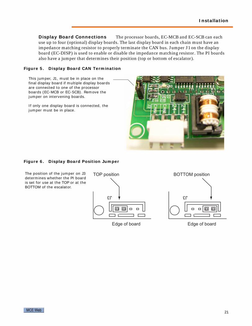
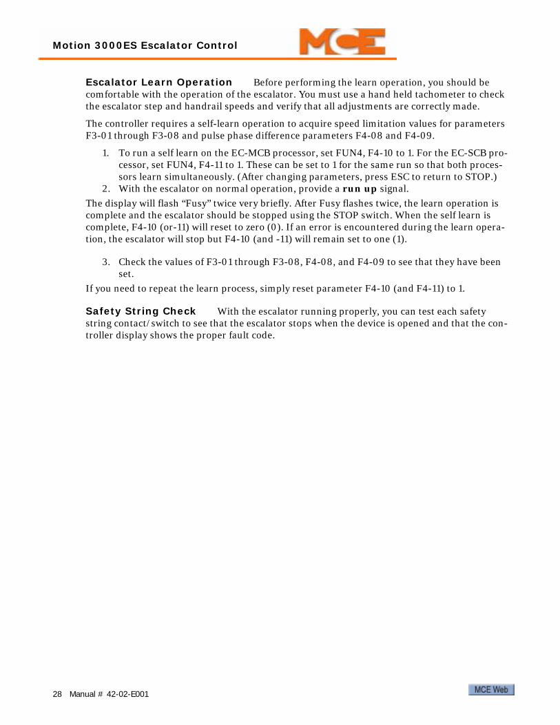
Display Board Connections The processor boards, EC-MCB and EC-SCB can each use up to four (optional) display boards. The last display board in each chain must have an impedance matching resistor to properly terminate the CAN bus. Jumper J1 on the display board (EC-DISP) is used to enable or disable the impedance matching resistor. The PI boards also have a jumper that determines their position (top or bottom of escalator).
Figure 5. Display Board CAN Termination
Figure 6. Display Board Position Jumper
This jumper, J1, must be in place on the final display board if multiple display boards are connected to one of the processor boards (EC-MCB or EC-SCB). Remove the jumper on intervening boards.
If only one display board is connected, the jumper must be in place.
J3
Edge of board
TOP position
J3
Edge of board
BOTTOM positionThe position of the jumper on J3 determines whether the PI board is set for use at the TOP or at the BOTTOM of the escalator.
21

Motion 3000ES Escalator Control
Table 6. EC-SCB Input Connector Descriptions: J1, J2, J3, J4
Terminal No. Function Remark
J1
S6 Step wheel Monitor #1 S6 and S7 monitor direction, step speed, and missing steps for Monitors #1 and #2 respectively.S7 Step wheel Monitor #2
S8 Left handrail speed monitoring Impulse input. Frequency between 0.5-
25HZS9 Right handrail speed
monitoring
J2
P26 Safety circuit Low = Open safety, run disabledHigh = Safety OK, run enabled
P27 Lower left skirt obstruc-tion detection
Active high inputs. Any active input will open the safety string, stopping the esca-lator. Under fault conditions, there will be +24V at these terminals.
P28 Lower right skirt obstruction detection
P29 Lower left comb-step impact detection
P30 Lower right comb-step impact detection
P31 Lower left handrail entry detection
P32 Lower right handrail entry detection
P33 Lower step level detection
J3
P34 Lower step upthrust detection
P35 Lower stop switch
P36 Spare input
Some LCD software versions allow an error message to be programmed for dis-play when P36 is activated: Broken step chain, Tandem fault, Broken belt, Brake wear, Pit flooded, Brake overheat.Program using parameter F4-18.
P37 Spare input
Some LCD software versions allow an error message to be programmed for dis-play when P37 is activated: Pit flooded, Tandem fault, Broken belt, Brake wear, Broken step chain, Brake overheat.Program using parameter F4-19.
P38 Lower entry detector Active with VVVF drive when energy sav-ing mode is selected.
CM10 COM Common for S6 through P38
22 Manual # 42-02-E001

Installation
Please refer to “Display Board Connections” on page 21 for information about properly termi-nating the CAN bus connection to display boards.
Table 7. EC-SCB Output Connector J9
Terminal No. Wye/Delta drive mode ATL and VVVF drive mode
J9
T13 Active when Up or Down contactors are active
Active when UP or DOWN contactors are active or when inverter output is active.
COM common common
T14 Spare output Not used
COM common common
T15 Spare output Not used
COM common common
Table 8. EC-SCB Connector J6
Terminal No. Component Remark
J6
CL1 Connect with the CANL terminal on the EC-MCB Communication between EC-MCB and EC-
SCB; lower entry display board (if equipped); lower LCD panel (if equipped).CH1 Connect with the CANH terminal on the
EC-MCB
24V+DC24V power supply Note polarity. Connect correctly.
24V-
Table 9. EC-SCB Connector J7
Terminal No. Component Remark
J7
CH2 CAN BUS +
Remote monitoringCL2 CAN BUS -
24V- -24VDC (not used)
24V+ +24VDC (not used)
23

Motion 3000ES Escalator Control
Initial System StartupThis section describes initial startup and adjustment.
• Prestart check
• Initial startup
Prestart CheckBefore system startup:
• Check and correct any hazardous conditions
• Check/adjust installed components for:
• Smooth operation
• Proper adjustment to required tolerances
• Lubricate as required:
• Bearings
• Tracks
• Chains
• Guides
• Other hardware
• Ensure that:
• Step bands, skirts, and comb segments are in order
• No debris or equipment is in or on escalator
• All steps are fitted
• Safety devices and protective switches are properly installed
Construction ModeConstruction mode operation allows the escalator to be run on inspection only with a bare min-imum of field wiring installed. For construction mode operation, only the following are needed to run the escalator:
• Motor, brake, and drive (if used)
• Safety String (may be jumpered out initially if necessary)
1. To enter construction mode, set escalator parameter F5-07 to 1 (one). This setting causes all faults to reset automatically while you are making initial adjustments.
• In construction mode, the escalator parameter display will show “-CH-” and the entry displays will show “X”.
2. After completing adjustment, you must set F5-07 back to 0 (zero) before the escalator will enter automatic operation.
• When F5-07 is set back to 0 (zero), the parameter display will show “STOP” and the entry displays will show “SP”.
CautionIf safety devices are bypassed, take extreme caution to avoid personnel injury or equipment damage. As safety equipment is installed, it must be wired into the safety string.
24 Manual # 42-02-E001

Initial System Startup
Initial StartupThe initial startup procedure requires:
• Power up
• Drive (if used) parameter check/set
• Inspection operation
Power Up1. Press the controller Stop button so power is removed from the machine.2. Set the Norm/Insp switch to the Inspection position.
3. Close the main disconnect.
4. Check that controller is powered and drive, if equipped, is on and displaying “inh” (CT) or “noP” (Keb). (Please refer to “CT Drive Fault Displays” on page 52 or page 59 for Keb if the drive trips and displays an error code.)
5. If you have not already done so, check and set if needed, CT drive:
• Motor rated frequency, Hz (0.47)
• Motor rated current, A (0.46)
• Motor rated speed, RPM (0.45)
• Motor rated voltage, V (0.44)
• Maximum frequency, Hz (0.02)
• Acceleration rate, s/100Hz (0.03)
• Deceleration rate, 2/100Hz (0.04)
• Ramp Mode Select = FAST (0.15)
For KEB drives, See “KEB Drive Parameters (VVVF Drive Only)” on page 41 .
6. After checking CT or KEB settings, if equipped, release stop button.
7. Check EC-MCB board indicators to see that:
• P8 is lighted (brake contact) if available
• P5 is lighted (motor/brake contactor proving)
• P6 is lighted (safety string complete)
• P22 is lighted (aux brake contact) if available
8. Check that the escalator control display is showing “X.” Please refer to “Controller Fault Displays” on page 48 if an error code is displayed.
9. Check that all personnel are clear of moving equipment.
Inspection OperationYou are now ready to run the escalator on Inspection to determine that basic operating parame-ters are adequate, acquire self-learned speed limitation parameters, and check that safety string devices are functioning properly.
1. If you are using a remote inspection device, check that it is the only unit plugged in and that the escalator control is set to Norm. If you are running from the buttons on top of the main cabinet, check that the escalator control is set to Insp.
2. Press and hold the Safety button.
3. Press and hold the run up or run down button.
25

Motion 3000ES Escalator Control
Remote Inspection Control Connection Special sockets for connecting remote inspection controls are provided. The sockets are covered and, as soon as a socket cover is opened, the escalator is placed in Inspection mode and stopped. Depending on job require-ments, these sockets may be mounted on the control enclosure and/or remotely in locations specified by the customer.
For any inspection socket to be active, the escalator control must be in Normal mode. If two or more inspection control devices are inadvertently connected at any one time, all inspection sockets are immediately disabled.
Figure 7. Remote Inspection Socket and Control
Brake Pick and Drop Check that the brakes are picking to running clearance. If avail-able, check brake labeling or documentation for recommended pick voltage and verify that the controller is supplying the correct voltage. During initial setup, we recommend setting brake resistance (RB1 and RB2) to three times the resistance across the brake coils for primary and auxiliary brakes. If necessary, adjust brake resistance to achieve the desired drop time.
For PM disk brake control, please refer to the job drawings for brake adjustment instructions and to the mBrake section in this manual for a detailed description.
In order for the remote socket to be active, the controller Inspection/Nor-mal switch must be set to NORM.
26 Manual # 42-02-E001

Initial System Startup
Escalator Braking Distance Feature This feature (not available in all versions of software) measures the stopping distance of the escalator by monitoring the output of the hand-rail proximity sensors at S4 and S5 of the MCB. Immediately upon receiving a stop signal, the MCB counts the number of pulses received at S4 and S5 and determines whether or not the escalator has stopped within a user-defined tolerance.
• If the number of pulses matches the learned value within the programmable stopping dis-tance error, then no error is generated.
• If the number of pulses exceeds the learned value by more than the programmable stop-ping distance error, then E57 “Stop is too long” is generated.
• If the number of pulses is less than the learned value by more than the programmable stopping distance error, then E58 “Stop is too short” is generated.
Associated Parameters
• F3-19 Self-learned Stopping Distance: (0-9999; 0 means feature is disabled)
• F3-20 Stopping Distance Error: (0-99%; default = 50)
1. Be sure that the brake is adjusted correctly so that the escalator is stopping within the desired distance.
2. Enter 1 for parameter F3-19. This enables the feature and allows the MCB to establish a baseline stopping distance the next time a learn function is performed.
3. Perform a learn function. Please refer to “Escalator Learn Operation” on page 28. In order for the stopping distance to be learned, the escalator must be stopped during the learn function. After completing the learn function by stopping the escalator, note that the value of F3-19 has been updated to reflect the baseline stopping distance for the escalator.
Note
To reliably calculate the braking distance, the learned value of F3-19 must be at least 6. If the learned value is less than 6, the handrail wheels will need to be modified such that pulses are generated at a higher frequency. This can be achieved by either making the diameter of the wheels smaller or by adding more surfaces to the wheels that trigger the sensor. If more sur-faces that trigger the sensors are added, all of the surfaces must be equidistant from each other.
Adjust F3-20 to define the stopping distance error. For example, assume F3-19 is determined to be 10 after performing the learn function. If F3-20 is set to 30, this means that the allowable stopping distance is between 7 and 13 counts (10 +/- 30%). If the escalator stops outside of this range, an error message will be generated.
27
Motion 3000ES Escalator Control
Escalator Learn Operation Before performing the learn operation, you should be comfortable with the operation of the escalator. You must use a hand held tachometer to check the escalator step and handrail speeds and verify that all adjustments are correctly made.
The controller requires a self-learn operation to acquire speed limitation values for parameters F3-01 through F3-08 and pulse phase difference parameters F4-08 and F4-09.
1. To run a self learn on the EC-MCB processor, set FUN4, F4-10 to 1. For the EC-SCB pro-cessor, set FUN4, F4-11 to 1. These can be set to 1 for the same run so that both proces-sors learn simultaneously. (After changing parameters, press ESC to return to STOP.)
2. With the escalator on normal operation, provide a run up signal.
The display will flash “Fusy” twice very briefly. After Fusy flashes twice, the learn operation is complete and the escalator should be stopped using the STOP switch. When the self learn is complete, F4-10 (or-11) will reset to zero (0). If an error is encountered during the learn opera-tion, the escalator will stop but F4-10 (and -11) will remain set to one (1).
3. Check the values of F3-01 through F3-08, F4-08, and F4-09 to see that they have been set.
If you need to repeat the learn process, simply reset parameter F4-10 (and F4-11) to 1.
Safety String Check With the escalator running properly, you can test each safety string contact/switch to see that the escalator stops when the device is opened and that the con-troller display shows the proper fault code.
28 Manual # 42-02-E001

Operating Adjustments
Operating AdjustmentsBoth the controller and the VVVF drive (if used) allow adjustment of many operating character-istics. You will need to adjust each for optimal performance of the escalator installation. This section contains complete controller and drive parameter tables.
Keypad Refresher
• ESC button: Press to exit parameter settings without saving changes.
• DOWN button: Move down in parameter settings list. Move between digits of a selected value.
• UP button: Move up in parameter settings list. Change the value of a selected digit. (Digit will be flashing when its value can be changed.)
• OK: Select/Save.
• At the highest level, parameters are grouped under seven functions, FUN1 through FUN7.
• Within each function, parameters are listed numerically by function and parameter order (i.e., F1-01 is the first parameter of function FUN1, F1-02 is the second, etc.).
• Consult the complete parameter table for an ordered list of all parameters.
Controller ParametersSee “Controller Parameters” on page 30 for specific information. To display and change con-troller parameters:
1. Press OK to access the function menu.2. Press the Up or Down button to scroll through the main menus (FUN3-FUN7).
3. Press OK to enter the displayed menu.
4. Use Up or Down to scroll to the desired parameter.
5. Press OK to display the parameter value.
6. Use the Down button to move between digits of a displayed value.
7. Use the Up button to change the value of a selected (flashing) digit.
8. Press OK to save the new value.
9. “Yes” will flash briefly indicating that the new value has been saved.
10. Press ESC at any time to exit the menu without making changes (before pressing OK).
Faults If a fault number is displayed:
1. Please refer to “Controller Fault Displays” on page 48 for a fault description.2. Correct the fault.
3. Press and hold the Up and Down buttons simultaneously for three seconds to clear the fault display.
29

Motion 3000ES Escalator Control
Table 10. Controller Parameters
Param Name Description Value Default MCE
FUN1-Logic Input Settings
F1-01 Contact on Brake Set the correct polarity of Brake Con-tact or to disable this feature
0=NC1=NO2=Disable
1
F1-02 Contact on Auxil-iary brake
Set the correct polarity of Auxiliary brake contact or to disable or to cancel this feature
0=NC1=NO2=Cancel3=Disable
2
F1-03 Upper entry detection switch
With VVVF drive & energy-saving con-trol, upper entry detecting switch input setting
0=NC1=NO 1
F1-04 Lower entry detection switch
With VVVF drive & energy-saving con-trol, lower entry detecting switch input setting
0=NC1=NO 1
FUN2- Timer Menu
F2-01 Oil timer interval Oil ---- time interval setting 0-9999 min 120
F2-02 Oil Timer dura-tion setting Oil ---- duration setting 0-9999 sec 6
F2-03 Speed Pick Delay
In VVVF drive mode, delay from brake picked to motor run mode. Program to 1000 for VVVF application.In ATL mode, this feature is not used. Program to default setting 1000In Wye/Delta mode, delay from brake picked to Wye contactor Closed. Pro-gram to 500 for Wye/Delta application
0-9999 millisec 1000
F2-04 Up/Dn to Delta delay
Wye/Delta only. Delay from Wye con-tactor enable to Delta contactor enable 0-9999 millisec 1000 1000
F2-05 Month /Date Set-ting System time setting: Month /Date MM/DD 0000 Month/Date
F2-06 Hour/Minute Set-ting
System time setting: Hour/Minute (24-hour clock) HH/MM 0000 Hour/Minute
F2-07 Reduced Speed Timer
Duration setting from high speed to low speed operation
1-9999 sec0=disabled 60
F2-08 Auto-Stop Timer
Duration setting from low speed opera-tion to stop/standby. If set to “0”, F4-05 automatic direction switching is dis-abled.
1-9999 sec0=disabled 0
F2-09 Handrail Over-speed Delay
Delay time of the speed fault checking for left and right handrail 0-9 sec 4 4
F2-10 Smoke Detector Delay
Delay time setting for fire alarm fault inspection 0-30 sec 15 15
F2-11 Alarm Timer at start
Alarm bell output time setting before the Escalator start 0-9 sec 1 1
30 Manual # 42-02-E001

Operating Adjustments
F2-12 Stop Delay
PM Contactor and Brake drop delay setting.Program to 900msec for VVVF drive/ATL and 0 sec for Wye/Delta.If system is equipped with Motor Effi-ciency Controller, set to 200.
0-5000Msec 500
F2-13 Y/D Open Transi-tion Timer Wye-Delta Open Transition Timer 0-5000Msec 0 100
F2-14 Alarm Shutoff Timer Alarm Bell output Shutoff Timer 0-60 min 0 10
FUN3- Speed Monitoring
F3-01 Step speed S2 Terminal S2 on EC-MCB: Speed check-ing 1 for step wheels/direction 0-9999 units 1
Learned Speed check-ing 1 for step speeds
F3-02 Step speed S3 Terminal S3 on EC-MCB: Speed check-ing 2 for step wheels/direction 0-9999 units 1
Learned Speed check-ing 2 for step speeds
F3-03 Left handrail speed S4
Terminal S4 on EC-MCB: Speed check-ing for left handrail 0-9999 units 1
Learned speed check-ing for Left handrail
F3-04 Right handrail speed S5
Terminal S5 on EC-MCB: Speed check-ing for right handrail 0-9999 units 1
Learned speed check-ing for Right handrail
F3-05 Step speed S6 Terminal S6 on EC-SCB: Speed check-ing 1 for step wheels 0-9999 units 1
Learned Speed check-ing 1 for step speeds
F3-06 Step speed S7 Terminal S7 on EC-SCB: Speed check-ing 2 for step wheels 0-9999 units 1
Learned Speed check-ing 2 for step speeds
F3-07 Left handrail speed S8
Terminal S8 on EC-SCB: Speed check-ing for left handrail 0-9999 units 1
Learned speed check-ing for Left handrail
F3-08 Right handrail speed S9
Terminal S9 on EC-SCB: Speed check-ing for right handrail 0-9999 units 1
Learned speed check-ing for Right handrail
F3-09 Speed error on S2
Set Upper and Lower speed limit for S2 using the percentage of value of F3-01. 0-99% 15 15
F3-10 Speed error on S3
Set Upper and Lower speed limit for S3 using the percentage of value of F3-02. 0-99% 15 15
F3-11 Speed error on S4
Set Upper and Lower speed limit for S4 using the percentage of value of F3-03. 0-99% 15 15
F3-12 Speed error on S5
Set Upper and Lower speed limit for S5 using the percentage of value of F3-04. 0-99% 15 15
Table 10. Controller Parameters
Param Name Description Value Default MCE
31

Motion 3000ES Escalator Control
F3-13 Speed error on S6
Set Upper and Lower speed limit for S6 using the percentage of value of F3-05. 0-99% 15 15
F3-14 Speed error on S7
Set Upper and Lower speed limit for S7 using the percentage of value of F3-06. 0-99% 15 15
F3-15 Speed error on S8
Set Upper and Lower speed limit for S8 using the percentage of value of F3-07. 0-99% 15 15
F3-16 Speed error on S9
Set Upper and Lower speed limit for S9 using the percentage of value of F3-08. 0-99% 15 15
F3-17 Missing step on EC-MCB
Top missing steps detecting by S2, S3 on EC-MCB 0-9999 0
Enter same as learned value of parameter F3-01
F3-18 Missing step on EC-SCB
Bottom missing steps detecting by S6, S7 on EC-SCB 0-9999 0
Enter same as learned value of parameter F3-05
F3-19 Self-learned stop-ping distance
Learned stopping distance. Not avail-able on all software versions. 0-9999 0 Set automat-
ically
F3-20 Stopping dis-tance error
Sets upper and lower stopping distance limit using the percentage of value of F3-19. Not available on all software versions.
0-99% 0
F3-21 Missing step at low speed
VVVF systems only. Scales learned step speed so that missing step can be detected at low speed during energy saving mode. Not available on all soft-ware versions.
0-99% 0
FUN4- Advanced Configuration
F4-01 Motor control Selects VVVF/ATL or Wye/Delta drive mode
0=VVVF or ATL1= Wye/Del 0
F4-02 Arrow display mode Display mode of the EC-DISP Board 0=big arrow
1=small arrow 0 0
F4-03 EC-SCB enable Determines if the EC-SCB board is used for control redundancy (read) or not.
0=No1=Yes 1 1
F4-04 Oil device type Type of the oil device0=motor1=electromag-netic Valve
1 1
F4-05 Energy saving mode
Determines escalator automatic speed mode selection (VVVF drive only).
0= Normal (Single speed)1= Energy Sav-ing (2 spd, starting direc-tion only)2= Intelligent (2 spd, 2 directions based on entry detect)
0
F4-06 Rev insp enable on EC-MCB
Applied reversal inspection on EC-MCB or not
0=No1= Yes 0 1
Table 10. Controller Parameters
Param Name Description Value Default MCE
32 Manual # 42-02-E001

Operating Adjustments
F4-07 Rev detect enable on EC-SCB
Applied reversal detection on EC-SCB or not
0=No1= Yes 0 1
F4-08Pulse phase dif-ference on EC-MCB
Pulse phase difference on EC-MCB.Automatically set when a self-learn operation is run for this processor. See F4-10.
0 – 99 0 Set automati-cally
F4-09Pulse phase dif-ference on EC-SCB
Pulse phase difference on EC-SCBAutomatically set when a self-learn operation is run for this processor. See F4-11.
0 - 99 0 Set automati-cally
F4-10 Self-learn on EC-MCB
Used to enable a self-learn operation for the EC-MCB board.
0=disabled1=enabled 1 0
F4-11 Self-learn on EC-SCB
Used to enable a self-learn operation for the EC-SCB board.
0=disabled1=enabled 1 0
F4-12 P2(Run) enable on EC-MCB P2 (“RUN”) on EC-MCB is used or not 0=No
1=Yes 1
F4-13 Fault latch setting P9-P27
Faults Latch or Unlatch A=P9, P10, P11 B=P12, P13, P14, C=P15, P16, P17 D=P18, P24, P27
0=Latch1-7 = Unlatch
0 0 0 0 D C B A
5017 (See note follow-ing table)
F4-14 Fault latch setting P28-P37
Faults Latch or Unlatch A=P28, P29, P30 B=P31, P32, P33, C=P34, P36, P37 D= N/A, N/A, N/A
0=Latch1-7 = Unlatch
0 0 0 0
D C B A
0101 (See note follow-ing table)
F4-15 Escalator number Escalator ID for remote monitoring.Not available on all software versions. 0-9999 0 0
F4-16 P9 Enable
Programmable error message:1. Reverse Phase2. Speed Governor3. Reverse Phase or MEC Fault4. MEC faultNot available on all software versions.
1-4 1 1
F4-17 P24 Enable
Programmable error message:1. Seismic Fault2. Tandem Fault3. Broken Belt4. Brake Wear5. Broken Step Chain6. Brake Overheat7. Speed GovernorNot available on all software versions.
1-6 1 1
F4-18 P36 Enable
Programmable error message:1. Broken Step Chain2. Tandem Fault3. Broken Belt4. Brake Wear5. Pit Flooded6. Brake OverheatNot available on all software versions.
1-6 1 1
Table 10. Controller Parameters
Param Name Description Value Default MCE
33

Motion 3000ES Escalator Control
F4-19 P37 Enable
Programmable error message:1. Pit Flooded2. Tandem Fault3. Broken Belt4. Brake Wear5. Broken Step Chain6. Brake OverheatNot available on all software versions.
1-6 1 1
FUN5-Counters & Fault HistoryF5-01 Password setting Set passcode: default is 00000000.F5-02 Usage time limit Limitation of the use time 0-9999hr 0
F5-03 Usage time bal-ance The rest of the use time 0-9999hr 0
F5-04 Clear fault log Clears the F6-01 fault history.
F5-05 Parameter Default
Resets all controller parameters to their default values.
F5-06 Start counter Operational Counter 0-9999
F5-07 Construction Mode Construction Mode 0=OFF
1=ON 0
FUN6-Fault DisplayF6-01 Fault display Fault display
FUN7- Software Ver. for EC-MCB
F7-01 Software version. Software version.
FUN8- Software Ver. for EC-SCB
F8-01 Software version Software version
Table 10. Controller Parameters
Param Name Description Value Default MCE
34 Manual # 42-02-E001

Operating Adjustments
Note
Parameters in the preceding table that reference this note are set by entering a number (1 - 7) in the displayed digit that corresponds to the group of switches you want to set. For example, entries shown in the tables below would result in the settings shown in the shaded area below the entry.
• When set to 0, input latches
• When set to 1, input does not latch
• In this example, P24, 17, 16, 15, 14, and 13 are 0 (latching inputs) while P27, 18, 12, 11, 10, and 9 are 1 (non-latching inputs)
• In this example, P37, 36, 33, 32, 31, 30, and 29 are 0 (latching inputs) while P34 and P28 are 1 (non-latching inputs).
Table 11. F4-13 Default Setting
Entry: 5 Entry: 0 Entry: 1 Entry: 7
Switch Group D Switch Group C Switch Group B Switch Group AP27 P24 P18 P17 P16 P15 P14 P13 P12 P11 P10 P90 0 0 0 0 0 0 0 0 0 0 00 0 1 0 0 1 0 0 1 0 0 10 1 0 0 1 0 0 1 0 0 1 00 1 1 0 1 1 0 1 1 0 1 11 0 0 1 0 0 1 0 0 1 0 01 0 1 1 0 1 1 0 1 1 0 11 1 0 1 1 0 1 1 0 1 1 01 1 1 1 1 1 1 1 1 1 1 1
Table 12. F4-14 Default Setting
Entry: 0 Entry: 1 Entry: 0 Entry: 1
Switch Group D Switch Group C Switch Group B Switch Group AN/A N/A N/A P37 P36 P34 P33 P32 P31 P30 P29 P280 0 0 0 0 0 0 0 0 0 0 00 0 0 0 0 1 0 0 1 0 0 10 0 0 0 1 0 0 1 0 0 1 00 0 0 0 1 1 0 1 1 0 1 10 0 0 1 0 0 1 0 0 1 0 00 0 0 1 0 1 1 0 1 1 0 10 0 0 1 1 0 1 1 0 1 1 00 0 0 1 1 1 1 1 1 1 1 1
35

Motion 3000ES Escalator Control
Displaying Parameters in Real TimeWhen the escalator is running, you can cycle through parameters to check their settings by pressing the UP or DOWN buttons on the display/keypad. The system must be running in Nor-mal mode for the parameters to be viewed in real time.
• RUNT: Running time.• USP1: Speed from S2 on EC-MCB.• USP2: Speed from S3 on EC-MCB.• USP3: Speed from S4 on EC-MCB.• USP4: Speed from S5 on EC-MCB.• DSP1: Speed from S6 on EC-SCB.• DSP2: Speed from S7 on EC-SCB.• DSP3: Speed from S8 on EC-SCB.• DSP4: Speed from S9 on EC-SCB.• RSTU: Operating status.• CLOC: Current time.• UPNP: Pulse phase differences on EC-MCB.• DPNP: Pulse phase differences on EC-SCB.• Cn-H: CAN high.• Cn-L: CAN low.
36 Manual # 42-02-E001
Operating Adjustments
CT Drive Parameters (VVVF Drive Only)
StatusIn status mode, the drive display shows the operating status of the drive:
• Auto tune: Auto tune in progress.
• inh: Inhibited; enable input is inactive.
• rdY: Ready; enable closed but inverter not active.
• StoP: Stopped; inverter active but holding zero speed/frequency.
• run: Running; inverter active and motor running.
• SCAN: Drive is trying to synchronize in regen mode.
• ACUU: Power mains lost; decelerating to zero in mains loss ride-through or stop modes.
• dEC: Decelerating; speed/frequency ramping to zero after a stop.
• dc: DC injection; DC injection stop active.
• POS: Position; position control active during orientation stop.
• triP: Tripped; drive has tripped.
• act: Active; regen unit is synchronized and inverter is active.
Displaying Drive ParametersIn parameter view mode, the first display row shows the menu parameter number and the sec-ond the value of that parameter. To display drive parameters and check their current settings:
1. Use the mode button to select parameter view mode (upper line flashing in drive
display).2. Use left and right arrows on rocker switch to select a menu.
3. Use up and down arrows on the rocker switch to select a parameter.
• Press up and down arrows simultaneously to return to the first parameter in a menu.
• Press left and right arrows simultaneously to return to Menu 0 (zero).
• The drive remembers the last parameter being viewed so when you leave, then return to parameter view mode, that parameter will be displayed.
37

Motion 3000ES Escalator Control
Editing Drive ParametersTo change drive parameters:
1. Display the parameter.2. Use the mode button to select parameter edit mode (lower line flashing in drive dis-
play).
3. Use up and down arrows on rocker switch to change value.
4. Press the mode button to exit edit mode.
• Optionally, choose a particular digit to edit using the left or right arrows.
• Press and hold up or down arrows to change value continuously.
• Press and hold up and down arrows simultaneously to set a value to 0 (zero).
• Value entry above maximum or below minimum for parameter is not allowed.
Once you have set parameters as desired, you must do the following to save them:
1. Enter 1000 in parameter 0.00. (If the drive is in under voltage trip state or being sup-plied from a 48V backup source, 1001 must be entered instead.)
2. Press the drive reset button.
Running the Motor from the KeypadYou are able to run the motor manually from the drive keypad:
1. Set parameter Pr 1.14 to 4 to enable Stop and Run buttons.2. If desired, the Reverse button may be enabled through Pr 6.13.
3. Adjust frequency/speed using Pr 1.17 (see note below).
Note
Pr 1.17 is a read only parameter than can only be adjusted in status mode using the Up or Down buttons. With keypad control active, pressing Up or Down in status mode causes the drive to automatically display the keypad reference and adjust it in the relevant direction. This can be done whether the drive is disabled or running. Reference units for different modes are:- Open loop: Hz- Closed loop: RPM- Servo: RPM
Refer to the drive manual for detailed information.
38 Manual # 42-02-E001
Operating Adjustments
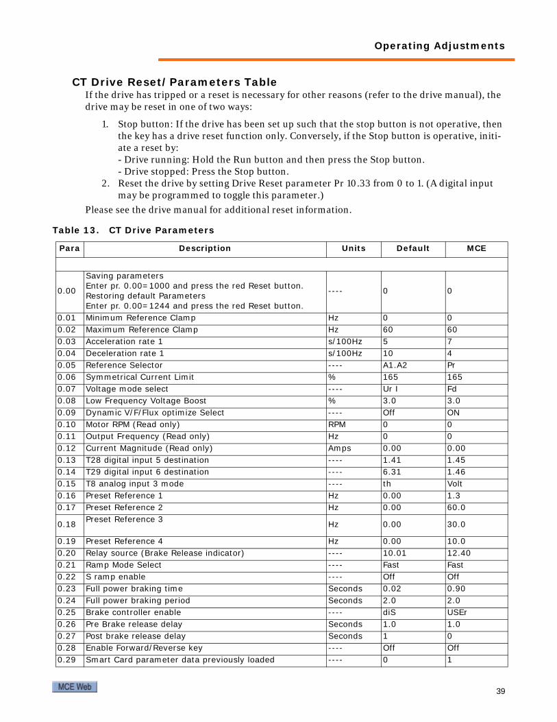
CT Drive Reset/Parameters TableIf the drive has tripped or a reset is necessary for other reasons (refer to the drive manual), the drive may be reset in one of two ways:
1. Stop button: If the drive has been set up such that the stop button is not operative, then the key has a drive reset function only. Conversely, if the Stop button is operative, initi-ate a reset by:- Drive running: Hold the Run button and then press the Stop button.- Drive stopped: Press the Stop button.
2. Reset the drive by setting Drive Reset parameter Pr 10.33 from 0 to 1. (A digital input may be programmed to toggle this parameter.)
Please see the drive manual for additional reset information.
Table 13. CT Drive Parameters
Para Description Units Default MCE
0.00
Saving parametersEnter pr. 0.00=1000 and press the red Reset button.Restoring default ParametersEnter pr. 0.00=1244 and press the red Reset button.
---- 0 0
0.01 Minimum Reference Clamp Hz 0 00.02 Maximum Reference Clamp Hz 60 600.03 Acceleration rate 1 s/100Hz 5 70.04 Deceleration rate 1 s/100Hz 10 40.05 Reference Selector ---- A1.A2 Pr0.06 Symmetrical Current Limit % 165 1650.07 Voltage mode select ---- Ur I Fd0.08 Low Frequency Voltage Boost % 3.0 3.00.09 Dynamic V/F/Flux optimize Select ---- Off ON0.10 Motor RPM (Read only) RPM 0 00.11 Output Frequency (Read only) Hz 0 00.12 Current Magnitude (Read only) Amps 0.00 0.000.13 T28 digital input 5 destination ---- 1.41 1.450.14 T29 digital input 6 destination ---- 6.31 1.460.15 T8 analog input 3 mode ---- th Volt0.16 Preset Reference 1 Hz 0.00 1.30.17 Preset Reference 2 Hz 0.00 60.0
0.18 Preset Reference 3 Hz 0.00 30.0
0.19 Preset Reference 4 Hz 0.00 10.00.20 Relay source (Brake Release indicator) ---- 10.01 12.400.21 Ramp Mode Select ---- Fast Fast0.22 S ramp enable ---- Off Off0.23 Full power braking time Seconds 0.02 0.900.24 Full power braking period Seconds 2.0 2.00.25 Brake controller enable ---- diS USEr0.26 Pre Brake release delay Seconds 1.0 1.00.27 Post brake release delay Seconds 1 00.28 Enable Forward/Reverse key ---- Off Off0.29 Smart Card parameter data previously loaded ---- 0 1
39

Motion 3000ES Escalator Control
* in the table above means that the value is set as required by customer job requirements.
0.30 Parameter Cloning ---- None None0.31 Drive Voltage Rating Voltage 400/2000.32 Maximum Heavy Duty Rating (Read Only) Amps 00.33 Catch a Spinning Motor ---- 0 00.34 User Security Code ---- 0 00.35 Serial Comms Mode ---- rtu rtu0.36 Baud Rate ---- 19200 192000.37 Serial Address ---- 1 10.38 Current Loop Kp Gain ---- 20 200.39 Current Loop Ki Gain ---- 40 400.40 Auto Tuning ---- 0 00.41 Maximum Switching Frequency KHz 3 (8Khz) 3 (8Khz)0.42 Number of motor poles Poles Auto0.43 Rated Motor Power Factor ---- 0.85 0.850.44 Rated Motor Voltage Volts 460/2300.45 Rated load rpm / rated speed RPM 18000.46 Motor Rated Current Amps 00.47 Motor Rated Frequency Hz 600.48 User Drive Mode of Operation ---- Open Loop Open Loop0.49 Security Status ---- L1 L20.50 Drive Software Version 1.11 or >
Menu 2: Ramps02.08 Standard Ramp Voltage Volts 775 775Menu 8: Digital I/O8.23 T26 Digital I/O 3 destination ---- 6.30 6.308.24 T29 Digital I/O 4 destination ---- 6.32 6.32Menu 11: General Drive Setup11.22 Parameter displayed at power-up ---- 0.10 0.10
Menu 12: Slot 3 Setup17.13 Enable auto run ---- ON, 0FF OFF
Table 13. CT Drive Parameters
40 Manual # 42-02-E001

Operating Adjustments
KEB Drive Parameters (VVVF Drive Only)Normal Mode (Single Speed):
Up Going: Drive is always in control. Energy savings are realized when the escalator has a light load because the drive can provide less voltage and current while maintaining contract speed. When the load increases, the drive automatically increases voltage and current (only 2 modes—rated current and less current, not variable).
Down Going: At start, drive accelerates escalator to contract speed (soft start to 60Hz). Once contract speed is reached, the drive drops PM and picks PML. This switches power to the line. In this configuration, power can be put back on the line if the load of the down going escalator causes the motor to act like a generator.
Inspection speed is adjustable.
Energy Saving Modes (when code allows speed change during operation)Sensors are mounted at the top and bottom entries to the escalator in order to detect someone approaching or exiting the escalator.
Energy Saving Mode (Two Speeds, Starting Direction Only)After there has been no activity for a user-defined period, the escalator will change from high speed to low speed. When an entry detector senses someone approaching the escalator, the speed is increased from low to high. An additional timer can be set to stop the escalator com-pletely after there has been no activity for a user-defined period at slow speed. In this case, when an entry detector senses someone approaching the escalator, the escalator changes from a stopped condition to high speed in the starting direction only.
Intelligent Mode (Two Speeds, Two Directions Based on Entry Detection)After there has been no activity for a user-defined period, the escalator will change from high speed to low speed. When an entry detector senses someone approaching the escalator, the speed is increased from low to high. An additional timer can be set to stop the escalator com-pletely after there has been no activity for a user-defined period at slow speed. In this case, when an entry detector senses someone approaching the escalator, the escalator changes from a stopped condition to high speed AND goes in the direction determined by the entry detector.
41


Motion 3000ES Escalator Control
Table 14. KEB F5 Parameters for Escalator Applications
WARNING: Do not change drive parameters while escalator is running. Incorrect drive parameters can cause erratic operation.WARNING: Parameters with an asterisk (*) must be set correctly for your specific motor/machine/job.
Param Description Unit Default MCE
CP.00 Password - - -CP.01 Motor Rated Power (KW = HP x 0.75) KW 7.5CP.02 Motor Rated Current ACP.03 Motor Electronic Overload Current ACP.04 Motor Rated Voltage V 460 *CP.05 Motor Rated Frequency Hz 60 *CP.06 Motor Rated Power Factor - 0.85 0.85CP.07 Motor Rated Frequency Hz 60 *CP.08 Low Speed Torque Boost % 5.0 5.0CP.09 Voltage Regulation (Set equal to motor voltage) V 460 *CP.10 Energy Saving Factor % 50 ** 50CP.11 Low Speed (recommend 50% of High Speed CP.13) Hz 10.0000 **CP.12 Inspection Speed Hz 35.0000 ** 10.0000CP.13 High Speed Hz 60.0000 **CP.14 Line Frequency (Set 1Hz lower than line frequency) Hz 59.0000CP.15 Acc Time sec 5.00 **5.00CP.16 Dec Time sec 5.00 **5.00CP.17 Drive Contactor Turn OFF Timer mSec 100.00 100.00CP.18 Drive Contactor Turn ON Timer mSec 1000.00 1000.00CP.19 Line Contactor Turn ON Timer mSec 1000.00 1000.00CP.20 Energy Saving Trigger Level. (Set 2A higher than idle current
running full speed up. Monitor CP.21 to see actual current.)A - CP.21 + 2A
CP.21 Phase Current A - Read OnlyCP.22 Peak Phase Current (Press Down key to reset) A - Read OnlyCP.23 Actual Frequency Display Hz - Read OnlyCP.24 Output Voltage V - Read OnlyCP.25 Actual DC Voltage V - Read OnlyCP.26 Peak DC Voltage (Press Down key to reset) V - Read OnlyCP.27 Input terminal state. (Display active inputs. See Table 17 for
decoding values)- 0: no
inputRead Only
CP.28 Inverter State - - Read OnlyCP.29 Function select (Selects which functions are active. See Table
16 for available setting.) - 4
CP.30 Escalator status mode (Display current mode of operation. See Table 15 to decode number.)
- - Read Only
44 Manual # 42-02-E001

Operating Adjustments
CP Mode to User Mode: To access user mode parameters (OS and dF), set CP.00 to 660.User Mode to CP Mode: Set OS.01 to 100 to go back to CP Mode.Note: Do not change these parameters unless directed by MCE engineer or tech support.
OS.00 Operator Type - - 80131OS.01 Password - - -OS.02 Software Date - - -OS.04 Diag Response Delay Time - - 1OS.05 Diag baud Rate - - 38400OS.06 Auto Reset Fault - - 5dF.00 Machine Download (n3000 = Escalator Program) - n3000 n3000* Parameters are motor/machine/job dependent.** Recommended but field adjustable.
Table 15. KEB CP.30 Escalator Mode Status Table
Value State Value State Value State0 Idle 15 Up Inspection 30 Down Brake Off1 No Enable Error 16 Up Low Speed 31 Down Start
2 No Enable Wait for Direc-tion Drop 17 Up Low to High Speed Accel. 32 Down Inspection
3 Kill Contacts 18 Up High Speed 33 Down Low Speed4 Stopped 19 Up High to Low Speed 34 Down High Speed
5 Wait for Enable 20 Up Low Time Delay Energy Saving 35 Down Decel
6 Up Wait for Enable 21 Up Low Energy Saving Active 36 Down Low Time Delay Energy Saving
7 Up Enabled 22 Up High Time Delay Energy Saving 37 Down Low Energy Saving
Active8 Up Brake Off 23 Up High Energy Saving Active 38 Down High Line Operation
9 Brake On 24 Up High Line Operation 39 Down Drive and Line Con-tactor Off
10 Modulation Off 25 Up Drive and Line Contactor Off 40 Down High Speed Search
Active
11 Turn Off Time Delay Drive Contactor 26 Up High Speed Search Active 41 Down Speed Search Timer
12 Up Start 27 Up Speed Search Timer13 Fast Stop 28 Down Wait for Enable14 Up Decel 29 Down Enabled
Table 14. KEB F5 Parameters for Escalator Applications
WARNING: Do not change drive parameters while escalator is running. Incorrect drive parameters can cause erratic operation.WARNING: Parameters with an asterisk (*) must be set correctly for your specific motor/machine/job.
Param Description Unit Default MCE
45

Motion 3000ES Escalator Control
Table 16. KEB Function Selection
Value State Value State Value State
0 No Function Active 2 Energy Saving Up all Speeds Active 8 Line Contactor Enabled for
High Speed Up Operation.
1 Energy Saving Down Low Speed Active 4 Line Contactor Enabled for
High Speed Down OperationTo select more than one function, add the respective numbers together and enter the total value.
Table 17. KEB Input Status
Value State Value State Value State
0 No Inputs Active. 68 Low Speed and Up Active 137 High Speed, Enable, and Down Active
1 Enable Active 69 Low Speed, Enable, and Up Active 192 Inspection Speed Active
2 Reset Active 72 Low Speed and Down Active 193 Inspection Speed and Enable Active
4 Up Active 73 Low Speed, Enable, and Down Active 196 Inspection Speed and Up
Active
5 Up and Enable Active 128 High Speed Active 197 Inspection Speed, Enable, and Up Active
8 Down Active 129 High Speed and Enable Active 200 Inspection Speed and Down
Active
9 Down and Enable Active 132 High Speed and Up Active 201 Inspection Speed, Enable, and Down Active
64 Low Speed Active 133 High Speed, Enable, and Up Active
65 Low Speed and Enable Active 136 High Speed and Down Active
46 Manual # 42-02-E001

Commissioning Tests
Commissioning TestsOverspeed and reversal errors may need to be demonstrated during commissioning tests.
Step Overspeed Error1. After completing a learn run at contract speed, record the values for parameters F3-01,
F3-02, F3-05, and F3-06. They should all be very close to the same number. (They are learned speeds from the four step sensors.)
2. Manually change one of the step sensors parameters to a value 20% more than the learned value.
3. Record the handrail learned values (F3-03, F3-04, F3-07, and F3-08). Set all of them to 0 (zero) to temporarily disable handrail speed checking.
4. Start the escalator and observe that an overspeed error is generated.
5. Set the changed step sensor value and the four handrail values back to the recorded set-tings.
Regarding the preceding test, the error was generated because the controller was expecting the time between pulses to be 1200 mS when it was actually 1000 mS. This is greater than the allowed error (default is 15% as defined by parameter F3-09) so the overspeed error was gener-ated. Note that the learned values represent time between sensor pulses so, the lower the num-ber, the higher the frequency of the pulse (or, the faster the steps are travelling).
ReversalFor this test, parameters F4-06 and F4-07 must be set to 1 to enable reversal detection.
1. After completing a learn run, switch the inputs at S2 and S3 on the J1 connector of the EC-MCB board.
2. Start the escalator. Observe that a reversal fault, E-01, is generated.
3. Return the S2 and S3 connections to the correct positions.
47

Motion 3000ES Escalator Control
Fault ConditionsBoth the controller and the VVVF drive (if used) will display fault condition codes. This section contains complete controller and drive fault condition tables and descriptions.
Controller Faults
Note
To reset a latched fault, press both UP and DOWN buttons and hold them down for two sec-onds.
Terminals P10 through P18, P20, and P21 on the EC-MCB and terminals P27 through P34 on the EC-SCB are assignable to different functions. The following table lists faults for these termi-nals as they are normally assigned by MCE. There is a generic table following this one with spaces to write the devices monitored by your system if changes have been made or your system does not conform to the standard.
Table 18. Controller Fault Displays
Fault Description Troubleshooting
E-01Reversal detection fault on EC-MCB. S2 and S3 input on J1 of EC-MCB.
Confirm that F4-08 is set to the same value as UPNP when escalator is going UP. If not, refer to the Escalator Learn Operation to re-learn Verify that sensors are spaced < 1/2 tread width apart.
E-02
Overspeed fault. Step Speed/Missing Step monitoring using upper sensor 1. S2 input on J1 of EC-MCB.
Check connection and function of input device.Confirm that F3-01 is set to the same value as USP1. If not, refer to the Escalator Learn Operation to re-learn parameter F3-01.Check escalator mechanical integrity.
E-03
Overspeed fault. Step Speed/Missing Step monitoring using upper sensor 2. S3 input on J1 of EC-MCB.
Check connection and function of input device.Confirm that F3-02 is set to the same value as USP2. If not, refer to the Escalator Learn Operation to re-learn parameter F3-02.Check escalator mechanical integrity.
E-04Overspeed fault. Left handrail speed monitoring. S4 input on J1 of EC-MCB.
Check connection and function of input device.Confirm that F3-03 is set to the same value as USP3. If not, refer to the Escalator Learn Operation to re-learn parameter F3-03.Check escalator mechanical integrity.
E-05Overspeed fault. Right hand-rail speed monitoring. S5 input on J1 of EC-MCB.
Check connection and function of input device.Confirm that F3-04 is set to the same value as USP4. If not, refer to the Escalator Learn Operation to re-learn parameter F3-04.Check escalator mechanical integrity.
E-06
Underspeed fault. Step Speed/Missing Step monitor-ing using upper sensor 1. S2 input on J1 of EC-MCB.
Check connection and function of input device.Confirm that F3-01 is set to the same value as USP1. If not, refer to the Escalator Learn Operation to re-learn parameter F3-01.Check escalator mechanical integrity.
E-07
Underspeed fault. Step Speed/Missing Step monitor-ing using upper sensor 2. S3 input on J1 of EC-MCB.
Check connection and function of input device.Confirm that F3-02 is set to the same value as USP2. If not, refer to the Escalator Learn Operation to re-learn parameter F3-02.Check escalator mechanical integrity.
E-08Underspeed fault. Left hand-rail speed monitoring. S4 input on J1 of EC-MCB.
Check connection and function of input device.Confirm that F3-03 is set to the same value as USP3. If not, refer to the Escalator Learn Operation to re-learn parameter F3-03.Check escalator mechanical integrity.
E-09 Reverse phase fault. P9 input on J2 of EC-MCB.
Check input device to P9 terminal. May be used for Speed Governor or Motor Efficiency Controller depending on configuration.
48 Manual # 42-02-E001

Fault Conditions
E-10 Motor overheat fault. P10 input on J2 of EC-MCB. Check input device to P10 terminal.
E-11 Upper left missing skirt fault. P11 input on J3 of EC-MCB. Check input device to P11 terminal.
E-12Upper right missing skirt fault. P12 input on J3 of EC-MCB.
Check input device to P12 terminal.
E-13Upper left comb-step impact fault. P13 input on J3 of EC-MCB.
Check input device to P13 terminal.
E-14Upper right comb-step impact fault. P14 input on J3 of EC-MCB.
Check input device to P14 terminal.
E-15Upper left handrail entry fault. P15 input on J3 of EC-MCB.
Check input device to P15 terminal.
E-16Upper right handrail entry fault. P16 input on J3 of EC-MCB.
Check input device to P16 terminal.
E-17 Upper step sag fault. P17 input on J3 of EC-MCB. Check input device to P17 terminal.
E-18 Upper step upthrust fault. P18 input on J3 of EC-MCB. Check input device to P18 terminal.
E-19 Drive chain broken fault. P19 input on J4 of EC-MCB. Check input device to P19 terminal.
E-20
Missing step fault. S2 and S3 input on J1 of EC-MCB or S6 and S7 input on J1 of EC-SCB.
Check input device to S2 and S3 terminals.
E-21 Smoke detector fault. P21 input on J4 of EC-MCB. Check input device to P21 terminal.
E-24Run direction input fault. P3 and P4 inputs on J2 of EC-MCB.
Check mechanics of both upper and lower escalator starting switches.Check for proper operation of Up and Down inputs to P3 and P4 termi-nals.
E-25Run direction input fault at power up. P3 and P4 inputs on J2 of EC-MCB.
Check mechanics of both upper and lower escalator starting switches.Check for proper operation of Up and Down inputs to P3 and P4 termi-nals.
E-27 Lower left missing skirt fault. P27 input on J2 of EC-SCB. Check input device to P27 terminal.
E-28Lower right missing skirt fault. P28 input on J2 of EC-SCB.
Check input device to P28 terminal.
E-29Lower left comb-step impact fault. P29 input on J2 of EC-SCB.
Check input device to P29 terminal.
E-30Lower right comb-step impact fault. P30 input on J2 of EC-SCB.
Check input device to P30 terminal.
E-31Lower left handrail entry fault. P31 input on J2 of EC-SCB.
Check input device to P31 terminal.
E-32Lower right handrail entry fault. P32 input on J2 of EC-SCB.
Check input device to P32 terminal.
E-33 Lower step sag fault. P33 input on J2 of EC-SCB. Check input device to P33 terminal.
Table 18. Controller Fault Displays
Fault Description Troubleshooting
49

Motion 3000ES Escalator Control
E-34 Lower step upthrust fault. P34 input on J3 of EC-SCB. Check input device to P34 terminal.
E-35Underspeed fault. Right handrail speed monitoring. S5 input on J1 of EC-MCB.
Check connection and function of input device.Confirm that F3-04 is set to the same value as USP4. If not, refer to the Escalator Learn Operation to re-learn parameter F3-04.Check escalator mechanical integrity.
E-36 CAN communication fault, EC-MCB
Check connections at CL1 and CH1 between EC-MCB and EC-SCB.Use a shielded, twisted pair cable for CAN communication. Check CAN termination.
E-37 Brake fault. P8 input on J2 of EC-MCB.
Check brake contact.If brake contact is not present, set parameter F1-01 = 2.
E-38 Auxiliary brake fault. P22 input on J4 of EC-MCB
Check auxiliary brake contact.If brake contact is not present, set parameter F1-02 = 3.
E-39Reversal detection fault on EC-SCB. S6 and S7 input on J1 of EC-SCB.
Confirm that F4-08 is set to the same value as DPNP when escalator is going UP. If not, refer to the Escalator Learn Operation to re-learn Verify that sensors are spaced < 1/2 tread width apart.
E-40
Overspeed fault. Step Speed/Missing Step monitoring using lower sensor 1. S6 input on J1 of EC-SCB.
Check connection and function of input device.Confirm that F3-05 is set to the same value as DSP1. If not, refer to the Escalator Learn Operation to re-learn parameter F3-05.Check escalator mechanical integrity.
E-41
Overspeed fault. Step Speed/Missing Step monitoring using lower sensor 2. S7 input on J1 of EC-SCB.
Check connection and function of input device.Confirm that F3-06 is set to the same value as DSP2. If not, refer to the Escalator Learn Operation to re-learn parameter F3-06.Check escalator mechanical integrity.
E-42Overspeed fault. Left handrail speed monitoring. S8 input on J1 of EC-SCB.
Check connection and function of input deviceConfirm that F3-07 is set to the same value as DSP3. If not, refer to the Escalator Learn Operation to re-learn parameter F3-07. Check escalator mechanical integrity.
E-43Overspeed fault. Right hand-rail speed monitoring. S9 input on J1 of EC-SCB.
Check connection and function of input device.Confirm that F3-08 is set to the same value as DSP4. If not, refer to the Escalator Learn Operation to re-learn parameter F3-08.Check escalator mechanical integrity.
E-44
Underspeed fault. Step Speed/Missing Step monitor-ing using lower sensor 1. S6 input on J1 of EC-SCB.
Check connection and function of input device.Confirm that F3-05 is set to the same value as DSP1. If not, refer to the Escalator Learn Operation to re-learn parameter F3-05.Check escalator mechanical integrity.
E-45
Underspeed fault. Step Speed/Missing Step monitor-ing using lower sensor 2. S7 input on J1 of EC-SCB.
Check connection and function of input device.Confirm that F3-06 is set to the same value as DSP2. If not, refer to the Escalator Learn Operation to re-learn parameter F3-06.Check escalator mechanical integrity.
E-46Underspeed fault. Left hand-rail speed monitoring. S8 input on J1 of EC-SCB.
Check connection and function of input device.Confirm that F3-07 is set to the same value as DSP3. If not, refer to the Escalator Learn Operation to re-learn parameter F3-07.Check escalator mechanical integrity.
E-47Underspeed fault. Right handrail speed monitoring. S9 input on J1 of EC-SCB.
Check connection and function of input device.Confirm that F3-08 is set to the same value as DSP4. If not, refer to the Escalator Learn Operation to re-learn parameter F3-08.Check escalator mechanical integrity.
E-48 CAN communication fault, EC-SCB
Check connections at CL1 and CH1 between EC-MCB and EC-SCB.Use a shielded, twisted pair cable for CAN communication.
E-49 P36 Input on J3 of EC-SCB Check input device to terminal P36. User defined error message will be generated for some software versions if programmed by user.
E-50 Contactor proving fault. P5 input on J2 of EC-MCB.
Check P5 input to verify that it is activated when the escalator is stopped.
Table 18. Controller Fault Displays
Fault Description Troubleshooting
50 Manual # 42-02-E001

Fault Conditions
E-51 Brake contactor fault. P8 input on J2 of EC-MCB.
Check input device.Check setting of parameter F1-01. Verify that setting matches physical characteristic of break contact.
E-52 Seismic fault. P24 input on J4 of EC-MCB.
Check input device to terminal P24. User defined error message will be generated for some software versions if programmed by user.
E-53 Smoke detection fault. P21 input on J4 of EC-MCB. Check input device to terminal P21.
E-55 Safety circuit fault. P6 input on J2 of EC-MCB.
Check stop switch on top of control cabinet.Check remaining safety devices.
E-56 Safety circuit fault. P26 input on J2 of EC-SCB.
Check stop switch on top of control cabinet.Check remaining safety devices.
E57 Stopping distance error.Number of pulses exceeds the learned value by more than the pro-grammable stopping distance error, See “Escalator Braking Distance Feature” on page 27 .
E58 Stopping distance error. Number of pulses is less than the learned value by more than the pro-grammable stopping distance error, See “Escalator Braking Distance Feature” on page 27 .
E-59 P37 input on J3 of EC-SCB Check input device to terminal P37. User defined error message will be generated for some software versions if programmed by user.
Table 19. Customer Specific Fault Display Assignment Entry
Fault Terminal Your System Assignment
E-10 P10 on EC-MCB E-11 P11 on EC-MCB E-12 P12 on EC-MCBE-13 P13 on EC-MCBE-14 P14 on EC-MCBE-15 P15 on EC-MCBE-16 P16 on EC-MCBE-17 P17 on EC-MCBE-18 P18 on EC-MCBE-27 P27 on EC-SCB E-28 P28 on EC-SCB E-29 P29 on EC-SCB E-30 P30 on EC-SCB E-31 P31 on EC-SCB E-32 P32 on EC-SCB E-33 P33 on EC-SCB E-34 P34 on EC-SCB
Table 18. Controller Fault Displays
Fault Description Troubleshooting
51

Motion 3000ES Escalator Control
CT Drive Faults
Note
The drive faults listed here are current as of publication of these tables. If you believe that a description is not accurate, please consult the manufacturer manual shipped with the drive. The numeric codes listed below each alphabetic fault code in the table may be input to drive Pr10.38 if you wish to force the associated trip.
Table 20. CT Drive Fault Displays
Trip Diagnosis C.Acc SMARTCARD trip: SMARTCARD Read / Write fail 185 Check SMARTCARD is fitted / located correctly Replace SMARTCARD C.Chg SMARTCARD trip: Data location already contains data 179 Erase data in data location Write data to an alternative data location
C.Cpr SMARTCARD trip: The values stored in the drive and the values in the data block on the SMART-CARD are different
188 Press the red reset button C.dat SMARTCARD trip: Data location specified does not contain any data 183 Ensure data block number is correct C.Err SMARTCARD trip: SMARTCARD data is corrupted 182 Ensure the card is located correctly Erase data and retry Replace SMARTCARDC.Full SMARTCARD trip: SMARTCARD full 184 Delete a data block or use different SMARTCARD CL2 Analog input 2 current loss (current mode) 28 Check analog input 2 (terminal 7) current signal is present (0-20mA, 4-20mA etc.) CL3 Analog input 3 current loss (current mode) 29 Check analog input 3 (terminal 8) current signal is present (0-20mA, 4-20mA etc.) CL.bit Trip initiated from the control word (Pr 6.42) 35 Disable the control word by setting Pr 6.43 to 0 or check setting of Pr 6.42
C.Optn SMARTCARD trip: Solutions Modules fitted are different between source drive and destination drive
180 Ensure correct Solutions Modules are fitted Ensure Solutions Modules are in the same Solutions Module slot Press the red reset button
C.rdo SMARTCARD trip: SMARTCARD has the Read Only bit set
181 Enter 9777 in Pr xx.00 to allow SMARTCARD Read / Write access Ensure card is not writing to data locations 500 to 999
C.rtg SMARTCARD trip: SMARTCARD attempting to change the destination drive ratings No drive rating parameters have been transferred
186
Press the red reset button. Drive rating parameters are: The above parameters will be set to their default values. Parameter Function 2.08 Standard ramp voltage 4.05/6/7, 21.27/8/9 Current lim-its 5.07, 21.07 Motor rated current 5.09, 21.09 Motor rated voltage 5.17, 21.12 Stator resistance 5.18 Switching frequency 5.23, 21.13 Voltage offset 5.24, 21.14 Transient inductance 5.25, 21.24 Stator inductance 6.06 DC injection braking current
C.Typ SMARTCARD trip: SMARTCARD parameter set not compatible with drive
187 Press the reset button Ensure destination drive type is the same as the source parameter file drive type
dESt Two or more parameters are writing to the same destination parameter 199 Set Pr xx.00 = 12001 check all visible parameters in the menus for duplication
52 Manual # 42-02-E001
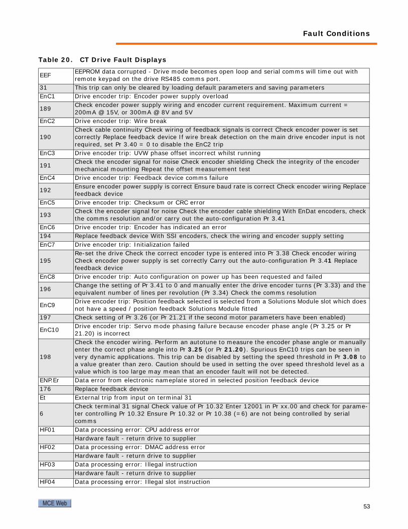
Fault Conditions
EEF EEPROM data corrupted - Drive mode becomes open loop and serial comms will time out with remote keypad on the drive RS485 comms port.
31 This trip can only be cleared by loading default parameters and saving parameters EnC1 Drive encoder trip: Encoder power supply overload
189 Check encoder power supply wiring and encoder current requirement. Maximum current = 200mA @ 15V, or 300mA @ 8V and 5V
EnC2 Drive encoder trip: Wire break
190 Check cable continuity Check wiring of feedback signals is correct Check encoder power is set correctly Replace feedback device If wire break detection on the main drive encoder input is not required, set Pr 3.40 = 0 to disable the EnC2 trip
EnC3 Drive encoder trip: UVW phase offset incorrect whilst running
191 Check the encoder signal for noise Check encoder shielding Check the integrity of the encoder mechanical mounting Repeat the offset measurement test
EnC4 Drive encoder trip: Feedback device comms failure
192 Ensure encoder power supply is correct Ensure baud rate is correct Check encoder wiring Replace feedback device
EnC5 Drive encoder trip: Checksum or CRC error
193 Check the encoder signal for noise Check the encoder cable shielding With EnDat encoders, check the comms resolution and/or carry out the auto-configuration Pr 3.41
EnC6 Drive encoder trip: Encoder has indicated an error 194 Replace feedback device With SSI encoders, check the wiring and encoder supply setting EnC7 Drive encoder trip: Initialization failed
195 Re-set the drive Check the correct encoder type is entered into Pr 3.38 Check encoder wiring Check encoder power supply is set correctly Carry out the auto-configuration Pr 3.41 Replace feedback device
EnC8 Drive encoder trip: Auto configuration on power up has been requested and failed
196 Change the setting of Pr 3.41 to 0 and manually enter the drive encoder turns (Pr 3.33) and the equivalent number of lines per revolution (Pr 3.34) Check the comms resolution
EnC9 Drive encoder trip: Position feedback selected is selected from a Solutions Module slot which does not have a speed / position feedback Solutions Module fitted
197 Check setting of Pr 3.26 (or Pr 21.21 if the second motor parameters have been enabled)
EnC10 Drive encoder trip: Servo mode phasing failure because encoder phase angle (Pr 3.25 or Pr 21.20) is incorrect
198
Check the encoder wiring. Perform an autotune to measure the encoder phase angle or manually enter the correct phase angle into Pr 3.25 (or Pr 21.20). Spurious EnC10 trips can be seen in very dynamic applications. This trip can be disabled by setting the speed threshold in Pr 3.08 to a value greater than zero. Caution should be used in setting the over speed threshold level as a value which is too large may mean that an encoder fault will not be detected.
ENP.Er Data error from electronic nameplate stored in selected position feedback device 176 Replace feedback device Et External trip from input on terminal 31
6 Check terminal 31 signal Check value of Pr 10.32 Enter 12001 in Pr xx.00 and check for parame-ter controlling Pr 10.32 Ensure Pr 10.32 or Pr 10.38 (=6) are not being controlled by serial comms
HF01 Data processing error: CPU address error Hardware fault - return drive to supplier
HF02 Data processing error: DMAC address error Hardware fault - return drive to supplier
HF03 Data processing error: Illegal instruction Hardware fault - return drive to supplier
HF04 Data processing error: Illegal slot instruction
Table 20. CT Drive Fault Displays
53
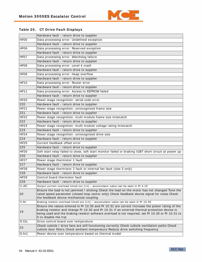
Motion 3000ES Escalator Control
Hardware fault - return drive to supplier HF05 Data processing error: Undefined exception
Hardware fault - return drive to supplier HF06 Data processing error: Reserved exception
Hardware fault - return drive to supplier HF07 Data processing error: Watchdog failure
Hardware fault - return drive to supplier HF08 Data processing error: Level 4 crash
Hardware fault - return drive to supplier HF09 Data processing error: Heap overflow
Hardware fault - return drive to supplier HF10 Data processing error: Router error
Hardware fault - return drive to supplier HF11 Data processing error: Access to EEPROM failed
Hardware fault - return drive to supplier HF20 Power stage recognition: serial code error 220 Hardware fault - return drive to supplier HF21 Power stage recognition: unrecognized frame size 221 Hardware fault - return drive to supplier HF22 Power stage recognition: multi module frame size mismatch 222 Hardware fault - return drive to supplier HF23 Power stage recognition: multi module voltage rating mismatch 223 Hardware fault - return drive to supplier HF24 Power stage recognition: unrecognized drive size 224 Hardware fault - return drive to supplier HF25 Current feedback offset error 225 Hardware fault - return drive to supplier HF26 Soft start relay failed to close, soft start monitor failed or braking IGBT short circuit at power up 226 Hardware fault - return drive to supplier HF27 Power stage thermistor 1 fault 227 Hardware fault - return drive to supplier HF28 Power stage thermistor 2 fault or internal fan fault (size 3 only) 228 Hardware fault - return drive to supplier HF29 Control board thermistor fault 229 Hardware fault - return drive to supplier It.AC Output current overload timed out (I2t) - accumulator value can be seen in Pr 4.19
20 Ensure the load is not jammed / sticking Check the load on the motor has not changed Tune the rated speed parameter (closed loop vector only) Check feedback device signal for noise Check the feedback device mechanical coupling
It.br Braking resistor overload timed out (I2t) – accumulator value can be seen in Pr 10.39
19
Ensure the values entered in Pr 10.30 and Pr 10.31 are correct Increase the power rating of the braking resistor and change Pr 10.30 and Pr 10.31 If an external thermal protection device is being used and the braking resistor software overload is not required, set Pr 10.30 or Pr 10.31 to 0 to disable the trip
O.CtL Drive control board over temperature
23 Check cubicle / drive fans are still functioning correctly Check cubicle ventilation paths Check cubicle door filters Check ambient temperature Reduce drive switching frequency
O.ht1 Power device over temperature based on thermal model
Table 20. CT Drive Fault Displays
54 Manual # 42-02-E001

Fault Conditions
21 Reduce drive switching frequency Reduce duty cycle Decrease acceleration / deceleration rates Reduce motor load
O.ht2 Heatsink over temperature
22
Check cooling fans, ventilation path, and filters.Increase ventilation.Decrease acceleration / deceleration rates.Reduce drive switching frequency.Reduce duty cycle.Reduce motor load.
Oht2.P Power module heatsink over temperature.
105
Check fans, ventilation paths, and filters.Increase ventilation.Decrease acceleration / deceleration rates.Reduce drive switching frequency.Reduce duty cycle.Reduce motor load.
O.ht3 Drive over temperature based on thermal model.
27
Drive will attempt to stop the motor before tripping. If the motor does not stop in 10s, the drive will trip.Check fans, ventilation paths, and filters.Increase ventilation.Decrease acceleration / deceleration rates.Reduce duty cycle.Reduce motor load.
Oht4.P Power module rectifier over temperature.
102
Check for supply imbalance.Check fans, ventilation paths, and filters.Increase ventilation.Decrease acceleration / deceleration rates.Reduce drive switching frequency.Reduce duty cycle.Reduce motor load.
OI.AC Instantaneous output over current detected: peak output current greater than 225%.
3
Acceleration / deceleration rate is too short.If seen during autotune, reduce voltage boost Pr 5.15. Check for short circuit on output cabling. Check integrity of motor insulation. Check feedback device wiring. Check feedback device mechanical coupling. Check feedback signals are free from noise.Is motor cable length within limits for that frame size? Reduce the values in speed loop gain parameters - Pr 3.10, Pr 3.11, and Pr 3.12 (closed loop vector)
Table 20. CT Drive Fault Displays
55

Motion 3000ES Escalator Control
OIAC.P Power module over current detected from the module output currents
104
Acceleration / deceleration rate is too short.If seen during autotune, reduce voltage boost Pr 5.15 Check for short circuit on output cabling Check integrity of motor insulation Check feedback device wiring Check feedback device mechanical coupling Check feedback signals are free from noiseIs motor cable length within limits for frame size? Reduce the values in speed loop gain parameters - Pr 3.10, Pr 3.11, and Pr 3.12 (closed loop vector)
OI.br Braking transistor over current detected: short circuit protection for the braking transistor acti-vated
4Check braking resistor wiringCheck braking resistor value is greater than or equal to the minimum resistance valueCheck braking resistor insulation
OIbr.P Power module braking IGBT over current
103Check braking resistor wiringCheck braking resistor value is greater than or equal to the minimum resistance valueCheck braking resistor insulation
OldC.P Power module over current detected from IGBT on state voltage monitoring
109 Vce IGBT protection activatedCheck motor and cable insulation
O.Ld1 Digital output overload: total current drawn from 24V supply and digital outputs exceeds 200mA26 Check total load on digital outputs (terminals 24, 25, 26) and +24V rail (terminal 22)OV DC bus voltage has exceeded the peak level or the maximum continuous level for 30 seconds
2
Increase deceleration ramp (Pr0.04)Decrease braking resistor value (staying above the minimum)Check nominal AC supply levelCheck for supply disturbances which could cause the DC bus to rise - voltage overshoot after supply recovery from a notch induced by DC drivesCheck motor insulationSee drive manual for additional
OV.P Power module over voltage
106
Increase deceleration ramp (Pr 0.04)Decrease braking resistor value (staying above minimum)Check nominal AC supply levelCheck for supply disturbancesCheck motor insulationSee drive manual for additional
O.SPd Motor speed has exceeded the over speed threshold
7Increase the over speed trip threshold in Pr 3.08 (closed loop only)Speed has exceeded 1.2 x P4r 106 or Pr 1.07 (open loop mode)Reduce the speed loop P gain (Pr 3.10) to reduce the speed overshoot (closed loop only)
PAd Keypad has been removed when the drive is receiving the speed reference from the keypad
34 Fit keypad and resetChange speed reference selector to select speed reference from another source
Ph AC voltage input phase loss or large supply imbalance detected
32
Ensure all three phases are present and balancedCheck input voltage levels are correct (at full load)Note: Load level must be between 50 and 100% for the drive to trip under phase loss conditions. The drive will attempt to stop the motor before this trip is initiated.
Table 20. CT Drive Fault Displays
56 Manual # 42-02-E001

Fault Conditions
Ph.P Power module phase loss detection
107 Ensure all three phases are present and balancedCheck input voltage levels are correct (at full load)
PS Internal power supply fault
5 Remove any Solutions Modules and reset Check integrity of interface ribbon cables and connec-tions (size 4,5,6 only) Hardware fault - return drive to supplier
PS.10V 10V user power supply current greater than 10mA 8 Check wiring to terminal 4 Reduce load on terminal 4 PS.24V 24V internal power supply overload
9
The total user load of the drive and Solutions Modules has exceeded the internal 24V power sup-ply limit. The user load consists of the drive digital outputs plus the SM-I/O Plus digital outputs, or the drive main encoder supply plus the SM-Universal Encoder Plus and SM-Encoder Plus encoder supply. • Reduce load and reset • Provide an external 24V >50W power supply • Remove any Solutions Modules and reset
rS Failure to measure resistance during autotune or when starting in open loop vector mode 0 or 3 33 Check motor power connection continuity SCL Drive RS485 serial comms loss to remote keypad
30 Refit the cable between the drive and keypad Check cable for damage Replace cable Replace key-pad
th Motor thermistor trip
24 Check motor temperature Check thermistor continuity Set Pr 7.15 = VOLt and reset the drive to disable this function
thS Motor thermistor short circuit
25 Check motor thermistor wiring Replace motor thermistor Set Pr 7.15 = VOLt and reset the drive to disable this function
tunE Autotune stopped before completion
18 The drive has tripped out during the autotune The red stop key has been pressed during the autotune The secure disable signal (terminal 31) was active during the autotune procedure
tunE1 The position feedback did not change or required speed could not be reached during the inertia test (see Pr 5.12)
11 Ensure the motor is free to turn i.e. brake was released Check encoder coupling to motor
tunE2 Position feedback direction incorrect or motor could not be stopped during the inertia test (see Pr 5.12)
12 Check motor cable wiring is correct Check feedback device wiring is correct Swap any two motor phases (closed loop vector only)
tunE3 Drive encoder commutation signals connected incorrectly or measured inertia out of range (see Pr 5.12)
13 Check motor cable wiring is correct Check feedback device U,V and W commutation signal wiring is correct
tunE4 Drive encoder U commutation signal fail during an autotune 14 Check feedback device U phase commutation wires continuity Replace encoder tunE5 Drive encoder V commutation signal fail during an autotune 15 Check feedback device V phase commutation wires continuity Replace encoder tunE6 Drive encoder W commutation signal fail during an autotune 16 Check feedback device W phase commutation wires continuity Replace encoder tunE7 Motor number of poles set incorrectly
17 Check lines per revolution for feedback device Check the number of poles in Pr 5.11 is set cor-rectly
Table 20. CT Drive Fault Displays
57

Motion 3000ES Escalator Control
Uflt Multi module drive: Unidentified fault
171 Check all interconnecting cables between power modules Ensure cables are routed away from electrical noise sources
UP div0 Onboard PLC program attempted divide by zero 90 Check program
UP OFL Onboard PLC program variables and function block calls using more than the allowed RAM space (stack overflow)
95 Check program UP ovr Onboard PLC program attempted out of range parameter write 94 Check program UP PAr Onboard PLC program attempted access to a non-existent parameter 91 Check program UP ro Onboard PLC program attempted write to a read-only parameter 92 Check program UP So Onboard PLC program attempted read of a write-only parameter 93 Check program UP udf Onboard PLC program un-defined trip 97 Check program UP uSEr Onboard PLC program requested a trip 96 Check program UV DC bus under voltage threshold reached
1 Check AC supply voltage level Drive voltage rating (Vac) Under voltage threshold (Vdc)
Table 20. CT Drive Fault Displays
58 Manual # 42-02-E001

Fault Conditions
KEB Drive Faults
Note
The drive faults listed here are current as of publication of these tables. If you believe that a description is not accurate, please consult the manufacturer manual shipped with the drive.
Table 21. KEB Drive Error Displays
Display Description Cause
E. UPUnder voltage. DC bus voltage below per-missible value; input single-phasing; phase imbalance greater than 2%.
• Input voltage low or unstable.• Input wiring incorrect.• Isolation transformer too small.• Isolation transformer connected wrong.• One phase of input missing.• Phase imbalance over 2%.
E. OP
Over voltage. DC bus voltage above per-missible value during motor regenerative operation or because of line side voltage spikes.
• Input voltage too high; install step down tx.• Voltage spikes on line; install line choke.• Brake resistor connection incorrect.• Brake resistor resistance too large.• Inverter poorly grounded.
E. OC Peak output current exceeded or ground fault.
• Short circuit on motor leads.• Ground fault on motor leads.• Motor contactor damaged or burned.• Inverter poorly grounded.• Incorrect motor data (LF10-LF19).• Shorted output transistor.
E. OL Time dependent overload. See KEB man-ual.
• Motor wired incorrectly.• Motor data wrong (check motor current).• Inverter too small.• High mechanical load.
E.OL2 Time dependent overload at low speed. See KEB manual.
• Motor stand still current too high.• Incorrect motor data.• Inverter too small.• High mechanical load.• Motor wired incorrectly.
E.nOL Cool down phase completed (after an E.OL or E.OL2 error). • E.OL or E. OL2 errors can now be reset.
E. OH Inverter overheat. Heat sink temperature above permissible limit.
• Insufficient cooling.• Ambient temperature too high.• Cooling fan clogged.
E.dOH Motor over temp. External motor temp switch tripped.
• Terminals T1/T2 resistance over 1650 ohms.• Motor temp sensor overheat.• Factory T1/T2 jumper missing.
E.nOH Overtemp cooled down. Over temp error may now be reset. • Temperature now at safe level.
E. 0S Over speed. • Speed over 110% of LF.20.• Verify LF.10 - LF.19, LF.27.• Encoder cable noise.
59

Motion 3000ES Escalator Control
E.LSFDC Bus charging error. Occurs for a short time during drive power up but clears auto-matically if no real error exists.
• Input voltage wrong or too low.• High supply line resistance.• Incorrect brake resistor connection.• Braking transistor not functioning.• Inverter failure.
E.EnC Encoder failure. • Encoder connection problem.• Encoder channels reversed.
E.EnC 1 Encoder signal loss; wrong rotation direc-tion or too much drag.
• Encoder signal missing.• Check encoder connections and signals.
E.EnCC Encoder communication error. Serial com-munication problem with encoder.
• See parameters 2.LF.26.• Clear through 0.LF.26 when ready.
E.PuC 1 Power unit code. Power stage not identified during initialization. • Replace drive.
E.PuCH Power unit code changed. Typically experi-enced when changing control cards.
• Unit will automatically configure for new power stage and clear error.• Drive maintains history for reference.• Clear through parameter US.27.
E.br
Error current check. Before each run, drive sends current to each motor phase to ver-ify. Then applies magnetizing current and monitors.
• One or more motor leads disconnected.• Motor contactor timing incorrect.• Motor contactor damaged or burnt.• Motor windings damaged.• Drive unable to generate acceptable current levels.• May be bypassed through US.25 = 1.
E.hybC Encoder card changed.• Error will clear automatically.• New feedback card will be recognized.• Unit maintains history.
E.hyb Encoder card invalid. • Damaged encoder card.
E.OH2 Electronic motor overload.• Motor current exceeds LF.9 or LF.12.• Mechanical load excessive.• Check motor data LF.10 - LF.19.
E.buS Serial communication between keypad and drive lost. (Bypass through US.29.)
• Error will clear when communication is restored.• If not, remove keypad, cycle drive power, verify red pilot LED on steady, reinstall key-pad.• Check KEB manual.
bbLPrecedes most faults. Also occurs if the drive enable is turned off while the car is running.
• Indicates output transistors have been safely shut off and are being blocked from fur-ther operation.
Table 21. KEB Drive Error Displays
Display Description Cause
60 Manual # 42-02-E001

Brake Module
Brake ModuleIn a typical escalator machine brake control circuit, a fixed voltage is abruptly applied or removed to control the position of the brake. There is no control of the rate at which the brake moves — the command is simply on, or off. Control voltages are provided to pick, hold, and drop the brake.
A brake control module, used for permanent magnet, disk brake applications, allows the level of the control voltage to be adjusted. Modulated voltages provide control over the entire range of brake movement. The module provides the ability to control the rate at which the brake descends onto the braking surface. With this ability, brake control can be more subtle resulting in a smoother ride under all motion conditions in which the brake plays a part, saving energy, and reducing brake coil temperatures.
The MCE brake module can be controlled by discrete inputs or through a CAN interface. Dis-crete control provides compatibility with MCE legacy controls. If a machine has dual indepen-dent brakes with one being used as an unintended motion emergency brake and the other as the standard machine brake, two modules are required.
Figure 8. Motion Brake Module
Logic TC-FCL
Heat sink
Inverter power supply TC-FCP
Logic power supply TC-LPS
61

Motion 3000ES Escalator Control
ConfigurationThe top board, TC-FCL, provides the controls to configure the module for job requirements. Such configuration is completed at the factory when the module is shipped installed in a con-troller. If the module is a modification to an existing control, check this instruction for proper settings. If you are replacing an existing module, set up the new module to match.
Figure 9. Configuration
Switches and Jumpers
Table 22. SW1, Manual Bypass
2 1 Description
Off Off Manual brake pick enabled (will cause Main IGBT stuck open fault to be indicated until the brake contactor is picked to allow power to the brake module). In this mode, a manual brake pick switch connected between BRBP1 and BRBP3 will energize the brake coil connected between BRBP2 and BRBP4 and immediately lift the brake regardless of the status of the escalator control-ler.
Off On UnusedOn Off UnusedOn On Unused
62 Manual # 42-02-E001

Brake Module
The four switches of DIP switch SW3 function as two independent pairs. Switches 4 and 3 enable various software features. Switches 2 and 1 set the ID for the module. The ID identifies the module to the controller allowing it to be addressed and controlled independently of any other modules used (up to three).
Reset Switch The reset switch, RST, resets the logic board processor.
Jumper JP1 JP1 enables/disables the CAN termination resistor.
• A position: Terminates the CAN connection on the board.
• B position: Leaves the CAN termination open on the board (Normal position for this board).
ON LEDThe ON LED next to the Reset switch is on solidly when the module is powered and functioning properly. The ON LED will blink if a fault condition is detected. Under fault conditions, the LED will blink a number of times, go dark for a period of time, and then repeat. The number of blinks indicates the fault detected..
Table 23. SW3 Module ID and Software Features
4 3 2 1 Description
Off Off Brake module, ID=1 Primary brake module addressOff On Brake module, ID=2 Secondary brake module address where module 1 controls the first
brake coil and module 2 controls a second brake coil on the same machine.On Off Brake module, ID=3 Emergency brake module addressOn On Module, ID=4 Future
Off Off Standard modeOff On Escalator mode.On Off Enables software update from EEPROM chip inserted in socket U21On On unused
Table 24. LED Fault Indication
Blinks Fault Description Reset
1 Load over current If load current goes above 20A during the first 5 sec-onds of operation or above 15A for 5 seconds during operation, over current will be reported and current will be limited to 15A.
Current reduction
2 Load over voltage If load voltage goes above 310VDC for more than 5 seconds, over voltage condition will be reported through FLT output and voltage will be limited to 310V.
Voltage reduction
3 Aux IGBT stuck open If the brake is in pick, hold, or relevel mode and the Aux IGBT monitoring circuit returns a high signal for 100mS or more, the Aux IGBT stuck closed fault will occur.
Discrete: Proces-sor reset.CAN: Auto reset after 8 seconds.
63
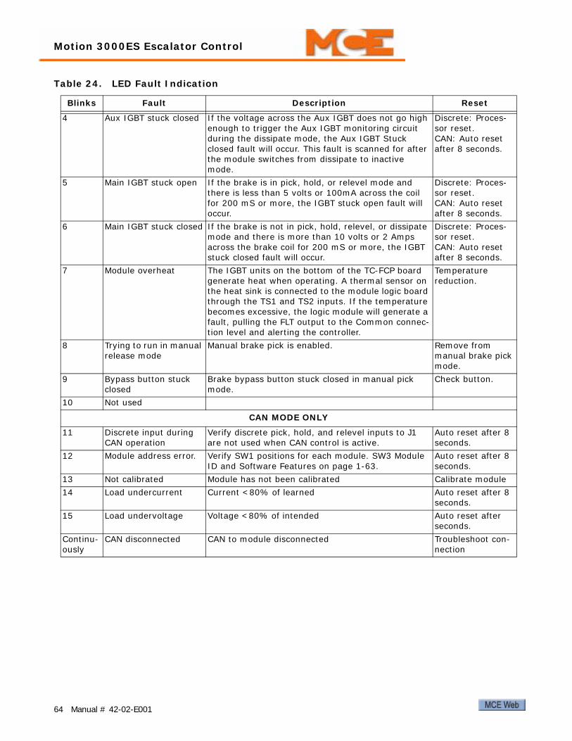
Motion 3000ES Escalator Control
4 Aux IGBT stuck closed If the voltage across the Aux IGBT does not go high enough to trigger the Aux IGBT monitoring circuit during the dissipate mode, the Aux IGBT Stuck closed fault will occur. This fault is scanned for after the module switches from dissipate to inactive mode.
Discrete: Proces-sor reset.CAN: Auto reset after 8 seconds.
5 Main IGBT stuck open If the brake is in pick, hold, or relevel mode and there is less than 5 volts or 100mA across the coil for 200 mS or more, the IGBT stuck open fault will occur.
Discrete: Proces-sor reset.CAN: Auto reset after 8 seconds.
6 Main IGBT stuck closed If the brake is not in pick, hold, relevel, or dissipate mode and there is more than 10 volts or 2 Amps across the brake coil for 200 mS or more, the IGBT stuck closed fault will occur.
Discrete: Proces-sor reset.CAN: Auto reset after 8 seconds.
7 Module overheat The IGBT units on the bottom of the TC-FCP board generate heat when operating. A thermal sensor on the heat sink is connected to the module logic board through the TS1 and TS2 inputs. If the temperature becomes excessive, the logic module will generate a fault, pulling the FLT output to the Common connec-tion level and alerting the controller.
Temperature reduction.
8 Trying to run in manual release mode
Manual brake pick is enabled. Remove from manual brake pick mode.
9 Bypass button stuck closed
Brake bypass button stuck closed in manual pick mode.
Check button.
10 Not used
CAN MODE ONLY
11 Discrete input during CAN operation
Verify discrete pick, hold, and relevel inputs to J1 are not used when CAN control is active.
Auto reset after 8 seconds.
12 Module address error. Verify SW1 positions for each module. SW3 Module ID and Software Features on page 1-63.
Auto reset after 8 seconds.
13 Not calibrated Module has not been calibrated Calibrate module14 Load undercurrent Current <80% of learned Auto reset after 8
seconds.15 Load undervoltage Voltage <80% of intended Auto reset after
seconds.Continu-ously
CAN disconnected CAN to module disconnected Troubleshoot con-nection
Table 24. LED Fault Indication
Blinks Fault Description Reset
64 Manual # 42-02-E001

Brake Module
Module Connectors Per Board
Top Board, TC-FCLThis section provides information about user-accessible module connections.
J4, J5 J4 is a modular, CAN connector for serial module control. (See preceding informa-tion about termination enabling jumper JP1.) J5 provides auxiliary connections that can be used to directly lift the machine brake, regardless of controller status.
The level of the pick voltage is adjusted using potentiometer R67. The maximum pick voltage range is determined by input voltage to the module and whether the input connection is single phase, FCL1/FCL2, or three phase, FCL1/FCL2/FCL3.
J3 J3 provides control signals to the TC-FCP board and accepts feedback voltages from the TC-FCP board.
J6 J6 accepts DC power voltages from the logic power supply board (TC-LPS).
Middle Board, TC-LPS1 and 2 bus power connections from the controller are connected to TC-LPS connector J1. As viewed from the front of the connector, pinout is:
This board provides DC power to the logic board through connector J2.
Table 25. J1 Pin Assignment
Pin Function
PICK Discrete Pick control input from controller (V AC/DC)HOLD Discrete Hold control input from controller (V AC/DC)RELEV Discrete Relevel control input from controller (V AC/DC)FLT Overload fault outputCOM Common connection for PICK, HOLD, RELEV, FLT1 1 Bus (common) from escalator controller2 2 Bus (120VAC) from escalator controllerTS2 Thermal switch input from sensor on module heat sinkTS1 Thermal switch input from sensor on module heat sink
Table 26. J5 Auxiliary Brake Connections
Pin Function
BRBP1 With BRBP3, connects to auxiliary brake pick switchBRBP2 With BRBP4, energizes brake coil when activeBRBP3 With BRBP1, connects to auxiliary brake pick switchBRBP4 With BRBP2, energizes brake coil when active
1122
65

Motion 3000ES Escalator Control
Bottom Board, TC-FCPThe FCP board transforms AC input power (single or three phase) into the DC output voltage required to control the brake. The in-line connectors on the board are sized to handle higher voltage and current.
Figure 10. External Filtering
Table 27. In-Line Connectors Pin Assignment
Pin Function
J2, SN1 With SN2, connection point for external filter provided with unitJ2, SN2 With SN1, connection point for external filter provided with unitJ2, SN3 With J3, SN4, connection point for user-provided external filterJ3, SN4 With J2, SN3, connection point for user-provided external filterJ3, FCO- With FCO+, provides power to energize brake coil under normal logic conditionsJ3, FCO+ With FCO-, provides power to energize brake coil under normal logic conditionsJ5, DT1 Factory Only. Production testing.J5, DT2 Factory Only. Production testing.J5, FCL1 AC input, with J6, FCL2 for single-phase use or J6, FCL2/FCL3 for three-phase useJ6, FCL2 AC input, with J5, FCL1 for single-phase use or J5, FCL1/J6 FCL3 for three-phase useJ6, FCL3 AC input, with J5, FCL1 and J6, FCL2 for three-phase use.
Module
FCO+
SN4
SN2
SN1
SN3
FCO-
Filter
OptionalFilter
Brake Coil
66 Manual # 42-02-E001


Motion 3000ES Escalator Control
AdjustmentTypically, the module will have been pre-installed and connected at the factory. If you are replacing an existing module, mount this module in the same location and follow the controller job prints to make electrical connections.
Note
This module may be used with TC-FCL board DIP switch 3, rockers 3 and 4 set to standard or escalator mode. See “SW3 Module ID and Software Features” on page 63 . If in standard mode, adjust as below. If in escalator mode, see “Escalator Mode” on page 69.
Trim pots and Function (Discrete Control Only)Potentiometer settings are used primarily when the module is being controlled through the dis-crete connections.
• R67, Brake Pick Voltage (maximum output to lift brake), LED lights• R68, Brake Hold Voltage (percentage of Pick Voltage), LED lights• R69, Brake Relevel Voltage (percentage of Pick Voltage), LED lights• R70, Brake Drop Rate (clockwise = faster)• R71, Brake Pick Rate (clockwise = faster)
Setup for Adjustment1. Disconnect power to the controller.2. Discrete control only. Rotate trim pots R67, 68, and 69 counter-clockwise to locate the
begin stop, then clockwise to locate the end stop. Then set to the approximate center position.
3. Connect Brake outputs FCO+/FCO- and BRBP2/BRBP4 (if used) as shown in your job drawings. These connections are probably made from the module to a panel-mount con-nector and from the panel-mount connector to the brake.
4. Connect the brake filter across SN1/SN2 as shown on the job prints. Connect the input 3- or single-phase power as shown in the job prints.
5. Connect control inputs from escalator controller as shown in your job prints (CAN or Discrete control).
6. Connect a volt meter across the brake coil.
Discrete Control AdjustmentCheck that there is no CAN connection to the brake module. This procedure is for discrete volt-ages control.
1. Apply power to the controller. Place the escalator on Inspection operation and pick a direction.
2. With the brake picked, adjust R67 to attain the brake manufacturer pick voltage. Verify that the brake picks cleanly.
3. After the brake settles to hold position, adjust R68 to attain manufacturer hold voltage. Verify that the brake is not dragging.
4. Disconnect power from the controller.
68 Manual # 42-02-E001
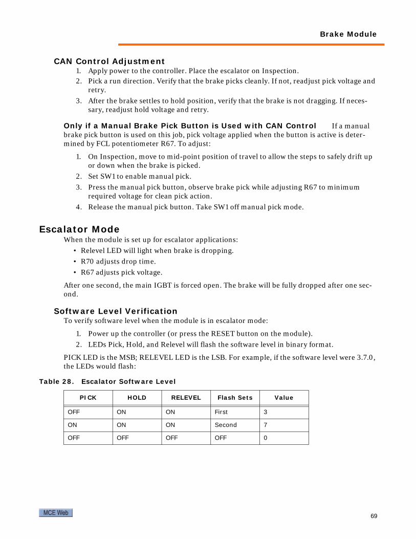
Brake Module
CAN Control Adjustment1. Apply power to the controller. Place the escalator on Inspection.2. Pick a run direction. Verify that the brake picks cleanly. If not, readjust pick voltage and
retry.
3. After the brake settles to hold position, verify that the brake is not dragging. If neces-sary, readjust hold voltage and retry.
Only if a Manual Brake Pick Button is Used with CAN Control If a manual brake pick button is used on this job, pick voltage applied when the button is active is deter-mined by FCL potentiometer R67. To adjust:
1. On Inspection, move to mid-point position of travel to allow the steps to safely drift up or down when the brake is picked.
2. Set SW1 to enable manual pick.
3. Press the manual pick button, observe brake pick while adjusting R67 to minimum required voltage for clean pick action.
4. Release the manual pick button. Take SW1 off manual pick mode.
Escalator ModeWhen the module is set up for escalator applications:
• Relevel LED will light when brake is dropping.
• R70 adjusts drop time.
• R67 adjusts pick voltage.
After one second, the main IGBT is forced open. The brake will be fully dropped after one sec-ond.
Software Level VerificationTo verify software level when the module is in escalator mode:
1. Power up the controller (or press the RESET button on the module).
2. LEDs Pick, Hold, and Relevel will flash the software level in binary format.
PICK LED is the MSB; RELEVEL LED is the LSB. For example, if the software level were 3.7.0, the LEDs would flash:
Table 28. Escalator Software Level
PICK HOLD RELEVEL Flash Sets Value
OFF ON ON First 3
ON ON ON Second 7
OFF OFF OFF OFF 0
69

Motion 3000ES Escalator Control
Typical mBrake InstallationTypical mBrake connection is illustrated below.
Figure 12. mBrake Connection
70 Manual # 42-02-E001

AAC wiring 4Auxiliary Brake 15
BBottom/top display board jumper 21Brake delay 30Brake module
LED fault indication 63Brake pick 26Brake resistance 15
CCAN bus termination 21Check for shorts 3Checking the Motor 14Clear fault history 34Code compliance 1Connector descriptions 19Construction Mode 7
Overview 24Controller faults 48CT drive parameter editing 10CT Emerson drive 9
DDisplay board J1 21DOWN button 6Drive Faults
bbL 60C.Acc 52C.Chg 52C.Cpr 52C.dat 52C.Err 52C.Full 52C.Optn 52C.rdo 52C.rtg 52C.Typ 52CL.bit 52CL2 52CL3 52dESt 52E. 0S 59E. OC 59E. OH 59E. OL 59E. OP 59E.br 60E.buS 60E.dOH 59E.EnC 60E.EnC 1 60E.EnCC 60E.hyb 60E.hybC 60E.LSF 60E.nOH 59
E.nOL 59E.OH2 60E.OL2 59E.PuC 1 60E.PuCH 60EEF 53EnC1 53EnC10 53EnC2 53EnC3 53EnC4 53EnC5 53EnC6 53EnC7 53EnC8 53EnC9 53ENP.Er 53Et 53HF01 53HF02 53HF03 53HF04 53HF05 54HF06 54HF07 54HF08 54HF09 54HF10 54HF11 54HF20 54HF21 54HF22 54HF23 54HF24 54HF25 54HF26 54HF27 54HF28 54HF29 54It.AC 54It.br 54O.CtL 54O.ht1 54O.ht2 55O.ht3 55O.Ld1 56O.SPd 56Oht2.P 55Oht4.P 55OI.AC 55OI.br 56OIAC.P 56OIbr.P 56OldC.P 56OV 56OV.P 56PAd 56Ph 56Ph.P 57PS 57
Index-1

PS.10V 57PS.24V 57rS 57SCL 57th 57thS 57tunE 57tunE1 57tunE2 57tunE3 57tunE4 57tunE5 57tunE6 57tunE7 57Uflt 58UP div0 58UP OFL 58UP ovr 58UP PAr 58UP ro 58UP So 58UP udf 58UP uSEr 58UV 58
Drive faults 52Drive mode 32Drive Parameters
Acceleration rate 39Auto Tuning Mode Select 40Belt Creep Speed 39Belt Speed-FPM 40Brake Apply Frequency 39Brake controller enable 39Catch a Spinning Motor 40Current Loop Ki Gain 40Current Loop Kp Gain 40Deceleration rate 39Drive Software Version 40Drive Voltage Rating 40Dynamic Volts/Hz 39Full power braking time 39Low Frequency Voltage Boost 39Lower Brake Current Threshold 39Maximum Frequency 39Maximum Heavy Duty Rating 40Maximum Switching Frequency 40Minimum Frequency 39Motor Rated Current 40Motor Rated Frequency 40Motor RPM Readout 39Number of motor poles 40Output Frequency 39Parameter displayed at power-up 40Post brake release delay 39Rated load rpm / rated speed 40Rated Motor Power Factor 40Rated Motor Voltage 40Reference Selector 39Relay source 39Revision Number 39
S ramp enable 39Security Status 40Serial Comms Address 40Serial Comms Mode 40Serial Comms Rate 40Smart/Cloning Card 39Symmetrical Current Limit 39T28 digital input 5 destination 39T29 digital input 6 destination 39User Drive Mode of Operation 40User Security Code 40Voltage mode select 39
EEC-MCB connectors 19EC-SCB connectors 21ESC button 6Escalator learn operation 28
FF5-07 7, 24Fault reset
Controller 6Faults 48
GGrounding 3
HHandrail speed monitoring 16, 18
IInspection control connections 26
KKEB drive setting 11KEB F5 drive 11
LLearn operation 28
MMotor Insulation Testing 14
OOK 6
PParameter setting example 7Passcode 34PI board position jumper 21
Index-2 Manual # 42-02-E001
RRemote Inspection Control 26Reset controller parameters 34RFI 3RFI/EMI 14Run learn operation 28
SSafety string 15, 28Self-learn 33Shorts 3Speed mode 32Step sensors 16Step speed monitoring 16
TTop/Bottom display board jumper 21
UUP button 6
VVerifying Main Line Power 4
WWiring the Brake 15Wiring the Motor 14
Index-3