user guide of plan module v2.1.0
TRANSCRIPT

1
User Guide of Plan Module
Quick Look
1 Introduction
Plan Module is an automatic mapping module in DepthInsight®, and it is associated with 3D
Modeling Software. 3D Modeling Software can launch Plan Module and provide original
vector data of 3D horizons to it. Based on the original vector data, Plan Module can
automatically produce and display 2D geological plans. It's able to check the model quality by
opening plans in the process of modeling at any time.
As an automatic mapping module, Plan Module has the following features: automatic,
efficient, vector data, editable, etc.
1.1 Data Source
① Other modeling modules provide original data to Plan Module, which include 3D vector
data of horizon, such as grids and attributes..
② Plan Module also can import existing structural plan in BMP or DXF format as reference
background, and it has functions to draw contour lines and fault polygons manually. With this
new data, Plan Module can produce a new plan.
③ Plan Module can load well data, including well head, well path, well type, well tops, and so
on, from specified database.
1.2 Module Function
Plan Module can:
① Convert 3D vector data of horizons to 2D plan and display it;
② Distill structure contours and fault polygons from the 3D vector data of horizon;

2
③ Distill attribute contours from the grids and attributes in the vector data of horizon, and
display those contours in gradient;
④ Load and display well data from specified Database;
⑤ Simply edit data in plan map.
1.3 Export
Plan not only could be saved in DI format with suffix '.pla', but could also be exported as
follows:
CGM format;
Double Fox format;
BMP bitmap;
2 Module Relationships
Plan acts as a service module, and many modeling modules in DepthInsight® could launch Plan
Module and send vector data to it. Every function named like 'Open xx plan' in DepthInsight®
could start Plan Module to display a plan.
The relationships between Plan Module and other modules are as shown below:
3
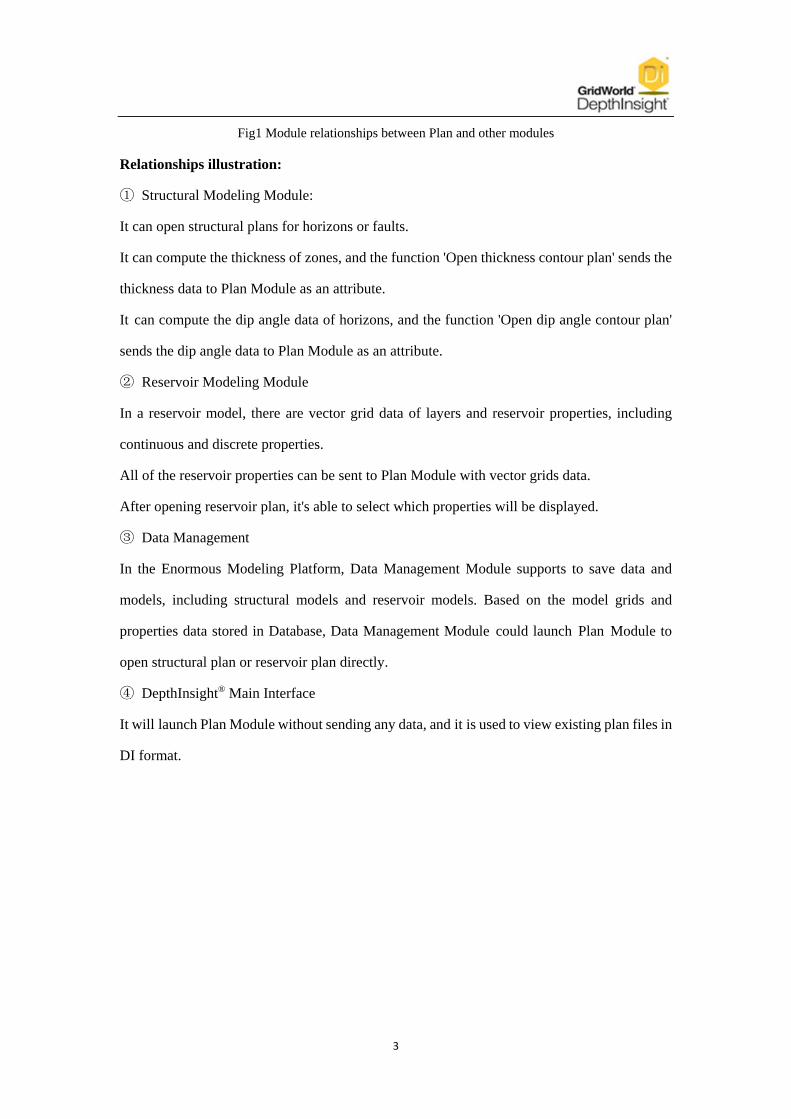
Fig1 Module relationships between Plan and other modules
Relationships illustration:
① Structural Modeling Module:
It can open structural plans for horizons or faults.
It can compute the thickness of zones, and the function 'Open thickness contour plan' sends the
thickness data to Plan Module as an attribute.
It can compute the dip angle data of horizons, and the function 'Open dip angle contour plan'
sends the dip angle data to Plan Module as an attribute.
② Reservoir Modeling Module
In a reservoir model, there are vector grid data of layers and reservoir properties, including
continuous and discrete properties.
All of the reservoir properties can be sent to Plan Module with vector grids data.
After opening reservoir plan, it's able to select which properties will be displayed.
③ Data Management
In the Enormous Modeling Platform, Data Management Module supports to save data and
models, including structural models and reservoir models. Based on the model grids and
properties data stored in Database, Data Management Module could launch Plan Module to
open structural plan or reservoir plan directly.
④ DepthInsight® Main Interface
It will launch Plan Module without sending any data, and it is used to view existing plan files in
DI format.

4
Special topic
1 Structural plan
1.1 The methods of opening structural plan (three methods)
a、In structure module, select the objective horizon under the node of Horizons, start
right-click menu, choose Open structural plan. In the pop-up dialog box, set the name, step
length and scale of the plan (Fig.a); or in the opened plan, set the parameters such as scale and
step length in the property bar (Fig.b, Fig.c).
(a)
(b) (c)
b、Startup structural plan in the main interface of DI, seeing that opened plan is empty. Right
click the node of Plan in the tree window, then select Add plan. According to the saving path,
add the plan which has been saved before, as shown in the figure below:

5
c、Search for the symbol of Plan.exe in the software, open it by double click, then right click
the node of Plan in the tree window and elect Add plan. According to the saving path, add
the plan which has been saved before, as shown in the figure below:
1.2 Extract well
After opening structural plan, the attribute of wells, well tops, discrete well logs can all be
extracted to the plan on the node of wells in the tree window and the attribute parameters
about wells can be set in the property bar. We can also modify the well types and save them to
the database, the following to introduce some of the important functions respectively:
a、Extract
After executing Extract(Fig.a), set the information such as work area、seismic survey、well

6
type which match the plan in the pop-up dialog box (Fig.b). Click OK, and the wells can be
extracted into the view. Set the size of the wellhead symbol and the well name in the property
bar. The results are shown in Fig.c below:
(a) (b) (c)
b、Extract well logs
Before executing Extract well log, calculate the thickness or the dip angle of objective
horizon, then open thickness contour plan or open dip angle contour plan extract well logs
after extracting wells (Fig.a);set the display parameters of well attribute in the property bar
(Fig.b);the results are shown in Fig.c below:
(a) (b) (c)
Note:The function of Extract well logs can be executed on the condition that the stratum
attribute information, such as thickness and dip angle, are culculated. Besides only discrete
well logs can be extracted and coarsening.
c、Edit well type
After selecting Edit well type, move the mouse slipping over wellhead in the view window,
then the wellhead will be highlighted (Fig.a);click the highlighted wellhead, modify the type
of the selected well in property bar (Fig.b); after selection, the symbol of well type will
change accordingly (Fig.c) :

7
(a) (b) (c)
d、Save well type information
This function is to save well types that have been edited into the database, which facilitates
subsequent establishing the plan of the horizon or other reconstruction plan, or extracting the
well or screening. Execute the command in the pop-up dialog box, select the database in the
corresponding project name. After it is successfully saved, information bar will prompt.
Specific operations are as shown in the figure below:
The part of extracting wells will be detailed interpreted in the video.
1.3 Edit structural plan
The structural map can be cut by right clicking. Parameters such as gradient ramp can be set
via property bar. This is relatively simple, no more specific details here.
1.4 Edit fault lines
After opening structural plan, sometimes we need to edit the Fault lines, including Fault
lines' shape, type, color, width, downthrow identification, properties and so on. These
operations can be realized by right clicking and operation on the property bar. Here are
several important functions below:
a、Set upthrow or downthrow of fault

8
After executing the command (Fig.a), select a fault line in the view, the fault line will be
highlighted (Fig.b). In the property bar on the right, set the fault type (upthrow side or not)
which the fault line belongs to. (Fig.c);
(a) (b) (c)
b、Edit dip symbols
After executing the command, select a fault line in the view (Fig.a), the fault line will be
highlighted (Fig.b). Select downthrow identification symbols with the mouse, we can edit
them such as moving, deleting, and inversing (Fig.c);
(a) (b) (c)
c、Export fault polygon
After executing the command, the faults in the plan can be exported into the outer polygon
file in the form of fault polygon. In the later modeling, we can import fault polygon files on
the node of Intersections under the node of Horizons in structure module. The chart below
is part of exported fault polygon file:
Note:Every time we execute the function of right-click menu, there will be a corresponding
message in the information bar, which suggests a variety of methods to edit operation.

9
Beginners tend to ignore the information in the information bar,so beginners consequently
cannot operate. Therefore when performing a function, please pay more attention to the
information bar.
1.5 Edit erosion lines
In the opened structural plan, sometimes we need to edit Erosion lines, including erosion
lines' shape, color, width, type and the dip identification symbols, etc. These operations can be
set by right clicking menu or via property bar on the right. Such as shown in the figure below:
1.6 Structure contour
In the opened structural plan, sometimes we need to edit Structure contour, including setting
the color, width, line type, the size of the text, generating parameter settings and so on. These
operations can be realised by setting parameters in the property bar on the right (right-down
figure). Besides, right-click menu also have the functions of editing contour lines and
artificial drawing contour lines, as shown in left-down figure. Here are a few important
functions about Structure contour below:

10
a、Automatic update
The default setting of "Automatic update" located on the property bar on the node of
Structure contour is not ticked, because it will take a large number of calculation when
generating contour lines, so when we switch mouse to the node of Structure contour,
Automatic update will shift to manual update. The condition will not be recorded, currently
effective only.
b、Several important parameters in the property bar are explained as below:
Starting position of cardinal line:The parameter value imported represents an attribute value,
then the software will assign the contour line which has the same value to the cardinal lines,
thus making it easy for users to customize the cardinal lines.
Step length(m): Attribute difference between two adjacent contour lines.
Smooth step length(m): The greater the value, the more smooth the contour line is.
1.7 Attribute
In the structure plan, the property bar of Attributes is set grey, because the pure structure
plan does not have attribute value; while in thickness contour plan or dip angle contour plan
this term can be set because the plan already has its own attributes, such as thickness and dip
angle. About thickness contour plan and dip angle contour plan, we will proceed in later
chapters.

11
1.8 Scale
By right clicking menu and setting parameters in the property bar on the node of Scale, you
can change the information about scale such as size and color, as shown in the figure below,
here no longer expatiatory.
1.9 Kilometer grids
The node of Kilometer grids contains two child node which are the Gridlines and
Responsibility column, we can respectively set the specific parameters in the property bar
including the Gridlines' color, line width, etc; date, source information, scale of
Responsibility column, such as shown in the figure below, no longer expatiatory here.
1.10 Compass
By right clicking menu on the node of Compass and setting parameters in the property bar,
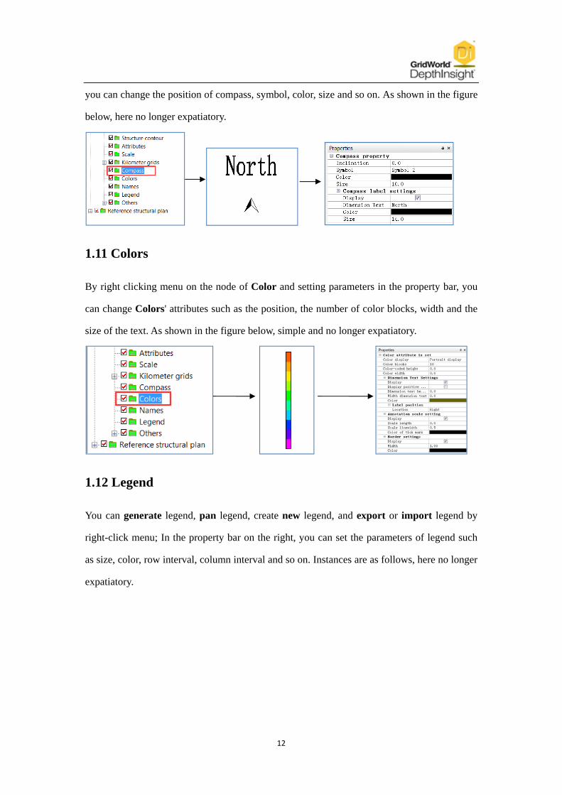
12
you can change the position of compass, symbol, color, size and so on. As shown in the figure
below, here no longer expatiatory.
1.11 Colors
By right clicking menu on the node of Color and setting parameters in the property bar, you
can change Colors' attributes such as the position, the number of color blocks, width and the
size of the text. As shown in the figure below, simple and no longer expatiatory.
1.12 Legend
You can generate legend, pan legend, create new legend, and export or import legend by
right-click menu; In the property bar on the right, you can set the parameters of legend such
as size, color, row interval, column interval and so on. Instances are as follows, here no longer
expatiatory.

13
1.13 The creation and edition of points、polyline、curve、area and text
You can create point, polyline, curve, area, text and other item on the node of Others, as
shown in the figure below. After creation, they will be automatically saved to the
corresponding node below Others, and they can be edited by right clicking menu or setting
parameters in property bar. For example, after we created point, it will be saved to the node of
Point set automatically. When you want to edit the point, choose it under the node of Point
set, starting right-click menu or setting parameters in property bar. The function of the node in
plan is the same with profile.
1.14 Reference structural plan
We can import external BMP format reference structure map or DXF format reference map
into the structure plan.

14
1.15 Save and export structural plan
When finishing editing plan in DI, we need to save it or export it into other format of
structural plan.
a、Save
After executing Save, a save path dialog box will pop up, we save the plan. The format of the
plan which is saved in this way is plan. This format is supported by DepthInsight software, so
it can be opened again by DepthInsight software for editing and other operations.
b、Export CGM format plan
After executing Export CGM format plan, the format of plan can be saved and converted to
CGM format, the plan can be edited further more. The CGM format structural plan below is
opened in SDI editor software :

15
c、Export DoubleFox format plan
After we executed Export DoubleFox format plan, the format of plan can be saved and
converted to DFD format, so that the plan can be edited further more in DoubleFox software
.
d、Print to image
After Print to the image is executed, structural plan will be converted into BMP bitmap file.
We can set the parameters such as the print quality and the paper size in the pop-up dialog
box. Instances are as follows:
2 Local structural plan
2.1 The method of opening local structural plan
In structure module, select the target horizon under the node of Horizons, right click it and
select Open local structural plan (Fig.a). Then draw a rectangular boundary on the plan,
start with left click and end with double right click (Fig.b). In the pop-up dialog, we can
modify the name, step length, and the scale of the plan (Fig.c),and we can also set the step

16
length and the scale in the opened plan in property bar on the right (Fig.d).
(a) (b)
(c) (d)
2.2 Else
The only difference between local structural plan and structural plan lies in the open way
and the range of the area. After the local structural plan is opened, editing is exactly the same
with structure contour plan. Here no longer expatiatory.
3 Thickness contour plan
3.1 The method of opening thickness contour plan
1)At first, calculate the thickness of the objective horizon (Fig.a);
2)After calculation, the thickness information will be shown in the property bar (Fig.b);
3)Open thickness contour plan by right-click menu (Fig.c)。
4)In the pop-up dialog, set the name, step length and the scale of the plan (Fig.d);
5)Open the thickness contour plan (Fig.e).

17
(a) (b) (c)
(d) (e)
3.2 The display of Attributes
Because thickness contour plan possesses the attribute value of thickness. Attributes node's
parameters can be set in the property bar on the right, and generate the thickness contour plan
according to the setting. (Note:In structural profile, the node of attributes is grey which is the
same with the node in structural plan. The reason is that these two basic maps do not contain
the attribute information);Here are a few important functions as below:
a、In the property bar, we can set the gradient color of attributes such as thickness.
b、Extract attribute contour lines
Select attrContour line under the node of Attributes,set the parameters such as upper limit,
lower limit, step length, smooth step length and so on in the property bar; after setting
parameters, we can extract attribute contour lines.

18
The below are several important parameters in property bar :
Binarization parameters: The parameter value is used for extracting zero line. You set a
value, and then extract the zero line. This value will be treated as zero line, not displaying any
value smaller than it but only value bigger than it displayed. This value is representative of
the location of the zero line.
Smooth step length(m): The greater the value, the more smooth the contour line is.
Starting position of cardinal line:The imported parameter value represents an attribute
value, then the software will assign the contour line which has the same value to the cardinal
lines, thus making it easy for users to customize the cardinal lines.
c、Extract zero line
Before extracting the zero line, we need to set the value of Binarization parameters, and
then extract. This value will be treated as zero line, not displaying any value bigger than it but
only value smaller than it displayed, as shown in the figure below:
Parameter settings and the generation of thickness contour plan will be explained with details
in the video.
3、The only differences between thickness contour plan and structural plan is that the former
has a attribute value of thickness, so when we edit the thickness contour plan we can refer to
the edit operations of structural plan.
19
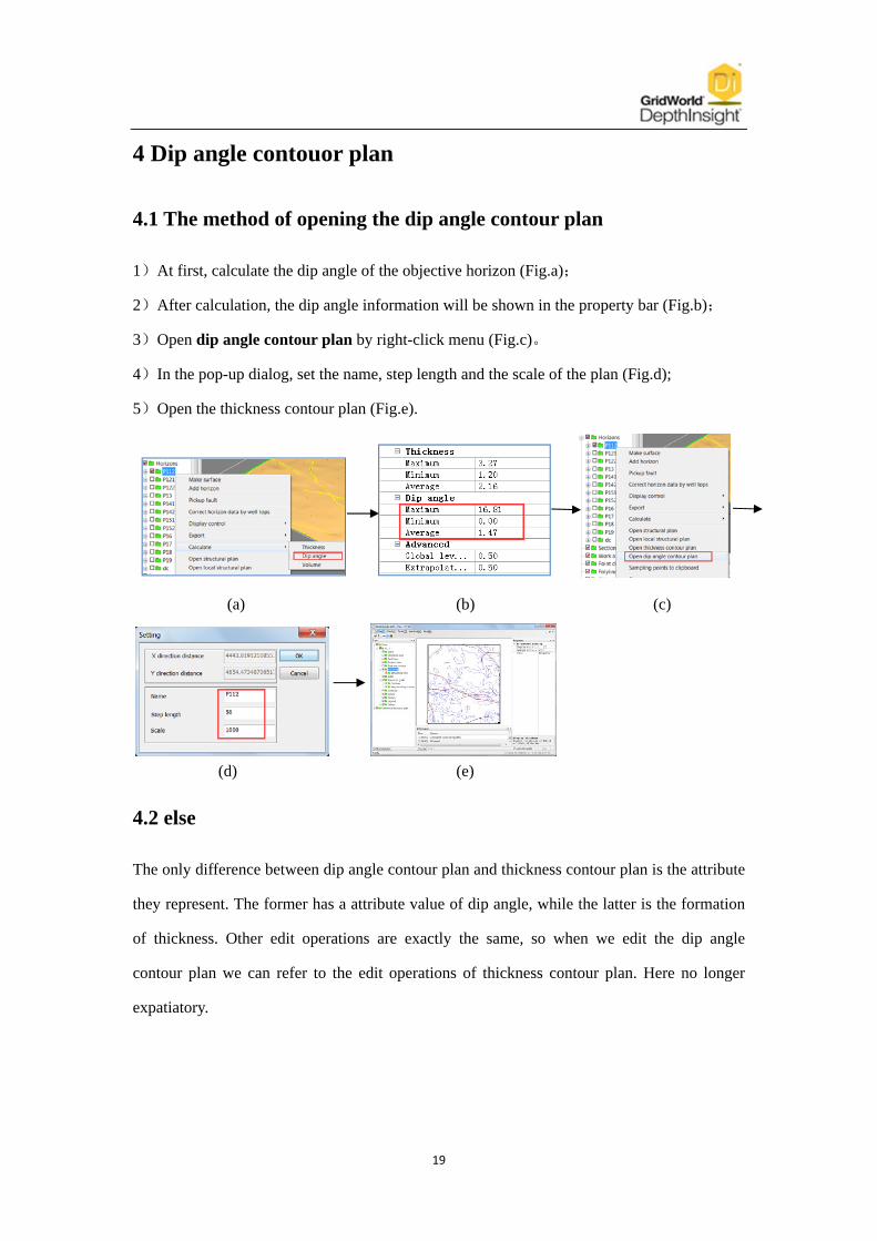
4 Dip angle contouor plan
4.1 The method of opening the dip angle contour plan
1)At first, calculate the dip angle of the objective horizon (Fig.a);
2)After calculation, the dip angle information will be shown in the property bar (Fig.b);
3)Open dip angle contour plan by right-click menu (Fig.c)。
4)In the pop-up dialog, set the name, step length and the scale of the plan (Fig.d);
5)Open the thickness contour plan (Fig.e).
(a) (b) (c)
(d) (e)
4.2 else
The only difference between dip angle contour plan and thickness contour plan is the attribute
they represent. The former has a attribute value of dip angle, while the latter is the formation
of thickness. Other edit operations are exactly the same, so when we edit the dip angle
contour plan we can refer to the edit operations of thickness contour plan. Here no longer
expatiatory.