user guide template - mine excellence
TRANSCRIPT

1
BLADES
Instruction Manual
Web User Guide
BLADES User Manual
©2018 Mine Excellence This user manual is intended to provide instructions only and does not imply a promise of any
service. Access to certain features will vary from account to account.

2
TABLE OF CONTENTS
S.NO TOPIC PAGE
NO. 1 EXECUTIVE SUMMARY 3
2 GUIDELINES FOR MANUAL USAGE 4
3 CLOUD BASED DESIGN SOFTWARE FOR OPEN PIT 5
4 CENTRAL DATABASE INFORMATION 6
5 STARTING THE WEB APPLICATION 7
6 BLADES MAIN MENU 8
7 NEW BLAST DESIGN 9
8 IMPORT BLAST DESIGNS 12
9 MANAGE EXISTING DESIGNS 17
10 BLAST DESIGN OUTPUT 20
11 FRAGMENTATION 25
12 AIR VIBRATION 26
13 GROUND VIBRATION 36
14 FLY ROCK/BLAST CLEARANCE 40
15 SYNC WITH BIMS . 42
16 REPORTING FEATURE 44
17 SAMPLE REPORTS 45
18 QA/QC 47

3
EXECUTIVE SUMMARY The software allows easy design of blasts, calculates blast parameters i.e. burden,
spacing, square/staggered pattern layout, and layout with charging options. The
program provides designed output, charts and graphs, as well as reports, in real-time
and allows output of data via customizable printing capabilities.
Surface blast design software provides design of blasting pattern according to rock
conditions, rock structure, and conditions required for optimized results, considering
explosives, drilling, environmental restrictions, equipment sizing and subsequent
operations.
In BLADES (Blast Designer), the pattern drawn can also be saved and blaster can be
provided with the charging sheet. It gives approximate vibration values, fragment size
and an initial idea about the danger zone. Empirical constant inputs are utilized for first
design output calculations.

4
However, once data has been accumulated by the use of BLADES then the historical
data can be used to determine the specific constants for each pit/bench. Predictions of
the rock fragmentation, air and ground vibration prediction and fly rock are obtained.
Software has Drilling and Blasting cost analysis capabilities too.
Key features include:
• Design of new blasts, manage existing blast records and generation of post blast
design reports as required by the user
• Generation of charging and drilling sheets which can be provided to blaster and
driller respectively to be utilized directly on the field
• Prediction of fragmentation, air and ground vibrations and fly rock based on the
selected blast design input parameters
• Cost analysis option for drilling and blasting costs
• Optimization of blast designs based on cost and post blast predictions
• Generation of regulatory/ mine-specific triggers/alerts to assess the post blast
predictions and re-design the blast as required by the user
GUIDELINES FOR MANUAL USAGE The intent of this user’s guide is to provide you with an overview of the applications and each
of the modules, but not to provide details on the modules’ use. BLADES contains an extensive
help system that provides detailed instructions on how to use the modules and applications.
This guide is designed to function together with the on-line Help system and can best be used
to help orient you with BLADES. It contains descriptions of the modules and applications, as
well as general information about their use and relationships. Each chapter also contains a list
of reports that can be generated from each module. There is a chapter listing all the reports with
instructions for their display, use and distribution. In general, this guide provides an
introduction to the applications with on-line Help providing the detail.
CLOUD BASED DESIGN SOFTWARE FOR OPEN PIT This manual mainly focuses on the features of BLADES and its working. To check out
all the open pit software available on the MineExcellence web portal, check the
snapshot provided below:

5
Figure: All Open Pit Blasting Software
CENTRAL DATABASE INFORMATION Database Information has to be provided in the beginning by the user and would be
visible in each and every software. It includes information about the mine, pit, zone,
bench as well as details about explosive, initiating devices, vibration instrument and
rock characteristics. Further, any additional information can be stored depending on the
user’s requirement.

6
Information Information
Figure: Central Database Information Capture
Information
should be stored
in central
database prior
to entering
blades

7
STARTING THE WEB APPLICATION
You start BLADES as illustrated in the figure below:
Figure Opening BLADES
Click Here

8
BLADES MAIN MENU
Main menu gives five options to the user: Perform a new blast design, manage existing
blast designs, quick generation of reports and optimization and analysis of existing
designs. The optimization and analysis features are available in the enterprise version
of BLADES.
BLADES TASK BAR
DESIGN: this shows the options on clicking [+] sign, new/import design/open these will lead to
respective pages.
REPORT: on clicking the [+] icon few options confining your report size will appear, you can select as
desired.
ABOUT: this gives a brief description of ‘BLADES’.
CLOSE: clicking on this will lead you to the dashboard of mineexellence.
SELECT LANGUAGE: ‘BLADES’ provides us with an additional feature of selecting language, either in
English or Spanish.

9
NEW BLAST DESIGN
New Blast Design: To design a new blast or to open an existing blast design, click the
main menu accordingly. Now you can enter mine details in the given format.
Design Number: Reference Number for Design. This is auto-generated. It generates in
following format – “MineName_DateTime”
Design Name: Unique Name for your Blast Design. Please specify the design name in
following format – “Zone/Face Name.”
Mine Name: Select from the dropdown combo box. If not given in the combo box then
go to Mine Details (Surface) information and add that name.
Pit: Select from the dropdown combo box. If not given in the combo box then go to
Mine Details (Surface) information and add that name.
Zone/Face: Select from the dropdown combo box. If not given in the combo box then
go to Mine Details (Surface) information and add that name.
Bench: Select from the dropdown combo box. If not given in the combo box then go to
Mine Details (Surface) information and add that name.
Type of Blasting: Select from the dropdown combo box.
Figure: Inserting preliminary mine detail
Insert Preliminary Mine Details

10
Blasting Quantity: This is the basic parameter using which the blast would be
designed. It can be filled in either m3
or tones.
The following are to be filled in:
Blast Date: Fill in the blast date. For example, DD/MM/YYYY (21/05/2005).
Blast Time: Fill in the blast time. For example, hours/minute/second (09:30:45).
Important to note is that hours should be in 24 hours. e.g. 2.45 p.m. should be entered
as 14.45.
Face Location Coordinates can be filled manually or can be imported. You should
enter the face coordinates provided by the surveyor over here. Click on the dropdown
to enter coordinates in Easting, Northing and RL instead of X, Y and Z.
Blast Location can be imported via digital file/photo, map or drone.
Figure 6 : Input/Import Face Coordinates
Figure 7 : Blast Location Importing Options
Click Here
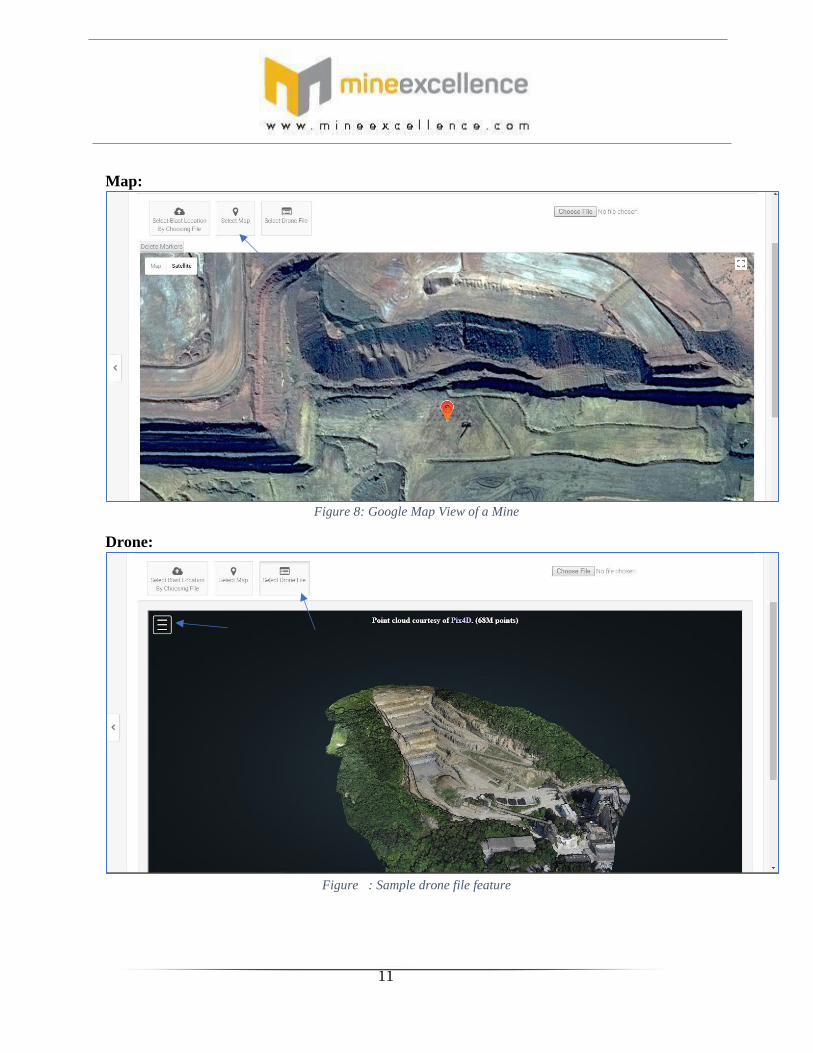
11
Map:
Figure 8 : Google Map View of a Mine
Drone:
Figure : Sample drone file feature

12
One can assess the measurements like height, distance, angle and area of blast
using the drone menu:
Save: On saving this information, Blast ID is generated.
Close: If you do not want to save this information, click the CANCEL button.
The unique ID number for the blast is generated and shown with a short name.
Example: Blast No. MIN_20180103_01. The first 3 letters shown are from the Mine
name itself, followed by year, month and date of the blast and the last letters i.e. “01”
means it is the first blast of the day.
Next: After completing the above form go to next form.
Figure : Drone specific advanced features

13
IMPORT BLAST DESIGN
Step 1: fill the following mandatory information of the respective mine :
DESIGN NUMBER
DESIGN NAME
MINE
PIT
ZONE/FACE
BENCH
TYPE OF BLASTING
DATE AND TIME
Step 2: click on browse and then import the file.
The imported file format should be in the format of MS Excel.
Browse the
respective file
from its location.
Then “IMPORT"

14
You will see the following on the screen .
DOWNLOAD BLANK SHEET
- One can also download a blank sheet in case they want to fill data and then import file.

15
-
Step 3: click on save and then next

16
MANAGE EXISTING DESIGNS
- Click on this icon to apply filter to your search
The following page will pop up on screen on clicking on filter icon:
Click
here
Here

17
Figure: Fly rock, Fragmentation, Vibration and Explosive Filters available
Select the Design you want to manage and click on edit button for that particular
Design.
If you are satisfied with the preliminary inputs page, you can move onto the
secondary inputs page by clicking on Next.
Select the record and click edit

18
- Secondary inputs include geometrical design parameters, explosives and accessories
used, inputs needed for the different predictors and costing information (optional)
i) Design Parameters:
1. Rock Name
2. Bench Height
Figure : Moving onto the secondary inputs page
Click Here

19
3. Bench width
4. Hole Diameter
5. Sub drill
6. Avg. Decking Height
7. Avg no. of decks
8. Face Angle
9. Vertical dip
10. Avg. Water Depth
ii) Required Fragmentation Size Distribution
1. Oversize
2. Optimum Size
3. Undersize
iii) Predictors Inputs
1. Distance
2. Charge per Delay/MIC
3. Air Site Exponent
4. Air Site Constant
5. Ground Site Exponent
6. Ground Site Constant
7. Fly rock Constant
Choose Pattern Details
Figure: Square, Staggered and Single Line pattern options available
- Click on Eye Icon to see Rock Characteristics:

20
Figure: Rock Characteristics page in the central database is directly accessible from here
Step: click on explosives, accessories and costing
to enter further details:

21
Fill in the explosive, initiating device and costing information as secondary inputs
to blast design
i) Explosives:
1. Stemming Material
2. Decking Material
3. Column Charge
4. Bottom Charge
5. Booster Charge
ii) Detonator:
1. Surface Detonator
Hole to hole delay
Row to row delay
Down the hole delay
Click here
22
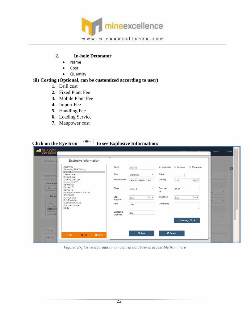
2. In-hole Detonator
Name
Cost
Quantity
iii) Costing (Optional, can be customized according to user)
1. Drill cost
2. Fixed Plant Fee
3. Mobile Plant Fee
4. Import Fee
5. Handling Fee
6. Loading Service
7. Manpower cost
Click on the Eye Icon to see Explosive Information:
Figure: Explosive information on central database is accessible from here

23
This green refresh button helps in re-populating the list of explosives (similar to
rock characteristics page).
Press Next to move onto subsequent pages.
Figure : Refresh button to re - populate the explosive list
Click Here

24
BLAST DESIGN OUTPUT
Figure: Blast Design Pattern
This page gives you Initial Blast Design with the blast pattern. You can change the
outputs here and pattern would be adjusted in real time.
i) Geometrical Parameters:
1. Face Length
2. Burden
3. Spacing
4. S/B Ratio
5. Hole Depth
6. Stemming Length
7. No. of Rows
8. Total holes
9. Meterage Drilled
ii) Explosives used per holes
1. Column Charge
2. Bottom Charge
3. Booster Charge
4. No. of Boosters
5. Total charge

25
iii) Blast Costs
1. Total Explosive Cost
2. Cost/Tones
3. Total Initiating System Cost
4. Stemming Cost
5. Total Drilling Cost
6. Total Manpower cost
7. Plant and other services
8. Total Blasting cost
iv) Blast Performance
1. Total Rock Broken
2. Powder factor
**Please Note: Regulatory/Mine specific triggers can be generated on the Blast Design
Output page that get dynamically updated as soon as the user makes any change in the
Blast Design parameters/pattern.
Figure : Charge variation possible by weight/length

26
ANALYZE
Analysis of blast design pattern can be done on the following
basis:
1) Wave front reinforcement :It helps the user determine
the direction in which either ground or air waves get reinforced. If this direction is
the same as the direction of inhabitants/wildlife nearby then the pattern delay must
be changed to change this direction.
BLAST DESIGN PATTERN– WHITEBOARD MODE
white board

27
Air Wave Ground Wave (P wave,
2200m/s)
2) Time window analysis : This analysis helps the user understand
his/her charge per delay based on the number of holes going off simultaneously in a
specified time window (usually 8ms as per international blasting standards)

28
Figure : Time Window Analysis
**This analysis can be utilized to determine the charge per delay associated with
the pattern. The charge per delay is usually used in calculation of air and ground
vibration using standard scaled distance square root and cube root formulas.
3) Firing Sequence Simulation : The user can check out
the sequence in which his pattern would get fired. This can aid in understanding if
there is any misfire/ cut-off happening prior to conducting the blast.
Using the firing sequence simulation module, the user can:
1. Understand the sequence in which the holes detonate/fire off
2. Predict a possibility of misfire happening because of TLD getting cut-off
3. By entering the maximum delay, the user can see that how many holes would
have gone off in that specific time frame.

29
Figure : firing sequence simulation
Speed variations are possible to be done in this module (1=Fastest, 10= Slowest)
**Please note: Pattern Zoom In, Zoom Out, Undo and Redo are standard
functionalities also present in our system. X and Y Coordinates are displayed for each
points in the pattern whiteboard.
Right clicking on each hole provides with the hole detail menu:

30
Figure: blast plan, in hole details and fragmentation details
: this icon avails us to download a blast plan in image format.
:by clicking on this icon, we can download the blast plan in pdf format.
: this icon allows us to select multiple holes on the blast plan.
: this icon is used to erase something on the blast plan.
: this icon is used for zoom in option.
: this option is for zoom out option.
: this option is for undo on the blast plan.
: this option is for redo on the blast plan.
Hole details
and
fragmentation
details of a
hole

31
Hole Detail Menu:
In this menu several important parameters can be filled:
1. Hole Depth
2. Burden and Spacing
3. Stemming Height
4. Hole Diameter
5. Vertical Dip and its error
6. Dip Azimuth and its error
7. Water Depth
8. Blockage in hole
9. Number of decks
10. Type of charge in the hole: column, bottom and booster
**There is also a provision to see the down the hole characteristics of the hole in 2D
drawing based on different selections made by the user. This can aid in
conducting/ensuring post drilling QA/QC operations to optimize blast designs in a
better manner.
FLYROCK DETAIL MENU:

32
This will show all the details of fly rock related to that selected hole
It will show the following:
- Burden of that hole
- Vertical dip of the hole
- Hole diameter
- Stemming length in that hole
- Charge mass
- Rock constant - Throw in front face by that hole
- Throw behind the face by that hole
- Row number label of that hole - Hole number of that hole
BLAST DESIGN PATTERN (DRONE MODE): It contains features like face flip,
pattern draw and firing sequence simulation

33
Change delay value : using this you can change the delay values.

34
Charging Sheet Tab : this gives the information of charging
of holes in sheet format.
Figure: Charging sheet (it gets dynamically updated if user makes any change in parameters)
**Charging sheet can be exported in a standard excel format by clicking on
this icon given at the end of the sheet. Another
option for the user is to simply export the drilling sheet (dip sheet) in an excel format
to be provided to the driller.
**Charging sheet can also be edited according to the desire/field requirement by
clicking on
button given at end of the page.

35
Drilling Sheet Tab : This tab provides all the information
related to the drilling of the holes in the sheet format.
**similar to charging sheet tab this tab also provides the exportation of drilling sheet by
clicking on the export drilling sheet icon. Another option
for the user is to simply export the drilling sheet (dip sheet) in an excel format to be
provided to the driller.

36
FRAGMENTATION
Figure: Kuz-Ram model fragmentation predictions
**Kuz-Ram and Modified Kuz-Ram Model has been implemented for obtaining a
prediction of the initial fragmentation i.e. percentage undersize, in-range and
oversize and its corresponding cumulative size distribution graph and table.
*You can select any of the above models for the further calculations according to our desired results.

37
Figure: Cumulative size distribution semi-log graph and table
The user can increment sizes according to his requirement and see dynamic
changes in the size distribution table and corresponding graph.
**This fragmentation page may give you opportunity to understand the expected
fragmentation in comparison to both P80 and P50 sizes.
This gives the
graphical analysis
of fragmentation
size.

38
AIR VIBRATION
This is Air Vibration Page. Here you can calculate Air vibration by entering
Distance, Charge per Delay, Site Law exponent, Site Law constant.
Here you can also draw contours at desired air vibration angle.
This also gives a warning message if any infrastructure is in danger due to
blast on that infrastructure.
It also gives the distance from the point of blast along with information of
the vibration level at that distance.

39
Figure 39: Air Vibration Contouring
Here you can Draw Vibration Contours at your desired interval and with desired
numbers of contour lines.
Vibration table would be generated for user’s reference to explore different
distance and charge per delay scenarios.

40
Figure : Air Vibration table (based on distance and charge per delay values)
**This table is Determination of Sound Intensity(dBL) based
on Distance(m) and Charge(kgs)Per Delay / MIC distance
V/S Charge(kgs)Per Delay / MIC.

41
GROUND VIBRATION
Figure: Ground vibration prediction and contouring
Very similar to air vibration, the ground vibration page can be utilized to
predict the ground vibration values at different distances based on the
charge per delay, exponent and constant fed into the system.
It consist of an addition feature of the followings:
1. Comparing MIC
2. Calculating ground vibration
3. Infrastructure contours

42
Infrastructure contour mode:
A very similar vibration table can also be generated for ground vibration in mm/s.
Figure: Vibration table for ground vibration

43
BLAST CLEARANCE ESTIMATION
Figure: Fly rock prediction is based on a fly rock constant and desired safety factor for plant and
personnel
This page lets you enter Blast Clearance Parameters and generates Blast
Clearance estimator result. You can change the parameters here and real
time tables, graphs and displays will be generated.
As we know that front throw depends on the burden whereas back throw
depends on hole inclination and stemming, hence these values can be
adjusted accordingly to see the variation in the 2 throws respectively.

44
TABLE:
Figure: fly rock front and back throw
GRAPH:
Figure: Front throw variation w.r.t Burden

45
DISPLAY: Fly rock angle (fly rock usually goes 90 degrees to the face) and fly rock circle radius
(Statutory limit to be imposed at your mine site) to be entered here:
Figure: Fly rock contours on-site along with safe distances for personnel, equipment and statutory limits
On clicking on this icon all the information regarding that perticular
column will be flashed on the screen, this function is available for the following :
1. Charge information
2. Fly rock constant for different types of rock type

46
SYNC WITH BIMS
Figure: Sync with BIMS feature for ease of data capture and analysis
**This option allows you to sync all the designs that you want with our blast
information management system (BIMS) to avoid redundancy in manual data
capturing.
Click here

47
REPORTING FEATURE
In this menu we can represent different reports related to blast details,
charging report, explosive and initiator consumption report & blast
prediction report. Other reports can be customized based on user’s
requirement.
Figure: Customize report menu

48
SAMPLE REPORTS
Figure: Report Sample 2
Figure : Report Sample 1

49
ANALYSIS: This section helps in analyzing our design
by comparing it with different designs by
alteration in various parameters.
This page comprises of various factors for
comparison like:
Geometrical parameters
Explosives used per hole
Blast costs
Fragmentation input data
Predicted fragmentation result
Predicted fragmentation in both

50
Graphical form
Tabular form
GRAPH:
TABLE:
For analysing the design click on the icon
on clickin on this icon
this will be flashed on the computer screen.

51

52
This section avails us the following
features: IMPORT
: if one
want to import a file
PDF : using this
we can download this result in pdf format
.
EXPORT
: using this we can export this result in
excel format.

53
QA/QC:
*QA/QC: Quality assurance and quality control this
sheet is for the analysis of both drilling and blasting for
the whole blast plan.
It provides with the following features
One can browse a file a from a location if
already downloaded and filled.

54
Download a blank sheet to fill the information
manually and then import the same file after
filling it.
OUTPUT PAGE OF QA/QC