user information ewefeoripp water meter pit
TRANSCRIPT

User information EWE-FLEXORIPP Water Meter Pit | 1
EWE-FLEXORIPPWater Meter PitInstallation and Operating Instructions
#710
0041
-Edi
tion
04/2
021
2 | User information EWE-FLEXORIPP Water Meter Pit
Table of contents
General information 4
Information about the product 6
Installation instructions (installation/assembly) 12
Shortening the pit pipe 16
Extension with TELERIPP 18
Operation and usage 22
Maintenance and servicing 22
Pit covers 24
User information EWE-FLEXORIPP Water Meter Pit | 3
4 | User information EWE-FLEXORIPP Water Meter Pit
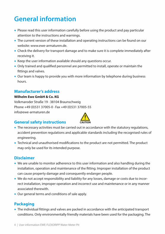
General information� Please read this user information carefully before using the product and pay particular
attention to the instructions and warnings.
� The current version of these installation and operating instructions can be found on our website: www.ewe-armaturen.de.
� Check the delivery for transport damage and to make sure it is complete immediately after receiving it.
� Keep the user information available should any questions occur.
� Only trained and qualified personnel are permitted to install, operate or maintain the fittings and valves.
� Our team is happy to provide you with more information by telephone during business hours.
Manufacturer‘s addressWilhelm Ewe GmbH & Co. KGVolkmaroder Straße 19 · 38104 BraunschweigPhone +49 (0)531 37005-0 · Fax +49 (0)531 37005-55 [email protected]
General safety instructions� The necessary activities must be carried out in accordance with the statutory regulations,
accident prevention regulations and applicable standards including the recognised rules of engineering.
� Technical and unauthorised modifications to the product are not permitted. The product may only be used for its intended purpose.
Disclaimer� We are unable to monitor adherence to this user information and also handling during the
installation, operation and maintenance of the fitting. Improper installation of the product can cause property damage and consequently endanger people.
� We do not accept responsibility and liability for any losses, damage or costs due to incor-rect installation, improper operation and incorrect use and maintenance or in any manner associated therewith.
� Our general terms and conditions of sale apply.
Packaging� The individual fittings and valves are packed in accordance with the anticipated transport
conditions. Only environmentally friendly materials have been used for the packaging. The
User information EWE-FLEXORIPP Water Meter Pit | 5
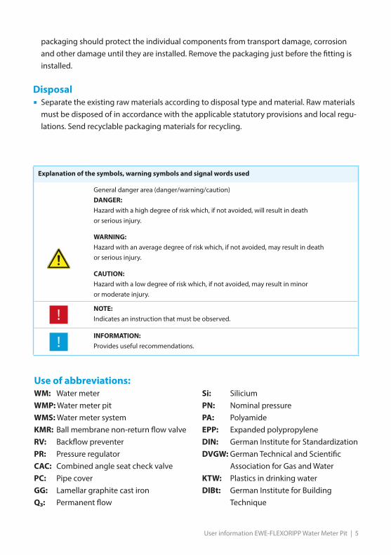
packaging should protect the individual components from transport damage, corrosion and other damage until they are installed. Remove the packaging just before the fitting is installed.
Disposal� Separate the existing raw materials according to disposal type and material. Raw materials
must be disposed of in accordance with the applicable statutory provisions and local regu-lations. Send recyclable packaging materials for recycling.
Use of abbreviations:WM: Water meter WMP: Water meter pitWMS: Water meter systemKMR: Ball membrane non-return flow valveRV: Backflow preventerPR: Pressure regulatorCAC: Combined angle seat check valvePC: Pipe coverGG: Lamellar graphite cast ironQ₃: Permanent flow
Si: SiliciumPN: Nominal pressurePA: PolyamideEPP: Expanded polypropyleneDIN: German Institute for Standardization DVGW: German Technical and Scientific Association for Gas and Water KTW: Plastics in drinking waterDIBt: German Institute for Building Technique
Explanation of the symbols, warning symbols and signal words used
General danger area (danger/warning/caution)DANGER:Hazard with a high degree of risk which, if not avoided, will result in death or serious injury.
WARNING:Hazard with an average degree of risk which, if not avoided, may result in death or serious injury.
CAUTION:Hazard with a low degree of risk which, if not avoided, may result in minor or moderate injury.
NOTE:Indicates an instruction that must be observed.
INFORMATION:Provides useful recommendations.

6 | User information EWE-FLEXORIPP Water Meter Pit
1. Information about the product1.1 ScopeThis user information applies to
1.2 Other applicable documents� The operating instructions of the respective contracting body or contracting company must be
followed
� DVGW (German Technical and Scientific Association for Gas and Water) and statutory accident insurance institution regulations
In particular:
� DIN EN 124, ”Gully tops and manhole tops for vehicular and pedestrian areas”
� DIN EN 805, ”Water supply - Requirements for systems and components outside buildings”
� DIN EN 806, ”Specification for installations inside buildings conveying water for human con-sumption”
� DIN 1988, ”Codes of practice for drinking water installations”, national supplement to DIN EN 806
� DIN EN 1717 ”Protection against pollution of potable water installations and general require-ments of devices to prevent pollution by backflow”
� DIN 4124 ”Excavations and trenches - Slopes, planking and strutting breadths of working spaces”
� DIN 18196 ”Earthworks and foundations - Soil classification for civil engineering purposes”
EWE-FLEXORIPP water meter pits article number: 0396XXX, Pit body, water meter system with flexible hoses and lifting device, pit ducts andinsulating cover.Pit covers must be ordered separately.
EWE-FLEXORIPP-pit covers (not supplied with the pit!):
FLEXORIPP cover cap max. 200 KG, article number 0396000
FLEXORIPP A15 pit cover consisting of a cover frame with cover seal, cover andlocking screws, article number 0396001
FLEXORIPP B125 pit cover consisting of a cover frame with cover seal, cover andlocking screws, article number 0396002

User information EWE-FLEXORIPP Water Meter Pit | 7
� KTW (plastics in drinking water) and elastomer guidelines issued by the Federal Environ-ment Agency
� List of ”Metallic materials suitable for contact with drinking water” issued by the Federal Environment Agency
� DVGW worksheet W 270 ”Propagation of microorganisms on materials used in drinking water systems”
� DVGW worksheet W 400 ”Technical rules for water distribution plants”
� DVGW worksheet W 543 ”Pressure-resistant hose pipes and compensators”
� DVGW worksheet W 570 ”Valves for drinking water installation”
� RSA 95 ”Guidelines for safeguarding work sites on roads”
� ÖNORM B 2538 “Water supply – requirements to water supply systems and their compo-nents outside buildings, supplementary policy to ÖNORM EN 805”
� ÖVGW QS W204 “Pressure-resistant flexible connection hoses”
� ÖVGW – W 501/1 “Fittings in the drinking water supply, part 1: overground and buried fittings”
� General technical approval / general homologation of the German institute for building technique (Deutsches Institut für Bautechnik) (white pit body)
1.3 Areas of use/medium� Cold drinking water in accordance with DIN 2000
1.4 Permissible operating pressure of components (PFA)� PN 10
1.5 Material/dimensions/performance
1.5.1 Pit body Material:
� Pit body made of waterproof PE
Dimensions:
� Pipe cover can be shortened in 2.5 cm sections
� Outer diameter with mounted pit cover: 548 mm
� Outer diameter without pit cover: 510 mm
� Pit opening/ inner diameter: 472 mm
� Largest width across corners: 650 mm
Connections:
� Female thread at both ends
� According to model 1” or 1.¼”
Pipe cover
Height without pit cover
Height with pit cover
Weight (KH/KH Q3 4)
0,75 m 0,80 m 0,87 m 25,6 KG
1,00 m 1,05 m 1,12 m 29,7 KG
1,25 m 1,30 m 1,37 m 33,6 KG
1,50 m 1,55 m 1,62 m 38,4 KG
1,75 m 1,80 m 1,87 m 42,5 KG
2,00 m 2,05 m 2,12 m 46,4 KG

8 | User information EWE-FLEXORIPP Water Meter Pit
1.5.1 Pit body, DIBt approved Material:
� Pit body made of waterproof, white PE
Dimensions:
� Pipe cover 1.25 m, can be shortened in a 2.5 cm pattern
� Outer diameter with mounted pit cover: 548 mm
� Outer diameter without pit cover: 510 mm
� Pit opening/ inner diameter: 464 mm
� Largest width across corners: 650 mm
Connections:
� On both sides internal thread: 1”
1.5.2 Insulating cover Material:
� Non-load insulating cover made of EPP
Dimensions:
� 485 mm outer diameter

User information EWE-FLEXORIPP Water Meter Pit | 9
Drawing: dimensions FLEXORIPP water meter pit
External Ø with A15/B125 pit cover installed
External Ø without pit cover
Internal ØPi
pe c
over
Hei
ght w
ith fr
ame
See table on page 7 for detailed information about these dimensions!
Hei
ght w
ithou
t fra
me
Largest external Ø
10 | User information EWE-FLEXORIPP Water Meter Pit
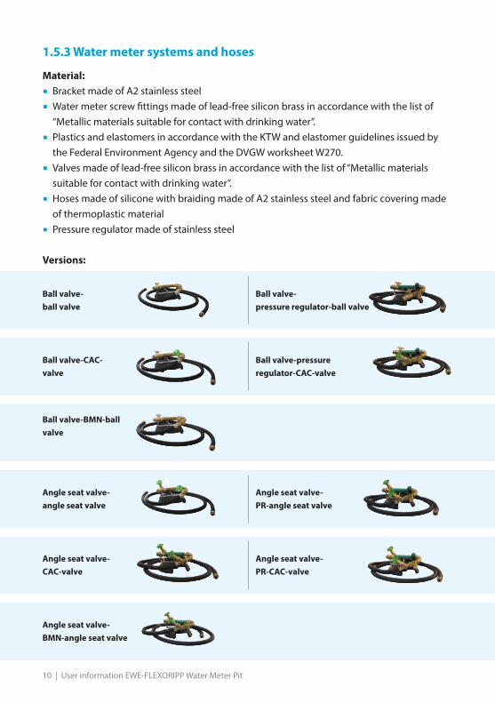
1.5.3 Water meter systems and hoses
Material:
� Bracket made of A2 stainless steel
� Water meter screw fittings made of lead-free silicon brass in accordance with the list of “Metallic materials suitable for contact with drinking water”.
� Plastics and elastomers in accordance with the KTW and elastomer guidelines issued by the Federal Environment Agency and the DVGW worksheet W270.
� Valves made of lead-free silicon brass in accordance with the list of “Metallic materials suitable for contact with drinking water”.
� Hoses made of silicone with braiding made of A2 stainless steel and fabric covering made of thermoplastic material
� Pressure regulator made of stainless steel
Versions:
Ball valve-ball valve
Ball valve- pressure regulator-ball valve
Ball valve-CAC- valve
Ball valve-pressure regulator-CAC-valve
Ball valve-BMN-ball valve
Angle seat valve- angle seat valve
Angle seat valve- PR-angle seat valve
Angle seat valve-CAC-valve
Angle seat valve- PR-CAC-valve
Angle seat valve- BMN-angle seat valve
User information EWE-FLEXORIPP Water Meter Pit | 11
1.6 Transport and storageThe FLEXORIPP water meter pit should be transported and stored vertically in itsoriginal packaging until it is used. Do not stack the FLEXORIPP water meter pits. A burden on the insulating cover has to be avoided. Remove and dispose packaging directly before mounting.
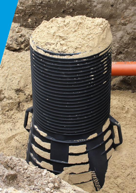
1.7 Functional descriptionFLEXORIPP water meter pits are intended for installation in pipe trenches.They can be used in many ways, such as a domestic connection, construction site waterconnection, in park areas or allotments, on camping sites or in cemeteries.The water meter pit is easy to install in a pipe trench without extensive earthworksbecause of its small size. The water meter pit is impermeable to surface water, hygienicallyclean and enables the frost-free operation of the water meter system and watermeter. It is not necessary or possible to enter the water meter pit.The relevant accident prevention regulations for entering pits are therefore notapplicable.
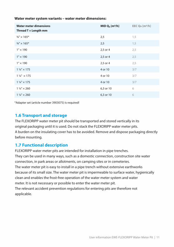
Water meter dimensionsThread T × Length mm
MID Q₃ [m3/h] EEC Qn [m3/h]
¾" × 165* 2,5 1,5
¾" × 165* 2,5 1,5
1" × 190 2,5 or 4 2,5
1" × 190 2,5 or 4 2,5
1" × 190 2,5 or 4 2,5
1 ¼" × 175 4 or 10 3/7
1 ¼" × 175 4 or 10 3/7
1 ¼" × 175 4 or 10 3/7
1 ¼" × 260 6,3 or 10 6
1 ¼" × 260 6,3 or 10 6 *Adapter set (article number 3903075) is required!
Water meter system variants – water meter dimensions:
12 | User information EWE-FLEXORIPP Water Meter Pit
Installation instructions (installation/assembly)2.1 Information about the preparations
The installation can be realized at temperatures under 0° C.Check the water meter pit and water meter pit system for damage or
contamination before use. A damaged pit or damaged fitting must not be used.The pipe should be flushed before installing the water meter in the water meter system;an adapter should be used for this purpose.
The water meter pit system is factory fitted with a PE adapter.The PE adapter is only used as a substitute for the water meter and is notsuitable for operation.
2.2 Information about the installation siteThe water meter pit should be located at an elevated position on the site orprotrude a few centimetres above ground level if possible.
The choice of pit size should be compatible with the frost-free installation depthof the pipe and is the sole responsibility of the user. The water meter pit demonstratesfavourable behaviour against buoyancy because of its external shape. An essentialrequirement is that it is installed properly with gravel backfill and compaction in layers.The pit body has a waterproof design and the connection to the cover is impermeable tosurface water. A soil engineering specialist should be consulted in areas where there is arisk of temporary flooding.
Should there be flat-lying supply pipes (so-called summer pipes) downstream ofthe water meter pit, which have to be emptied before the start of the frost
season, we recommend installing a special fitting in the pipe routing between thepit exit and the tapping point, e.g. an EWE garden valve in combination with aninstallation set. An EWE garden hydrant provides the same convenience in the case ofan outdoor tapping point.
The emptying of the downstream supply pipe in the pit body requires specialcare from a hygienic point of view. The water from the pipe must be pumped
away immediately during the emptying phase and then the drain opening mustbe closed to prevent any possible contamination in the pipe network.
User information EWE-FLEXORIPP Water Meter Pit | 13
2.3 Excavation and backfillingThe water meter pit is delivered ready for installation and can be used in preparedditches. The work required is the responsibility of the user.The distances to other underground installations, such as buildings, pipes, cables, mustbe observed in accordance with the DVGW worksheet W 400.The requirements of DIN 4124 must be observed.Possible earth movements as a result of subsidence, settlement or soil pressure, e.g.caused by sloping sites, must be taken into consideration.Non-cohesive soil with a grain size of max. 16 mm must be used for the foundations,bedding and backfilling. Sand SE, SW or SI and gravel GE, GW, GI have proven a successin accordance with soil classification F1 according to DIN 18196, which also meet therequirements for the compaction classes and frost protection.The pit must be fixed in place as soon as possible by backfilling the trench.Other appropriate measures must be taken to secure it against floating while the trenchis not completely backfilled to ground level.

14 | User information EWE-FLEXORIPP Water Meter Pit
1.� Level out and compact the bottom of the
trench evenly throughout.
� Position the pit so that it is vertical and level.
� Arrange for the foundations for the foot-print of the pit to be dug in accordance with load class A15 or B125.
2.4 Installation
2.� Arrow - Observe the flow direction when
aligning the pit.
3.� Flush the pipe before establishing the
connections.
� Establish connections between the con-nection sleeves of the pit and the pipe.
� Observe the guidelines of the connection fittings manufacturer.
�
The leak test should be carried out before backfilling, otherwise the
sealing points outside the pit can no longer be checked.

User information EWE-FLEXORIPP Water Meter Pit | 15
5.� Install the water meter in accordance with
section 4 “Maintenance and servicing”.
6.� Install the pit cover in accordance with
section 5 “Pit covers”.
The pit may not be operated without a pit cover in accordance with section 5.The insulating cover is non load-bearing. The installation site and pit opening must
be secured against unintentional access during the installation period.
4.� Backfill the trench in the area of the water
meter pit.
� Support the connection pipes (inlet and outlet side) before the compacting.
� Backfill the soil in layers of max. 30 cm and compact to 97% DPr.
� Avoid one-sided stress when backfilling and compacting.

16 | User information EWE-FLEXORIPP Water Meter Pit
2.5. Shortening the pit pipeThe cylindrical, rib-shaped part of the pit can be shortened in 2.5 cm sections.At least 3 ribs need to remain to mount the cover frame and its seal.Frost protection through the planned installation depth must be taken intoconsideration.
1.� Remove the cover if one is fitted.
2.� Loosen and also remove the cover frame
(if applicable).
3.� Remove the cover frame seal
(if applicable).
4.� Remove the insulating cover.

User information EWE-FLEXORIPP Water Meter Pit | 17
5.� Take the measurement to the surface.
6.� When using the cover cap, make sure that
the pit together with the cap protrude approx. 7 cm above the ground.
� When using the A15/B125 pit cover, add its height of 7 cm from the first rib.
7.� The pit pipe can be shortened in sections
of 2.5 cm at the deepest point of the rib using a suitable tool (e.g. EWE-FLEXORIPP cutter).
� A minimum of three ribs must remain.
8.� Deburr the cut edge.
� Deburr the first rib at its deepest point.
� Install the pit cover in accordance with section 5 “Pit covers”.
If shortened by more than 20 cm, the length of the lifting line must be reducedor the latter must be replaced.

18 | User information EWE-FLEXORIPP Water Meter Pit
2.6. Extension of the pit body with help of the TELERIPP top part
2.6.1. Material / dimensions / performance Material:
� TELERIPP top part made of waterproof PE
� TELERIPP sealing made of NBR
Dimensions:
� 750 mm outer diameter of the TELERIPP top part
2.6.2. DescriptionWith the TELERIPP top part a subsequent tight extension of the pit body in an arbitrary desi-red height from 70 mm to 250 mm is possible.
2.6.2. Installation tip for the TELERIPP top part
1.� Remove cover if one is fitted.
Article number 0396008 Consisting of:TELERIPP top part, frame sealing, sealing TELERIPP, lubricant for plastic pipes with rubber sealing 150g
User information EWE-FLEXORIPP Water Meter Pit | 19
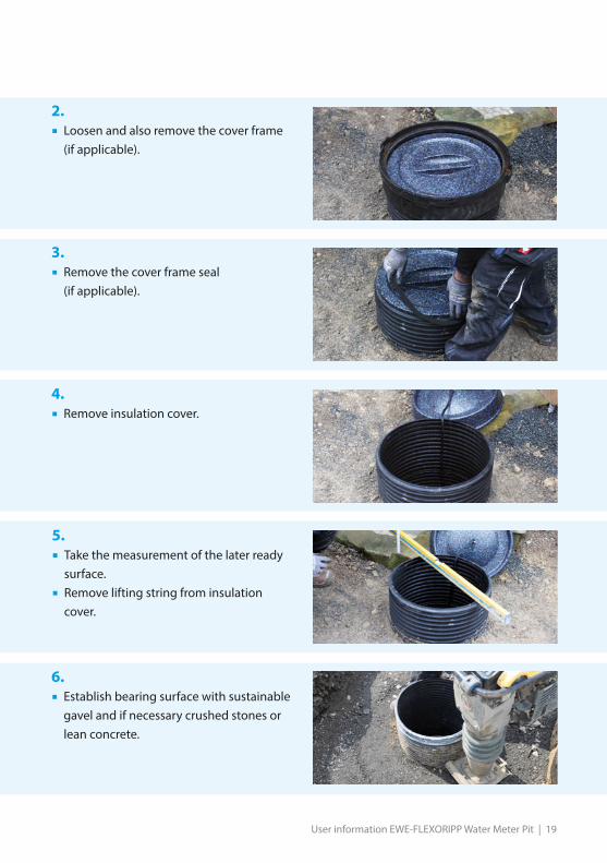
2.� Loosen and also remove the cover frame
(if applicable).
3.� Remove the cover frame seal
(if applicable).
4.� Remove insulation cover.
5.� Take the measurement of the later ready
surface.
� Remove lifting string from insulation cover.
6.� Establish bearing surface with sustainable
gavel and if necessary crushed stones or lean concrete.
20 | User information EWE-FLEXORIPP Water Meter Pit
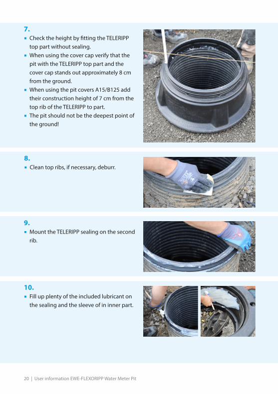
7.� Check the height by fitting the TELERIPP
top part without sealing.
� When using the cover cap verify that the pit with the TELERIPP top part and the cover cap stands out approximately 8 cm from the ground.
� When using the pit covers A15/B125 add their construction height of 7 cm from the top rib of the TELERIPP to part.
� The pit should not be the deepest point of the ground!
8.� Clean top ribs, if necessary, deburr.
9.� Mount the TELERIPP sealing on the second
rib.
10.� Fill up plenty of the included lubricant on
the sealing and the sleeve of in inner part.

User information EWE-FLEXORIPP Water Meter Pit | 21
11.� Apply the TELERIPP top part loose.
14.� Clean the top rib of the TELERIPP,
if necessary, deburr.
15.� Insert the cover sealing in the rib dales of
the TELERIPP top part.
� Place the thin lip down, outside fitting to the rib.
� Observe position and layer of the sealing.
� Mount the cover cap according to chapter 5 “Installation instructions for cover cap”.
� Carry out rest of the filling.
12.� Push the TELERIPP top part with force over
the sealing.
� Check the correct position on the bearing area.
13.� Fix the lift cord at the insulation cover.
� Insert the insulation cover.

22 | User information EWE-FLEXORIPP Water Meter Pit
3. Operation and useA visual inspection of the water meter pit, the water meter pit fittings and the entiresystem must be made prior to putting it into operation.
3.1 Functional check and leak testThe entire system must be checked to ensure that it is working and has no leaks.
3.2 Pit security The pit must not be operated without a pit cover in accordance with section 5.
The insulating cover is non load-bearing.The installation site and pit opening must be secured against unintentional
access during the installation period and during operation of the pit.A15/B125 pit covers must be locked with the enclosed screws.
3.3 Frost protectionThe insulating cover fastened to the lifting line must be used.Frost protection must be ensured through the local installation, in particular by
the right choice of installation depth.It is therefore the sole responsibility of the planning and contracting body to ensure thefrost-free conditions in the pipe and pit.
4. Maintenance and servicingThe (ball) shut-off valves in the water meter systems are generally defined asmaintenance fittings; they should therefore be actuated slowly in the case of
maintenance (during opening and closing) when the tapping devices are closed.The fittings must be opened as far as they will go, i.e. by setting them to the fully openposition. It is not permitted to restrict them.
It is recommended that the shut-off valves on the water meter system arenormally actuated at least once a year to ensure that they work and move
freely.As a general rule, an annual functional check should be performed on the non-returnflow valve. It is not necessary for plug-in non-return flow valves to be inspected annually.These fittings must be changed with the regular replacement of the water meter, butwithin 10 years at the latest (EN806). The non-return flow valves are wear parts.A functional check can be carried out on models with a control screw that are alreadyinstalled.To do this, the inflow must be shut off and the control screw opened with due caution.

User information EWE-FLEXORIPP Water Meter Pit | 23
Only the remaining water between the inflow and housing must escape.Medium from other installations must be held back by the non-return flow valve.The non-return flow valve must be repaired if this is not the case.
The pipe system must be shut off and depressurised before starting the repairwork. Furthermore, the pipe system must be secured against inadvertent useagain.
It is possible to change all the built-in components with a special tool. Please contact your local dealer.
1.� Remove the cover and insulating cover.
� Pull out the water meter pit system with the aid of the lifting line.
2.� Place the water meter pit system next to
the pit opening.
3.� Alternatively, the pit system can be fixed
with the plinth on the pit frame.
� Close the valves on both sides.
� Install and replace the meter taking account of the installation instructions of the water meter manufacturer.
� Loosen cap nuts.
� The water meter stored with a slight tension in the water meter pit system can now be removed from this storage (bra-cket) with little effort.
4.1 Meter reading and meter replacement
24 | User information EWE-FLEXORIPP Water Meter Pit
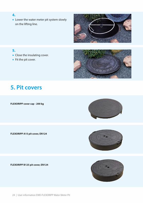
FLEXORIPP B125 pit cover, EN124
4.� Lower the water meter pit system slowly
on the lifting line.
5.� Close the insulating cover.
� Fit the pit cover.
5. Pit covers
FLEXORIPP cover cap - 200 kg
FLEXORIPP A15 pit cover, EN124
User information EWE-FLEXORIPP Water Meter Pit | 25
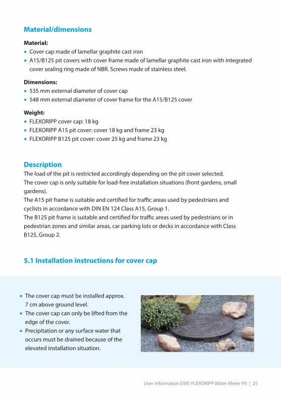
� The cover cap must be installed approx. 7 cm above ground level.
� The cover cap can only be lifted from the edge of the cover.
� Precipitation or any surface water that occurs must be drained because of the elevated installation situation.
Material/dimensions
Material:
� Cover cap made of lamellar graphite cast iron
� A15/B125 pit covers with cover frame made of lamellar graphite cast iron with integrated cover sealing ring made of NBR. Screws made of stainless steel.
Dimensions:
� 535 mm external diameter of cover cap
� 548 mm external diameter of cover frame for the A15/B125 cover
Weight:
� FLEXORIPP cover cap: 18 kg
� FLEXORIPP A15 pit cover: cover 18 kg and frame 23 kg
� FLEXORIPP B125 pit cover: cover 25 kg and frame 23 kg
DescriptionThe load of the pit is restricted accordingly depending on the pit cover selected.The cover cap is only suitable for load-free installation situations (front gardens, smallgardens).The A15 pit frame is suitable and certified for traffic areas used by pedestrians andcyclists in accordance with DIN EN 124 Class A15, Group 1.The B125 pit frame is suitable and certified for traffic areas used by pedestrians or inpedestrian zones and similar areas, car parking lots or decks in accordance with ClassB125, Group 2.
5.1 Installation instructions for cover cap
26 | User information EWE-FLEXORIPP Water Meter Pit
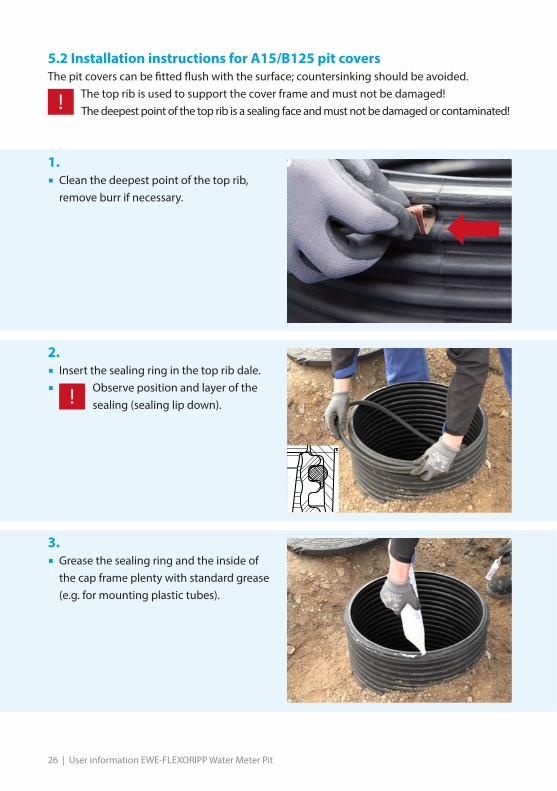
1.� Clean the deepest point of the top rib,
remove burr if necessary.
5.2 Installation instructions for A15/B125 pit coversThe pit covers can be fitted flush with the surface; countersinking should be avoided.
The top rib is used to support the cover frame and must not be damaged!The deepest point of the top rib is a sealing face and must not be damaged or contaminated!
2.� Insert the sealing ring in the top rib dale.
� Observe position and layer of the sealing (sealing lip down).
3.� Grease the sealing ring and the inside of
the cap frame plenty with standard grease (e.g. for mounting plastic tubes).
User information EWE-FLEXORIPP Water Meter Pit | 27
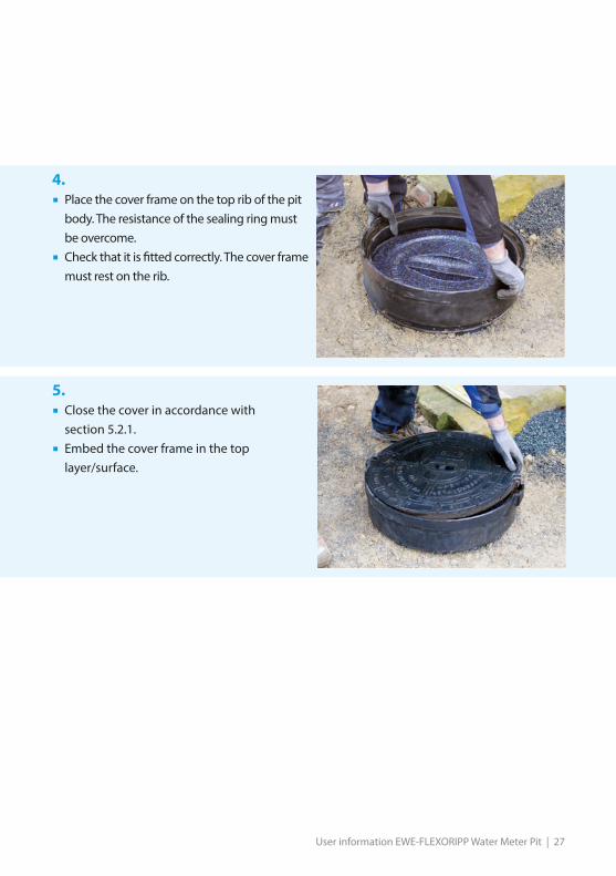
4.� Place the cover frame on the top rib of the pit
body. The resistance of the sealing ring must be overcome.
� Check that it is fitted correctly. The cover frame must rest on the rib.
5.� Close the cover in accordance with
section 5.2.1.
� Embed the cover frame in the top layer/surface.
28 | User information EWE-FLEXORIPP Water Meter Pit
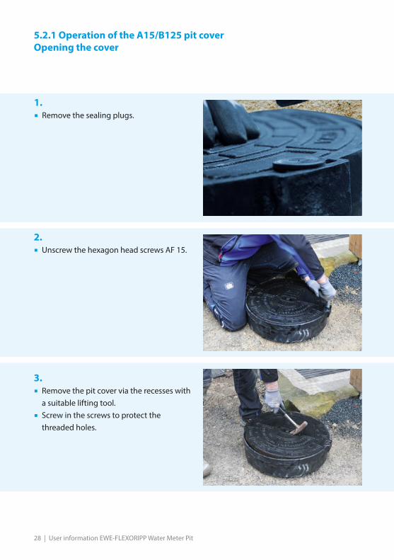
5.2.1 Operation of the A15/B125 pit coverOpening the cover
1.� Remove the sealing plugs.
2.� Unscrew the hexagon head screws AF 15.
3.� Remove the pit cover via the recesses with
a suitable lifting tool.
� Screw in the screws to protect the threaded holes.
User information EWE-FLEXORIPP Water Meter Pit | 29
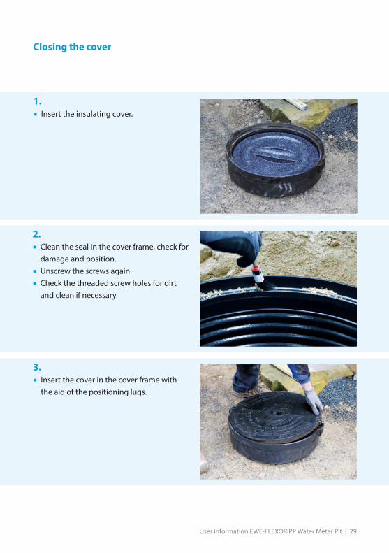
Closing the cover
1.� Insert the insulating cover.
2.� Clean the seal in the cover frame, check for
damage and position.
� Unscrew the screws again.
� Check the threaded screw holes for dirt and clean if necessary.
3.� Insert the cover in the cover frame with
the aid of the positioning lugs.
30 | User information EWE-FLEXORIPP Water Meter Pit
Alternative fixing with stud bolts and nuts
Accessory parts can be used to convert the pit covers A15 and B125 from screws to faste-ning with stud bolts and nuts.
Carry out the procedure as in 5.3.1, however, when opening or closing, make sure that the threads of the stud bolts are not damaged.
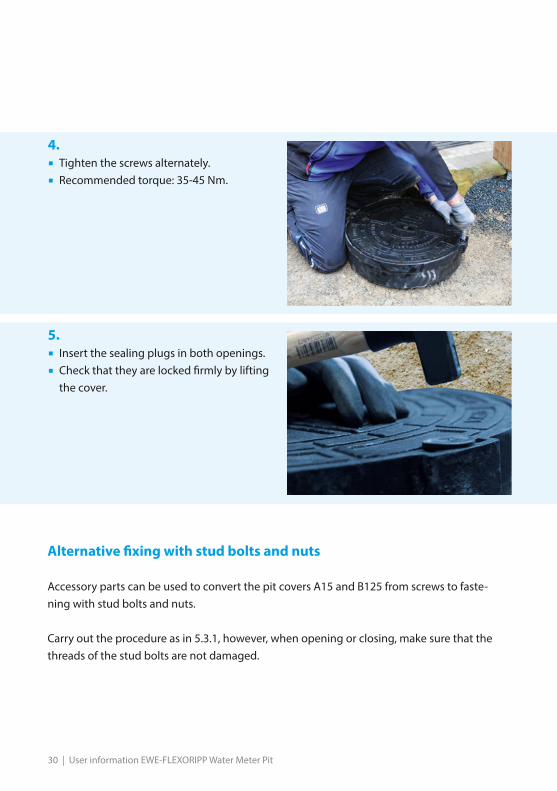
4.� Tighten the screws alternately.
� Recommended torque: 35-45 Nm.
5.� Insert the sealing plugs in both openings.
� Check that they are locked firmly by lifting the cover.

User information EWE-FLEXORIPP Water Meter Pit | 31

32 | User information EWE-FLEXORIPP Water Meter Pit
Wilhelm Ewe GmbH & Co. KGVolkmaroder Straße 1938104 Braunschweig
Phone +49 (0)531 37005-0Fax +49 (0)531 [email protected]
www.ewe-armaturen.de #710
0041
-Edi
tion
04/2
021