user instructions - flowserve · edward univalve user instructions english 12-13 2 ... adapter that...
TRANSCRIPT

1Experience In Motion
USER INSTRUCTIONS
FCD EVENIM2000-02(E)(Bulletin V-370 R3)
Edward ValvesUnivalve
InstallationOperation
Maintenance

EDWARD UNIVALVE USER INSTRUCTIONS ENGLISH 12-13
2
INTRODUCTION
EDWARD CUSTOMER SERVICE
Consult your Edward factory inside sales representative for information on obtaining repair tools.
As always, field sales and service personnel are available to assist with maintenance and repairs involving Edward valves. And they are backed up by factory-trained specialists to lend additional assistance whenever needed.
An improved low-maintenance Univalve design... tools for fast in-line repairs...and reliable Edward service!
Seat Refinishing Tool
Bonnet Torquing Collar
Seal Weld Cutting Machine
THREE TOOLS FOR FASTER IN-LINE REPAIRS OF EDWARD UNIVALVES
Edward Univalves aren’t likely to require any maintenance or repair work until they’ve been in services for quite a few years. But sooner or later – depending on the nature of the fluids, frequency of operation and time in service – Univalve seats and disks may need to be repaired.
The Seat Refinishing Tool has a self-centering head of multiple tungsten carbide cutters on a spindle which is hand-operated with a speed wrench for complete seat refinishing. Lapping or other finishing work is not required to produce refinished seats.
Seat damage, such as that produced by foreign materials in the line fluids, can be repaired quickly.
The Bonnet Torquing Collar is essentially a torque wrench adapter that is used to remove and reassemble the bonnet of an unwelded Univalve.
The tool facilitates reassembly of the bonnet with the required torque correctly applied to ensure that the graphitic body-bonnet gasket is properly loaded to establish a leak-tight seal. The tool may also be used to assemble and disassemble seal-welded valves.
The Seal Weld Cutting Machine has the ability to cut both fillet and canopy welds. By removing the handwheel and yoke, then installing the machine, seal welds can be cut, leaving a suitable weld prep. The machine is operated by one person and uses conventional plant air.
TABLE OF CONTENTS
Edward Customer Service ..............................................2
Three Tools for Faster In-line Repairs of Edward Univalves ........................................................2
Exploded View .................................................................3
Disassembling the Univalve ....................................... 4–5
Servicing Edward Univalve Stop and Stop-check Valves ..6
Servicing Edward Univalve Check Valves ........................7
Alternate Weld-cutting Methods for Univalves ................8
Univalve Maintenance Tools ..................................... 9–13
Reassembly of the Univalve ................................... 14–17Reassembly of Unwelded Bonnet Univalves .............14Reassembly of Welded Bonnet Univalves .................14
Replacing the Seal Weld Univalves ...............................18A105 and F22 Univalves ...........................................18F316 and F347 Univalves ..........................................18
Operational Recommendations ..............................19–20
General Information ............................................... 21–22
TABLES
Valves With No Prefix in Figure Numbers .............. 10–11
Valves With “B” Prefix Figure Numbers ........................12
Valves With “C” and “D” Prefix Figure Numbers* .........13
Unwelded Univalve Bonnet Gasket Torques ..................15
Welded Univalve Bonnet Torques .................................16
Torque Range for Packing Gland Bolts .........................17
Minimum Torque for Closing Valves — ft-lb on Main Seat .......................................................................19
Impactor Handle/Handwheel Performance Chart ..........20
EDWARD UNIVALVE USER INSTRUCTIONS ENGLISH 12-13
3
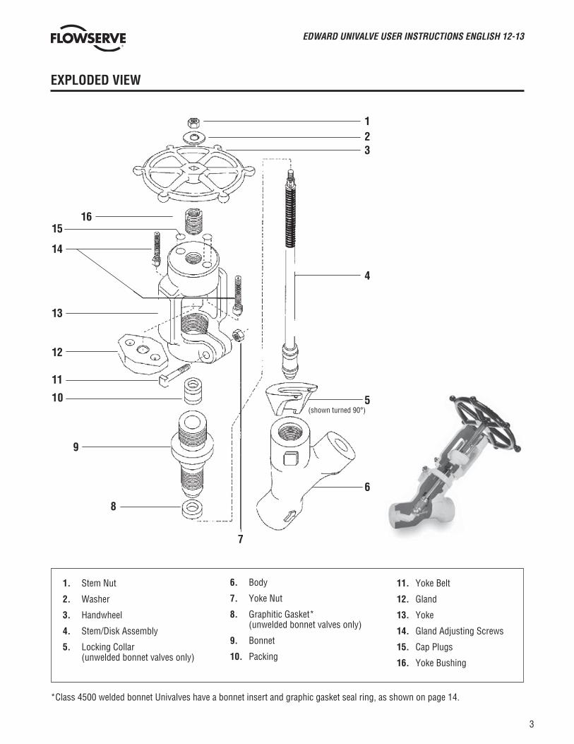
EXPLODED VIEW
123
5(shown turned 90°)
4
6
8
7
9
1615
14
13
12
11
10
*Class 4500 welded bonnet Univalves have a bonnet insert and graphic gasket seal ring, as shown on page 14.
1. Stem Nut
2. Washer
3. Handwheel
4. Stem/Disk Assembly
5. Locking Collar (unwelded bonnet valves only)
6. Body
7. Yoke Nut
8. Graphitic Gasket* (unwelded bonnet valves only)
9. Bonnet
10. Packing
11. Yoke Belt
12. Gland
13. Yoke
14. Gland Adjusting Screws
15. Cap Plugs
16. Yoke Bushing

EDWARD UNIVALVE USER INSTRUCTIONS ENGLISH 12-13
4
1. Double-check to make sure that line pressure has been relieved before disassembling the valve.
2. The valve should be in the open position and not against the body seat or backseat.
3. If the valve is manually operated, remove the lock nut that attaches the handwheel or impactor handle to the valve stem. Remove the handwheel or handle. If the valve is motor operated, remove the actuator from the valve stem.
4. Loosen the two gland adjustment screws that rest against the packing gland by threading them higher into the yoke. A hex allen wrench inserted into the top of the gland screw thru the holes in the top of the yoke (remove the dirt protectors first) will speed this up.
DISASSEMBLING THE UNIVALVE
Line pressure must be relieved before disassembling the valve.
5. Loosen the yoke clamp bolt and nut. It is not necessary to completely remove them.
6. Remove the yoke assembly by unscrewing it from the bonnet. A gentle tap with a hammer might be necessary before the yoke will unscrew away from the bonnet. You may find it easier to remove the yoke by placing the handwheel on the stem to prevent the stem from rotating. When the yoke is even with the top of the stem, and you can no longer use the valve handwheel or handle, you will need to grasp the lower portion of the stem between the yoke and bonnet. If the yoke is turning freely, a cloth may be adequate to hold the stem. If this is not adequate, a strap wrench that will not damage the stem surface should be used. If only the packing is to be replaced, this can now be easily done with no further disassembly of the Univalve. See Step 14.
7. If the yoke bushing is worn or damaged and must be removed, insert 1⁄8” (or smaller) abrasive grinding wheel into the slot on top of the bushing. Using a standard grinding tool, work the grinder downward to remove yoke metal that was upset into the bushing during the valve assembly. Periodically during the grinding process, try to turn the bushing within the yoke to test how loose it is becoming. Once loosened, use a screwdriver in the slot to turn the bushing. To reinsert a new bushing, thread it into the yoke so that the top of the bushing is flush with the top of the yoke. Using a chisel and hammer, tap the yoke metal into the bushing slot, creating an offset, so that the bushing is tight within the yoke.

EDWARD UNIVALVE USER INSTRUCTIONS ENGLISH 12-13
5
DISASSEMBLING THE UNIVALVE (continued)
11. Remove the valve bonnet-stem-disk assembly if the valve being repaired is a stop valve (figure XXX2X). The disk in a stop-check vaIve (figure XXX6X) and the bonnet insert in welded Class 4500 vaIves (figure 961XX) may be removed by forming a short piece of soft wire into the shape of an L and lifting it up in the disk bore.
12. Remove the stem from the bonnet. It may be necessary to rotate the stem through the packing before it can be removed.
13. If the valve is unwelded, the graphitic gasket must be replaced. Do so by removing it from the valve body, but take care not to damage machined surfaces.
14. Using a packing tool, remove the old packing. Stainless steel Univalves are equipped with a metal junk ring in the bottom of the packing chamber. (See pg. 16 for repacking instructions.)
8. If the valve is unwelded, remove the locking collar.
9. If the valve to be repaired is seal-welded, prepare the Seal Weld Cutting Machine for the weld cutting operation. If a cutting machine is not available, use one of the alternate methods shown on pg. 8.
10. Refer to the chart on pp. 10–13 to select the proper torquing collar assembly (consisting of lock nut and collar). Screw the torquing collar clockwise onto the bonnet until it bottoms. A left hand threaded lock nut is used to lock the torquing tool to the bonnet. Use the appropriate size open end or socket/box wrench (1-¼", 1-¾" or 2" hex) on the lock nut to turn the tool counterclockwise to remove the bonnet.

EDWARD UNIVALVE USER INSTRUCTIONS ENGLISH 12-13
6
If seat damage has occurred, outlined below are step-by-step procedures for fast, in-line repairs using the Edward Seat Refinishing Tool.
1. See pp. 4–5 for proper disassembly procedures before performing repairs on the Univalves. Then, using the charts on pp. 10–13, select the proper Seat Refinishing Tool Arrangement for performing repairs on the seat area.
2. Take appropriate caution to make sure the inlet and outlet valve ports are blocked to prevent removed seat material from entering the line. Then, screw the Seat Refinishing Tool Assembly into the body while holding the shaft up to prevent tool and seat contact. The guide needs only to be hand-tightened. Do not damage the cutters by dropping the tool on the stellite seat.
SERVICING EDWARD UNIVALVE STOP AND STOP-CHECK VALVES
Line pressure must be relieved before making any repairs.
3. The Seat Refinishing Tool is now ready for operation. Use a speed wrench to operate the tool. Because this manual process is fast, a special air or electric motor should not be used. The tool assembly can be easily removed to inspect the seat and determine if more seat refinishing is required. Turn the tool clockwise using light pressure only on the stellite seat.
Univalves can be reseated several times, assuming nominal amounts of stellite are removed each time. A typical resealing operation removes several thousandths of an inch of stellite; severe seat defects, of course, would remove more. A total of about .03 inch of stellite can be removed before the stellite becomes too thin, or approximately five average refinishing operations.
4. When a repair of the seat is finished, use a portable vacuum to remove loose chips.

EDWARD UNIVALVE USER INSTRUCTIONS ENGLISH 12-13
7
1. If the check valve to be repaired is seal-welded, prepare the Seal Cutting Machine for the weld-cutting operation. If a cutting machine is not available, use one of the alternate methods on pg. 8.
2. Once a seal-welded valve has been cut, it is ready for disassembly. Unscrew vaIve cover from the body using the flats provided.
3. Remove the check valve spring and disk from the body bore. A short piece of soft wire formed into an L shape may be used to assist in disk removal by engaging it in the groove inside the disk.
4. The check valve is now ready for internal work. See the section entitled “Servicing Edward Univalve Stop and Stop-Check Valves” (pg. 6) for correct repair procedures.
SERVICING EDWARD UNIVALVE CHECK VALVES
Line pressure must be relieved before servicing the valve.

EDWARD UNIVALVE USER INSTRUCTIONS ENGLISH 12-13
8
GRINDING A WELD
(For canopy seal Univalves) stainless steel valves
Open valve to backseat. Using a standard grinding wheel, remove the weld by grinding from the top of the body face and bonnet outside diameter (see photo). Continue this process around the valve until all weld is removed where the body and bonnet are joined together. Clean the valve with a wire brush. A penetrating oil may be used where permissible to loosen the threads joining the body and bonnet.
SCARFING A WELD
(For fillet-welded Univalves) carbon steel and low alloy valves
1. Air-arc method Open valve to backseat.
Using air-arc equipment, make a series of cuts in the valve weld (see photo and sketch). Continue making cuts until the valve weld takes on a grooved scarfed-out appearance. Clean the valve with a wire brush. A penetrating oil may be used where permissible to loosen the threads joining the body and bonnet.
2. Oxyacetylene method Open valve to backseat. Using an oxyacetylene torch equipped with a scarfing tip, make a series of cuts in the weld until it takes on a scarfed-out, grooved appearance. Clean the valve with a wire brush. A penetrating oil may be used where permissible to loosen threads joining the body and bonnet.
ALTERNATE WELD-CUTTING METHODS FOR UNIVALVES
Line pressure must be relieved before making any repairs.
This sketch shows the sequence of cuts necessary to remove the fillet weld by both oxyacetylene and air-arc methods. Place scarfing torch or welding electrode tangent to the bonnet, as indicated in position A. When metal reaches cutting temperature, start blowing oxygen or air while moving torch backward. Weld metal should be blown away. Move torch counterclockwise to position B. Repeat until entire fillet weld is removed and gap is continuous. DO NOT REMOVE EXCESS MATERIAL FROM BONNET OR UPPER BODY FACE.A
B

EDWARD UNIVALVE USER INSTRUCTIONS ENGLISH 12-13
9
UNIVALVE MAINTENANCE TOOLS
SEAT REFINISHING TOOL ASSEMBLY
BONNET TORQUING COLLAR ASSEMBLY

EDWARD UNIVALVE USER INSTRUCTIONS ENGLISH 12-13
10
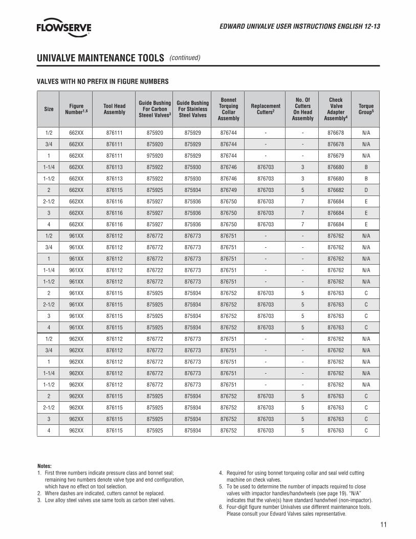
UNIVALVE MAINTENANCE TOOLS (continued)
Size Figure Number1,6
Tool Head Assembly
Guide Bushing For Carbon
Steeel Valves3
Guide Bushing For Stainless Steel Valves
Bonnet Torquing
Collar Assembly
Replacement Cutters2
No. Of Cutters
On Head Assembly
Check Valve
Adapter Assembly4
Torque Group5
1/2 361XX 876111 875920 875929 876744 - - 876678 N/A
3/4 361XX 876111 875920 875929 876744 - - 876678 N/A
1 361XX 876112 975920 875929 876745 - - 876679 N/A
1-1/4 361XX 876113 875922 875930 876746 876703 3 876680 B
1-1/2 361XX 876114 875921 875931 876746 876703 5 876680 A
2 361XX 876115 875924 875933 876747 876703 5 876681 D
2-1/2 361XX 876116 875926 875917 876748 876703 7 876683 E
3 361XX 876116 875926 875917 876748 876703 7 876683 E
4 361XX 876116 875927 875936 876750 876703 7 876684 E
1/2 362XX 876111 875920 875929 876744 - - 876678 N/A
3/4 362XX 876111 875920 875929 876744 - - 876678 N/A
1 362XX 876111 875920 875929 876744 - - 876679 N/A
1-1/4 362XX 876113 875922 875930 876746 876703 3 876680 B
1-1/2 362XX 876113 875922 875930 876746 876703 3 876680 B
2 362XX 876114 875923 875918 876746 876703 5 876681 A
2-1/2 362XX 876115 875925 875934 876749 876703 5 876682 D
3 362XX 876115 875925 875934 876749 876703 5 876682 D
4 362XX 876116 875927 875936 876750 876703 7 876684 E
1/2 661XX 876111 875920 875929 876744 - - 876678 N/A
3/4 661XX 876111 875920 875929 876744 - - 876678 N/A
1 661XX 876112 875920 875929 876745 - - 876679 N/A
1-1/4 661XX 876113 875922 875930 876746 876703 3 876680 B
1-1/2 661XX 876113 875922 875930 876746 876703 3 876680 B
2 661XX 876115 875925 875934 876749 876703 5 876682 D
2-1/2 661XX 876116 875927 875936 876750 876703 7 876684 E
3 661XX 876116 875927 875936 876750 876703 7 876684 E
4 661XX 876116 875927 875936 876750 876703 7 876684 E
VALVES WITH NO PREFIX IN FIGURE NUMBERS
Notes:1. First three numbers indicate pressure class and bonnet seal;
remaining two numbers denote valve type and end configuration, which have no effect on tool selection.
2. Where dashes are indicated, cutters cannot be replaced.3. Low alloy steel valves use same tools as carbon steel valves.
4. Required for using bonnet torqueing collar and seal weld cutting machine on check valves.
5. To be used to determine the number of impacts required to close valves with impactor handles/handwheels (see page 19). “N/A” indicates that the valve(s) have standard handwheel (non-impactor).
6. Four-digit figure number Univalves use different maintenance tools. Please consult your Edward Valves sales representative.
EDWARD UNIVALVE USER INSTRUCTIONS ENGLISH 12-13
11
UNIVALVE MAINTENANCE TOOLS (continued)
Size Figure Number1,6
Tool Head Assembly
Guide Bushing For Carbon
Steeel Valves3
Guide Bushing For Stainless Steel Valves
Bonnet Torquing
Collar Assembly
Replacement Cutters2
No. Of Cutters
On Head Assembly
Check Valve
Adapter Assembly4
Torque Group5
1/2 662XX 876111 875920 875929 876744 - - 876678 N/A
3/4 662XX 876111 875920 875929 876744 - - 876678 N/A
1 662XX 876111 975920 875929 876744 - - 876679 N/A
1-1/4 662XX 876113 875922 875930 876746 876703 3 876680 B
1-1/2 662XX 876113 875922 875930 876746 876703 3 876680 B
2 662XX 876115 875925 875934 876749 876703 5 876682 D
2-1/2 662XX 876116 875927 875936 876750 876703 7 876684 E
3 662XX 876116 875927 875936 876750 876703 7 876684 E
4 662XX 876116 875927 875936 876750 876703 7 876684 E
1/2 961XX 876112 876772 876773 876751 - - 876762 N/A
3/4 961XX 876112 876772 876773 876751 - - 876762 N/A
1 961XX 876112 876772 876773 876751 - - 876762 N/A
1-1/4 961XX 876112 876722 876773 876751 - - 876762 N/A
1-1/2 961XX 876112 876772 876773 876751 - - 876762 N/A
2 961XX 876115 875925 875934 876752 876703 5 876763 C
2-1/2 961XX 876115 875925 875934 876752 876703 5 876763 C
3 961XX 876115 875925 875934 876752 876703 5 876763 C
4 961XX 876115 875925 875934 876752 876703 5 876763 C
1/2 962XX 876112 876772 876773 876751 - - 876762 N/A
3/4 962XX 876112 876772 876773 876751 - - 876762 N/A
1 962XX 876112 876772 876773 876751 - - 876762 N/A
1-1/4 962XX 876112 876772 876773 876751 - - 876762 N/A
1-1/2 962XX 876112 876772 876773 876751 - - 876762 N/A
2 962XX 876115 875925 875934 876752 876703 5 876763 C
2-1/2 962XX 876115 875925 875934 876752 876703 5 876763 C
3 962XX 876115 875925 875934 876752 876703 5 876763 C
4 962XX 876115 875925 875934 876752 876703 5 876763 C
VALVES WITH NO PREFIX IN FIGURE NUMBERS
Notes:1. First three numbers indicate pressure class and bonnet seal;
remaining two numbers denote valve type and end configuration, which have no effect on tool selection.
2. Where dashes are indicated, cutters cannot be replaced.3. Low alloy steel valves use same tools as carbon steel valves.
4. Required for using bonnet torqueing collar and seal weld cutting machine on check valves.
5. To be used to determine the number of impacts required to close valves with impactor handles/handwheels (see page 19). “N/A” indicates that the valve(s) have standard handwheel (non-impactor).
6. Four-digit figure number Univalves use different maintenance tools. Please consult your Edward Valves sales representative.

EDWARD UNIVALVE USER INSTRUCTIONS ENGLISH 12-13
12
UNIVALVE MAINTENANCE TOOLS (continued)
VALVES WITH “B” PREFIX FIGURE NUMBERS
Size Figure Number1,6
Tool Head Assembly
Guide Bushing For Carbon
Steeel Valves3
Guide Bushing For Stainless Steel Valves
Bonnet Torquing
Collar Assembly
Replacement Cutters2
No. Of Cutters
On Head Assembly4
Check Valve
Adapter Assembly
Torque Group5
1/2 B36XXX 876112 499563 499564 876745 - - 166933 N/A
3/4 B36XXX 876112 499563 499564 876745 - - 166933 N/A
1 B36XXX 876112 499563 499564 876745 - - 166933 N/A
1-1/4 B36XXX 876114 875923 494228 876746 876703 5 166934 B
1-1/2 B36XXX 876114 875923 494228 876746 876703 5 166934 B
2 B36XXX 876115 875925 875934 876749 876703 5 166935 D
2-1/2 B36XXX 876116 875927 875936 876749 876703 7 166936 E
3 B36XXX 876116 875927 875936 876749 876703 7 166936 E
4 B36XXX 876116 875927 875936 876748 876703 7 166939 E
1/2 B66XXX 876112 499563 499564 876745 - - 166933 N/A
3/4 B66XYX 876112 499563 499564 876745 - - 166933 N/A
1 B66XXX 876112 499563 499564 876745 - - 166933 N/A
1-1/4 B66XXX 876113 875922 875930 876746 876703 3 166934 A
1-1/2 B66XXX 876113 875922 875930 876746 876703 3 166934 A
2 B66XXX 876115 875925 875934 876749 876703 5 166935 D
2-1/2 B66XYX 876116 875927 875936 876748 876703 7 166939 E
3 B66XXX 876116 875927 875936 876748 876703 7 166939 E
4 B66XXX 876116 875927 875936 876748 876703 7 166939 E
1/2 B96XXX 876112 876772 876773 876746 - - 168554 N/A
3/4 B96XXX 876112 876772 876773 876746 - - 168554 N/A
1 B96XXX 876112 876772 876773 876746 - - 168554 N/A
1-1/4 B96XXX 876112 876772 876773 876746 - - 168554 N/A
1-1/2 B96XXX 876112 876772 876773 876746 - - 168554 N/A
2 B96XXX 876115 875925 875934 876748 876703 5 876683 C
2-1/2 B96XXX 876115 875925 875934 876748 876703 5 876683 C
3 B96XXX 876115 875928 875934 876748 876703 5 876683 C
4 B96XXX 876115 875925 875934 876748 876703 5 876683 C
Notes:1. First three numbers indicate pressure class and bonnet seal;
remaining two numbers denote valve type and end configuration, which have no effect on tool selection.
2. Where dashes are indicated, cutters cannot be replaced.3. Low alloy steel valves use same tools as carbon steel valves.
4. Required for using bonnet torqueing collar and seal weld cutting machine on check valves.
5. To be used to determine the number of impacts required to close valves with impactor handles/handwheels (see page 19). “N/A” indicates that the valve(s) have standard handwheel (non-impactor).
6. Four-digit figure number Univalves use different maintenance tools. Please consult your Edward Valves sales representative.

EDWARD UNIVALVE USER INSTRUCTIONS ENGLISH 12-13
13
UNIVALVE MAINTENANCE TOOLS (continued)
VALVES WITH “C” AND “D” PREFIX FIGURE NUMBERS*
Size Figure Number1,6
Tool Head Assembly
Guide Bushing For Carbon
Steeel Valves3
Guide Bushing For Stainless Steel Valves
Bonnet Torquing
Collar Assembly
Replacement Cutters2
No. Of Cutters
On Head Assembly4
Check Valve
Adapter Assembly
Torque Group5
1/2 X36XXX 876112 499564 499564 876745 - - 166933 N/A
3/4 X36XXX 876112 499564 499564 876745 - - 166933 N/A
1 X36XXX 876112 499564 499564 876745 - - 166933 N/A
1-1/4 X36XXX 876114 494228 494228 876746 876703 5 166934 B
1-1/2 X36XXX 876114 494228 494228 876746 876703 5 166934 B
2 X36XXX 876115 875934 875934 876749 876703 5 166935 D
2-1/2 X36XXX 876116 875936 875936 876749 876703 7 166936 E
3 X36XXX 876116 875936 875936 876749 876703 7 166936 E
4 X36XXX 876116 875936 875936 876748 876703 7 166939 E
1/2 X66XXX 876112 499564 499564 876745 - - 166933 N/A
3/4 X66XXX 876112 499564 499564 876745 - - 166933 N/A
1 X66XXX 876112 499564 499564 876745 - - 166933 N/A
1-1/4 X66XXX 876113 875930 875930 876746 876703 3 166934 A
1-1/2 X66XXX 876113 875930 875930 876746 876703 3 166934 A
2 X66XXX 876115 875934 875934 876749 876703 5 166935 D
2-1/2 X66XXX 876116 875936 875936 876748 876703 7 166939 E
3 X66XXX 876116 875936 875936 876748 876703 7 166939 E
4 X66XXX 876116 875936 875936 876748 876703 7 166939 E
1/2 X96XXX 876112 876773 876773 876746 - - 168554 N/A
3/4 X96XXX 876112 876773 876773 876746 - - 168554 N/A
1 X96XXX 876112 876773 876773 876746 - - 168554 N/A
1-1/4 X96XXX 876112 876773 876773 876746 - - 168554 N/A
1-1/2 X96XXX 876112 876773 876773 876746 - - 168554 N/A
2 X96XXX 876115 875934 875934 876748 876703 5 876683 C
2-1/2 X96XXX 876115 875934 875934 876748 876703 5 876683 C
3 X96XXX 876115 875934 875934 876748 876703 5 876683 C
4 X96XXX 876115 875934 875934 876748 876703 5 876683 C
Notes:1. First three numbers indicate pressure class and bonnet seal;
remaining two numbers denote valve type and end configuration, which have no effect on tool selection.
2. Where dashes are indicated, cutters cannot be replaced.3. Low alloy steel valves use same tools as carbon steel valves.
4. Required for using bonnet torqueing collar and seal weld cutting machine on check valves.
5. To be used to determine the number of impacts required to close valves with impactor handles/handwheels (see page 19). “N/A” indicates that the valve(s) have standard handwheel (non-impactor).
6. Four-digit figure number Univalves use different maintenance tools. Please consult your Edward Valves sales representative.
*Prefix examples: X36220 = C36220 or D36220.

EDWARD UNIVALVE USER INSTRUCTIONS ENGLISH 12-13
14
REASSEMBLY OF UNWELDED BONNET UNIVALVES
GENERAL: Be sure all parts are clean of dirt, rust or scale.
• Always install a new stem-disk assembly into the bonnet if the one is damaged, e.g., the disk seat damaged or stem scratched, worn or pitted. Make sure all dirt is removed from old stems.
• Apply a light coating of a good high-temperature lubricant to the bonnet-body threads, such as Bostik Never-Seez™ – Regular Grade; stainless Univalves should use Nickel Special Nuclear Grade. Do not use excessive amounts, and keep it off the gasket seal faces of unwelded Univalves.
• Next, install a new graphitic gasket seal ring – it should always be replaced – by slipping it onto the bonnet and placing it snugly against the off-set. A light film of oil (not Never-Seez™) helps hold it in place.
• Slip the locking collar over the bonnet from the body end, with the lug toward the body. Install the capscrew and nut on the collar, but do not tighten.*
• Next carefully screw the bonnet and stem-disk assembly into the body, making certain the disk is off the body seat (valve is open). Using the Bonnet Torquing Collar assembly, tighten the threads to the torque shown for unwelded bonnet Univalves.
THIS IS VERY IMPORTANT FOR UNWELDED BONNET UNIVALVES.
• Verify that the bonnet shoulder does not bottom out on the body.
• Rotate the locking collar counterclockwise so the lug is against one of the body lugs. Tighten nut to the torque value for the yoke bolts, as shown in the next column.
• Install the packing if the original is to be replaced. See “Packing Installation,” pg. 16.
• Making sure the stem is clean, apply a light coat of extreme pressure grease, such as American Oil Rycon EP-2 or equivalent on the threads. Screw the yoke onto the stem, then onto the bonnet, turning it down snugly against the bonnet shoulder. Lubricate and then tighten the yoke bolt as follows:
3/8 dia. bolt 16/20 ft-lb 25/30 N-M 7/16 dia. bolt 30/35 ft-lb 45/50 N-M
• Tighten the gland bolts. IMPORTANT: per “Torque Range for Packing Gland Bolts,” pg. 17.
• Install the handwheel or actuator. For safety reasons, make sure the self-locking stem nut is tight on the handwheel valves.
NOTE: Univalves with “B” prefix or no prefix have a different type of locking collar which is installed after the bonnet has been tightened into the body.
REASSEMBLY OF WELDED BONNET UNIVALVES
GENERAL: Be sure all parts are clean of dirt, rust or scale.
• Always install a new stem-disk assembly into the bonnet if the old one is damaged, e.g., the disk seat is damaged or stem scratched/worn or pitted. Make sure all dirt is removed from old stems.
• Class 4500 welded bonnet Univalves (only) should have both the bonnet insert and graphitic gasket seal ring replaced. Do this by removing the stem-disk assembly from the bonnet, placing the new bonnet insert and graphitic gasket seal ring over the stem, then installing the stem back into the bonnet.
• Apply a light coating of a good high-temperature lubricant to the bonnet-body threads, such as Bostik Never-Seez™ Regular Grade; stainless Univalves should use Nickel Special Nuclear Grade. Do not use excessive amounts.
• Next, carefully screw the bonnet and stem-disk assembly into the body, making certain the disk is off the body seat (valve is open). Apply a nominal torque, as specified on pg. 16 for welded bonnet Univalves.
• Seal weld the bonnet; refer to pg. 18.• Install the packing if the original is to be replaced. See
“Packing Installation,” pg. 16.• Making sure the stem is clean, apply a light coat of
extreme pressure grease, such as American Oil Rycon EP-2 or equivalent, on the threads. Screw the yoke onto the stem, then onto the bonnet, turning it down snugly against the bonnet shoulder. Lubricate and then tighten the yoke bolt as follows:
3/8 dia. bolt 16/20 ft-lb 25/30 N-M 7/16 dia. bolt 30/35 ft-lb 45/50 N-M
• Tighten the gland bolts. IMPORTANT: per “Torque Range for Packing Gland Bolts,” pg. 17.
• Install the handwheel or actuator. For safety reasons, make sure the self-locking stem nut is tight on handwheel valves.
REASSEMBLY OF THE UNIVALVE

EDWARD UNIVALVE USER INSTRUCTIONS ENGLISH 12-13
15
REASSEMBLY OF THE UNIVALVE (continued)
UNWELDED UNIVALVE BONNET GASKET TORQUES
*Prefix examples: X36220=B36220, C36220 or D36220.
ft-lb: Bold face numerals are feet-pounds.N-M: Regular face numerals are in newton-meters.
Figure NumberValve Size (No Prefix Figure Numbers)
1/2 3/4 1 1-1/4 1-1/2 2 2-1/2 3 4
36220, 36224
36228, 36264
36268, 36270
36274, 36278
50-6070-80
50-6070-80
50-6070-80
90-105125-145
90-105125-145
140-155190-210
260-290355-395
260-290355-395
400-440545-600
66220, 66224,
66228, 66264
66268, 66270
66274, 66278
50-6070-80
50-6070-80
50-6070-80
90-105125-145
90-105125-145
260-290355-395
400-440545-600
400-440545-600
400-440545-600
96224, 96228
96264, 96268
96274, 96278
110-120150-165
110-120150-165
110-120150-165
110-120150-165
110-120150-165
430-475585-645
430-475585-645
430-475585-645
430-475585-645
Figure Number B, C & D
Valve Size (Prefix B, C & D Figure Number)
1/2 3/4 1 1-1/4 1-1/2 2 2-1/2 3 4
X36220, X36224,
X36228, X36260
X36264, X36268
X36270, X36274
X36278
70-8095-110
70-8095-110
70-8095-110
140-155190-210
140-155190-210
260-290355-395
400-440545-600
400-440545-600
400-440545-600
X66220, X66224
X66228, X66260,
X66264, X66268,
X66270, X66274,
X66278
70-8095-110
70-8095-110
70-8095-110
90-105125-145
90-105125-145
260-290355-395
400-440545-600
400-440545-600
400-440545-600
X96224, X96228
X96264, X96268
X96274, X96278
110-120150-165
110-120150-165
110-120150-165
110-120150-165
110-120150-165
430-475585-645
430-475585-645
430-475585-645
430-475585-645

EDWARD UNIVALVE USER INSTRUCTIONS ENGLISH 12-13
16
GENERAL: Be sure all parts are clean of dirt, rust or scale.
Packing Installation
If the Univalve packing was sealing well and has not been removed, it can be reused. However, if leaking, or if it has been removed from the bonnet, it should be replaced. We recommend packing be purchased from Edward Valves to assure packing with the proper density and corrosion inhibitors is always used.
IMPORTANT: Long service life from modern graphitic packing requires that adequate preloads be applied when repacking.
• All parts should be clean and not scored or pitted, especially the stem.
• The stem, disk and bonnet should be in the valve prior to installing the new packing.
• Position split packing with the ends of adjacent rings rotated 90°.
• Standard packing: – Top Ring: Braided Carbon Fiber Ring Note: Class 4500 valves use two (2) top rings
– Center Ring: Flexible Graphite Ring – Bottom Ring: Same as top (Class 4500 has only one [1] ring on bottom).
• Clean and lubricate the gland screws.• Tamp the packing down by hand using the gland.• IMPORTANT: Apply the recommended torque to
the gland bolts evenly without cocking the gland. See pg. 15 for torques.
• Stroke the stem and then recheck the torque on the gland bolts.
REASSEMBLY OF THE UNIVALVE (continued)
Packing Chamber Schematic
ft-lb: Bold face numerals are feet-pounds.N-M: Regular face numerals are in newton-meters.
Figure NumberValve Size
1/2 3/4 1 1-1/4 1-1/2 2 2-1/2 3 4
All 5070
100135
WELDED UNIVALVE BONNET TORQUES

EDWARD UNIVALVE USER INSTRUCTIONS ENGLISH 12-13
17
REASSEMBLY OF THE UNIVALVE (continued)
TORQUE RANGE FOR PACKING GLAND BOLTS
*Prefix examples: X36220=B36220, C36220 or D36220.
ft-lb: Bold face numerals are feet-pounds.N-M: Regular face numerals are in newton-meters.
Figure NumberValve Size (No Prefix Figure Numbers)
1/2 3/4 1 1-1/4 1-1/2 2 2-1/2 3 4
36120, 36124,
36128, 36164,
36168
8-1311-18
8-1311-18
10-1514-20
19-2426-33
18-2324-31
23-2831-38
26-3135-42
26-3135-42
37-4250-57
36220, 36224
36228, 36264,
36368
8-1311-18
8-1311-18
8-1311-18
19-2426-33
19-2426-33
18-2324-31
27-3237-43
27-3237-43
37-4250-57
66120, 66124,
66128, 66164,
66168
9-1412-19
9-1412-19
11-1615-22
21-2629-35
21-2629-35
30-3541-47
41-4756-64
41-4756-64
41-4756-64
66220, 66224,
66228, 66264,
66268
9-1412-19
9-1412-19
9-1412-19
21-2629-35
21-2629-35
30-3541-47
41-4756-64
41-4756-64
41-4756-64
96124, 96128,
96164, 9616818-2324-31
18-2324-31
18-2324-31
25-3034-41
25-3034-41
63-7285-98
63-7285-98
63-7285-98
63-7285-98
96224, 96228,
96264, 9626818-2324-31
18-2324-31
18-2324-31
25-3034-41
25-3034-41
63-7285-98
63-7285-98
63-7285-98
63-7285-98
Figure Number B, C & D*
Valve Size (Prefix B, C & D Figure Number)
1/2 3/4 1 1-1/4 1-1/2 2 2-1/2 3 4
X36120, X36124,
X36128, X36160,
X36164, X36168,
X36220, X36224,
X36228, X36264,
X36268
10-1514-20
10-1514-20
10-1514-20
21-2629-35
21-2629-35
33-3845-52
37-4250-57
37-4250-57
37-4250-57
X66120, X66124,
X66128, X66160,
X66164, X66168,
X66220, X66224
X66228, X66264,
X66268
13-1818-24
13-1818-24
13-1818-24
21-2629-35
21-2629-35
38-4352-58
41-4756-64
41-4756-64
41-4756-64
X96124, X96128,
X96164, X96168,
X96224, X96228,
X96264, X96268
22-2730-37
22-2730-37
22-2730-37
22-2730-37
22-2730-37
63-7285-98
63-7285-98
63-7285-98
63-7285-98

EDWARD UNIVALVE USER INSTRUCTIONS ENGLISH 12-13
18
A105 AND F22 UNIVALVES
Seal weld of A105 (Carbon) and F22 (Low-alloy) Univalves are made using a “Fillet” weld.
RE-WELDING
• To allow welding gases to escape, do not fully seat or backseat valve.
• Weld surfaces shall be clean and dry.• Preheat to 300°F – 400°F.• Weld A105 Univalves with SFA 5.1 E7018 electrodes and
F22 Univalves with SFA 5.5 E9018-B3 electrodes.• Deposit weld metal to meet dimensions shown in table
below.
REPLACING THE SEAL WELD UNIVALVES
Univalve Size Min. Leg Min. Throat
Min. Passes
1-1/2 and smaller 3-16 1/8 2
2 (except Class 4500) 1/4 3/16 2
2 (Class 4500 and valves over 2) 3/8 1/4 2
JOINT
Seal welds of F316, F316L and F347 (Stainless Steel) Univalves are made using a “Canopy” weld.
• Univalves should be prepared for the Joint design shown below.
RE-WELDING
• To allow welding gases to escape, do not fully seat or backseat the valve.
• Weld surfaces shall be clean and dry.• Preheat to 70°F – 150°F.• Maintain an interpass temperature of 350°F maximum.• Weld F316 Univalves using SFA 5.9 ER316L bare rod,
F316L Univalves using SFA 5.9 ER308L bare rod and F347 Univalves using SFA 5.9 ER347 bare rod.
• Deposit weld metal to meet dimensions shown in sketch below.
F316 AND F347 UNIVALVES

EDWARD UNIVALVE USER INSTRUCTIONS ENGLISH 12-13
19
OPERATIONAL RECOMMENDATIONS
RECOMMENDED CLOSING TORQUES
To assure long seat life and seat tightness, it is very important to close the Univalve with enough seat stress/stem load.
The torques in this table should be applied when closing against the maximum (100°F) valve pressure. The impactor handle/handwheel performance chart on pg. 20 will achieve these stem loads.
Overtorquing can, on the other hand, damage seats and bend stems, so torques greatly in excess of these should not be applied.
Torques are for valves with stem packing tightened – see page 17.
Figure NumberAll Valves With Five-Digit Figure Numbers
1/2 3/4 1 1-1/4 1-1/2 2 2-1/2 3 4
36120, 36124,
36128, 36160
36164, 36168
30 30 30 95 95 155 275 275 275
36220, 36224,
36228, 36260,
36264, 36268
30 30 30 95 95 155 275 275 275
66120, 66124,
66128, 66160,
66164, 66168
45 45 45 85 85 230 395 395 395
66220, 66224,
66228, 66260,
66264, 66268
45 45 45 85 85 230 395 395 395
96124, 96128,
96164, 9616870 70 70 70 70 350 350 350 350
96224, 96228,
96264, 9626870 70 70 70 70 350 350 350 350
MINIMUM TORQUE FOR CLOSING VALVES — FT-LB ON MAIN SEAT (Do Not Apply This Load to Backseats.)

EDWARD UNIVALVE USER INSTRUCTIONS ENGLISH 12-13
20
Correct Use of Impactor Handles/Handwheels to Close Applicable Univalves (Sizes 1-1/4 Through 4)
IMPACTOR HANDLE/HANDWHEELS
Impactor handle/handwheels increase the closing effectiveness and eliminate the need for cheater bars.
Impactor handles/handwheels used on Edward Univalves have the proven ability to achieve tight sealing, eliminating leakage past the seats.They allow the recommended stem loads on pg. 19 to be easily achieved.
Since they are smaller in diameter than standard handwheels, they must be impacted multiple times to develop the required torque. The number of impacts required depends upon the size of the handle/handwheel, the stem and seat size, and the differential pressure against which the valve is being closed.
The values listed in the chart below are based on a standard rating for the ability of plant personnel to accelerate the handle/handwheel against the the stem adaptor. In addition, these values assume that all parts are in good working order (no binding or heavy dirt build-up on stem). The figures given represent the minimum number of required impacts, and exceeding them will not damage valves. Failure to close these valves tightly, on the other hand, will cause leakage, with resulting degradation of the sealing surfaces over time.
OPERATIONAL RECOMMENDATIONS (continued)
IMPACTOR HANDLE/HANDWHEEL PERFORMANCE CHART
Maximum Shut-Off Pressure < 1000 PSIGMaximum Shut-Off Pressure < 1500 PSIGMaximum Shut-Off Pressure < 2000 PSIGMaximum Shut-Off Pressure < 2500 PSIG
Maximum Shut-Off Pressure < 3000 PSIGMaximum Shut-Off Pressure < 3500 PSIGMaximum Shut-Off Pressure < 4000 PSIG3
1.) See pages 10–13 for identification of torque groups A through E.2.) Number of impacts listed are “minimum” values for corresponding shut-off pressure range.3.) For shut-off pressures greater than 4000 PSIG, double the number of impacts recommended at 4000 PSIG for the applicable valve group.
22
20
18
16
14
12
10
8
6
4
2
0
22
20
18
16
14
12
10
8
6
4
2
0Torque Group A1 Torque Group B1 Torque Group C 1 Torque Group D1 Torque Group E 1
Num
ber o
f Im
pact
s Re
quire
d fo
r Tig
ht C
losu
re2
Impactor

EDWARD UNIVALVE USER INSTRUCTIONS ENGLISH 12-13
21
WARNING
The Edward Univalve® is not provided with a pressure relief device. A pressure relief device must be provided elsewhere in the piping system to prevent the piping system pressure from exceeding the maximum rated pressure of the Univalve.
CONVERTING UNIVALVES
Welded bonnet carbon steel and F22 Univalves, Class 1690 and 2680, can be converted to unwelded types by removing the seal weld and bonnet, and adding a graphitic gasket and a locking collar to assure the bonnet will remain locked to the body. Torque the bonnet per pg. 15.
Unwelded bonnet carbon steel and F22 Univalves, Class 1690 and 2680, can be converted to welded types by adding a seal weld. Edward Valves does not recommend adding a seal weld to Univalves with the graphitic bonnet gasket installed, because of the possibility of over-pressurizing the threaded region with fluid trapped between the seal weld and graphitic gasket; remove the gasket before welding.
WELDING UNIVALVES INTO PIPING
WeIding is outside the scope of this manual, but Edward recommends you consult the appropriate welding procedure in ASME/ANSI B31, or whatever other codes apply to your system. When welding Univalves into piping, make sure there is no foreign material on the seat joint, then close the valve tightly to approximately 50% of the torque values in the chart on pg. 19, to avoid distorting the seats.
During subsequent stress relief of the welds, leave the valve closed to avoid distorting the valve seat. Also, during stress relief, assure that the valve upperstructure is not overheated. After welding, open the valve and flush the line to clean out all foreign matter.
PIPING SUPPORT
Piping should be supported sufficiently to preclude excessive end loads on the valve.
VALVE INSTALLATION GUIDELINES
Except as noted below, Univalve stop valves and check valves with springs can be installed in any position. Installed positions with the valve cover or bonnet below horizontal, where dirt and scale can accumulate in the valve neck, should be avoided.
For optimum performance, the orientation limits shown in Figures 1 and 2 should be observed, even for spring-loaded check valves.
The orientation limits shown in Figures 1 and 2 must not be exceeded for Univalve Stop-Check valves and Check valves without springs. The limitations given for line inclination and bonnet roll angle should not be combined.
All Check and Stop-Check valves should be installed with 10 or more diameters of straight pipe upstream of the valve to minimize flow disturbances. For additional information, refer to the “Technical” section of the Flowserve-Edward catalog FCD EVENCT0001 or FCD EVENCT0002.
GENERAL INFORMATION
Figure 1 45° Inclined Bonnet Piston-Lift Check Valves Maximum Check Valve Orientation Limits
Figure 2Angle Piston-Lift Check Valves Orientation Limits

EDWARD UNIVALVE USER INSTRUCTIONS ENGLISH 12-13
22
NOTES ON VALVE OPERATION
Valves equipped with electric motor actuators have special tags attached which indicate the correct torque switch setting for the valve. Exceeding these torque switch settings can cause damage to the valve.
Never use an electric motor actuator to backseat a valve. This can result in damage to the valve stem and bonnet backseat.
NOTES ON VALVE MAINTENANCE
When replacing the bonnet gasket in the unwelded Univalve, follow the torque requirements on page 15 closely. Failure to torque the gasket properly will result in gasket failure.
When replacing the valve stem packing, never machine the packing chamber oversize. This will result in blowout of the packing.
LUBRICATION
In order to obtain full service life, valves require periodic lubrication of the stem threads. Exposed threads should be wiped clean of old grease and accumulated dirt and fresh lubricant applied. This is most effectively done with the valve in the closed position.
For valves that see frequent operation, such as motor actuated, the lubricant should be replenished every three months. If extreme service conditions dictate, a more frequent re-lube schedule is recommended. Motor actuated valves have a lubricant fitting at the yoke flange.
The recommended lubricant for all stem threads is Rykon EP #2, manufactured by the American Oil Company. This is an extreme pressure, extreme temperature lubricant of high quality. For vaIves that are operated infrequently, relubrication should be at least once a year.
GENERAL INFORMATION (continued)
SEAT AND DISK JOINT LEAKS
A leak existing between the seat and disk of a closed valve might be indicated by one of the following: a definite pressure loss in the high-pressure side of the valve; continued flow through an inspection drain on the low-pressure side; or, in hot water or steam lines, a downstream pipe that remains hot beyond the usual length of time and conductivity range.
Such a leak may be the result of closing on dirt, scale or other foreign matter in the line. It may also develop because of the operator’s failure to close the valve tightly. An increased velocity is imparted to a flow forced through a very small opening. This increased velocity subsequently gives rise to the “cutting” of both disk and seat, particularly by particles of line scale or rust in suspension or normal solids in solution. In spite of the fact that the hard surfaced material on the seat and disk is corrosion and erosion resistant, grooves, pit marks, or other surface irregularities may be formed on the seat and disk joint surfaces when the disk is closed against a foreign body on the seat. This sometimes occurs during the initial startup of a piping system.
Leakage of steam through a valve which is badly steam cut has a whistling or sonorous sound. If the valve is only slightly steam cut, however, leakage is identified by subdued gurgling or weakly popping sounds. These sounds can be heard through a stethoscope or by placing one end of a stick against the valve body while holding the other end between the teeth, with hands over the ears.
HOW TO ORDER PARTS
During normal working hours, call 800/225-6989 or 919/832-0525. To assure the correct parts for your Univalve, include the valve size, the figure number ñ including any prefix and/or suffixes and if available, the B/M number. All nuclear valves require the B/M number to properly identify your Univalve.
This information is located on the valve nameplate. The nameplate is attached to a yoke leg via a cable. If the nameplate is inaccessible, you can use your Edward sales drawing; please include the drawing number as well.

EDWARD UNIVALVE USER INSTRUCTIONS ENGLISH 12-13
23
NOTES

flowserve.com
For more information about Flowserve Corporation, contact www.flowserve.com or call USA 1-800-225-6989.
FCD EVENIM2000-02 (E) 12/13 © 2013 Flowserve Corporation.
Flowserve Corporation has established industry leadership in the design and manufacture of its products. When properly selected, this Flowserve product is designed to perform its intended function safely during its useful life. However, the purchaser or user of Flowserve products should be aware that Flowserve products might be used in numerous applications under a wide variety of industrial service conditions. Although Flowserve can (and often does) provide general guidelines, it cannot provide specific data and warnings for all possible applications. The purchaser/user must therefore assume the ultimate responsibility for the proper sizing and selection, installation, operation, and maintenance of Flowserve products. The purchaser/user should read and understand the Installation Operation Maintenance (IOM) instructions included with the product, and train its employees and contractors in the safe use of Flowserve products in connection with the specific application.
While the information and specifications contained in this literature are believed to be accurate, they are supplied for informative purposes only and should not be considered certified or as a guarantee of satisfactory results by reliance thereon. Nothing contained herein is to be construed as a warranty or guarantee, express or implied, regarding any matter with respect to this product. Because Flowserve is continually improving and upgrading its product design, the specifications, dimensions and information contained herein are subject to change without notice. Should any question arise concerning these provisions, the purchaser/user should contact Flowserve Corporation at any one of its worldwide operations or offices.
© 2013 Flowserve Corporation, Irving, Texas, USA. Flowserve is a registered trademark of Flowserve Corporation.
FLOWSERVE CORPORATION FLOW CONTROL DIVISIONEdward Valves1900 South Saunders StreetRaleigh, NC 27603 USA
Toll-Free Telephone Service(U.S. and Canada)Day: 800 225 6989
After-Hours Customer Service1 800 543 3927
U.S. Sales OfficesPhone: 919 832 0525Fax: 919 831 3369
Visit Our Websitewww.edwardvalves.com