user instructions - flowserve...in case of long-term storage (more than 4 months), additionally...
TRANSCRIPT

Experience In Motion
USER INSTRUCTIONS
InstallationOperation
Maintenance
Mechanical and Hydraulic Manual OverridesFCD LFENIM0004-00-AQ – (05/15)
Mechanical and Hydraulic Overrides FCD LFENIM0004-00-AQ – 05/15
2
Contents1 Standard Information 4
1.1 Using Flowserve Valves, Actuators & Accessories Correctly 41.2 Terms Concerning Safety 41.3 Protective Clothing 41.4 Qualified Personnel 51.5 Other General Requirements for In-Plant Installation 51.6 Spare Parts 51.7 Service/Repair 51.8 Storage 61.9 Valve and Actuator Variations 61.10 Unpacking 6
2 Mechanical Manual 72.1 Enclosed Jackscrew Manual Override (-JS) 7
2.1.1 Installation 82.1.2 Operation – Enclosed Jackscrew Override Installed on Single-Acting Actuator 82.1.3 Operation – Enclosed Jackscrew Override Installed on Double-Acting Actuator 9
2.2 Not Enclosed Jackscrew Manual Override (-JL) 92.2.1 Installation 112.2.2 Operation – Not Enclosed Jackscrew Override Installed on LPS/LPC Single-Acting Actuator 122.2.3 Operation – Not Enclosed Jackscrew Override Installed on Double-Acting LPC Actuator 13
2.3 Bevel Gear Manual Overrides (-BG) 142.3.1 Installation 142.3.2 Operation – Bevel Gear Override Installed on LPS Single-Acting Actuator 15
3 Hydraulic Manual Overrides 163.1 Hydraulic Hand Pump Manual Override (-HP) 16
3.1.1 Installation 173.1.2 Operation – Hydraulic Hand Pump Override Installed on LPS Single-Acting Actuator 173.1.3 Operation – Hydraulic Hand Pump Override Installed on LPS Double-Acting Actuator 193.1.4. Operation – Hydraulic Hand Pump Override Installed on LHS Single Acting Actuator 213.1.5 Operation – Hydraulic Hand Pump Override Installed on LHS Double-Acting Actuator 22
4 Maintenance Instructions 244.1 Service Kits 25
3
Mechanical and Hydraulic Overrides FCD LFENIM0004-00-AQ – 05/15
flowserve.com
FiguresFigure 1 – Enclosed Jackscrew Manual Override for Double-Acting Actuators (left) and for Single-Acting Actuators (right) 7Figure 2 – LPS Single-Acting with Enclosed Jackscrew Override 8Figure 3 – LPS Double-Acting with Enclosed Jackscrew Override (declutchable) 9Figure 4 – Detail of LPS Double-Acting with Enclosed Jackscrew Override (declutchable) 10Figure 5 – Not Enclosed Jackscrew Manual Override 11Figure 6 – LPS/LPC Single-Acting with Not Enclosed Jackscrew Override 12Figure 7 – LPC Double-Acting with Not Enclosed Jackscrew Override 13Figure 8 – Bevel Gear Manual Override 14Figure 9 – LPS Single-Acting with Bevel Gear Override 15Figure 10 – Hydraulic Hand Pump Manual Override 16Figure 11 – Hydraulic Hand Pump Manual Override Installed on Single-Acting actuator 17Figure 12 – Hydraulic Diagram LPS Single-Acting Actuator with Hydraulic Override 18Figure 13 – Details of Hydraulic Hand Pump Manual Override for Single-Acting Actuator 19Figure 14 – Hydraulic Hand Pump Manual Override Installed on Double-Acting Actuator 19Figure 15 – Hydraulic Diagram of LPS Double-Acting Actuator with Hydraulic Override 20Figure 16 – Details of Hydraulic Hand Pump Manual Override for Double-Acting Actuator 20Figure 17 – Hydraulic Hand Pump Manual Override Installed on LHS Single Acting Actuator 21Figure 18 – Hydraulic Diagram of Manual Override for LHS Single Acting 22Figure 19 – Hydraulic Hand Pump Manual Override installed on LHS Single Acting Actuator 22Figure 20 – Hydraulic Diagram of Manual Override for LHS Double Acting 23Figure 21 – Detail of Not-Enclosed Jackscrew and Hand Pump Assembly 24
TablesTable 1 – Spare Parts of Enclosed Jack Screw Manual Override Installed on Single-Acting Actuator 25Table 2 – Spare Parts of Enclosed Jack Screw (declutchable) Manual Override Installed on Double-Acting Actuator 25Table 3 – Spare Parts of Not Enclosed Jack Screw Manual Override 26Table 4 – Spare Parts of Bevel Gear Manual Override 26Table 5 – Spare Parts of Hydraulic Manual Override: Hydraulic Cylinder Assembly 27Table 6 – Spare Parts of Hydraulic Manual Override: Hydraulic Pump Assembly 27
Mechanical and Hydraulic Overrides FCD LFENIM0004-00-AQ – 05/15
4
1 Standard Information
1.1 Using Flowserve Valves, Actuators and Accessories Correctly The following instructions are designed to assist in unpacking, installing and performing maintenance as required on Flowserve mechanical and hydraulic overrides. Product users and maintenance personnel should thoroughly review this bulletin prior to installing, operating or performing any maintenance.
In most cases Flowserve mechanical and hydraulic overrides are designed for specific applications with regard to pressure, tempera-ture and media. For this reason they should not be used in other applications without first contacting the manufacturer. This manual shall be used in conjunction with any other instruction, document, checklist with the actuator the accessories are installed onto, also related to single equipment or parts of actuator itself.
1.2 Terms Concerning SafetyThe safety terms DANGER, WARNING, CAUTION and NOTE are used in these instructions to highlight particular dangers and/or to provide additional information on aspects that may not be readily apparent.
c DANGER: indicates that death, severe personal injury and/or substantial property damage will occur if proper precautions are not taken.
a WARNING: indicates that death, severe personal injury and/or substantial property damage can occur if proper precautions are not taken.
CAUTION: indicates that minor personal injury and/or property damage can occur if proper precautions are not taken.
NOTE: indicates and provides additional technical information, which may not be obvious, even to qualified personnel.
Compliance with all other notes regarding transport, assembly, operation and maintenance and with regard to technical documen-tation (e.g., in the operating instruction, product documentation or on the product itself) is essential, in order to avoid conditions or occurrences which might directly or indirectly cause severe personal injury or property damage.
1.3 Protective ClothingFlowserve products are often used in dangerous applications (e.g., extremely high pressures, flammable, combustible, toxic or corrosive media). When performing service, inspection, or repair operations, always ensure that the valve and actuator are depressurized and that the valve has been cleaned and is free from harmful substances. In such cases, pay particular attention to personal protection equipment (protective clothing, gloves, glasses, etc.).
5
Mechanical and Hydraulic Overrides FCD LFENIM0004-00-AQ – 05/15
flowserve.com
1.4 Qualified PersonnelOnly Qualified Personnel should perform installation, operation or maintenance activities. Qualified personnel are people who, because of their training, experience, instruction and their knowledge of relevant standards, specifications, accident prevention regulations, and operating conditions, have been authorized by those responsible for the safety of the plant and its employees to perform the necessary work and who can recognize and avoid possible dangers.
1.5 Other General Requirements for In-Plant Installation• Pipelines must be correctly aligned to ensure that the valve is not fitted under tension.
• If not expressly agreed, fire protection is not supplied along with the actuator, and it must be provided by user.
1.6 Spare PartsUse only Flowserve brand original spare parts. Flowserve cannot accept responsibility for any damages that occur from using spare parts or fastening materials from other manufacturers. If Flowserve products (especially sealing materials) have been stored for long periods (more than 4 months), check for corrosion or deterioration before using these products.
1.7 Service/RepairTo avoid injury to personnel or damage to products, safety terms must be strictly adhered to. Modifying this product, substituting non-OEM parts, or using maintenance procedures other than outlined in this instruction could drastically affect performance and be hazardous to personnel and equipment, and may void existing warranties.
Between actuator and valve there are moving parts. To avoid injury, Flowserve provides pinch-point-protection in the form of cover plates, especially where side-mounted positioners are fitted. These protections are according to Machine Directive 2006/42/EC recommendations. If these plates are removed for inspection, service or repair special attention is required. After completing work the cover plates must be refitted.
In addition to the operating instructions and the obligatory accident prevention directives valid in the country of use, all recognized regulations for safety and good engineering practices must be followed.
a WARNING: Before products are returned to Flowserve for repair or service, Flowserve must be provided with a certificate which confirms that the product has been decontaminated and is clean. Flowserve will not accept deliveries if a certificate has not been provided (a form can be obtained from Flowserve).
Mechanical and Hydraulic Overrides FCD LFENIM0004-00-AQ – 05/15
6
1.8 StorageIn many cases Flowserve products are manufactured from stainless steel. Products not manufactured from stainless steel are typically provided with an epoxy resin coating or with other painting systems agreed with the customer. This means that Flowserve products are well protected from corrosion. Nevertheless, in order to maintain good working conditions and a good finish until the actuator and its accessories are installed is installed on the plant, it is necessary to follow a few rules during the storage period:
1. Flowserve products must be stored in a clean, dry environment.
2. Ensure that plastic caps are fitted to protect the pneumatic/hydraulic connections and the cable entries, to prevent the ingress of foreign materials. These caps should not be removed until the product is actually mounted into the system.
3. If the storage is outdoor, or if long-term storage (more than 4 months) is necessary, the plastic protection plugs must be replaced by metal plugs, because the plastic plugs are not weather-proof, whereas the metal ones guarantee a weather-proof protection.
4. The actuator, with its mechanical and hydraulic overrides, must be placed on a wooden pallet in order to not damage the coupling base and to prevent other surfaces from resting on the ground.
In case of long-term storage (more than 4 months), additionally perform the following measures:
a. Coat the coupling parts (spool piece base, flanges, bushings, joints) with protective oil or grease.
b. If possible, blank off the spool piece base flange by a protection disk.
c. Provide a tarpaulin cover or some other means of protection, especially if the storage is outdoor.
d. It is important to periodically operate the actuator and its accessories.
1.9 Valve and Actuator VariationsThese instructions cannot claim to cover all details of all possible product variations, nor can they provide information for every possible example of installation, operation or maintenance. If there are any uncertainties in this respect, particularly in the event of missing product-related information, clarification must be obtained via the appropriate Flowserve sales office.
1.10 Unpacking1. Each delivery includes a packing slip. When unpacking, check all delivered actuators and accessories using this packing slip.
2. Report transport damage to the carrier immediately.
3. In case of discrepancies, contact your nearest Flowserve location.
4. If necessary, retouch minor damages to the paint coating which may have occurred during transport or storage.
7
Mechanical and Hydraulic Overrides FCD LFENIM0004-00-AQ – 05/15
flowserve.com
2 Mechanical Manual Overrides
Mechanical Manual Overrides on LFPS heavy duty and compact actuators provide an economical and durable method for manually operating the actuators. LFPS Mechanical Overrides are designed in accordance with EN 12570 Standard. The manual force to operate the actuator shall not exceed the values stated in EN 12570, when measured at the outermost point of the handwheel.
LFPS Mechanical Manual Overrides are available in the following versions:
• Enclosed Jackscrew (-JS)
• Not Enclosed Jackscrew (-JL)
• Bevel gear (-BG)
They are designed and standardized depending on the Actuators series, however special versions are available upon request.
a CAUTION: prior to operating an actuator by means of manual overrides, be sure to remove the pressure inside the cylinder and that the cylinder has been vented to atmosphere through the venting ports. Ensure that all vent valves are in vent position. The number of vent valves varies by actuator and control schematic types.
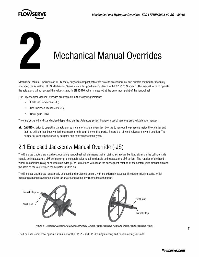
2.1 Enclosed Jackscrew Manual Override (-JS) The Enclosed Jackscrew is a direct operating handwheel, which means that a rotating screw can be fitted either on the cylinder side (single-acting actuators LPS series) or on the scotch-yoke housing (double-acting actuators LPS series). The rotation of the hand-wheel in clockwise (CW) or counterclockwise (CCW) directions will cause the consequent rotation of the scotch-yoke mechanism and the stem of the valve which the actuator is fitted on.
The Enclosed Jackscrew has a totally enclosed and protected design, with no externally exposed threads or moving parts, which makes this manual override suitable for severe and saline environmental conditions.
Figure 1 – Enclosed Jackscrew Manual Override for Double-Acting Actuators (left) and Single-Acting Actuators (right)
The Enclosed Jackscrew option is available for the LPS-15 and LPS-20 single-acting and double-acting versions.
Travel Stop
Seal Nut
Travel Stop
Seal Nut
Mechanical and Hydraulic Overrides FCD LFENIM0004-00-AQ – 05/15
8
2.1.1 Installation - Travel-Stop Bolts Adjustment Enclosed Jackscrew Override Installed on Single and Double Acting Actuators
All actuated valves require accurate travel-stop adjustments at both ends of the stroke to obtain optimum performance and valve seat life. Adjust the travel-stop bolts of the actuator for the proper open and close valve positions, according to Flowserve valve manufacturer’s recommendations.
The Enclosed Jackscrew manual override (-JS) has a travel-stop adjustment in one direction: valve open direction (in double-acting and single acting fail-open) or valve close direction (in single-acting fail close). The travel stop adjustment in the opposite direction must be performed in accordance with the IOM of the actuator.
The +/- 5 degree adjustment feature provides shaft rotation from 80 to 100 degrees overall.
The adjustment of the travel-stops is performed in accordance with the following steps:
2.1.1.1 Loosen the seal nut with a proper wrench (Figure 1).
2.1.1.2 While keeping the seal nut stationary, screw or un-screw the travel-stop (Figure 1) bolt using a proper Allen key.
2.1.1.3 Tighten the seal nut.
2.1.1.4 Pneumatically stroke the actuator several times to assure proper operation. The stem adaptor should not bind during operation. If the actuator is equipped with limit switches, positioners or other accessories, adjust them at this time according to their specific installation manuals.
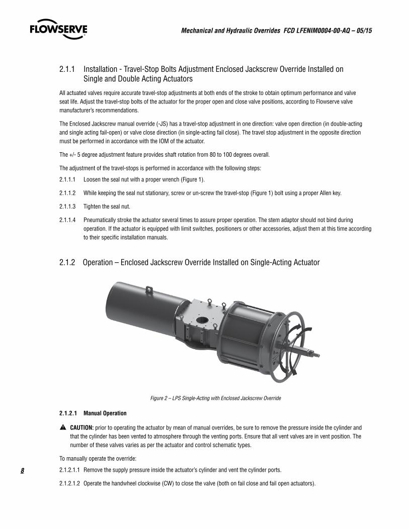
2.1.2 Operation – Enclosed Jackscrew Override Installed on Single-Acting Actuator
Figure 2 – LPS Single-Acting with Enclosed Jackscrew Override
2.1.2.1 Manual Operation
a CAUTION: prior to operating the actuator by mean of manual overrides, be sure to remove the pressure inside the cylinder and that the cylinder has been vented to atmosphere through the venting ports. Ensure that all vent valves are in vent position. The number of these valves varies as per the actuator and control schematic types.
To manually operate the override:
2.1.2.1.1 Remove the supply pressure inside the actuator’s cylinder and vent the cylinder ports.
2.1.2.1.2 Operate the handwheel clockwise (CW) to close the valve (both on fail close and fail open actuators).
9
Mechanical and Hydraulic Overrides FCD LFENIM0004-00-AQ – 05/15
flowserve.com
2.1.2.1.3 Operate the handwheel counterclockwise (CCW) to open the valve (both on fail close and fail open actuators).
NOTE: The spring constantly loads the screw and it returns the actuator to fail-safe position when the jackscrew is retracted (rotating clockwise (CW) on a fail close actuator and rotating counterclockwise (CCW) on a fail open actuator).
2.1.2.2 Restoring Automatic Operation
To restore the automatic operation:
2.1.2.2.1 Operate the handwheel in order to completely retract the jackscrew (rotating clockwise (CW) on a fail close actuator and rotating counterclockwise (CCW) on a fail open actuator) and lock the position with the safety lock1.
2.1.2.2.2 Restore the supply pressure inside the actuator’s cylinder.
2.1.2.2.3 Operate actuator normally with supply pressure.
2.1.2.2.4 Check that the actuator is able to reach the fully close position in case of fail close actuator or the fully open position in case of fail open actuator. It is possible to check the fully-stroked position by viewing the position indicator or limit switches, if fitted. If the actuator is not able to fully stroke in fail-safe direction, verify that the jackscrew has been totally retracted, rotating it as described in step 2.1.2.2.1.
1 The safety lock is only available upon request. Please contact your local Flowserve Limitorque Representative for more information.
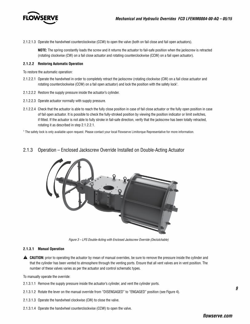
2.1.3 Operation – Enclosed Jackscrew Override Installed on Double-Acting Actuator
Figure 3 – LPS Double-Acting with Enclosed Jackscrew Override (Declutchable)
2.1.3.1 Manual Operation
a CAUTION: prior to operating the actuator by mean of manual overrides, be sure to remove the pressure inside the cylinder and that the cylinder has been vented to atmosphere through the venting ports. Ensure that all vent valves are in vent position. The number of these valves varies as per the actuator and control schematic types.
To manually operate the override:
2.1.3.1.1 Remove the supply pressure inside the actuator’s cylinder, and vent the cylinder ports.
2.1.3.1.2 Rotate the lever on the manual override from “DISENGAGED” to “ENGAGED” position (see Figure 4).
2.1.3.1.3 Operate the handwheel clockwise (CW) to close the valve.
2.1.3.1.4 Operate the handwheel counterclockwise (CCW) to open the valve.
Mechanical and Hydraulic Overrides FCD LFENIM0004-00-AQ – 05/15
10
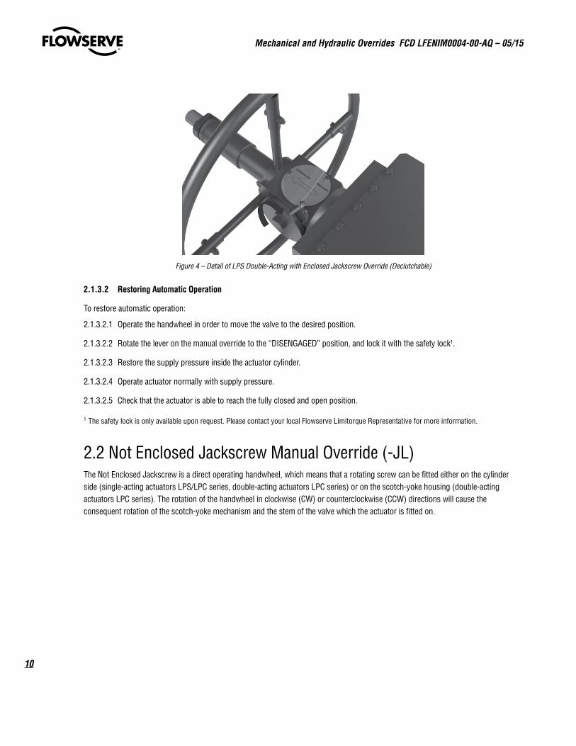
Figure 4 – Detail of LPS Double-Acting with Enclosed Jackscrew Override (Declutchable)
2.1.3.2 Restoring Automatic Operation
To restore automatic operation:
2.1.3.2.1 Operate the handwheel in order to move the valve to the desired position.
2.1.3.2.2 Rotate the lever on the manual override to the “DISENGAGED” position, and lock it with the safety lock1.
2.1.3.2.3 Restore the supply pressure inside the actuator cylinder.
2.1.3.2.4 Operate actuator normally with supply pressure.
2.1.3.2.5 Check that the actuator is able to reach the fully closed and open position.
1 The safety lock is only available upon request. Please contact your local Flowserve Limitorque Representative for more information.
2.2 Not Enclosed Jackscrew Manual Override (-JL) The Not Enclosed Jackscrew is a direct operating handwheel, which means that a rotating screw can be fitted either on the cylinder side (single-acting actuators LPS/LPC series, double-acting actuators LPC series) or on the scotch-yoke housing (double-acting actuators LPC series). The rotation of the handwheel in clockwise (CW) or counterclockwise (CCW) directions will cause the consequent rotation of the scotch-yoke mechanism and the stem of the valve which the actuator is fitted on.
11
Mechanical and Hydraulic Overrides FCD LFENIM0004-00-AQ – 05/15
flowserve.com
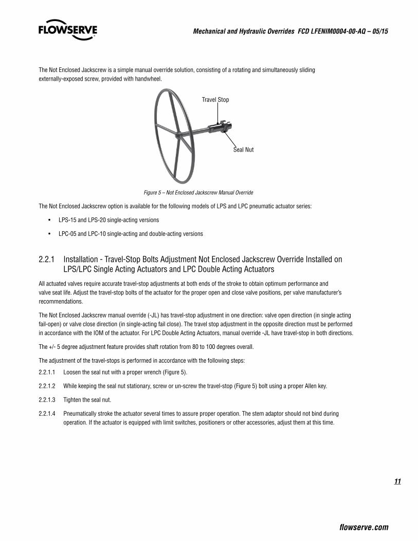
The Not Enclosed Jackscrew is a simple manual override solution, consisting of a rotating and simultaneously sliding externally-exposed screw, provided with handwheel.
Figure 5 – Not Enclosed Jackscrew Manual Override
The Not Enclosed Jackscrew option is available for the following models of LPS and LPC pneumatic actuator series:
• LPS-15 and LPS-20 single-acting versions
• LPC-05 and LPC-10 single-acting and double-acting versions
2.2.1 Installation - Travel-Stop Bolts Adjustment Not Enclosed Jackscrew Override Installed on LPS/LPC Single Acting Actuators and LPC Double Acting Actuators
All actuated valves require accurate travel-stop adjustments at both ends of the stroke to obtain optimum performance and valve seat life. Adjust the travel-stop bolts of the actuator for the proper open and close valve positions, per valve manufacturer’s recommendations.
The Not Enclosed Jackscrew manual override (-JL) has travel-stop adjustment in one direction: valve open direction (in single acting fail-open) or valve close direction (in single-acting fail close). The travel stop adjustment in the opposite direction must be performed in accordance with the IOM of the actuator. For LPC Double Acting Actuators, manual override -JL have travel-stop in both directions.
The +/- 5 degree adjustment feature provides shaft rotation from 80 to 100 degrees overall.
The adjustment of the travel-stops is performed in accordance with the following steps:
2.2.1.1 Loosen the seal nut with a proper wrench (Figure 5).
2.2.1.2 While keeping the seal nut stationary, screw or un-screw the travel-stop (Figure 5) bolt using a proper Allen key.
2.2.1.3 Tighten the seal nut.
2.2.1.4 Pneumatically stroke the actuator several times to assure proper operation. The stem adaptor should not bind during operation. If the actuator is equipped with limit switches, positioners or other accessories, adjust them at this time.
Travel Stop
Seal Nut
Mechanical and Hydraulic Overrides FCD LFENIM0004-00-AQ – 05/15
12
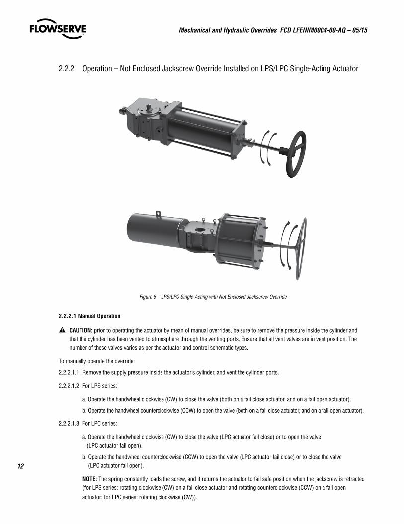
2.2.2 Operation – Not Enclosed Jackscrew Override Installed on LPS/LPC Single-Acting Actuator
Figure 6 – LPS/LPC Single-Acting with Not Enclosed Jackscrew Override
2.2.2.1 Manual Operation
a CAUTION: prior to operating the actuator by mean of manual overrides, be sure to remove the pressure inside the cylinder and that the cylinder has been vented to atmosphere through the venting ports. Ensure that all vent valves are in vent position. The number of these valves varies as per the actuator and control schematic types.
To manually operate the override:
2.2.2.1.1 Remove the supply pressure inside the actuator’s cylinder, and vent the cylinder ports.
2.2.2.1.2 For LPS series:
a. Operate the handwheel clockwise (CW) to close the valve (both on a fail close actuator, and on a fail open actuator).
b. Operate the handwheel counterclockwise (CCW) to open the valve (both on a fail close actuator, and on a fail open actuator).
2.2.2.1.3 For LPC series:
a. Operate the handwheel clockwise (CW) to close the valve (LPC actuator fail close) or to open the valve (LPC actuator fail open).
b. Operate the handwheel counterclockwise (CCW) to open the valve (LPC actuator fail close) or to close the valve (LPC actuator fail open).
NOTE: The spring constantly loads the screw, and it returns the actuator to fail safe position when the jackscrew is retracted (for LPS series: rotating clockwise (CW) on a fail close actuator and rotating counterclockwise (CCW) on a fail open
actuator; for LPC series: rotating clockwise (CW)).
13
Mechanical and Hydraulic Overrides FCD LFENIM0004-00-AQ – 05/15
flowserve.com
2.2.2.2 Restoring Automatic Operation
To restore automatic operation:
2.2.2.2.1 Operate handwheel in order to retract the jackscrews completely and lock the position with the safety lock1.
2.2.2.2.2 Restore the supply pressure inside the actuator’s cylinder.
2.2.2.2.3 Operate actuator normally with supply pressure.
2.2.2.2.4 Check that the actuator is able to reach the fully closed position in case of fail close actuator or the fully open position in case of fail open actuator. It is possible to check the fully stroked position by mean of visual position indicator or limit switches if fitted. In case the actuator is not able to fully stroke, verify that the jackscrew has been totally retracted, rotating it as described in first step.
1 The safety lock is only available upon request. Please contact your local Flowserve Limitorque Representative for more information.
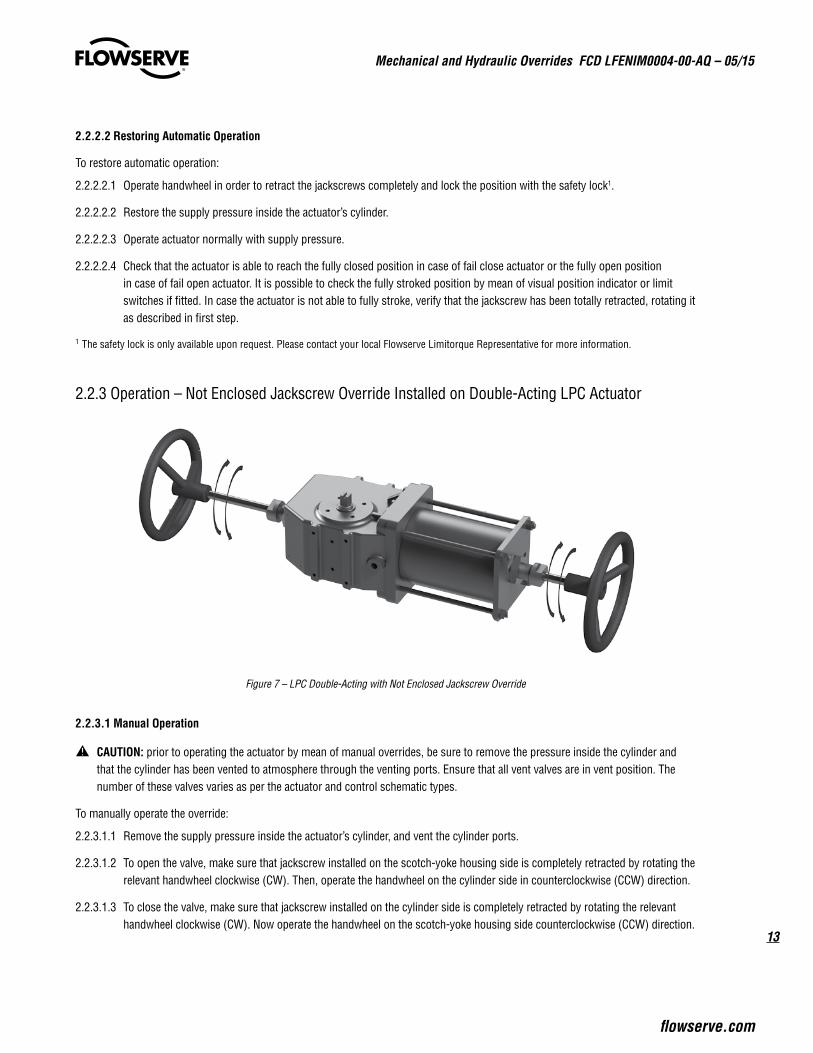
2.2.3 Operation – Not Enclosed Jackscrew Override Installed on Double-Acting LPC Actuator
Figure 7 – LPC Double-Acting with Not Enclosed Jackscrew Override
2.2.3.1 Manual Operation
a CAUTION: prior to operating the actuator by mean of manual overrides, be sure to remove the pressure inside the cylinder and that the cylinder has been vented to atmosphere through the venting ports. Ensure that all vent valves are in vent position. The number of these valves varies as per the actuator and control schematic types.
To manually operate the override:
2.2.3.1.1 Remove the supply pressure inside the actuator’s cylinder, and vent the cylinder ports.
2.2.3.1.2 To open the valve, make sure that jackscrew installed on the scotch-yoke housing side is completely retracted by rotating the relevant handwheel clockwise (CW). Then, operate the handwheel on the cylinder side in counterclockwise (CCW) direction.
2.2.3.1.3 To close the valve, make sure that jackscrew installed on the cylinder side is completely retracted by rotating the relevant handwheel clockwise (CW). Now operate the handwheel on the scotch-yoke housing side counterclockwise (CCW) direction.
Mechanical and Hydraulic Overrides FCD LFENIM0004-00-AQ – 05/15
14
2.2.3.2 Restoring Automatic Operation
To restore automatic operation:
2.2.3.2.1 Operate both handwheels clockwise (CW) in order to retract both jackscrews completely, and lock the position with the safety lock1.
2.2.3.2.2 Restore the supply pressure inside the actuator’s cylinder.
2.2.3.2.3 Operate actuator normally with supply pressure.
2.2.3.2.4 Check that the actuator is able to reach the fully closed position in case of fail close actuator, or the fully open position in case of fail open actuator. It is possible to check the fully stroked position by seeing the position indicator or limit switches, if fitted. In case the actuator is not able to stroke fully, verify that the jackscrew has been totally retracted by rotating it as described in step 2.2.3.2.1.
1 The safety lock is only available upon request. Please contact your local Flowserve Limitorque Representative for more information.
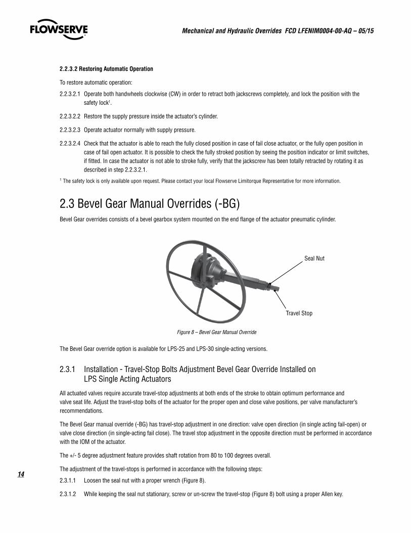
2.3 Bevel Gear Manual Overrides (-BG) Bevel Gear overrides consists of a bevel gearbox system mounted on the end flange of the actuator pneumatic cylinder.
Figure 8 – Bevel Gear Manual Override
The Bevel Gear override option is available for LPS-25 and LPS-30 single-acting versions.
2.3.1 Installation - Travel-Stop Bolts Adjustment Bevel Gear Override Installed on LPS Single Acting Actuators
All actuated valves require accurate travel-stop adjustments at both ends of the stroke to obtain optimum performance and valve seat life. Adjust the travel-stop bolts of the actuator for the proper open and close valve positions, per valve manufacturer’s recommendations.
The Bevel Gear manual override (-BG) has travel-stop adjustment in one direction: valve open direction (in single acting fail-open) or valve close direction (in single-acting fail close). The travel stop adjustment in the opposite direction must be performed in accordance with the IOM of the actuator.
The +/- 5 degree adjustment feature provides shaft rotation from 80 to 100 degrees overall.
The adjustment of the travel-stops is performed in accordance with the following steps:
2.3.1.1 Loosen the seal nut with a proper wrench (Figure 8).
2.3.1.2 While keeping the seal nut stationary, screw or un-screw the travel-stop (Figure 8) bolt using a proper Allen key.
Travel Stop
Seal Nut
15
Mechanical and Hydraulic Overrides FCD LFENIM0004-00-AQ – 05/15
flowserve.com
2.3.1.3 Tighten the seal nut.
2.3.1.4 Pneumatically stroke the actuator several times to assure proper operation. The stem adaptor should not bind during operation. If the actuator is equipped with limit switches, positioners or other accessories, adjust them at this time.
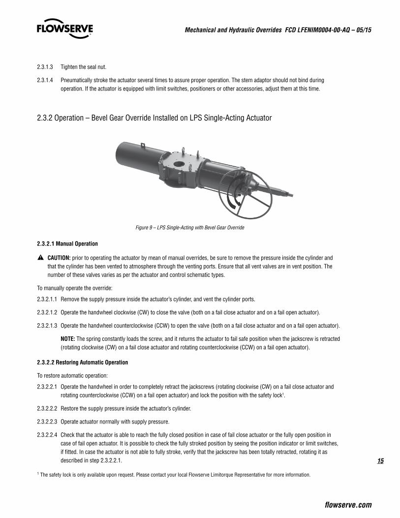
2.3.2 Operation – Bevel Gear Override Installed on LPS Single-Acting Actuator
Figure 9 – LPS Single-Acting with Bevel Gear Override
2.3.2.1 Manual Operation
a CAUTION: prior to operating the actuator by mean of manual overrides, be sure to remove the pressure inside the cylinder and that the cylinder has been vented to atmosphere through the venting ports. Ensure that all vent valves are in vent position. The number of these valves varies as per the actuator and control schematic types.
To manually operate the override:
2.3.2.1.1 Remove the supply pressure inside the actuator’s cylinder, and vent the cylinder ports.
2.3.2.1.2 Operate the handwheel clockwise (CW) to close the valve (both on a fail close actuator and on a fail open actuator).
2.3.2.1.3 Operate the handwheel counterclockwise (CCW) to open the valve (both on a fail close actuator and on a fail open actuator).
NOTE: The spring constantly loads the screw, and it returns the actuator to fail safe position when the jackscrew is retracted (rotating clockwise (CW) on a fail close actuator and rotating counterclockwise (CCW) on a fail open actuator).
2.3.2.2 Restoring Automatic Operation
To restore automatic operation:
2.3.2.2.1 Operate the handwheel in order to completely retract the jackscrews (rotating clockwise (CW) on a fail close actuator and rotating counterclockwise (CCW) on a fail open actuator) and lock the position with the safety lock1.
2.3.2.2.2 Restore the supply pressure inside the actuator’s cylinder.
2.3.2.2.3 Operate actuator normally with supply pressure.
2.3.2.2.4 Check that the actuator is able to reach the fully closed position in case of fail close actuator or the fully open position in case of fail open actuator. It is possible to check the fully stroked position by seeing the position indicator or limit switches, if fitted. In case the actuator is not able to fully stroke, verify that the jackscrew has been totally retracted, rotating it as described in step 2.3.2.2.1.
1 The safety lock is only available upon request. Please contact your local Flowserve Limitorque Representative for more information.
Mechanical and Hydraulic Overrides FCD LFENIM0004-00-AQ – 05/15
16
3 Hydraulic Manual Overrides
Hydraulic Manual Overrides of LFPS heavy duty actuators provides a low-effort and high-thrust compact sized override for manually operating the actuator. The LFPS Hydraulic Manual Overrides are designed in accordance with EN 12570 and the manual operation shall be completed with a force applied to the lever that does not exceed values stated in EN 12570.
a CAUTION: Prior to locally operating the valve and actuator by mean of manual overrides, remove the pressure inside the cylinder, and ensure that the cylinder has been vented through the venting ports. Ensure that all vent valves are in vent position. The number of these valves varies as per the actuator and control schematic types.
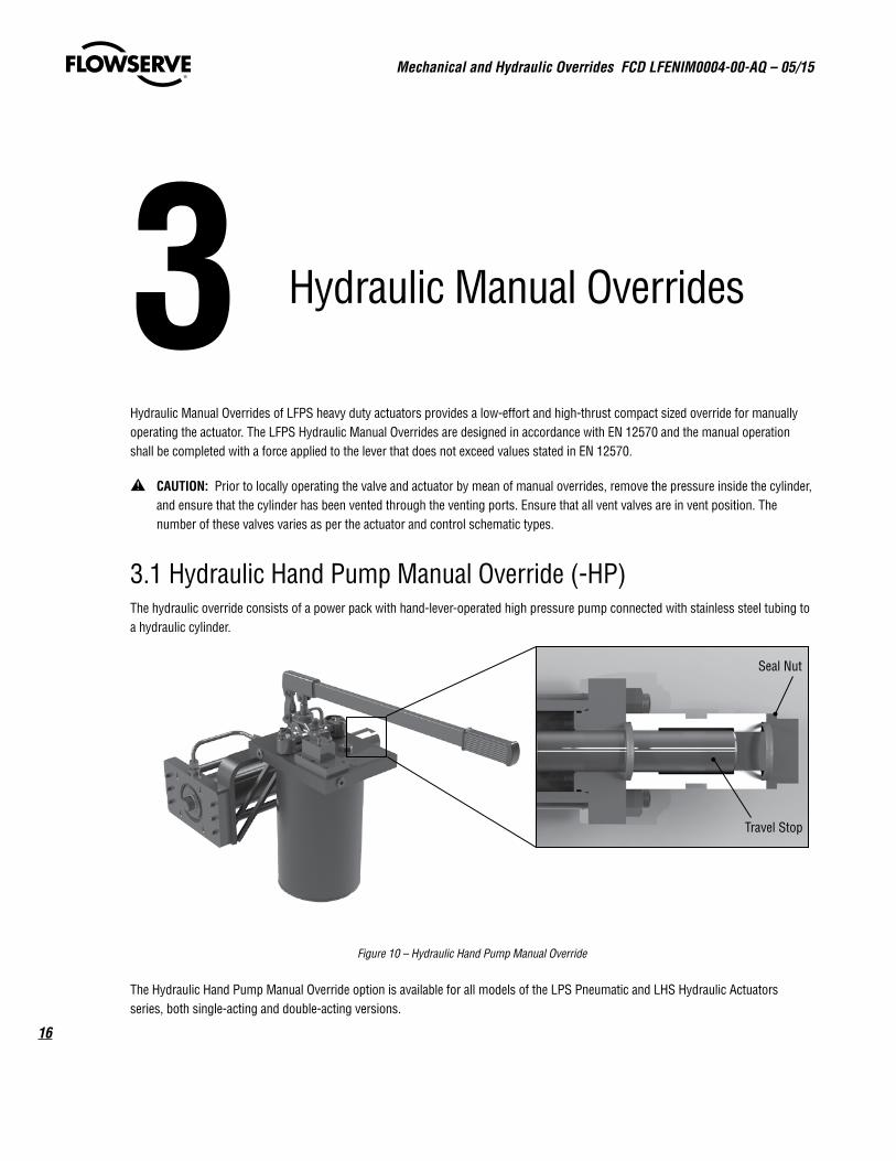
3.1 Hydraulic Hand Pump Manual Override (-HP) The hydraulic override consists of a power pack with hand-lever-operated high pressure pump connected with stainless steel tubing to a hydraulic cylinder.
Figure 10 – Hydraulic Hand Pump Manual Override
The Hydraulic Hand Pump Manual Override option is available for all models of the LPS Pneumatic and LHS Hydraulic Actuators series, both single-acting and double-acting versions.
Travel Stop
Seal Nut
17
Mechanical and Hydraulic Overrides FCD LFENIM0004-00-AQ – 05/15
flowserve.com
3.1.1 Installation - Travel-Stop Bolts Adjustment Hydraulic Hand Pump Override
All actuated valves require accurate travel-stop adjustments at both ends of the stroke to obtain optimum performance and valve seat life. Adjust the travel-stop bolts of the actuator for the proper open and close valve positions, per valve manufacturer’s recommendations.
The Hydraulic Hand Pump manual override (-HP) has travel-stop adjustment in one direction: valve open direction (in LPS/LHS single-acting fail open and in LPS double acting) or valve close direction (in LPS/LHS single-acting fail close and LHS double acting). The travel stop adjustment in the opposite direction must be performed in according with the IOM of the actuator.
The +/- 5 degree adjustment feature provides shaft rotation from 80 to 100 degrees overall.
The adjustment of the travel-stops is performed in accordance with the following steps:
3.1.1.1 Loosen the seal nut with a proper wrench (Figure 10).
3.1.1.2 While keeping the seal nut stationary, screw or un-screw the travel-stop (Figure 10) bolt using a proper Allen key.
3.1.1.3 Tighten the seal nut.
3.1.1.4 Stroke the actuator several times to assure proper operation. The stem adaptor should not bind during operation. If the actuator is equipped with limit switches, positioners or other accessories, adjust them at this time.
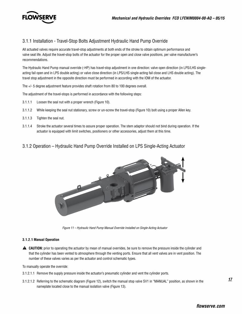
3.1.2 Operation – Hydraulic Hand Pump Override Installed on LPS Single-Acting Actuator
Figure 11 – Hydraulic Hand Pump Manual Override Installed on Single-Acting Actuator
3.1.2.1 Manual Operation
a CAUTION: prior to operating the actuator by mean of manual overrides, be sure to remove the pressure inside the cylinder and that the cylinder has been vented to atmosphere through the venting ports. Ensure that all vent valves are in vent position. The number of these valves varies as per the actuator and control schematic types.
To manually operate the override:
3.1.2.1.1 Remove the supply pressure inside the actuator’s pneumatic cylinder and vent the cylinder ports.
3.1.2.1.2 Referring to the schematic diagram (Figure 12), switch the manual stop valve SV1 in “MANUAL” position, as shown in the nameplate located close to the manual isolation valve (Figure 13).
Mechanical and Hydraulic Overrides FCD LFENIM0004-00-AQ – 05/15
18
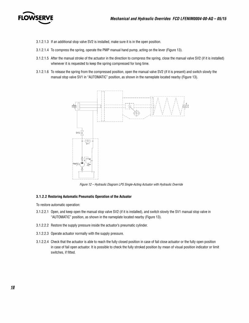
3.1.2.1.3 If an additional stop valve SV2 is installed, make sure it is in the open position.
3.1.2.1.4 To compress the spring, operate the PMP manual hand pump, acting on the lever (Figure 13).
3.1.2.1.5 After the manual stroke of the actuator in the direction to compress the spring, close the manual valve SV2 (if it is installed) whenever it is requested to keep the spring compressed for long time.
3.1.2.1.6 To release the spring from the compressed position, open the manual valve SV2 (if it is present) and switch slowly the manual stop valve SV1 in “AUTOMATIC” position, as shown in the nameplate located nearby (Figure 13).
Figure 12 – Hydraulic Diagram LPS Single-Acting Actuator with Hydraulic Override
3.1.2.2 Restoring Automatic Pneumatic Operation of the Actuator
To restore automatic operation:
3.1.2.2.1 Open, and keep open the manual stop valve SV2 (if it is installed), and switch slowly the SV1 manual stop valve in “AUTOMATIC” position, as shown in the nameplate located nearby (Figure 13).
3.1.2.2.2 Restore the supply pressure inside the actuator’s pneumatic cylinder.
3.1.2.2.3 Operate actuator normally with the supply pressure.
3.1.2.2.4 Check that the actuator is able to reach the fully closed position in case of fail close actuator or the fully open position in case of fail open actuator. It is possible to check the fully stroked position by mean of visual position indicator or limit switches, if fitted.
19
Mechanical and Hydraulic Overrides FCD LFENIM0004-00-AQ – 05/15
flowserve.com
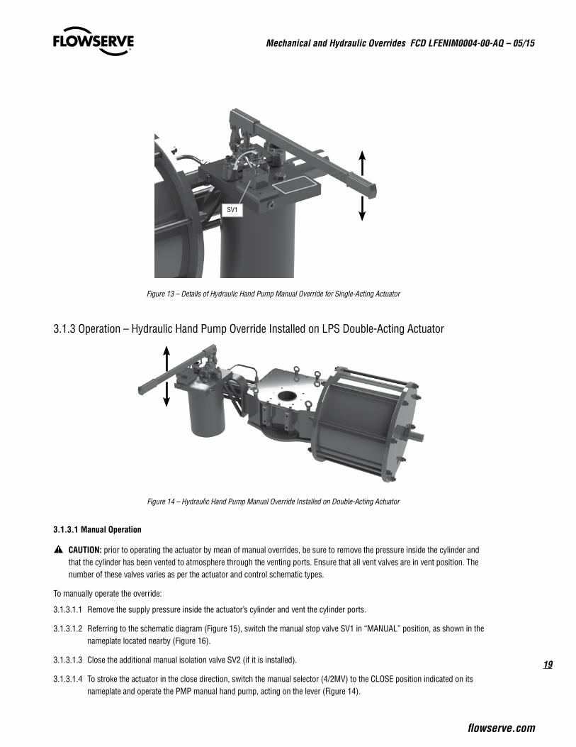
Figure 13 – Details of Hydraulic Hand Pump Manual Override for Single-Acting Actuator
3.1.3 Operation – Hydraulic Hand Pump Override Installed on LPS Double-Acting Actuator
Figure 14 – Hydraulic Hand Pump Manual Override Installed on Double-Acting Actuator
3.1.3.1 Manual Operation
a CAUTION: prior to operating the actuator by mean of manual overrides, be sure to remove the pressure inside the cylinder and that the cylinder has been vented to atmosphere through the venting ports. Ensure that all vent valves are in vent position. The number of these valves varies as per the actuator and control schematic types.
To manually operate the override:
3.1.3.1.1 Remove the supply pressure inside the actuator’s cylinder and vent the cylinder ports.
3.1.3.1.2 Referring to the schematic diagram (Figure 15), switch the manual stop valve SV1 in “MANUAL” position, as shown in the nameplate located nearby (Figure 16).
3.1.3.1.3 Close the additional manual isolation valve SV2 (if it is installed).
3.1.3.1.4 To stroke the actuator in the close direction, switch the manual selector (4/2MV) to the CLOSE position indicated on its nameplate and operate the PMP manual hand pump, acting on the lever (Figure 14).
SV1
Mechanical and Hydraulic Overrides FCD LFENIM0004-00-AQ – 05/15
20
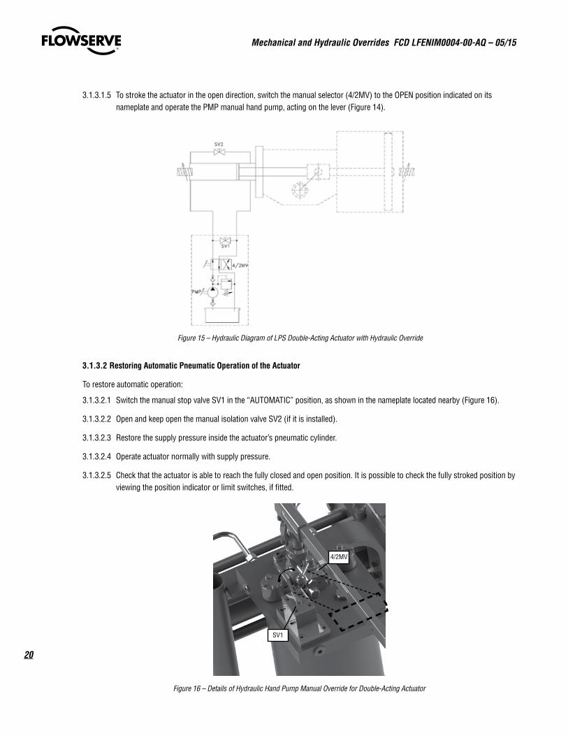
3.1.3.1.5 To stroke the actuator in the open direction, switch the manual selector (4/2MV) to the OPEN position indicated on its nameplate and operate the PMP manual hand pump, acting on the lever (Figure 14).
Figure 15 – Hydraulic Diagram of LPS Double-Acting Actuator with Hydraulic Override
3.1.3.2 Restoring Automatic Pneumatic Operation of the Actuator
To restore automatic operation:
3.1.3.2.1 Switch the manual stop valve SV1 in the “AUTOMATIC” position, as shown in the nameplate located nearby (Figure 16).
3.1.3.2.2 Open and keep open the manual isolation valve SV2 (if it is installed).
3.1.3.2.3 Restore the supply pressure inside the actuator’s pneumatic cylinder.
3.1.3.2.4 Operate actuator normally with supply pressure.
3.1.3.2.5 Check that the actuator is able to reach the fully closed and open position. It is possible to check the fully stroked position by viewing the position indicator or limit switches, if fitted.
Figure 16 – Details of Hydraulic Hand Pump Manual Override for Double-Acting Actuator
SV1
4/2MV
21
Mechanical and Hydraulic Overrides FCD LFENIM0004-00-AQ – 05/15
flowserve.com
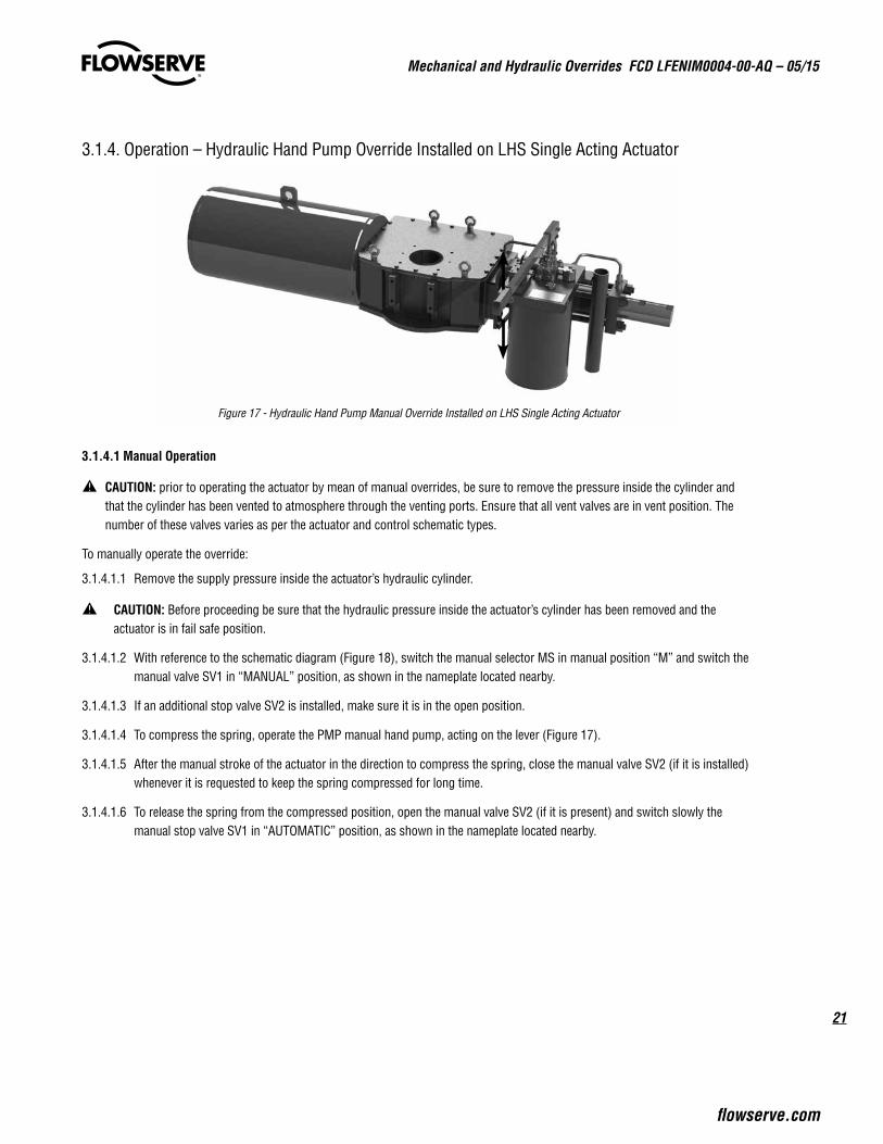
3.1.4. Operation – Hydraulic Hand Pump Override Installed on LHS Single Acting Actuator
Figure 17 - Hydraulic Hand Pump Manual Override Installed on LHS Single Acting Actuator
3.1.4.1 Manual Operation
a CAUTION: prior to operating the actuator by mean of manual overrides, be sure to remove the pressure inside the cylinder and that the cylinder has been vented to atmosphere through the venting ports. Ensure that all vent valves are in vent position. The number of these valves varies as per the actuator and control schematic types.
To manually operate the override:
3.1.4.1.1 Remove the supply pressure inside the actuator’s hydraulic cylinder.
a CAUTION: Before proceeding be sure that the hydraulic pressure inside the actuator’s cylinder has been removed and the actuator is in fail safe position.
3.1.4.1.2 With reference to the schematic diagram (Figure 18), switch the manual selector MS in manual position “M” and switch the manual valve SV1 in “MANUAL” position, as shown in the nameplate located nearby.
3.1.4.1.3 If an additional stop valve SV2 is installed, make sure it is in the open position.
3.1.4.1.4 To compress the spring, operate the PMP manual hand pump, acting on the lever (Figure 17).
3.1.4.1.5 After the manual stroke of the actuator in the direction to compress the spring, close the manual valve SV2 (if it is installed) whenever it is requested to keep the spring compressed for long time.
3.1.4.1.6 To release the spring from the compressed position, open the manual valve SV2 (if it is present) and switch slowly the manual stop valve SV1 in “AUTOMATIC” position, as shown in the nameplate located nearby.
Mechanical and Hydraulic Overrides FCD LFENIM0004-00-AQ – 05/15
22
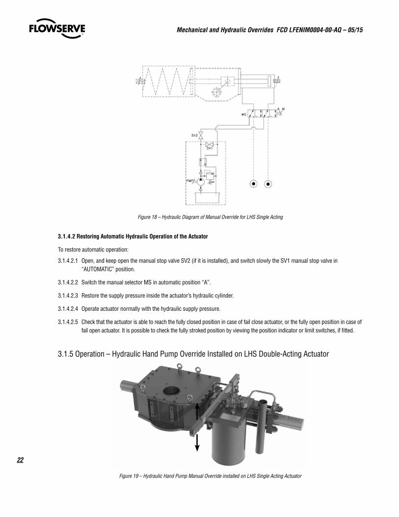
Figure 18 – Hydraulic Diagram of Manual Override for LHS Single Acting
3.1.4.2 Restoring Automatic Hydraulic Operation of the Actuator
To restore automatic operation:
3.1.4.2.1 Open, and keep open the manual stop valve SV2 (if it is installed), and switch slowly the SV1 manual stop valve in “AUTOMATIC” position.
3.1.4.2.2 Switch the manual selector MS in automatic position “A”.
3.1.4.2.3 Restore the supply pressure inside the actuator’s hydraulic cylinder.
3.1.4.2.4 Operate actuator normally with the hydraulic supply pressure.
3.1.4.2.5 Check that the actuator is able to reach the fully closed position in case of fail close actuator, or the fully open position in case of fail open actuator. It is possible to check the fully stroked position by viewing the position indicator or limit switches, if fitted.
3.1.5 Operation – Hydraulic Hand Pump Override Installed on LHS Double-Acting Actuator
Figure 19 – Hydraulic Hand Pump Manual Override installed on LHS Single Acting Actuator
23
Mechanical and Hydraulic Overrides FCD LFENIM0004-00-AQ – 05/15
flowserve.com
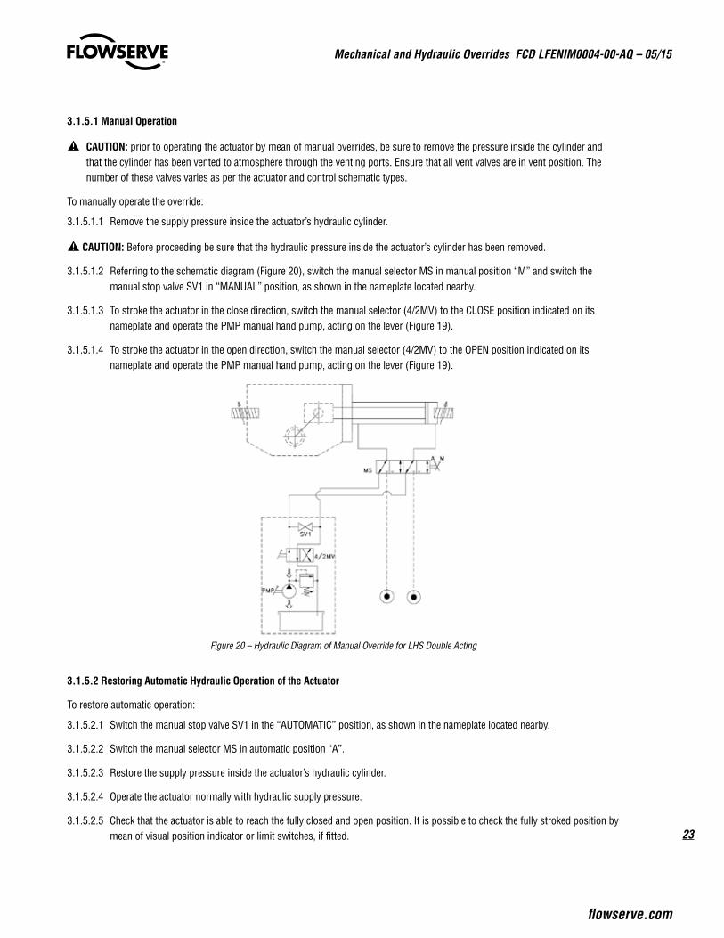
3.1.5.1 Manual Operation
a CAUTION: prior to operating the actuator by mean of manual overrides, be sure to remove the pressure inside the cylinder and that the cylinder has been vented to atmosphere through the venting ports. Ensure that all vent valves are in vent position. The number of these valves varies as per the actuator and control schematic types.
To manually operate the override:
3.1.5.1.1 Remove the supply pressure inside the actuator’s hydraulic cylinder.
a CAUTION: Before proceeding be sure that the hydraulic pressure inside the actuator’s cylinder has been removed.
3.1.5.1.2 Referring to the schematic diagram (Figure 20), switch the manual selector MS in manual position “M” and switch the manual stop valve SV1 in “MANUAL” position, as shown in the nameplate located nearby.
3.1.5.1.3 To stroke the actuator in the close direction, switch the manual selector (4/2MV) to the CLOSE position indicated on its nameplate and operate the PMP manual hand pump, acting on the lever (Figure 19).
3.1.5.1.4 To stroke the actuator in the open direction, switch the manual selector (4/2MV) to the OPEN position indicated on its nameplate and operate the PMP manual hand pump, acting on the lever (Figure 19).
Figure 20 – Hydraulic Diagram of Manual Override for LHS Double Acting
3.1.5.2 Restoring Automatic Hydraulic Operation of the Actuator
To restore automatic operation:
3.1.5.2.1 Switch the manual stop valve SV1 in the “AUTOMATIC” position, as shown in the nameplate located nearby.
3.1.5.2.2 Switch the manual selector MS in automatic position “A”.
3.1.5.2.3 Restore the supply pressure inside the actuator’s hydraulic cylinder.
3.1.5.2.4 Operate the actuator normally with hydraulic supply pressure.
3.1.5.2.5 Check that the actuator is able to reach the fully closed and open position. It is possible to check the fully stroked position by mean of visual position indicator or limit switches, if fitted.
Mechanical and Hydraulic Overrides FCD LFENIM0004-00-AQ – 05/15
24
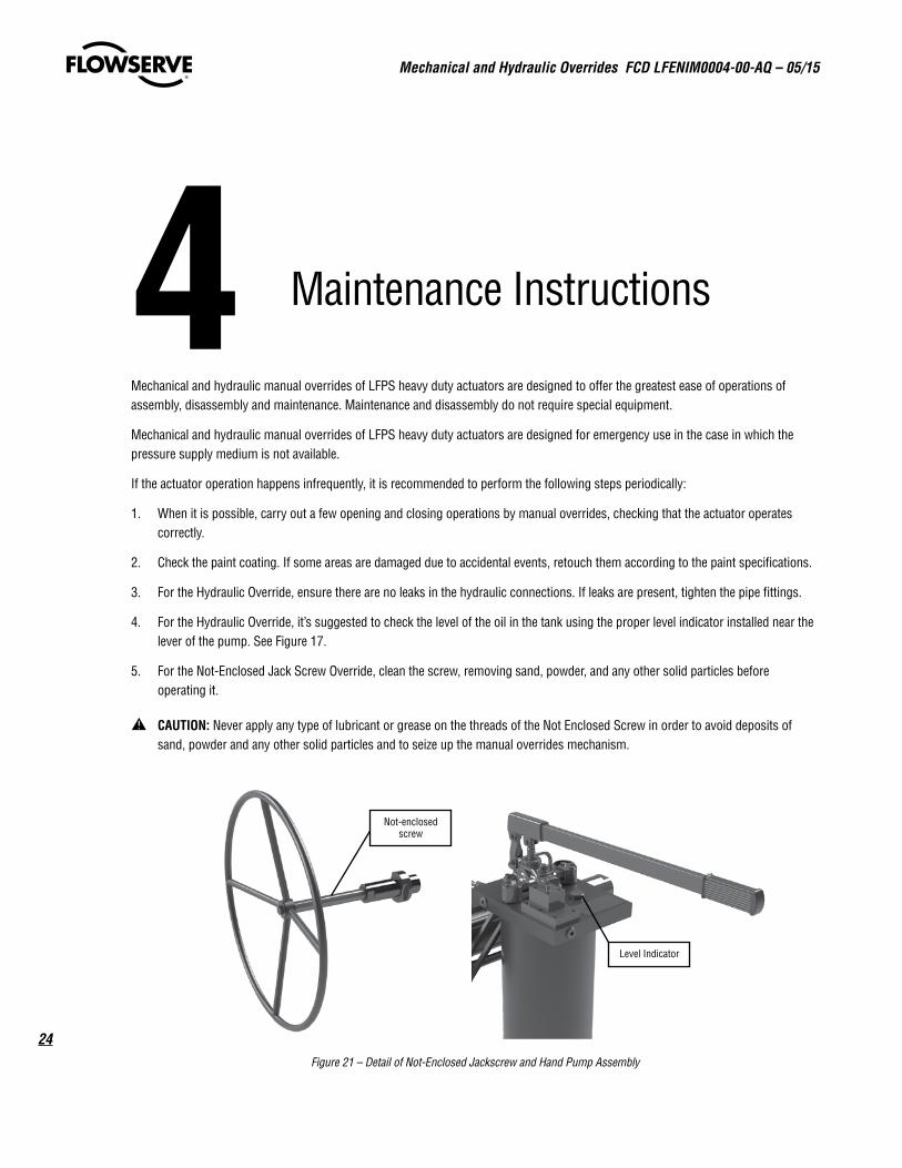
4 Maintenance Instructions
Mechanical and hydraulic manual overrides of LFPS heavy duty actuators are designed to offer the greatest ease of operations of assembly, disassembly and maintenance. Maintenance and disassembly do not require special equipment.
Mechanical and hydraulic manual overrides of LFPS heavy duty actuators are designed for emergency use in the case in which the pressure supply medium is not available.
If the actuator operation happens infrequently, it is recommended to perform the following steps periodically:
1. When it is possible, carry out a few opening and closing operations by manual overrides, checking that the actuator operates correctly.
2. Check the paint coating. If some areas are damaged due to accidental events, retouch them according to the paint specifications.
3. For the Hydraulic Override, ensure there are no leaks in the hydraulic connections. If leaks are present, tighten the pipe fittings.
4. For the Hydraulic Override, it’s suggested to check the level of the oil in the tank using the proper level indicator installed near the lever of the pump. See Figure 17.
5. For the Not-Enclosed Jack Screw Override, clean the screw, removing sand, powder, and any other solid particles before operating it.
a CAUTION: Never apply any type of lubricant or grease on the threads of the Not Enclosed Screw in order to avoid deposits of sand, powder and any other solid particles and to seize up the manual overrides mechanism.
Figure 21 – Detail of Not-Enclosed Jackscrew and Hand Pump Assembly
Not-enclosedscrew
Level Indicator
25
Mechanical and Hydraulic Overrides FCD LFENIM0004-00-AQ – 05/15
flowserve.com
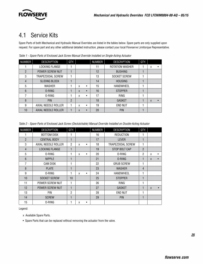
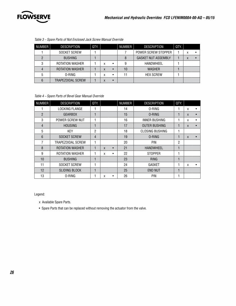
4.1 Service KitsSpare Parts of both Mechanical and Hydraulic Manual Overrides are listed in the tables below. Spare parts are only supplied upon request. For spare part and any other additional detailed instruction, please contact your local Flowserve Limitorque Representative.
Table 1 – Spare Parts of Enclosed Jack Screw Manual Override Installed on Single-Acting Actuator
NUMBER DESCRIPTION QTY. NUMBER DESCRIPTION QTY.
1 LOCKING FLANGE 1 11 ROTATION WASHER 1 x •
2 POWER SCREW NUT 1 12 BUSHING 1
3 TRAPEZOIDAL SCREW 1 13 SOCKET SCREW 1
4 SLIDING BLOCK 1 14 HOUSING 1
5 WASHER 1 x • 15 HANDWHEEL 1
6 O-RING 1 x • 16 STOPPER 1
7 O-RING 1 x • 17 RING 1
8 PIN 2 18 GASKET 1 x •
9 AXIAL NEEDLE ROLLER 1 x • 19 END NUT 1
10 AXIAL NEEDLE ROLLER 1 x • 20 PIN 1
Table 2 – Spare Parts of Enclosed Jack Screw (Declutchable) Manual Override Installed on Double-Acting Actuator
NUMBER DESCRIPTION QTY. NUMBER DESCRIPTION QTY.
1 BOTTOM DISK 1 16 REDUCTION 1
2 CENTRAL BODY 1 17 LEVER 1
3 AXIAL NEEDLE ROLLER 2 x • 18 TRAPEZOIDAL SCREW 1
4 LOCKING FLANGE 1 19 STOP BOLT CAP 2
5 O-RING 1 x • 20 O-RING 2 x •
6 NIPPLE 1 21 O-RING 1 x •
7 CAM DISK 1 22 GRUB SCREW 1
8 PLATE 1 23 WASHER 4
9 O-RING 1 x • 24 HANDWHEEL 1
10 SOCKET SCREW 10 25 STOPPER 1
11 POWER SCREW NUT 1 26 RING 1
12 POWER SCREW NUT 1 27 GASKET 1 x •
13 PIN 2 28 END NUT 1
14 SCREW 1 29 PIN 1
15 O-RING 1 x •
Legend:
x Available Spare Parts.
• Spare Parts that can be replaced without removing the actuator from the valve.
Mechanical and Hydraulic Overrides FCD LFENIM0004-00-AQ – 05/15
26
Table 3 – Spare Parts of Not Enclosed Jack Screw Manual Override
NUMBER DESCRIPTION QTY. NUMBER DESCRIPTION QTY.
1 SOCKET SCREW 1 7 POWER SCREW STOPPER 1 x •
2 BUSHING 1 8 GASKET NUT ASSEMBLY 1 x •
3 ROTATION WASHER 1 x • 9 HANDWHEEL 1
4 ROTATION WASHER 1 x • 10 WASHER 1
5 O-RING 1 x • 11 HEX SCREW 1
6 TRAPEZOIDAL SCREW 1 x •
Table 4 – Spare Parts of Bevel Gear Manual Override
NUMBER DESCRIPTION QTY. NUMBER DESCRIPTION QTY.
1 LOCKING FLANGE 1 14 O-RING 1 x •
2 GEARBOX 1 15 O-RING 1 x •
3 POWER SCREW NUT 1 16 INNER BUSHING 1 x •
4 HOUSING 1 17 OUTER BUSHING 1 x •
5 KEY 2 18 CLOSING BUSHING 1
6 SOCKET SCREW 4 19 O-RING 1 x •
7 TRAPEZOIDAL SCREW 1 20 PIN 2
8 ROTATION WASHER 1 x • 21 HANDWHEEL 1
9 ROTATION WASHER 1 x • 22 STOPPER 1
10 BUSHING 1 23 RING 1
11 SOCKET SCREW 1 24 GASKET 1 x •
12 SLIDING BLOCK 1 25 END NUT 1
13 O-RING 1 x • 26 PIN 1
Legend:
x Available Spare Parts.
• Spare Parts that can be replaced without removing the actuator from the valve.
27
Mechanical and Hydraulic Overrides FCD LFENIM0004-00-AQ – 05/15
flowserve.com
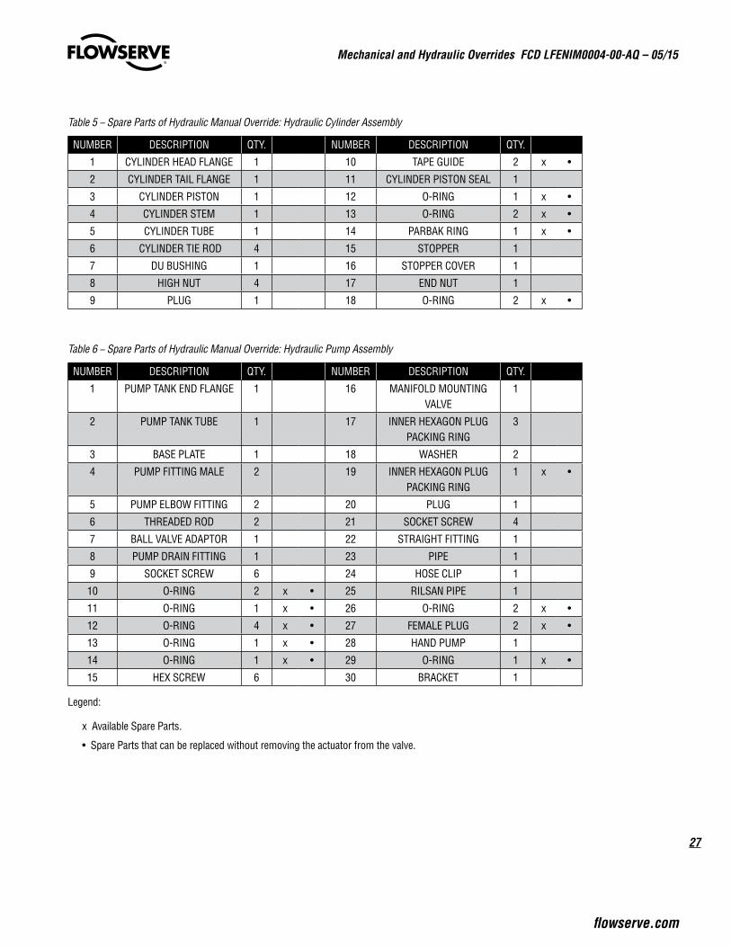
Table 5 – Spare Parts of Hydraulic Manual Override: Hydraulic Cylinder Assembly
NUMBER DESCRIPTION QTY. NUMBER DESCRIPTION QTY.
1 CYLINDER HEAD FLANGE 1 10 TAPE GUIDE 2 x •
2 CYLINDER TAIL FLANGE 1 11 CYLINDER PISTON SEAL 1
3 CYLINDER PISTON 1 12 O-RING 1 x •
4 CYLINDER STEM 1 13 O-RING 2 x •
5 CYLINDER TUBE 1 14 PARBAK RING 1 x •
6 CYLINDER TIE ROD 4 15 STOPPER 1
7 DU BUSHING 1 16 STOPPER COVER 1
8 HIGH NUT 4 17 END NUT 1
9 PLUG 1 18 O-RING 2 x •
Table 6 – Spare Parts of Hydraulic Manual Override: Hydraulic Pump Assembly
NUMBER DESCRIPTION QTY. NUMBER DESCRIPTION QTY.
1 PUMP TANK END FLANGE 1 16 MANIFOLD MOUNTING VALVE
1
2 PUMP TANK TUBE 1 17 INNER HEXAGON PLUG PACKING RING
3
3 BASE PLATE 1 18 WASHER 2
4 PUMP FITTING MALE 2 19 INNER HEXAGON PLUG PACKING RING
1 x •
5 PUMP ELBOW FITTING 2 20 PLUG 1
6 THREADED ROD 2 21 SOCKET SCREW 4
7 BALL VALVE ADAPTOR 1 22 STRAIGHT FITTING 1
8 PUMP DRAIN FITTING 1 23 PIPE 1
9 SOCKET SCREW 6 24 HOSE CLIP 1
10 O-RING 2 x • 25 RILSAN PIPE 1
11 O-RING 1 x • 26 O-RING 2 x •
12 O-RING 4 x • 27 FEMALE PLUG 2 x •
13 O-RING 1 x • 28 HAND PUMP 1
14 O-RING 1 x • 29 O-RING 1 x •
15 HEX SCREW 6 30 BRACKET 1
Legend:
x Available Spare Parts.
• Spare Parts that can be replaced without removing the actuator from the valve.
flowserve.com
To find your local Flowserve representative or for more information about Flowserve Corporation, visit www.flowserve.com.
FCD LFENIM0004-00-AQ Printed in USA. May 2015
Flowserve Corporation has established industry leadership in the design and manufacture of its products. When properly selected, this Flowserve product is designed to perform its intended function safely during its useful life. However, the purchaser or user of Flowserve products should be aware that Flowserve products might be used in numerous applications under a wide variety of industrial service conditions. Although Flowserve can (and often does) provide general guidelines, it cannot provide specific data and warnings for all possible applications. The pur-chaser/user must therefore assume the ultimate responsibility for the proper sizing and selection, installation, operation, and maintenance of Flowserve products. The purchaser/user should read and understand the Installation Operation Maintenance (IOM) instructions included with the product, and train its employees and contractors in the safe use of Flowserve products in connection with the specific application.
While the information and specifications contained in this literature are believed to be accurate, they are supplied for informative purposes only and should not be considered certified or as a guarantee of satisfactory results by reliance thereon. Nothing contained herein is to be construed as a warranty or guarantee, express or implied, regarding any matter with respect to this product. Because Flowserve is continually improving and upgrading its product design, the specifications, dimensions and information contained herein are subject to change without notice. Should any question arise concerning these provisions, the purchaser/user should contact Flowserve Corporation at any one of its worldwide operations or offices.
© 2015 Flowserve Corporation, Irving, Texas, USA. Flowserve is a registered trademark of Flowserve Corporation.
Flowserve Limitorque Fluid Power SystemsProduct SalesVia Rio Vallone 1720883 Mezzago (MB), ItalyPhone: +39 039 62060 1Fax: +39 039 62060 213Email: [email protected]
Flowserve LimitorqueFluid Power SystemsManufacturing and Operations Via Rio Vallone 1720883 Mezzago (MB), ItalyPhone: +39 039 62060 1Fax: +39 039 62060 213Email: [email protected]
Flowserve LimitorqueFluid Power Systems Research and DevelopmentViale dell’Artigianato 2429122 Piacenza (PC), ItalyEmail: [email protected]