user instructions - flowserve · user instructions desuperheaters fcd vlenim0115-00 – 09/11...
TRANSCRIPT

Experience In Motion
USER INSTRUCTIONS
DesuperheatersFCD VLENIM0115-00 – 09/11
Installation Operation
Maintenance

2
3
Desuperheaters FCD VLENIM0115-00 – 09/11
flowserve.com
This bulletin contains descriptions of the MaxCool MCX, VaporCool, and VaporCool MicroNozzle desuperheaters along with their basic principles of operation and characteristics. Also included are instructions for installing, operating and maintaining these desuperheaters. The information contained herein is intended to be a general guide for steam desuperheating applications.
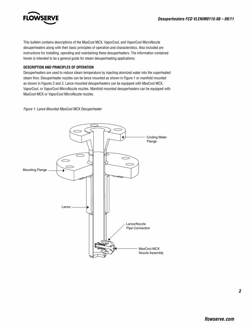
DESCRIPTION AND PRINCIPLES OF OPERATION Desuperheaters are used to reduce steam temperature by injecting atomized water into the superheated steam flow. Desuperheater nozzles can be lance mounted as shown in Figure 1 or manifold mounted as shown in Figures 2 and 3. Lance mounted desuperheaters can be equipped with MaxCool MCX, VaporCool, or VaporCool MicroNozzle nozzles. Manifold mounted desuperheaters can be equipped with MaxCool MCX or VaporCool MicroNozzle nozzles.
Figure 1: Lance Mounted MaxCool MCX Desuperheater
Cooling Water Flange
Lance/Nozzle Pipe Connection
MaxCool MCX Nozzle Assembly
Lance
Mounting Flange

Desuperheaters FCD VLENIM0115-00– 09/11
4
Figure 2: Manifold Mounted MaxCool MCX Desuperheater
Figure 3: Nozzle Housing Assembly
Manifold Tee
Manifold Pipe
Manifold Connector
Connecting Pipe
Steam Pipe
End Flange
Nozzle Housing Assembly(See Figure 3)
Nozzle Housing Cap Flange
Nozzle Seat Retainer
Cap Flange Bolting
GasketsWeld
Tack Weld
Nozzle Housing
MaxCool MCX Nozzle Assembly
(See Figure 4)
Steam Pipe Wall

5
Desuperheaters FCD VLENIM0115-00 – 09/11
flowserve.com
MaxCool MCX NozzleThe MaxCool MCX nozzle is a variable area hollow cone nozzle that produces a fine droplet spray mist. Figure 4 shows a cross-section of the nozzle assembly with the parts identified. The maximum range-ability for the MaxCool MCX nozzle is approximately 20:1.
The plug is assembled through the seat and is biased against the seat with a spring. The spring is held in place with a retainer that is screwed onto the plug. The retainer limits the stroke of the plug to ensure proper water atomization. A castle nut with an expansion pin or a bent washer locks the assembly together.
The geometry of the nozzle assembly is optimized to provide efficient cooling by minimizing water droplet size. When the Δp between the cooling water and the steam is sufficient to overcome the preload of the spring, the plug moves away from the seat and cooling water circulates through the nozzle open-ings. As the water moves down the conical shaped plug and exits past the sharp edges of the narrow plug opening, the cooling water is atomized into a fine spray mist.
Figure 4: MaxCool MCX Nozzle Assembly Cross-Section
Castle NutExpansion Pin
Spring
Mounting Thread
Seat
Retainer
Stroke Length
Nozzle Openings
Nozzle DiameterPlug
Desuperheaters FCD VLENIM0115-00– 09/11
6
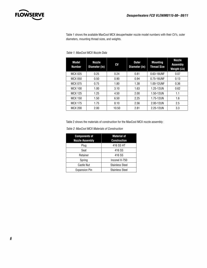
Table 1 shows the available MaxCool MCX desuperheater nozzle model numbers with their CV’s, outer diameters, mounting thread sizes, and weights.
Table 1: MaxCool MCX Nozzle Data
Model Number
Nozzle Diameter (in)
CVOuter
Diameter (in)Mounting
Thread Size
Nozzle Assembly
Weight (Lb)
MCX 025 0.25 0.24 0.81 0.63-18UNF 0.07
MCX 050 0.50 0.90 0.94 0.75-16UNF 0.13
MCX 075 0.75 1.80 1.38 1.00-12UNF 0.36
MCX 100 1.00 3.10 1.63 1.25-12UN 0.62
MCX 125 1.25 4.50 2.00 1.50-12UN 1.1
MCX 150 1.50 6.50 2.25 1.75-12UN 1.6
MCX 175 1.75 8.10 2.56 2.00-12UN 2.5
MCX 200 2.00 10.50 2.81 2.25-12UN 3.3
Table 2 shows the materials of construction for the MaxCool MCX nozzle assembly:
Table 2: MaxCool MCX Materials of Construction
Components of Nozzle Assembly
Material of Construction
Plug 416 SS HT
Seat 416 SS
Retainer 416 SS
Spring Inconel X-750
Castle Nut Stainless Steel
Expansion Pin Stainless Steel

7
Desuperheaters FCD VLENIM0115-00 – 09/11
flowserve.com
Each MaxCool MCX nozzle assembly is available in 1, 3, and 5 bar set pressures. Figure 5 shows the CV versus Δp for each set pressure value.
Figure 5: MaxCool MCX CV vs Δp
The minimum ΔP for the MaxCool MCX nozzle is 2 Bar for a nozzle with a 1 Bar cracking pressure spring, 4 Bar for a nozzle with a 3 Bar cracking pressure spring, and 6 Bar for a nozzle with a 5 Bar cracking pressure spring. The maximum ΔP is 30 Bar.
Generally, smaller nozzles and higher cracking pressures produce smaller water droplet sizes.

Desuperheaters FCD VLENIM0115-00– 09/11
8
VaporCool NozzleThe VaporCool nozzle is a fixed area full cone nozzle that produces a fine droplet spray mist. There are 7 small fixed area hollow cone nozzles mounted in the nozzle face. The interactions of the multiple hollow cone sprays produce a full cone spray pattern. These multi-orifice nozzles produce a finer spray than standard full cone nozzles of comparable size. Figures 6 and 7 show views of the VaporCool Nozzle. The VaporCool nozzle material of construction is 316 SS. The maximum rangeability of the VaporCool nozzle is 5:1.
Figure 6: VaporCool Nozzle
Figure 7: Cross-Section of VaporCool Nozzle

9
Desuperheaters FCD VLENIM0115-00 – 09/11
flowserve.com
Table 3 shows the available VaporCool nozzle model numbers with mounting thread sizes, CV’s, outer diameters, and minimum operating ΔP’s. The nozzle maximum optimum ΔP is 10 Bar. The maximum ΔP is 20 Bar.
Table 3: VaporCool Nozzle Data
Model Number with Female NPT Mounting Thread Size
CV OD (in) Min ΔP (Bar)
CAS 1153 1/2" 0.062 1.97 2.0
CAS 1274 1/2" 0.111 1.97 1.0
CAS 1343 3/4" 0.139 2.83 0.5
CAS 1551 3/4" 0.223 2.83 0.5
CAS 1870 3/4" 0.353 2.83 0.5
CAS 2116 3/4" 0.470 2.83 0.5
CAS 2145 3/4" 0.588 2.83 0.5
CAS 2184 3/4" 0.746 2.83 0.5
CAS 2220 3/4" 0.894 2.83 0.5
CAS 2342 3/4" 1.390 2.83 0.5
CAS 2434 3/4" 1.762 2.83 0.5
CAS 2551 3/4" 2.234 2.83 0.5
CAS 2728 3/4" 2.951 2.83 0.5
CAS 2385 1" 1.564 5.51 0.5
CAS 2489 1" 1.986 5.51 0.5
CAS 2685 1" 2.780 5.51 0.5
CAS 3130 2" 5.269 7.28 0.5
CAS 3184 2" 7.458 7.28 0.5
CAS 3245 2" 9.930 7.28 0.5
VaporCool MicroNozzleThe VaporCool MicroNozzle is a low flow fixed area hollow cone nozzle that produces very fine atomized sprays. These nozzles are made from 316 SS and have ¼" NPT male mounting threads. Figure 8 shows a view of this nozzle. Table 4 shows the nozzle model numbers, CV’s and minimum operating ΔP’s. The maximum operating ΔP is 40 Bar. The maximum rangeability of the VaporCool MicroNozzle is 5:1.
Figure 8: VaporCool MicroNozzle

Desuperheaters FCD VLENIM0115-00– 09/11
10
Table 4: VaporCool MicroNozzle Data
Nozzle Model No. CV Min ΔP (Bar)
1/4M-316SS .60 0.0016 5.0
1/4M-316SS 1 0.0027 3.0
1/4M-316SS 1.5 0.004 2.5
1/4M-316SS 2 0.005 2.0
1/4M-316SS 3 0.008 1.5
1/4M-316SS 4 0.011 1.5
1/4M-316SS 6 0.016 1.5
1/4M-316SS 8 0.021 1.5
1/4M-316SS 10 0.026 1.0
1/4M-316SS 12 0.032 1.0
1/4M-316SS 14 0.037 1.0
1/4M-316SS 16 0.042 1.0
1/4M-316SS 18 0.047 1.0
1/4M-316SS 20 0.053 1.0
1/4M-316SS 22 0.058 1.0
1/4M-316SS 26 0.068 1.0
Multiple nozzles can be mounted on one lance to increase rangeability. See Figure 9.
Figure 9: View of MaxCool MCX nozzle and VaporCool MicroNozzle combined on one lance for increased rangeability
11
Desuperheaters FCD VLENIM0115-00 – 09/11
flowserve.com
DESUPERHEATER INSTALLATION (LANCE MOUNTED)1. The desuperheater mounting flange and the cooling water flange are manufactured with the bolting
holes straddling the steam pipe centerline and the nozzle head. Exceptions to this rule must be clearly stated on the Technical Requirement Sheet when the desuperheater is ordered.
c WARNING: When unpacking the desuperheater, care should be given to prevent foreign particles from entering the cooling water flange opening. These particles can block the small passages in the nozzles and impede water atomization.
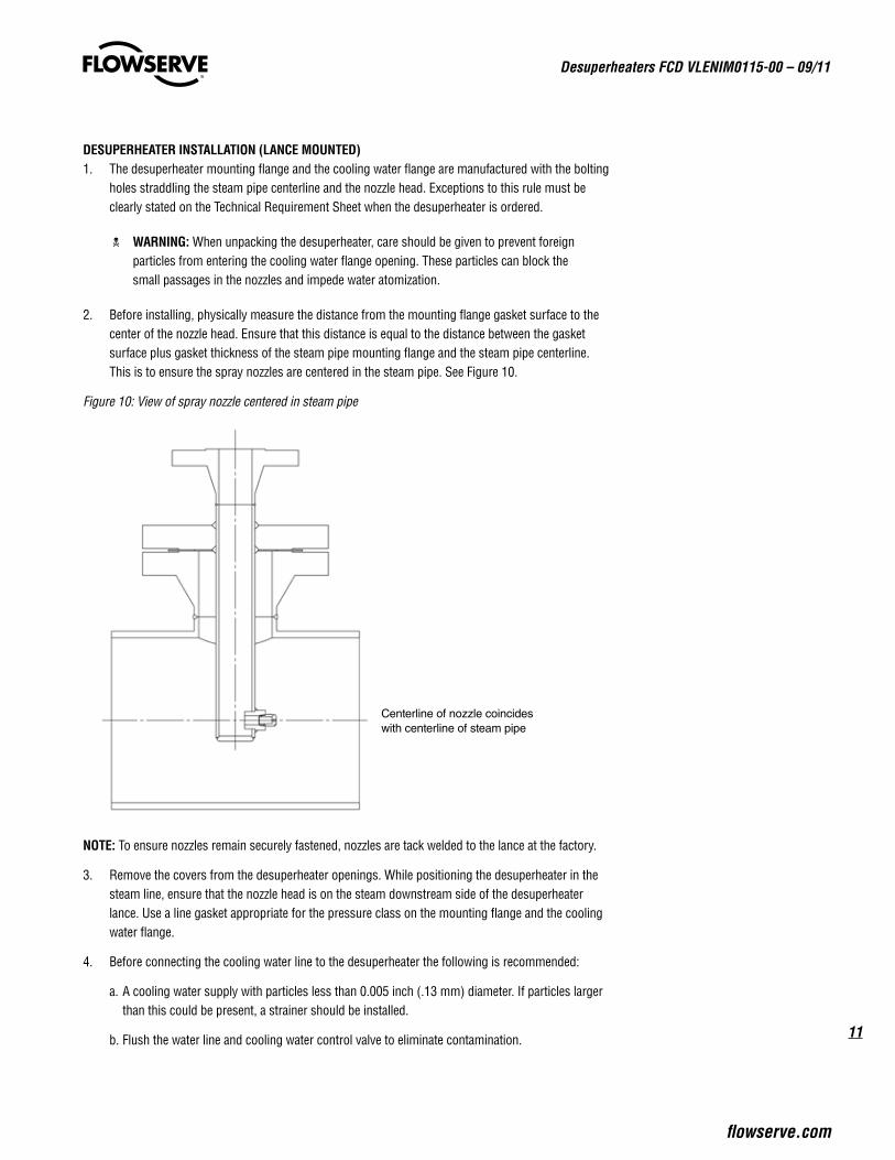
2. Before installing, physically measure the distance from the mounting flange gasket surface to the center of the nozzle head. Ensure that this distance is equal to the distance between the gasket surface plus gasket thickness of the steam pipe mounting flange and the steam pipe centerline. This is to ensure the spray nozzles are centered in the steam pipe. See Figure 10.
Figure 10: View of spray nozzle centered in steam pipe
NOTE: To ensure nozzles remain securely fastened, nozzles are tack welded to the lance at the factory.
3. Remove the covers from the desuperheater openings. While positioning the desuperheater in the steam line, ensure that the nozzle head is on the steam downstream side of the desuperheater lance. Use a line gasket appropriate for the pressure class on the mounting flange and the cooling water flange.
4. Before connecting the cooling water line to the desuperheater the following is recommended:
a. A cooling water supply with particles less than 0.005 inch (.13 mm) diameter. If particles larger than this could be present, a strainer should be installed.
b. Flush the water line and cooling water control valve to eliminate contamination.
Centerline of nozzle coincides with centerline of steam pipe

Desuperheaters FCD VLENIM0115-00– 09/11
12
a CAUTION: Failure to prevent particulate or debris from entering the desuperheater can cause malfunction of the nozzles, poor temperature control, and dangerous equipment failures.
5. Install and tighten line bolting on the mounting flange and cooling water flange to typical line bolting torque values.
OPERATIONDesuperheaters should maintain the following conditions to operate optimally.
1. The cooling water control valve should be capable of tight ASME Class V or VI shutoff.
c WARNING: Leaky cooling water valves could cause dripping water to impinge on equip-ment causing thermal shock resulting in equipment damage.
a CAUTION: If the temperature difference between the cooling water and the steam is greater than about 800°F (427°C) thermal fatigue may need to be considered more closely.
2. The minimum steam velocity should generally be 33 ft/s (10 m/s), but should be greater than the limits shown in Figure 11. The maximum steam velocity generally is 250 ft/s (76 m/s) but should not exceed 350 ft/s (107 m/s).
Figure 11: Minimum Steam Velocity for Atomization
c WARNING: Steam velocities below the minimum values listed may not provide adequate turbulence for mixing. This could result in cooling water falling out of the steam and impinging on the pipe resulting in equipment damage.
c WARNING: Steam velocities higher than the maximum values listed may result in stratified steam in the piping and may require excessive straight pipe lengths for adequate cooling water evaporation which could result in equipment damage.
3. For the MaxCool MCX nozzle the minimum pressure drop between the steam and the cooling water should be 2.0 bar (29 psig) for a 1 bar (14.5 psig) cracking pressure nozzle, 4 bar (58 psig) for a 3 bar (43.5 psig) cracking pressure nozzle, and 6 bar (87 psig) for a 5 bar (72.5 psig) cracking pres-sure nozzle. The minimum pressure drops between the steam and the cooling water for VaporCool and VaporCool MicroNozzles are shown in Tables 3 and 4.

13
Desuperheaters FCD VLENIM0115-00 – 09/11
flowserve.com
c WARNING: Operating nozzles below the minimum ΔP creates undeveloped water spray patterns with large droplet sizes which could impinge on equipment causing thermal shock resulting in equipment damage.
4. The maximum pressure drop between the steam and the water should be approximately 30.0 bar (435 psi) for the MaxCool MCX nozzle. The optimum maximum pressure drop for the VaporCool nozzle is 10 Bar (145 psi), but pressure drops up to 20 Bar (290 psi) are acceptable. The maximum pressure drop for the VaporCool MicroNozzle is 40 Bar (580 psi).
5. Higher cooling water temperatures will provide for more efficient atomization and evaporation.
6. Condensate is most likely to build up in lines during system startup and shutdown. The effects of corrosion and thermal shock on steam pipes can be reduced by minimizing process deviations.
7. The cooling water control valve should have a “fail close" actuator.
8. To enhance proper cooling water evaporation there should be a minimum of 10 feet (3 meters) of straight downstream pipe from the desuperheater location with a slight downward gradient. Factors such as velocity, how close the steam temperature is to saturation temperature, percent of cooling water being injected, pipe diameter, etc. can require longer straight pipe lengths. The minimum required straight pipe length for the actual application is provided on the desuperheater sizing sheet.
c WARNING: Inadequate straight pipe length does not allow sufficient time for the cooling water to evaporate allowing cooling water impingement on the piping system, especially the downstream elbow, causing thermal fatigue and premature failure.
9. To allow for accurate temperature feedback, the temperature sensor(s) should be located a minimum distance of 12 ft downstream of the desuperheater. Factors such as velocity, how close the steam temperature is to saturation temperature, percent of cooling water being injected, pipe diameter, etc. can require longer distances to the temperature sensor. The minimum required distance to the temperature sensor for the actual application is provided on the desuperheater sizing sheet. Multiple shielded temperature sensors will provide more accurate average feedback.
c WARNING: Inadequate distance from the desuperheater to the temperature sensor can cause inaccurate temperature measurement resulting in poor process control.
10. A pipe drain and/or steam trap should be placed at least 6 pipe diameters downstream of the desuperheater.
11. When cooling water flows over 50 gpm are required, for optimum performance, consider using multiple nozzles and/or multiple injection sites. This allows smaller water droplet sizes, better cooling water evaporation, and lower risk of cooling water impingement on the piping system.
MAINTENANCE (LANCE MOUNTED)Maintenance of lance mounted desuperheater nozzles may be required if:
• A degradation in cooling efficiency is noted while maintaining constant steam process conditions. This may be an indication that the nozzle is partially plugged.
• The steam process conditions change. If the steam load increases, the nozzle may need to be upsized to keep the downstream steam at the required temperature.

Desuperheaters FCD VLENIM0115-00– 09/11
14
AB
MaxCool MCXFollow steps 1-10 and refer to Figures 1 and 4 to clean or replace the MaxCool MCX desuperheater nozzle.
1. Depressurize the steam and cooling water lines. Drain the cooling water line and disconnect the cooling water line from the desuperheater. Remove the desuperheater from the steam line.
2. Carefully grind off the tack welds between the nozzle assembly and the lance pipe connection.
3. Unscrew the nozzle assembly off of the lance pipe connection.
4. Remove expansion pin from plug. Unscrew castle nut. The MCX 025 has a regular nut and bent washer in place of a castle nut and expansion pin. Unscrew retainer and remove spring. Remove plug from seat.
5. If cleaning is required: With compressed air blow out the passageways of the nozzle openings and clean the seat and plug surfaces. Inspect parts for wear, contamination, and blockage. Replace if worn or broken.
6. To reassemble nozzle assembly install plug through seat. Install spring and screw on retainer. Set maximum stroke of plug by screwing retainer until dimension B is met as shown in Figure 12 and Table 5. After maximum stroke is set with retainer, screw on castle nut to lock retainer position and reinsert expansion pin through plug. Be careful to retain stroke dimension during castle nut and expansion pin assembly. On MCX 025 bend washer to lock nut.
7. Inspect lance for wear, leaks, or cracks. Replace or repair if necessary.
8. Install the nozzle assembly onto the lance pipe connection with torque values shown in Table 5.
9. Apply tack weld in two places to face of lance nozzle pipe connection by flats of nozzle assembly seat. The tack weld should create bumps by the flats to keep nozzle assembly from unscrewing. Care should be used to not apply weld to nozzle assembly seat. See Figure 13.
10. Install the desuperheater into the steam pipeline in the reverse order that it was removed.
Figure 12: Dimensions for Reassembly of Retainer

15
Desuperheaters FCD VLENIM0115-00 – 09/11
flowserve.com
Table 5: Dimensions for Reassembly of Retainer
Model NumberDimension A
(in)
Dimension B(nozzle stroke)
(in)
Nozzle MountingThread Torque Value
(ft-lbs / Nm)
MCX 025 0.228 0.016 ± .002 30 / 41
MCX 050 0.558 0.032 ± .002 50 / 68
MCX 075 1.000 0.039 ± .002 90 / 122
MCX 100 1.056 0.047 ± .002 200 / 271
MCX 125 1.245 0.055 ± .002 300 / 407
MCX 150 1.478 0.062 ± .002 500 / 678
MCX 175 1.623 0.070 ± .002 600 / 813
MCX 200 1.876 0.078 ± .002 800 / 1085
Figure 13: View of MaxCool MCX tack weld
VaporCoolFollow steps 1-14 and refer to Figure 14 to clean or replace the VaporCool desuperheater.
1. Depressurize the steam line, drain the cooling water line and disconnect the cooling water line from the desuperheater. Remove the desuperheater from the steam line.
2. Carefully grind off the tack welds between the nozzle head and the lance pipe connection.
3. Unscrew the nozzle head off of the lance pipe connection.
4. Carefully grind off the tack welds between the nozzle head case and the nozzle head face.
5. Secure the large nozzle head face hex flats in a vice and unscrew the nozzle head case by turning the small hex flats, leaving the nozzle head face in the vice.
6. With a straight screwdriver, unscrew each of the seven nozzles from the nozzle head face.
7. If cleaning is required: With compressed air blow out the passageways of the nozzles and clean the nozzle mounting cavity. Inspect each hole in the nozzles as well as the nozzle head face for contamination and blockage. Replace the nozzles and tighten with a screwdriver.
Tack Weld on Nozzle Pipe
Desuperheaters FCD VLENIM0115-00– 09/11
16
8. If large capacity nozzles are required: Obtain the new nozzles from the Flowserve factory. The nozzles will be sized according to the new process conditions and made to fit the existing nozzle head. Ensure that the nozzle mounting cavities are cleaned prior to installing and tightening the nozzles with a screwdriver.
9. Install the nozzle head case onto the nozzle head face and tighten to at least 12 ft-lbs (16.2 N-m) of torque.
10. With similar weld metal (usually 316 SS), tack weld the nozzle head case to the nozzle head face in two locations.
11. Inspect lance for wear, leaks, or cracks. Replace or repair if necessary.
12. Install the nozzle head assembly onto the lance pipe connection with at least 1 to 3 turns beyond finger tight.
13. With similar weld metal (usually 316 SS), tack weld the nozzle head in two locations onto the lance pipe connection.
14. Install the desuperheater into the steam pipeline in the reverse order that it was removed.
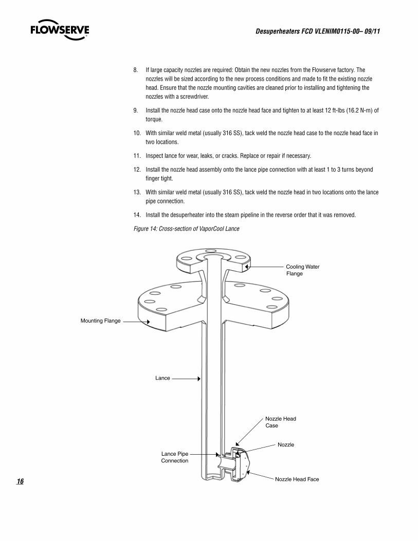
Figure 14: Cross-section of VaporCool Lance
Cooling Water Flange
Nozzle Head Case
Lance Pipe Connection
Mounting Flange
Nozzle
Nozzle Head Face
Lance

17
Desuperheaters FCD VLENIM0115-00 – 09/11
flowserve.com
VaporCool MicroNozzleFollow steps 1-10 to clean or replace the VaporCool MicroNozzle desuperheater.
1. Depressurize the steam line, drain the cooling water line and disconnect the cooling water line from the desuperheater. Remove the desuperheater from the steam line.
2. Carefully grind off the tack weld between the nozzle and the lance pipe connection.
3. Unscrew the nozzle off of the lance pipe connection.
4. With a straight screwdriver, unscrew the orifice insert inside the nozzle.
5. If cleaning is required: With compressed air blow out the passageways of the nozzle and orifice insert. Inspect each part for contamination, blockage, and wear. If necessary replace with new nozzle. Reassemble orifice insert into nozzle and securely tighten with a screwdriver.
6. If different capacity nozzles are required: Obtain the new nozzles from the Flowserve factory.
7. Inspect lance for wear, leaks, or cracks. Replace or repair if necessary.
8. Install the nozzle onto the lance pipe connection with at least 1 to 3 turns beyond finger tight.
9. With similar weld metal (usually 316 SS), tack weld the nozzle onto the lance pipe connection.
10. Install the desuperheater into the steam pipeline in the reverse order that it was removed.
MAINTENANCE (MANIFOLD MOUNTED)Maintenance of manifold mounted desuperheater nozzles may be required if:
• A degradation in cooling efficiency is noted while maintaining constant steam process conditions. This may be an indication that the nozzles are partially plugged.
• The steam process conditions change. If the steam load increases, the nozzles may need to be upsized to keep the downstream steam at the required temperature.
MaxCool MCXFollow steps 1-10 and refer to Figures 2 through 4 to clean or replace the MaxCool MCX desuperheater nozzle.
1. Depressurize the steam and cooling water lines. Drain the cooling water line. Remove cap flange bolting from nozzle housing and remove nozzle housing cap flange. Remove nozzle seat retainer with nozzle assembly. Remove gaskets.
2. Carefully grind off the tack welds between the nozzle assembly and the nozzle seat retainer.
3. Unscrew the nozzle assembly off of the nozzle seat retainer.
4. Remove expansion pin from plug. Unscrew castle nut. The MCX 025 has a regular nut and bent washer in place of a castle nut and expansion pin. Unscrew retainer and remove spring. Remove plug from seat.
5. If cleaning is required: With compressed air blow out the passageways of the nozzle openings and clean the seat and plug surfaces. Inspect parts for wear, contamination, and blockage. Replace if worn or broken.
Desuperheaters FCD VLENIM0115-00– 09/11
18
6. Inspect manifold for wear, leaks, or cracks. Replace or repair if necessary.
7. To reassemble nozzle assembly install plug through seat. Install spring and screw on retainer. Set maximum stroke of plug by screwing retainer until dimensions A and B are met as shown in Figure 12 and Table 5. After maximum stroke is set with retainer, screw on castle nut to lock retainer posi-tion and reinsert expansion pin through plug. Be careful to retain stroke dimension during castle nut and expansion pin assembly. On MCX 025 bend washer to lock nut.
8. Install the nozzle assembly onto the nozzle seat retainer with torque values shown in Table 5.
9. Apply tack weld in two places to face of nozzle seat retainer by flats of nozzle assembly seat. The tack weld should create bumps by the flats to keep nozzle assembly from unscrewing. Care should be used to not apply weld to nozzle assembly seat. See Figure 13.
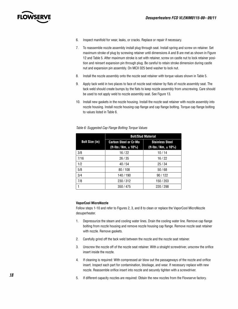
10. Install new gaskets in the nozzle housing. Install the nozzle seat retainer with nozzle assembly into nozzle housing. Install nozzle housing cap flange and cap flange bolting. Torque cap flange bolting to values listed in Table 6.
Table 6: Suggested Cap Flange Bolting Torque Values
Bolt Size (in)Bolt/Stud Material
Carbon Steel or Cr-Mo(ft-lbs / Nm, ± 10%)
Stainless Steel(ft-lbs / Nm, ± 10%)
3/8 16 / 22 10 / 14
7/16 26 / 35 16 / 22
1/2 40 / 54 25 / 34
5/8 80 / 108 50 / 68
3/4 140 / 190 90 / 122
7/8 230 / 312 150 / 203
1 350 / 475 220 / 298
VaporCool MicroNozzleFollow steps 1-10 and refer to Figures 2, 3, and 8 to clean or replace the VaporCool MicroNozzle desuperheater.
1. Depressurize the steam and cooling water lines. Drain the cooling water line. Remove cap flange bolting from nozzle housing and remove nozzle housing cap flange. Remove nozzle seat retainer with nozzle. Remove gaskets.
2. Carefully grind off the tack weld between the nozzle and the nozzle seat retainer.
3. Unscrew the nozzle off of the nozzle seat retainer. With a straight screwdriver, unscrew the orifice insert inside the nozzle.
4. If cleaning is required: With compressed air blow out the passageways of the nozzle and orifice insert. Inspect each part for contamination, blockage, and wear. If necessary replace with new nozzle. Reassemble orifice insert into nozzle and securely tighten with a screwdriver.
5. If different capacity nozzles are required: Obtain the new nozzles from the Flowserve factory.

19
Desuperheaters FCD VLENIM0115-00 – 09/11
flowserve.com
6. Inspect manifold for wear, leaks, or cracks. Replace or repair if necessary.
7. Install the nozzle onto the nozzle seat retainer. Tighten 1 to 3 turns beyond finger tight.
8. With similar weld metal (usually 316 SS), tack weld the nozzle onto the nozzle seat retainer.
9. Install new gaskets in the nozzle housing. Install the nozzle seat retainer with nozzle into nozzle housing. Install nozzle housing cap flange and cap flange bolting. Torque cap flange bolting to values listed in Table 6.

flowserve.com
To find your local Flowserve representative:
For more information about Flowserve Corporation, visit www.flowserve.com or call USA 1 800 225 6989
Flowserve Corporation has established industry leadership in the design and manufacture of its products. When properly selected, this Flowserve product is designed to perform its intended function safely during its useful life. However, the purchaser or user of Flowserve products should be aware that Flowserve products might be used in numerous applications under a wide variety of industrial service conditions. Although Flowserve can (and often does) provide general guidelines, it cannot provide specific data and warnings for all possible applications. The purchaser/user must therefore assume the ultimate responsibility for the proper sizing and selection, installation, operation, and maintenance of Flowserve products. The purchaser/user should read and understand the Installation Operation Maintenance (IOM) instructions included with the product, and train its employees and contractors in the safe use of Flowserve products in connection with the specific application.
While the information and specifications contained in this literature are believed to be accurate, they are supplied for informative purposes only and should not be considered certified or as a guarantee of satisfactory results by reliance thereon. Nothing contained herein is to be construed as a warranty or guarantee, express or implied, regarding any matter with respect to this product. Because Flowserve is continually improving and upgrading its product design, the specifications, dimensions and information contained herein are subject to change without notice. Should any question arise concerning these provisions, the purchaser/user should contact Flowserve Corporation at any one of its worldwide operations or offices.
© 2011 Flowserve Corporation, Irving, Texas, USA. Flowserve is a registered trademark of Flowserve Corporation.
FCD VLENIM0115-00 09/11 Printed in USA.
Flowserve CorporationFlow Control
Flowserve America 1350 N. Mt. Springs Pkwy. Springville, UT 84663 USA Telephone: +1 801 489 8611 Fax: +1 801 489 3719
Flowserve EMA Kasernengasse 6 Villach Austria 9500 Telephone: +43 (0) 4242 41181 0 Fax: +43 (0) 4242 41181 50
Flowserve S.r.L FCD Italy Via Prealpi 30/32 20032 Cormano (MI)Tel. +39 (0)2 66325.1Fax +39 (0)2 66325560