user instructions maintenance instructions installation ... · user instructions maintenance...
TRANSCRIPT
BESTLINK INTERNATIONAL User instructions Maintenance instructions Installation & service instructions Cooktop models: BLGSW905CF BLGSW905C
BLGSW705CF BLGSW705C
BLGSW704CF BLGSW704C
BLGSW60CF BLGSW60C
BLGS60CF BLGS60C
BLGS60EF BLGS60E
BLGSW60EF BLGSW60E
BLGSW30CF BLGSW30C
GMK 10023 AS 4551
This cooktop is approved for use with Natural and Propane gases. Leave instructions with the owner.

2
Table of content
Table of content -----------------------------------2
Introducing your new cooktop -----------------3 Dear customer ---------------------------------------3 Notes on disposal ------------------------------------3 Gas supply--------------------------------------------3 Electrical supply ------------------------------------3 What to do if you smell gas -----------------------3 Safety considerations-------------------------------4 Warnings: --------------------------------------------4
User instructions ----------------------------------5 Burner operation and ignition -------------------5 Manual ignition -------------------------------------6 Ventilation--------------------------------------------6 Abnormal operation--------------------------------6
Cleaning the cooktop -----------------------------7 Preventative maintenance-------------------------7
Installation instructions -------------------------7 Installer instructions -------------------------------7 Statutory requirements ----------------------------7 Overall dimensions ---------------------------------8 Installation dimensions & clearances -----------8
Installation procedure ---------------------------9 Gas connection --------------------------------------9 Boiling burner adjustments--------------------- 10 Energy consumption ----------------------------- 10 Electrical connection ----------------------------- 10 Warranty warning-------------------------------- 10
Conversion --------------------------------------- 11 Propane Gas to Natural Gas-------------------- 11 Natural Gas to Propane ------------------------- 11
Trouble shooting -------------------------------- 12
Service--------------------------------------------- 13 To replace injectors------------------------------- 13 To remove hob------------------------------------- 13 To remove and service gas control valves---- 13 To replace the thermocouple ------------------- 13 To replace the spark electrode ----------------- 13 To replace the electronic ignition module--- 13 To replace internal wiring and gas control ignition micro switch ----------------------------- 13 Wiring diagrams ---------------------------------- 13 Data plates------------------------------------------ 14 For service and spare parts contact: ---------- 14

3
Models Model numbers with the ‘F’ extension are fitted with flame failure device. BLGSW60CF, BLGSW60C (cast iron pan sup-ports. Shown below) BLGSW60EF, BLGSW60E (enamel pan supports)
BLGS60EF & BLGS60E (enamel pan supports, shown below) BLGS60CF & BLGS60C (cast iron pan supports)
BLGSW705CF & BLGSW705C
BLGSW704CF & BLGSW704C
BLGSW905CF & BLGSW905C
BLGSW30CF & BLGSW30C
Introducing your new cooktop Dear customer
Thank you for having purchased one of our pro-ducts. We are certain that this new modern, functional and practical appliance, built with the very highest quality materials, will meet your requirements in the best possible way. This appliance is easy to use, it is however important to thoroughly read the instruc-tions in this manual, in order to obtain the best re-sults. These instructions are only valid for Australia. We shall not be held responsible for any damages to persons or property caused by incorrect installation or use of the appliance. We shall not be held responsible for any inaccura-cies in this manual due to printing or transcription errors; the designs in the figures are purely indica-tive. We also reserve the right to make modifications to the products as may be considered necessary or useful, also in the interest of the user, without jeop-ardising the main functional and safety features of the products themselves These instructions cover 6 cooktops of varying cook-top burner configurations. All cooktops are fitted with a stainless steel hob, electronic spark ignition. Model numbers with the ‘F’ extension are fitted with flame failure device. Please consult the instructions pertaining to your individual cooktop as they are described in these instructions. The cooktop’s data plate is accessible even with the cooktop fully installed. It is positioned on the bottom of the unit. A duplicate copy is supplied at the back of this instruction manual. Always quote the details from it to identify the appliance when ordering spare parts or requesting a service. ♦ In case of malfunction, turn off the cooktop’s
gas supply before contacting the service centre for assistance.
♦ Only an authorized person should connect and service this appliance.
Notes on disposal
Old appliances still have some residual value. En-sure an environmental means of disposal in order for valuable raw materials to be recovered and used again. Please dispose of packaging materials appropri-ately.
Gas supply
Check that the data plate shows the appliance is suitable for the available gas.
Electrical supply
This appliance requires connection to a 10 Amp wall socket.
What to do if you smell gas
♦ Do not try and light the appliance. ♦ Do not touch any electrical switches; do not use
4
a phone in your building. ♦ Immediately call your gas supplier from a neigh-
bour’s phone. Follow the gas supplier’s instruc-tions.
♦ If you cannot reach your gas supplier, call the fire department.
Safety considerations
If the information in this manual is not followed ex-actly, a fire or explosion may result, causing property damage, personal injury or death. ♦ Be sure to disconnect the electrical supply be-
fore disassembly of the appliance. ♦ Never leave the appliance unattended when
cooking with fat or oil. It could ignite if over-heated.
♦ In case of defect, switch electric power off at the mains.
♦ Never use an appliance that is not working cor-rectly.
♦ Only ignite the gas burners when all the burner components are correctly assembled.
♦ Leads from electrical appliances must not touch the cooktop. They will melt and the cable insula-tion will be damaged.
♦ Do not allow the flame to extend beyond the edge of the cooking utensil. This instruction is based on safety considerations.
♦ Do not forget that the unit becomes hot when in use. Common sense is important. Just because the flame is out, does not mean that the parts cannot still be hot.
♦ Small children must be kept at a safe distance from the appliance.
♦ Keep the appliance area clear and free from combustible materials.
♦ Note: To avoid jeapordising the electrical safety of the appliance, it is forbidden to use high-pressure or steam jet cleaning devices.
♦ Cabinets installed above the gas cooktop must have a minimum clearance of 650 mm (24”).
♦ Important. ♦ When using a very large pot, leave a gap of at
least 50 mm (2”) to avoid damaging parts in bench top wood, plastic or other non-heat re-sistant materials. Never leave oil of hot fat unat-tended.
♦ Never leave the appliance unattended when the burners are being used. Make sure there are no children in the near vicinity. Particularly make sure that the pan handle are correctly positioned and keep a check on foods requiring oil and grease to cook since these products can easily catch fire.
♦ Don’t use pans with buckled bottoms
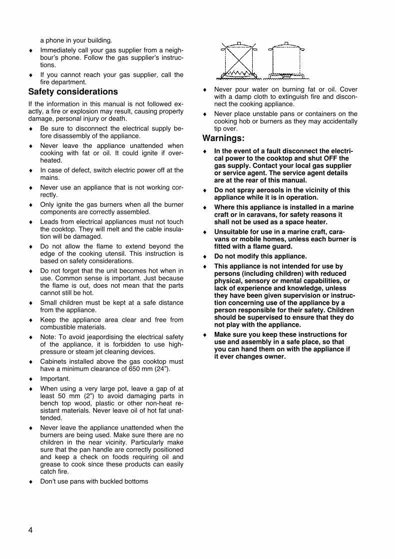
♦ Never pour water on burning fat or oil. Cover
with a damp cloth to extinguish fire and discon-nect the cooking appliance.
♦ Never place unstable pans or containers on the cooking hob or burners as they may accidentally tip over.
Warnings:
♦ In the event of a fault disconnect the electri-cal power to the cooktop and shut OFF the gas supply. Contact your local gas supplier or service agent. The service agent details are at the rear of this manual.
♦ Do not spray aerosols in the vicinity of this appliance while it is in operation.
♦ Where this appliance is installed in a marine craft or in caravans, for safety reasons it shall not be used as a space heater.
♦ Unsuitable for use in a marine craft, cara-vans or mobile homes, unless each burner is fitted with a flame guard.
♦ Do not modify this appliance.
♦ This appliance is not intended for use by persons (including children) with reduced physical, sensory or mental capabilities, or lack of experience and knowledge, unless they have been given supervision or instruc-tion concerning use of the appliance by a person responsible for their safety. Children should be supervised to ensure that they do not play with the appliance.
♦ Make sure you keep these instructions for use and assembly in a safe place, so that you can hand them on with the appliance if it ever changes owner.

5
User instructions The lay-outs of the 5 cooktops covered in these in-structions are shown below. Please check the model number of your particular cooktop to identify your lay-out. Model No’s: BLGSW60CF & BLGSW60C (cast iron pan supports). Model No’s BLGSW60EF & BLGSW60E (enamel pan supports)
1. Triple ring (wok) burner 2. Semi-rapid boiling burner 3. Auxiliary boiling burner 4. Cast iron pan support 5. Right front boiling burner control knob 6. Right rear boiling burner control knob 7. Left rear boiling burner control knob 8. Left front boiling burner control knob Model No’s: BLGS60CF & BLGS60C (cast iron pan supports) Model No’s BLGS60EF & BLGS60E (enamel pan supports)
1. Rapid boiling burner 2. Semi-rapid boiling burners 3. Auxiliary boiling burner 4. Wire pan support or cast iron pan support 5. Right front boiling burner control knob 6. Right rear boiling burner control knob 7. Left rear boiling burner control knob 8. Left front boiling burner control knob Model No: BLGSW705CF & BLGSW705C
1. Rapid boiling burner 2. Semi-rapid boiling burners 3. Auxiliary boiling burner 4. Triple ring (wok) burner 5. Cast iron pan support 6. Left front boiling burner control knob 7. Left rear boiling burner control knob 8. Central triple ring (wok) burner control knob 9. Right rear boiling burner control knob 10. Right front boiling burner control knob
Model No: BLGSW704CF & BLGSW704C
1. Rapid boiling burner 2. Semi-rapid boiling burner 3. Triple ring (wok) burner 4. Auxiliary boiling burner 5. Cast iron pan support 6. Left boiling burner control knob 7. Central rear boiling burner 8. Central front boiling burner 9. Right boiling burner
Model No: BLGSW905CF & BLGSW905C
1. Rapid boiling burner 2. Semi-rapid boiling burners 3. Auxiliary boiling burner 4. Triple ring (wok) burner 5. Cast iron pan support 6. Left front boiling burner control knob 7. Left rear boiling burner control knob 8. Central triple ring (wok) burner control knob 9. Right rear boiling burner control knob 10. Right front boiling burner control knob Model No: BLGSW30CF & BLGSW30C
1. Triple ring (wok) burner 2. Semi rapid boiling burner 3. Semi rapid burner control knob 4. Wok burner control knob
6
Burner operation and ignition
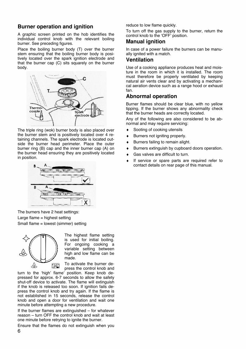
A graphic screen printed on the hob identifies the individual control knob with the relevant boiling burner. See preceding figures. Place the boiling burner body (T) over the burner stem ensuring that the boiling burner body is posi-tively located over the spark ignition electrode and that the burner cap (C) sits squarely on the burner body.
The triple ring (wok) burner body is also placed over the burner stem and is positively located over 4 re-taining channels. The spark electrode is located out-side the burner head perimeter. Place the outer burner ring (B) cap and the inner burner cap (A) on the burner head ensuring they are positively located in position.
The burners have 2 heat settings: Large flame = highest setting Small flame = lowest (simmer) setting
The highest flame setting is used for initial boiling. For ongoing cooking a variable setting between high and low flame can be made. To activate the burner de-press the control knob and
turn to the ‘high’ flame’ position. Keep knob de-pressed for approx. 6-7 seconds to allow the safety shut-off device to activate. The flame will extinguish if the knob is released too soon. If ignition fails de-press the control knob and try again. If the flame is not established in 15 seconds, release the control knob and open a door for ventilation and wait one minute before attempting a new procedure. If the burner flames are extinguished – for whatever reason – turn OFF the control knob and wait at least one minute before retrying to ignite the burner. Ensure that the flames do not extinguish when you
reduce to low flame quickly. To turn off the gas supply to the burner, return the control knob to the ‘OFF’ position.
Manual ignition
In case of a power failure the burners can be manu-ally ignited with a match.
Ventilation
Use of a cooking appliance produces heat and mois-ture in the room in which it is installed. The room must therefore be properly ventilated by keeping natural air vents clear and by activating a mechani-cal aeration device such as a range hood or exhaust fan.
Abnormal operation
Burner flames should be clear blue, with no yellow tipping. If the burner shows any abnormality check that the burner heads are correctly located. Any of the following are also considered to be ab-normal and may require servicing: ♦ Sooting of cooking utensils ♦ Burners not igniting properly. ♦ Burners failing to remain alight. ♦ Burners extinguish by cupboard doors operation. ♦ Gas valves are difficult to turn. ♦ If service or spare parts are required refer to
contact details on rear page of this manual.
7
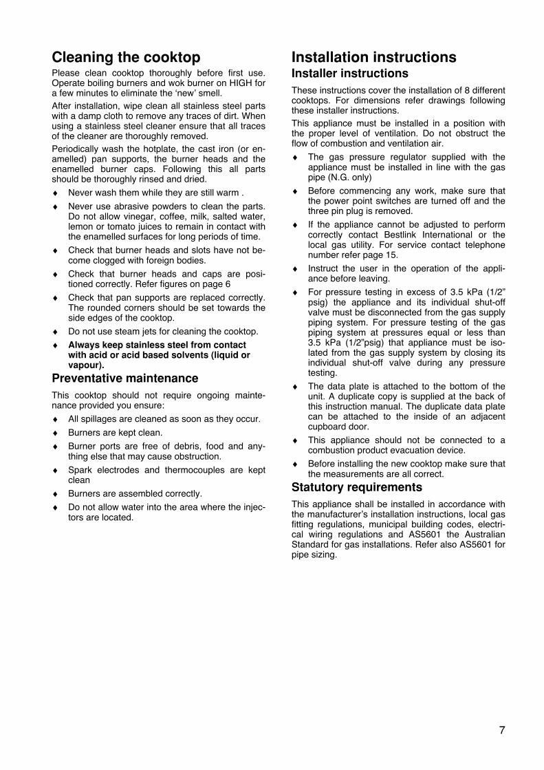
Cleaning the cooktop Please clean cooktop thoroughly before first use. Operate boiling burners and wok burner on HIGH for a few minutes to eliminate the ‘new’ smell. After installation, wipe clean all stainless steel parts with a damp cloth to remove any traces of dirt. When using a stainless steel cleaner ensure that all traces of the cleaner are thoroughly removed. Periodically wash the hotplate, the cast iron (or en-amelled) pan supports, the burner heads and the enamelled burner caps. Following this all parts should be thoroughly rinsed and dried. ♦ Never wash them while they are still warm . ♦ Never use abrasive powders to clean the parts.
Do not allow vinegar, coffee, milk, salted water, lemon or tomato juices to remain in contact with the enamelled surfaces for long periods of time.
♦ Check that burner heads and slots have not be-come clogged with foreign bodies.
♦ Check that burner heads and caps are posi-tioned correctly. Refer figures on page 6
♦ Check that pan supports are replaced correctly. The rounded corners should be set towards the side edges of the cooktop.
♦ Do not use steam jets for cleaning the cooktop. ♦ Always keep stainless steel from contact
with acid or acid based solvents (liquid or vapour).
Preventative maintenance
This cooktop should not require ongoing mainte-nance provided you ensure: ♦ All spillages are cleaned as soon as they occur. ♦ Burners are kept clean. ♦ Burner ports are free of debris, food and any-
thing else that may cause obstruction. ♦ Spark electrodes and thermocouples are kept
clean ♦ Burners are assembled correctly. ♦ Do not allow water into the area where the injec-
tors are located.
Installation instructions Installer instructions
These instructions cover the installation of 8 different cooktops. For dimensions refer drawings following these installer instructions. This appliance must be installed in a position with the proper level of ventilation. Do not obstruct the flow of combustion and ventilation air. ♦ The gas pressure regulator supplied with the
appliance must be installed in line with the gas pipe (N.G. only)
♦ Before commencing any work, make sure that the power point switches are turned off and the three pin plug is removed.
♦ If the appliance cannot be adjusted to perform correctly contact Bestlink International or the local gas utility. For service contact telephone number refer page 15.
♦ Instruct the user in the operation of the appli-ance before leaving.
♦ For pressure testing in excess of 3.5 kPa (1/2” psig) the appliance and its individual shut-off valve must be disconnected from the gas supply piping system. For pressure testing of the gas piping system at pressures equal or less than 3.5 kPa (1/2”psig) that appliance must be iso-lated from the gas supply system by closing its individual shut-off valve during any pressure testing.
♦ The data plate is attached to the bottom of the unit. A duplicate copy is supplied at the back of this instruction manual. The duplicate data plate can be attached to the inside of an adjacent cupboard door.
♦ This appliance should not be connected to a combustion product evacuation device.
♦ Before installing the new cooktop make sure that the measurements are all correct.
Statutory requirements
This appliance shall be installed in accordance with the manufacturer’s installation instructions, local gas fitting regulations, municipal building codes, electri-cal wiring regulations and AS5601 the Australian Standard for gas installations. Refer also AS5601 for pipe sizing.
8
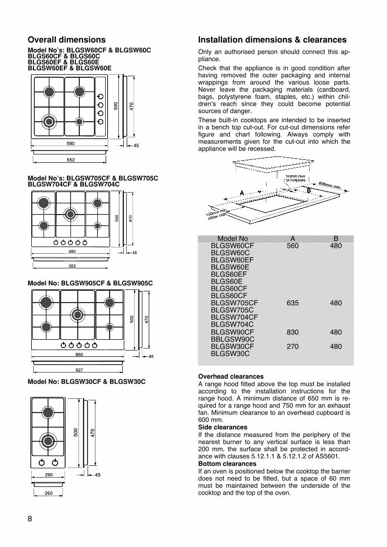
Overall dimensions Model No’s: BLGSW60CF & BLGSW60C BLGS60CF & BLGS60C BLGS60EF & BLGS60E BLGSW60EF & BLGSW60E
Model No’s: BLGSW705CF & BLGSW705C BLGSW704CF & BLGSW704C
Model No: BLGSW905CF & BLGSW905C
Model No: BLGSW30CF & BLGSW30C
Installation dimensions & clearances
Only an authorised person should connect this ap-pliance. Check that the appliance is in good condition after having removed the outer packaging and internal wrappings from around the various loose parts. Never leave the packaging materials (cardboard, bags, polystyrene foam, staples, etc.) within chil-dren’s reach since they could become potential sources of danger. These built-in cooktops are intended to be inserted in a bench top cut-out. For cut-out dimensions refer figure and chart following. Always comply with measurements given for the cut-out into which the appliance will be recessed.
Model No A B BLGSW60CF BLGSW60C BLGSW60EF BLGSW60E BLGS60EF BLGS60E BLGS60CF BLGS60CF
560 480
BLGSW705CF BLGSW705C BLGSW704CF BLGSW704C
635 480
BLGSW90CF BBLGSW90C BLGSW30CF BLGSW30C
830
270
480
480
Overhead clearances A range hood fitted above the top must be installed according to the installation instructions for the range hood. A minimum distance of 650 mm is re-quired for a range hood and 750 mm for an exhaust fan. Minimum clearance to an overhead cupboard is 600 mm. Side clearances If the distance measured from the periphery of the nearest burner to any vertical surface is less than 200 mm, the surface shall be protected in accord-ance with clauses 5.12.1.1 & 5.12.1.2 of AS5601. Bottom clearances If an oven is positioned below the cooktop the barrier does not need to be fitted, but a space of 60 mm must be maintained between the underside of the cooktop and the top of the oven.
9
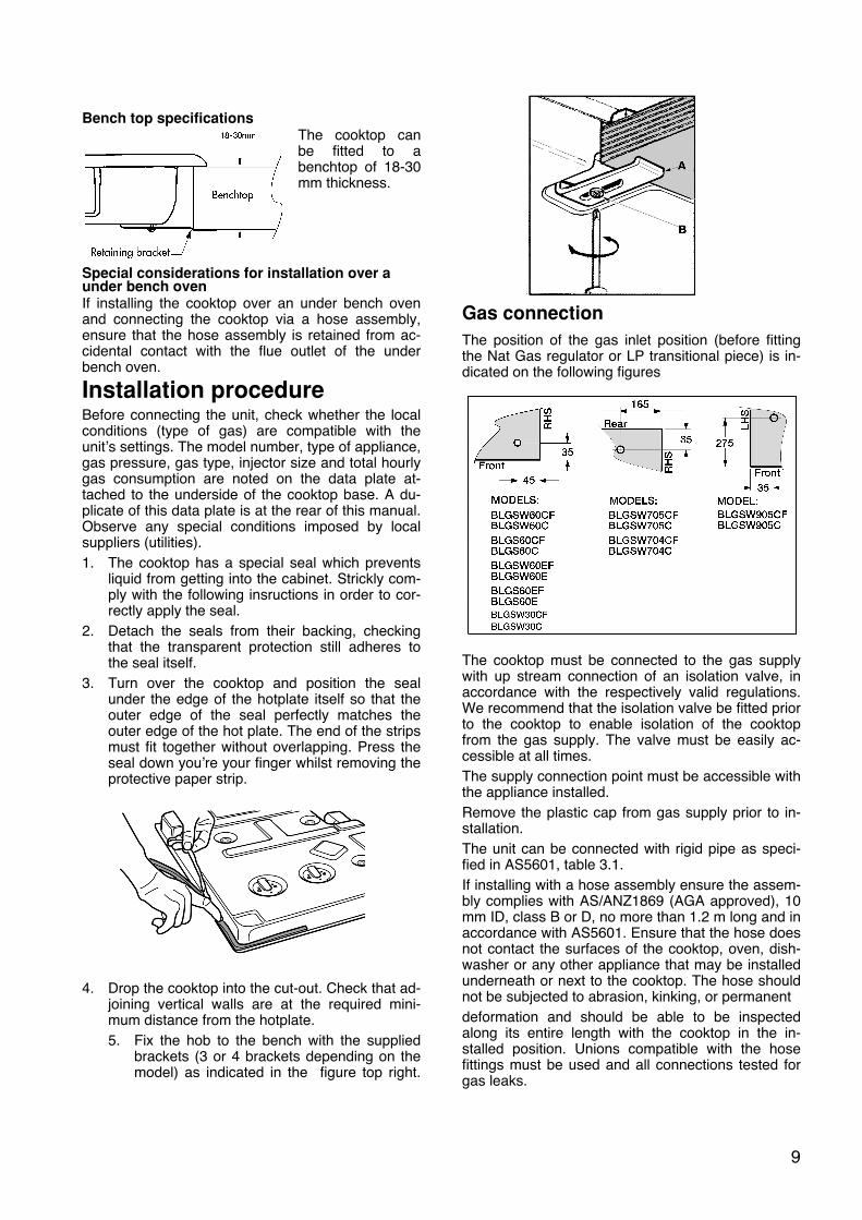
Bench top specifications
The cooktop can be fitted to a benchtop of 18-30 mm thickness.
Special considerations for installation over a under bench oven If installing the cooktop over an under bench oven and connecting the cooktop via a hose assembly, ensure that the hose assembly is retained from ac-cidental contact with the flue outlet of the under bench oven.
Installation procedure Before connecting the unit, check whether the local conditions (type of gas) are compatible with the unit’s settings. The model number, type of appliance, gas pressure, gas type, injector size and total hourly gas consumption are noted on the data plate at-tached to the underside of the cooktop base. A du-plicate of this data plate is at the rear of this manual. Observe any special conditions imposed by local suppliers (utilities). 1. The cooktop has a special seal which prevents
liquid from getting into the cabinet. Strickly com-ply with the following insructions in order to cor-rectly apply the seal.
2. Detach the seals from their backing, checking that the transparent protection still adheres to the seal itself.
3. Turn over the cooktop and position the seal under the edge of the hotplate itself so that the outer edge of the seal perfectly matches the outer edge of the hot plate. The end of the strips must fit together without overlapping. Press the seal down you’re your finger whilst removing the protective paper strip.
4. Drop the cooktop into the cut-out. Check that ad-
joining vertical walls are at the required mini-mum distance from the hotplate. 5. Fix the hob to the bench with the supplied
brackets (3 or 4 brackets depending on the model) as indicated in the figure top right.
Gas connection
The position of the gas inlet position (before fitting the Nat Gas regulator or LP transitional piece) is in-dicated on the following figures
The cooktop must be connected to the gas supply with up stream connection of an isolation valve, in accordance with the respectively valid regulations. We recommend that the isolation valve be fitted prior to the cooktop to enable isolation of the cooktop from the gas supply. The valve must be easily ac-cessible at all times. The supply connection point must be accessible with the appliance installed. Remove the plastic cap from gas supply prior to in-stallation. The unit can be connected with rigid pipe as speci-fied in AS5601, table 3.1. If installing with a hose assembly ensure the assem-bly complies with AS/ANZ1869 (AGA approved), 10 mm ID, class B or D, no more than 1.2 m long and in accordance with AS5601. Ensure that the hose does not contact the surfaces of the cooktop, oven, dish-washer or any other appliance that may be installed underneath or next to the cooktop. The hose should not be subjected to abrasion, kinking, or permanent deformation and should be able to be inspected along its entire length with the cooktop in the in-stalled position. Unions compatible with the hose fittings must be used and all connections tested for gas leaks.
10
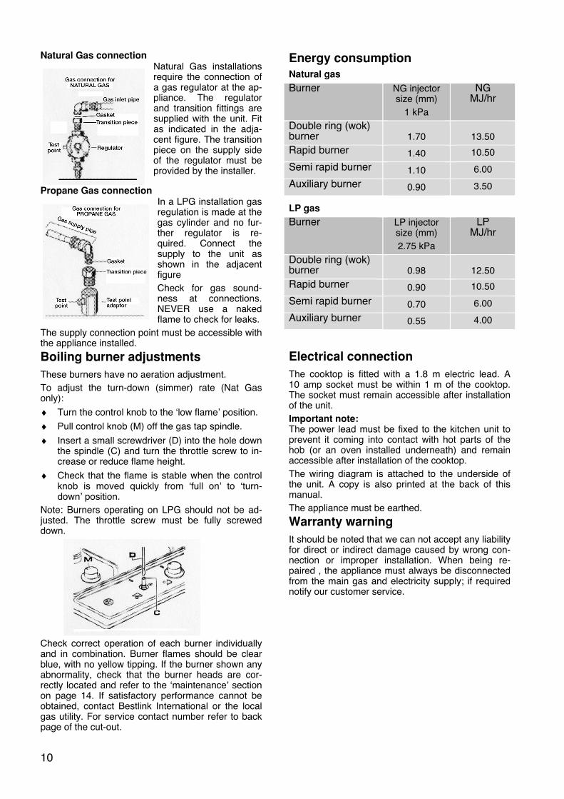
Natural Gas connection Natural Gas installations require the connection of a gas regulator at the ap-pliance. The regulator and transition fittings are supplied with the unit. Fit as indicated in the adja-cent figure. The transition piece on the supply side of the regulator must be provided by the installer.
Propane Gas connection In a LPG installation gas regulation is made at the gas cylinder and no fur-ther regulator is re-quired. Connect the supply to the unit as shown in the adjacent figure Check for gas sound-ness at connections. NEVER use a naked flame to check for leaks.
The supply connection point must be accessible with the appliance installed.
Boiling burner adjustments
These burners have no aeration adjustment. To adjust the turn-down (simmer) rate (Nat Gas only): ♦ Turn the control knob to the ‘low flame’ position. ♦ Pull control knob (M) off the gas tap spindle. ♦ Insert a small screwdriver (D) into the hole down
the spindle (C) and turn the throttle screw to in-crease or reduce flame height.
♦ Check that the flame is stable when the control knob is moved quickly from ‘full on’ to ‘turn-down’ position.
Note: Burners operating on LPG should not be ad-justed. The throttle screw must be fully screwed down.
Check correct operation of each burner individually and in combination. Burner flames should be clear blue, with no yellow tipping. If the burner shown any abnormality, check that the burner heads are cor-rectly located and refer to the ‘maintenance’ section on page 14. If satisfactory performance cannot be obtained, contact Bestlink International or the local gas utility. For service contact number refer to back page of the cut-out.
Energy consumption
Natural gas
Burner NG injector size (mm)
1 kPa
NG MJ/hr
Double ring (wok) burner
1.70
13.50
Rapid burner 1.40 10.50
Semi rapid burner 1.10 6.00
Auxiliary burner 0.90 3.50 LP gas
Burner LP injector size (mm) 2.75 kPa
LP MJ/hr
Double ring (wok) burner
0.98
12.50
Rapid burner 0.90 10.50
Semi rapid burner 0.70 6.00
Auxiliary burner 0.55 4.00
Electrical connection
The cooktop is fitted with a 1.8 m electric lead. A 10 amp socket must be within 1 m of the cooktop. The socket must remain accessible after installation of the unit. Important note: The power lead must be fixed to the kitchen unit to prevent it coming into contact with hot parts of the hob (or an oven installed underneath) and remain accessible after installation of the cooktop. The wiring diagram is attached to the underside of the unit. A copy is also printed at the back of this manual. The appliance must be earthed.
Warranty warning
It should be noted that we can not accept any liability for direct or indirect damage caused by wrong con-nection or improper installation. When being re-paired , the appliance must always be disconnected from the main gas and electricity supply; if required notify our customer service.
11
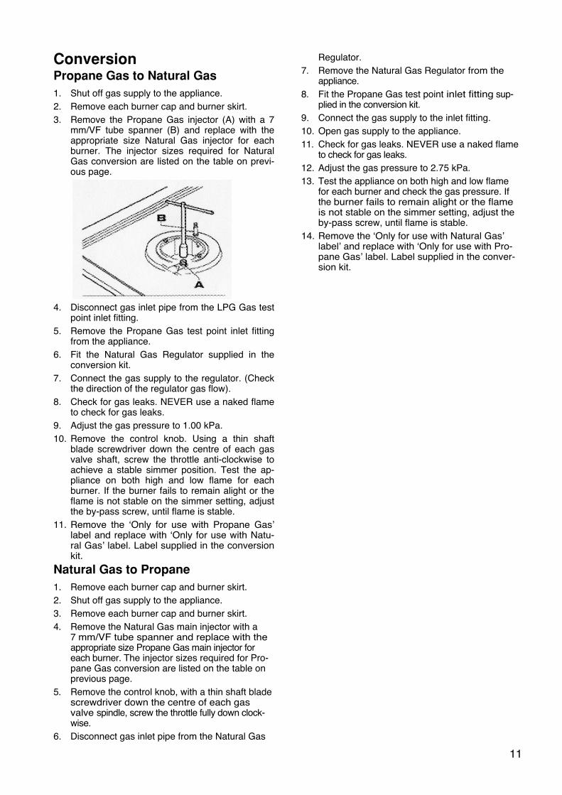
Conversion Propane Gas to Natural Gas
1. Shut off gas supply to the appliance. 2. Remove each burner cap and burner skirt. 3. Remove the Propane Gas injector (A) with a 7
mm/VF tube spanner (B) and replace with the appropriate size Natural Gas injector for each burner. The injector sizes required for Natural Gas conversion are listed on the table on previ-ous page.
4. Disconnect gas inlet pipe from the LPG Gas test
point inlet fitting. 5. Remove the Propane Gas test point inlet fitting
from the appliance. 6. Fit the Natural Gas Regulator supplied in the
conversion kit. 7. Connect the gas supply to the regulator. (Check
the direction of the regulator gas flow). 8. Check for gas leaks. NEVER use a naked flame
to check for gas leaks. 9. Adjust the gas pressure to 1.00 kPa. 10. Remove the control knob. Using a thin shaft
blade screwdriver down the centre of each gas valve shaft, screw the throttle anti-clockwise to achieve a stable simmer position. Test the ap-pliance on both high and low flame for each burner. If the burner fails to remain alight or the flame is not stable on the simmer setting, adjust the by-pass screw, until flame is stable.
11. Remove the ‘Only for use with Propane Gas’ label and replace with ‘Only for use with Natu-ral Gas’ label. Label supplied in the conversion kit.
Natural Gas to Propane
1. Remove each burner cap and burner skirt. 2. Shut off gas supply to the appliance. 3. Remove each burner cap and burner skirt. 4. Remove the Natural Gas main injector with a
7 mm/VF tube spanner and replace with the appropriate size Propane Gas main injector for each burner. The injector sizes required for Pro-pane Gas conversion are listed on the table on previous page.
5. Remove the control knob, with a thin shaft blade screwdriver down the centre of each gas valve spindle, screw the throttle fully down clock-wise.
6. Disconnect gas inlet pipe from the Natural Gas
Regulator. 7. Remove the Natural Gas Regulator from the
appliance. 8. Fit the Propane Gas test point inlet fitting sup-
plied in the conversion kit. 9. Connect the gas supply to the inlet fitting. 10. Open gas supply to the appliance. 11. Check for gas leaks. NEVER use a naked flame
to check for gas leaks. 12. Adjust the gas pressure to 2.75 kPa. 13. Test the appliance on both high and low flame
for each burner and check the gas pressure. If the burner fails to remain alight or the flame is not stable on the simmer setting, adjust the by-pass screw, until flame is stable.
14. Remove the ‘Only for use with Natural Gas’ label’ and replace with ‘Only for use with Pro-pane Gas’ label. Label supplied in the conver-sion kit.
12
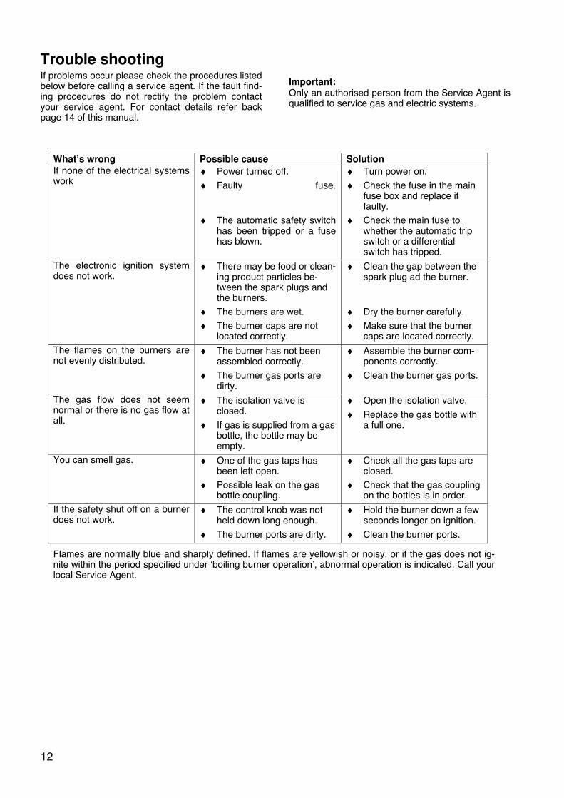
Trouble shooting If problems occur please check the procedures listed below before calling a service agent. If the fault find-ing procedures do not rectify the problem contact your service agent. For contact details refer back page 14 of this manual.
Important: Only an authorised person from the Service Agent is qualified to service gas and electric systems.
What’s wrong Possible cause Solution
If none of the electrical systems work
♦ Power turned off. ♦ Faulty fuse.
♦ The automatic safety switch has been tripped or a fuse has blown.
♦ Turn power on. ♦ Check the fuse in the main
fuse box and replace if faulty.
♦ Check the main fuse to whether the automatic trip switch or a differential switch has tripped.
The electronic ignition system does not work.
♦ There may be food or clean-ing product particles be-tween the spark plugs and the burners.
♦ The burners are wet. ♦ The burner caps are not
located correctly.
♦ Clean the gap between the spark plug ad the burner.
♦ Dry the burner carefully. ♦ Make sure that the burner
caps are located correctly. The flames on the burners are not evenly distributed.
♦ The burner has not been assembled correctly.
♦ The burner gas ports are dirty.
♦ Assemble the burner com-ponents correctly.
♦ Clean the burner gas ports.
The gas flow does not seem normal or there is no gas flow at all.
♦ The isolation valve is closed.
♦ If gas is supplied from a gas bottle, the bottle may be empty.
♦ Open the isolation valve. ♦ Replace the gas bottle with
a full one.
You can smell gas. ♦ One of the gas taps has been left open.
♦ Possible leak on the gas bottle coupling.
♦ Check all the gas taps are closed.
♦ Check that the gas coupling on the bottles is in order.
If the safety shut off on a burner does not work.
♦ The control knob was not held down long enough.
♦ The burner ports are dirty.
♦ Hold the burner down a few seconds longer on ignition.
♦ Clean the burner ports.
Flames are normally blue and sharply defined. If flames are yellowish or noisy, or if the gas does not ig-nite within the period specified under ‘boiling burner operation’, abnormal operation is indicated. Call your local Service Agent.
13
Service THIS APPLIANCE SHALL NOT BE MODIFIED. Service and maintenance should only be carried out by an authorised person.
To replace injectors
Refer page 11.
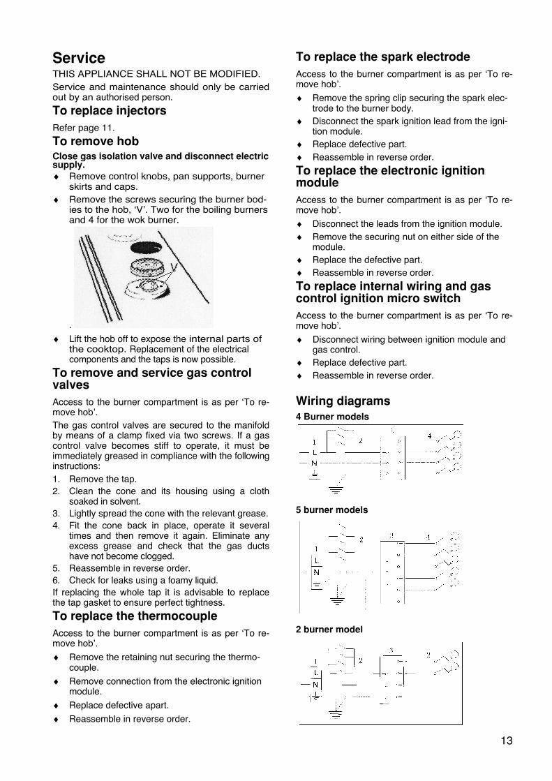
To remove hob Close gas isolation valve and disconnect electric supply.
♦ Remove control knobs, pan supports, burner skirts and caps.
♦ Remove the screws securing the burner bod-ies to the hob, ‘V’. Two for the boiling burners and 4 for the wok burner.
. ♦ Lift the hob off to expose the internal parts of
the cooktop. Replacement of the electrical components and the taps is now possible.
To remove and service gas control valves
Access to the burner compartment is as per ‘To re-move hob’. The gas control valves are secured to the manifold by means of a clamp fixed via two screws. If a gas control valve becomes stiff to operate, it must be immediately greased in compliance with the following instructions: 1. Remove the tap. 2. Clean the cone and its housing using a cloth
soaked in solvent. 3. Lightly spread the cone with the relevant grease. 4. Fit the cone back in place, operate it several
times and then remove it again. Eliminate any excess grease and check that the gas ducts have not become clogged.
5. Reassemble in reverse order. 6. Check for leaks using a foamy liquid. If replacing the whole tap it is advisable to replace the tap gasket to ensure perfect tightness.
To replace the thermocouple
Access to the burner compartment is as per ‘To re-move hob’. ♦ Remove the retaining nut securing the thermo-
couple. ♦ Remove connection from the electronic ignition
module. ♦ Replace defective apart. ♦ Reassemble in reverse order.
To replace the spark electrode
Access to the burner compartment is as per ‘To re-move hob’. ♦ Remove the spring clip securing the spark elec-
trode to the burner body. ♦ Disconnect the spark ignition lead from the igni-
tion module. ♦ Replace defective part. ♦ Reassemble in reverse order.
To replace the electronic ignition module
Access to the burner compartment is as per ‘To re-move hob’. ♦ Disconnect the leads from the ignition module. ♦ Remove the securing nut on either side of the
module. ♦ Replace the defective part. ♦ Reassemble in reverse order.
To replace internal wiring and gas control ignition micro switch
Access to the burner compartment is as per ‘To re-move hob’. ♦ Disconnect wiring between ignition module and
gas control. ♦ Replace defective part. ♦ Reassemble in reverse order.
Wiring diagrams
4 Burner models
5 burner models
2 burner model
14
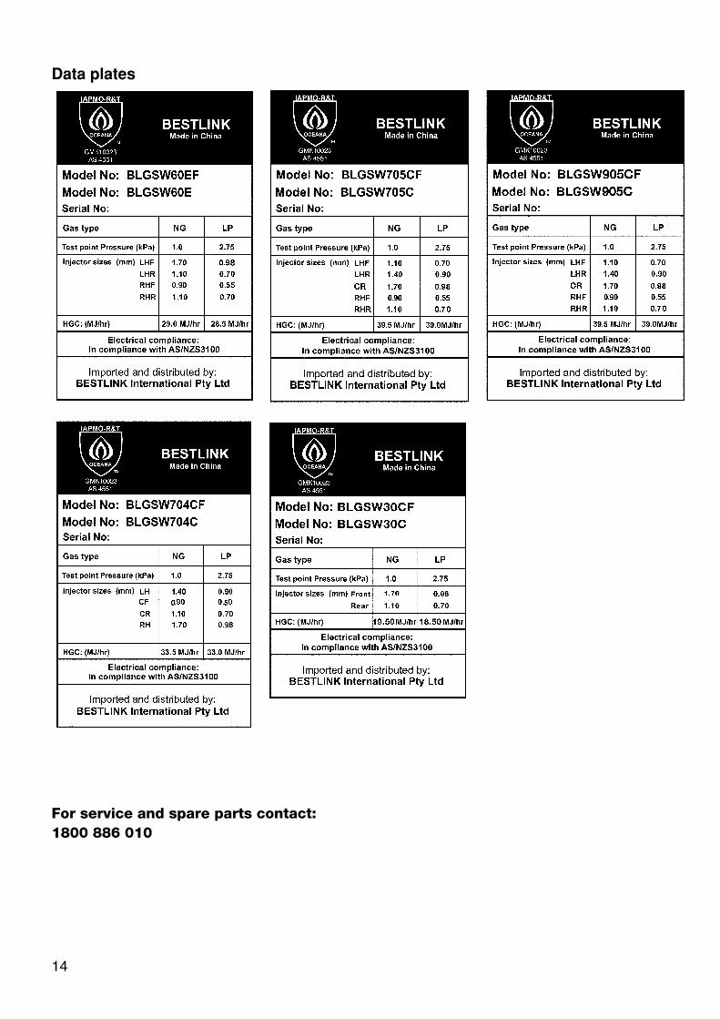
Data plates
For service and spare parts contact:
1800 886 010