user interface design specification - cisco · chapter 2 user interface design specification call...
TRANSCRIPT

C
C H A P T E R 2
User Interface Design SpecificationSeptember 24, 2015
Chapter OverviewThis guide shows the user interface graphics specifications for the touchscreen on the customer pod.
Topics in this chapter include:
• “Home Screen”
• “Call Connecting Screen”
• “Call Connected Screen”
• “Scan Screen”
• “Signature Screen”
• “Thank You Screen”
• “Session Result Screen”
• “Hold Screen”
• “Help Wait Screen”
Home ScreenThe Home screen contains the following images:
• Background
• Expert Type Buttons
• Help Button
• Language Buttons
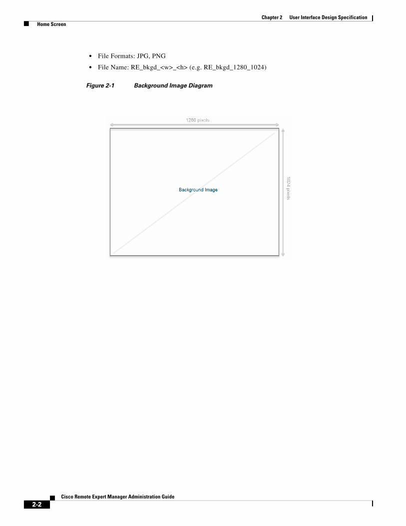
BackgroundThe Background image is used for all the screens.
The background image has the following specifications:
2-1isco Remote Expert Manager Administration Guide
Chapter 2 User Interface Design Specification Home Screen
• File Formats: JPG, PNG
• File Name: RE_bkgd_<w>_<h> (e.g. RE_bkgd_1280_1024)
Figure 2-1 Background Image Diagram
2-2Cisco Remote Expert Manager Administration Guide

Chapter 2 User Interface Design Specification Home Screen
Figure 2-2 Example of Background Image
Expert Type ButtonsThe Home screen can accommodate up to six expert type buttons. These buttons have the following specifications:
File Formats: JPG, PNG
File Name: <name>_<w>_<h> (e.g. commercial_lending_235_235)
2-3Cisco Remote Expert Manager Administration Guide

Chapter 2 User Interface Design Specification Home Screen
Figure 2-3 Expert Type Button Dimensions and Examples
2-4Cisco Remote Expert Manager Administration Guide

Chapter 2 User Interface Design Specification Home Screen
Figure 2-4 Example of Six Expert Type Buttons on the Home Screen
Help and Language ButtonsThe Help button is placed in the lower left corner of the Home screen while the Language buttons (if more than one Locale is available) are placed in the lower right corner of the Home screen. Both buttons have the following specifications:
• File Formats: JPG, PNG
• File Name: <name>_<language>_<w>_<h> (e.g. help_english_220_80)
2-5Cisco Remote Expert Manager Administration Guide

Chapter 2 User Interface Design Specification Home Screen
Figure 2-5 Home Screen Diagram showing Help and Language Button Locations
2-6Cisco Remote Expert Manager Administration Guide

Chapter 2 User Interface Design Specification Call Connecting Screen
Figure 2-6 Example of a Home Screen showing Help and Language Buttons
Note The captions for the expert type images are configured through REAC while adding the expert type. Refer to the “Add an Expert Type” section of Chapter 1.
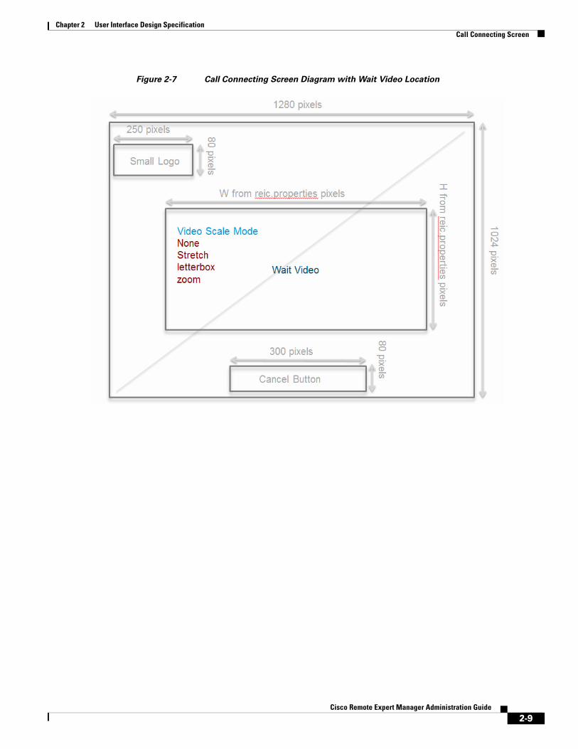
Call Connecting ScreenThe Call Connecting screen contains the following:
• Cancel Button
• Small Logo
• Wait Video or Wait Image or Null
2-7Cisco Remote Expert Manager Administration Guide

Chapter 2 User Interface Design Specification Call Connecting Screen
Cancel Button• File Formats: JPG, PNG
• File Name: <name>_<language>_<w>_<h> (e.g. cancel_english_300_80)
Small LogoThe Small Logo appears in the upper left corner of the Call Connecting screen. It also appears on the Thank You, Session Result, and Hold screens.
• File Formats: JPG, PNG
• File Name: <name>_<size>_<w>_<h> (e.g. logo_small_250_80)
Wait VideoA Wait Video can be played during the Call Connecting screen.
Video size can be configured in the REIC Properties file. To change the videoplayer.scaleMode property, follow these steps.
Step 1 Log into the REM server under the TUI account.
Step 2 In the Main Menu, choose REM Server Administration.
Step 3 In the REM Server Administration menu, choose Edit REM Templates.
Step 4 In the Edit REM Templates menu, choose e) REIC Properties.
The scaleMode property in the REIC Properties file adjusts the size of the playing media after the control size has been set. The scaleMode property only works when you set the height or width property. Possible values are none, stretch, letterbox, and zoom. If you omit both width and height properties for the control, REIC sizes the control to fit the size of the playing media. If you specify only one property, and set the scaleMode property, the size of the playing media determines the value of the other property. If you do not set the scaleMode property, the media retains its aspect ratio when resizing. If you explicitly set the width and height properties, be sure the values are appropriate for the size of video that plays.
2-8Cisco Remote Expert Manager Administration Guide
Chapter 2 User Interface Design Specification Call Connecting Screen
Figure 2-7 Call Connecting Screen Diagram with Wait Video Location
2-9Cisco Remote Expert Manager Administration Guide

Chapter 2 User Interface Design Specification Call Connecting Screen
Figure 2-8 Example of a Call Connecting Screen showing a Wait Video
Wait Image A Wait Image can be displayed during the Call Connecting screen instead of a Wait Video.
File Format: JPG, PNG
File Name: <name>_<language>_<w>_<h> (e.g. connecting_english_500_500)
2-10Cisco Remote Expert Manager Administration Guide

Chapter 2 User Interface Design Specification Call Connecting Screen
Figure 2-9 Call Connecting Screen Diagram with Wait Image Location
2-11Cisco Remote Expert Manager Administration Guide

Chapter 2 User Interface Design Specification Call Connecting Screen
Figure 2-10 Example of a Call Connecting Screen showing a Wait Image
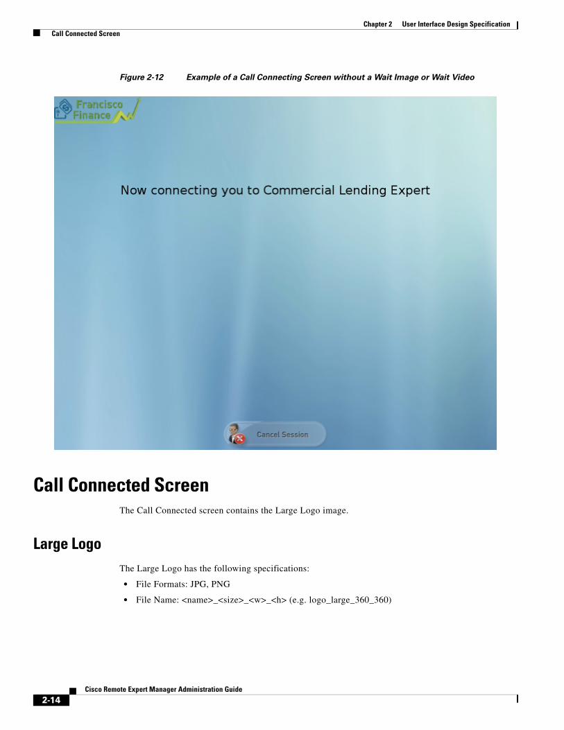
NullIf no Wait Image or Wait Video is desired, the center of the screen can be left blank.
2-12Cisco Remote Expert Manager Administration Guide

Chapter 2 User Interface Design Specification Call Connecting Screen
Figure 2-11 Call Connecting Screen Diagram without Wait Image or Wait Video
2-13Cisco Remote Expert Manager Administration Guide
Chapter 2 User Interface Design Specification Call Connected Screen
Figure 2-12 Example of a Call Connecting Screen without a Wait Image or Wait Video
Call Connected ScreenThe Call Connected screen contains the Large Logo image.
Large LogoThe Large Logo has the following specifications:
• File Formats: JPG, PNG
• File Name: <name>_<size>_<w>_<h> (e.g. logo_large_360_360)
2-14Cisco Remote Expert Manager Administration Guide

Chapter 2 User Interface Design Specification Call Connected Screen
Figure 2-13 Call Connected Screen Diagram
2-15Cisco Remote Expert Manager Administration Guide

Chapter 2 User Interface Design Specification Scan Screen
Figure 2-14 Example of a Call Connected Screen
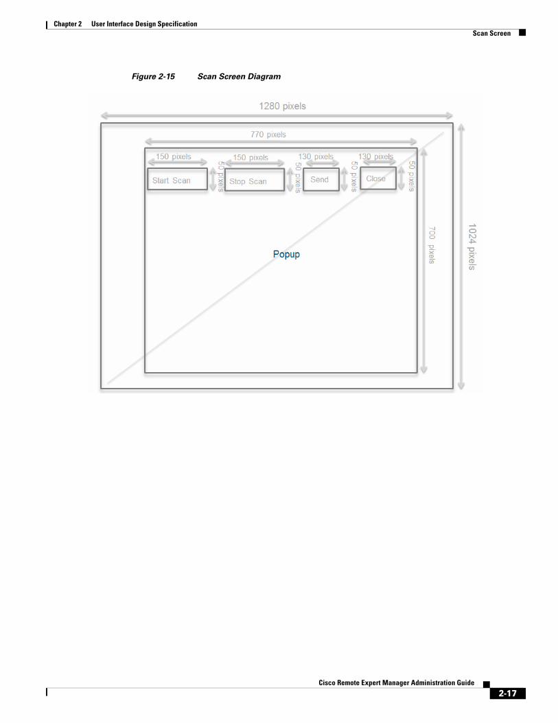
Scan ScreenWhen the agent launches the Scan collaboration feature, the Scan screen appears on the customer pod. The buttons for the Scan screen can be customized.
File Format: JPG, PNG
File Name: <name>_<language>_<w>_<h> (e.g. start_english_150_50, send_spanish_130_50)
2-16Cisco Remote Expert Manager Administration Guide
Chapter 2 User Interface Design Specification Scan Screen
Figure 2-15 Scan Screen Diagram
2-17Cisco Remote Expert Manager Administration Guide

Chapter 2 User Interface Design Specification Signature Screen
Figure 2-16 Example of a Scan Screen
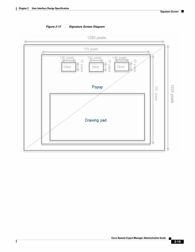
Signature ScreenWhen the agent launches the Signature collaboration feature, the Signature screen appears on the customer pod. The buttons for the Signature screen can be customized.
File Format: JPG/PNG
File Name: <name>_<language>_<w>_<h> (e.g. clear_english_130_50)
2-18Cisco Remote Expert Manager Administration Guide
Chapter 2 User Interface Design Specification Signature Screen
Figure 2-17 Signature Screen Diagram
2-19Cisco Remote Expert Manager Administration Guide
Chapter 2 User Interface Design Specification Thank You Screen
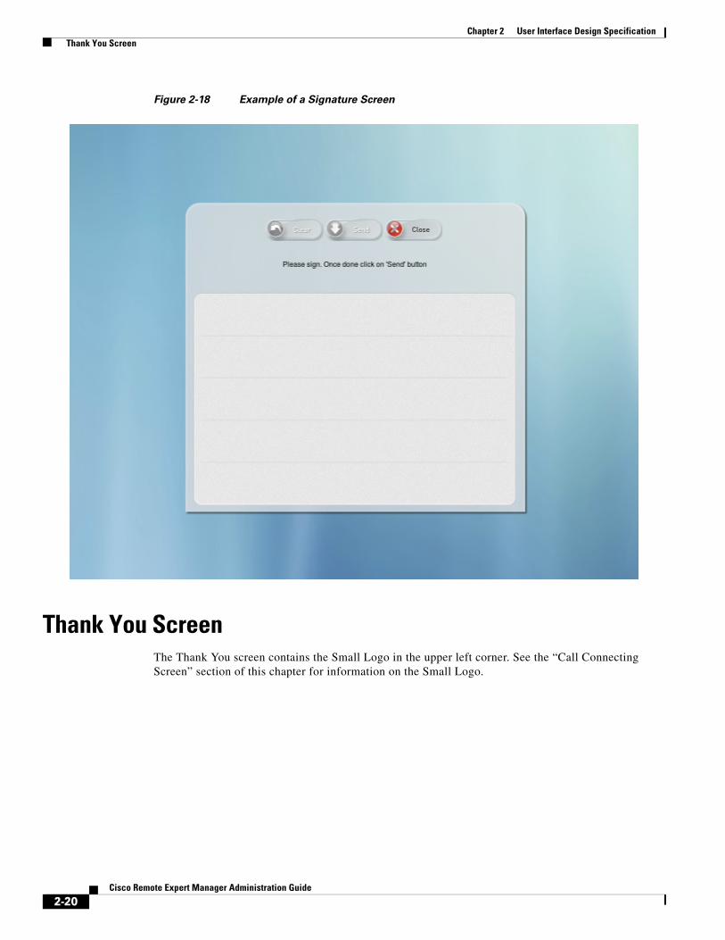
Figure 2-18 Example of a Signature Screen
Thank You ScreenThe Thank You screen contains the Small Logo in the upper left corner. See the “Call Connecting Screen” section of this chapter for information on the Small Logo.
2-20Cisco Remote Expert Manager Administration Guide

Chapter 2 User Interface Design Specification Thank You Screen
Figure 2-19 Thank You Screen Diagram
2-21Cisco Remote Expert Manager Administration Guide

Chapter 2 User Interface Design Specification Session Result Screen
Figure 2-20 Example of a Thank You Screen
Session Result ScreenThe Session Result screen is similar to the Thank You screen in that it contains the Small Logo in the upper left corner.
2-22Cisco Remote Expert Manager Administration Guide

Chapter 2 User Interface Design Specification Session Result Screen
Figure 2-21 Session Result Screen Diagram
2-23Cisco Remote Expert Manager Administration Guide

Chapter 2 User Interface Design Specification Hold Screen
Figure 2-22 Example of a Session Result Screen
Hold ScreenThe Hold screen contains the Hold video and the Small Logo image.
2-24Cisco Remote Expert Manager Administration Guide

Chapter 2 User Interface Design Specification Hold Screen
Figure 2-23 Hold Screen Diagram
2-25Cisco Remote Expert Manager Administration Guide

Chapter 2 User Interface Design Specification Help Wait Screen
Figure 2-24 Example of a Hold Screen Streaming the On Hold Video
Help Wait ScreenThe Help Wait screen contains the Small Logo image.
2-26Cisco Remote Expert Manager Administration Guide

Chapter 2 User Interface Design Specification Help Wait Screen
Figure 2-25 Help Wait Screen Diagram
2-27Cisco Remote Expert Manager Administration Guide

Chapter 2 User Interface Design Specification Help Wait Screen
Figure 2-26 Example of a Help Wait Screen
2-28Cisco Remote Expert Manager Administration Guide