user manual
TRANSCRIPT

90-NET
UNINTERRUPTIBLE POWER SYSTEM
Restricted Sales Destribution
Warning: This is a product for Restricted Sales Distribution to informed partners. TheUPS may give rise to radio-frequency interference affecting other equipment in the vi-cinity; it is advised that the UPS not be positioned next to devices which, by their nature,are sensitive to such interference (receivers/transmitters, radar, metal detectors, anti-theft systems) and that cabling of such devices be kept separate from that of the UPS
wherever possible. It is also advised that the UPS input, output and external battery cables behoused in earthed, metal conduits, or that shielded cables be used.
USER MANUAL10H52168UM01 - Rev. 3

CHLORIDE 90-NET
Page 2 User Handbook - 10H52168UM01 - rev. 3 - 03/2006
Copyright © Chloride UPS Systems, 2006
All rights, including rights of translation, reproduction by printing, copying or similar methods, even of parts, are reserved.
Offenders will be liable for damages.
All rights, including rights created by patent grant or registration of utility model or design, are reserved.
Delivery subject to availability. Right of technical mod-ification reserved.
ENG

CHLORIDE 90-NET
User Handbook - 10H52168UM01 - rev. 3 - 03/2006 Page 3
1. About these operation instructions ...............................................................................92. Safety ................................................................................................................................103. Equipment delivery and storage ...................................................................................133.1. Transportation ......................................................................................................................... 133.2. Storage ...................................................................................................................................... 134. Installation preparations ...............................................................................................174.1. Unpacking ................................................................................................................................. 174.2. Transporting without packaging materials ........................................................................ 174.3. Selecting an installation site ................................................................................................ 174.4. Placement ................................................................................................................................. 185. Installation .......................................................................................................................195.1. Installation data ....................................................................................................................... 196. Power and signal connections .....................................................................................316.1. Power connections ................................................................................................................. 316.2. Cable lengths ........................................................................................................................... 336.3. Backfeed Protection ............................................................................................................... 336.4. 60-80kVA UPS power connections ...................................................................................... 346.5. 100-120kVA UPS power connections .................................................................................. 356.6. 160-200kVA power connections ........................................................................................... 366.7. 250/300kVA UPS power connections .................................................................................. 376.8. 400kVA UPS power connections .......................................................................................... 386.9. 500kVA UPS power and signal connections ...................................................................... 396.10. 600/800kVA power and signal connections ..................................................................... 406.11. Signal connections ............................................................................................................... 446.12. Individual UPS signal connection information ................................................................ 457. Battery connections .......................................................................................................477.1. Battery cabinet connections ................................................................................................. 487.2. Battery calculation settings .................................................................................................. 518. Parallel ..............................................................................................................................638.1. Installation - COC .................................................................................................................... 638.2. Power and signal connections - COC .................................................................................. 678.3. 400/800A COC Power connections ....................................................................................... 698.4. 1600A COC Power connections ............................................................................................ 708.5. 3200A COC Power connections ............................................................................................ 718.6. Parallel signal connections .................................................................................................. 729. System description .........................................................................................................799.1. Function ..................................................................................................................................... 799.2. Special features ...................................................................................................................... 819.3. Block diagram .......................................................................................................................... 82

CHLORIDE 90-NET
Page 4 User Handbook - 10H52168UM01 - rev. 3 - 03/2006
9.4. Switch positions and corresponding operating modes ...................................................829.5. Operating modes ......................................................................................................................839.6. Protection devices ...................................................................................................................8910. Operation ........................................................................................................................9110.1. Control Panel and display ....................................................................................................9110.2. Inverter STOP/START procedures ......................................................................................9210.3. Controls and messages .........................................................................................................9410.4. Warning and Fault indications ............................................................................................9910.5. Troubleshooting ...................................................................................................................10211. COC control panel .......................................................................................................10311.1. Control panel ........................................................................................................................10411.2. 90-net diagnostics for parallel system with COC ...........................................................10411.3. COC messages normal condition ......................................................................................10511.4. Desription of COC system stages ......................................................................................11011.5. COC RESERVE stage description .......................................................................................11211.6. COC UPS stage description ................................................................................................11311.7. LOAD stage description ......................................................................................................11412. Operating procedures .................................................................................................11512.1. Sample guided procedure - Manual Bypass ..................................................................11612.2. CENTRALISED parallel system ..........................................................................................12012.3. Parallel operation ................................................................................................................12712.4. Guided procedure ................................................................................................................12813. I/O functions .................................................................................................................13313.1. List of Individual functions for single and modular parallel UPS ...............................13313.2. List of individual COC functions ........................................................................................13513.3. I/O Function setting via PC terminal .................................................................................13613.4. Description of function wiring with fixed terminal assignments ...............................14013.5. Electrical specifications of input/output signals ...........................................................14213.6. Table of functions ................................................................................................................14313.7. I/O functions using interfaces X7 and X8 .........................................................................14614. Interfaces ......................................................................................................................14914.1. Standard interface COM - X6 .............................................................................................15014.2. Computer Relay Interface - X7 ...........................................................................................15014.3. PPVis configured service interface - X3 ..........................................................................15014.4. X8 - Load Isolating Device (option) ...................................................................................15015. Standard equipment ...................................................................................................15115.1. Device parameter special setting .....................................................................................15115.2. Battery parameter setting ..................................................................................................15115.3. Special colour ......................................................................................................................151

CHLORIDE 90-NET
User Handbook - 10H52168UM01 - rev. 3 - 03/2006 Page 5
15.4. Further accessories ............................................................................................................ 15115.5. PPVis ...................................................................................................................................... 15116. Options ..........................................................................................................................15216.1. Remote alarm unit ............................................................................................................... 15216.2. External battery circuit breaker ....................................................................................... 15216.3. Additional RFI filters (only upon request) ....................................................................... 15216.4. IP 31 with air filter cartridge ............................................................................................. 15216.5. Battery leakage alarm ........................................................................................................ 15216.6. Battery Management Modules (only upon request) ..................................................... 15216.7. Isolation transformer .......................................................................................................... 15216.8. Top cable entry .................................................................................................................... 15216.9. Dust filters ............................................................................................................................ 15216.10. Input harmonic filters for 6 pulse versions (only upon request) ............................... 15316.11. 12 Pulse rectifier ................................................................................................................ 15316.12. Multiple Bus Synchronization Module (MBSM) ......................................................... 15316.13. Empty battery cubicle ....................................................................................................... 15316.14. Battery cubicles ................................................................................................................ 15416.15. Empty options cubicle ...................................................................................................... 15416.16. Customer interface board ................................................................................................ 15416.17. Telephone switch for LIFE.net ........................................................................................ 15416.18. MopUPS Shutdown and monitoring software ............................................................. 15416.19. ManageUPS adapter ......................................................................................................... 15416.20. PPVIS surveys Monitoring Software ............................................................................. 15516.21. Compatibility Table ........................................................................................................... 15516.22. J-Bus protocol ................................................................................................................... 15516.23. Profi Bus protocol ............................................................................................................. 15517. Maintenance ................................................................................................................15717.1. Maintenance intervals ....................................................................................................... 15717.2. Service addresses ............................................................................................................... 15718. Environmental compatibility, disposal ....................................................................15718.1. Environmental concerns during development ............................................................... 15718.2. Environmental concerns during production .................................................................. 15718.3. Environmental concerns for disposal .............................................................................. 157

CHLORIDE 90-NET
Page 6 User Handbook - 10H52168UM01 - rev. 3 - 03/2006

CHLORIDE 90-NET
User Handbook - 10H52168UM01 - rev. 3 - 03/2006 Page 7
Fig. 1 - Transporting the UPS ..................................................................................................14Fig. 2 - Width between forks ...................................................................................................15Fig. 3 - Permissible load dependent on installation altitude ...............................................18Fig. 4 - Dimensions of UPS rating 60 and 80kVA ..................................................................20Fig. 5 - Dimensions of UPS rating 100 and 120kVA ..............................................................21Fig. 6 - Dimensions of UPS ratings 160 and 200kVA .............................................................22Fig. 7 - Dimensions of UPS ratings 250, 300 and 400kVA .....................................................23Fig. 8 - Roof - 250/300/400kVA .................................................................................................24Fig. 9 - Dimensions of UPS rating 500kVA .............................................................................25Fig. 10 - Dimensions of UPS ratings 600/800kVA ..................................................................26Fig. 11 - Cubicle footprint - 60 - 200kVA ................................................................................27Fig. 12 - Cubicle footprint - 250/300/400kVA ..........................................................................28Fig. 13 - Cubicle footprint 500kVA ..........................................................................................29Fig. 14 - Cubicle footprint - 600/800kVA .................................................................................30Fig. 15 - Two mains supplies ...................................................................................................33Fig. 16 - 60-80kVA UPS connections ......................................................................................34Fig. 17 - 100-120kVA UPS connections ..................................................................................35Fig. 18 - 160-200kVA UPS connections ..................................................................................36Fig. 19 - 250/300UPS connections ...........................................................................................37Fig. 20 - 400kVA UPS connections ..........................................................................................38Fig. 21 - 500kVA UPS power connections ..............................................................................39Fig. 22 - 600/800kVA power connections - Input cubicle .....................................................40Fig. 23 - 600/800kVA power connections - Output cubicle ..................................................41Fig. 24 - Output cubicle connection points ............................................................................42Fig. 25 - Busbar connections ...................................................................................................43Fig. 26 - Plaited power cables .................................................................................................43Fig. 27 - Battery connection diagram .....................................................................................49Fig. 28 - Sample battery autonomy calculation ....................................................................52Fig. 29 - Dimensions of COC rating 400/800/3200A ...............................................................64Fig. 30 - Dimensions of COC rating 1600A .............................................................................65Fig. 31 - C.O.C. footprints ........................................................................................................66Fig. 32 - COC 400/800A .............................................................................................................69Fig. 33 - COC 1600A ..................................................................................................................70Fig. 34 - COC 3200A ..................................................................................................................71Fig. 35 - POB mounting location .............................................................................................73Fig. 36 - POB interconnection diagram ..................................................................................74Fig. 37 - Inserting the shielding clamp ...................................................................................74Fig. 38 - Removing the shielding clamp .................................................................................74Fig. 39 - Connections and loop circuit (25-pin plug) for example 4-block system .............75Fig. 40 - UPS On-line Double Conversion operation .............................................................79Fig. 41 - Overview UPS components ......................................................................................82Fig. 42 - Power flow in on-line operation ...............................................................................83Fig. 43 - Power flow in battery operation ..............................................................................83Fig. 44 - Power flow in reserve operation ..............................................................................84Fig. 45 - Power flow in service bypass operation .................................................................84Fig. 46 - Power flow during battery test ................................................................................84Fig. 47 - Power flow in frequency converter operation ........................................................85Fig. 48 - Centralised parallel system electrical connections - 400/800A .............................85Fig. 49 - Centralised parallel system electrical connections - 1600/3200A .........................86Fig. 50 - Centralised parallel system electrical connections ................................................87Fig. 51 - Distributed parallel system electrical connections ................................................88Fig. 52 - Control Panel ..............................................................................................................93Fig. 53 - System block, main- and submenus ........................................................................94Fig. 54 - COC control panel ....................................................................................................103Fig. 55 - Connections for modular parallel system .............................................................127Fig. 56 - PPVis - page [3] Contacts ........................................................................................146Fig. 57 - Connectivity panel ...................................................................................................149Fig. 58 - Location of connectivity panel ...............................................................................149

CHLORIDE 90-NET
Page 8 User Handbook - 10H52168UM01 - rev. 3 - 03/2006

ABOUT THESE OPERATION INSTRUCTIONS CHLORIDE 90-NET
User Handbook - 10H52168UM01 - rev. 3 - 03/2006 Page 9
1. ABOUT THESE OPERATION INSTRUCTIONS
Who are these operating instructions intended for?These operating instructions are intended for use by qualified personnel involved in the transport, installation,commissioning, maintenance and operation of the 90-NET devices.
Symbols usedThe following symbols are used in this handbook:
Terms usedMaintenance bypassThe switch that allows maintenance work to be carried out without interrupting the supply to the load.
Electronic bypassA thyristor switch which connects the load directly to mains in event of inverter overload; also referred to asa static switch or static bypass.
Qualified personnelPersonnel who are familiar with the installation, assembly, commissioning and operation of the product andare qualified to carry out the respective activities.
DisplayAn LCD display, providing information about the operating status of the UPS.
EC Declaration of ConformityThe 90-NET System (UPS device with battery cabinet) is in conformity with the protection and safety objec-tives of the following European directives:
73/23/ECDirective of the council for adaptation of the legal regulations of the member states regarding electrical equip-ment for use within specific voltage limits, modified by directive 93/68/EC.
89/336/ECDirective of the council for adaptation of the legal regulations of the member states regarding electromagneticcompatibility, modified by directive 91/263/EC, 92/31/EC and 93/68/EC.Conformity is established through compliance with the following standards:·EN 62040-1-2·EN 50091-2·IEC/EN 62040-3
DangerAs defined by these operating instructions and the danger notices on the products. Failureto observe the appropriate safety measures will result in death, severe injury or consider-able damage to property.
WarningAs defined by these operating instructions and the warning notices on the products. Fail-ure to carry out described operations or observe proper precautions may result in death,severe injury or considerable damage to property.
NoticeThis pictogram draws attention to important information about the product or part of theoperating instructions.
Indicates a step that must be carried out

CHLORIDE 90-NET SAFETY
Page 10 User Handbook - 10H52168UM01 - rev. 3 - 03/2006
2. SAFETY
Intended useThis device serves as an uninterruptible power supply for connected loads.It complies with all relevant safety regulations governing information technology equipment.
Safety Notices
Emergency measures
NoticeThis UPS may only be installed in closed operating areas. If the area contains or if there is present inthe area, any equipment containing in excess of 25 litres of inflammable liquids, refer to HD384.4.42 S1 A2, chapter 42 (corresponds to DIN VDE 0100, Part 420), it must be ensured that burn-ing liquids or their combustion products cannot spread through the building.
Carefully read the following safety notices!
WarningDangerous voltages are present within the device when in operation, failure to comply with thewarning notices may result in death, severe injury, or considerable damage to property. It is impor-tant to note, also, that when the EPO (Emergency Power Off) is in operation, i.e. the unit has beenautomatically switched off due to some dangerous fault condition, battery power is still presentwithin the UPSThis device must be installed, connected, commissioned, maintained and repaired byqualified personnel. These personnel must be familiar with all repair and maintenance tasksdescribed in these operating instructions. Error-free and safe operation of this device requires propertransport, storage, placement, installation and connection, as well as careful operation and mainte-nance.
DangerMains over-voltage:this UPS must be protected against over-voltages deriving from the mains sup-ply.The device was developed in accordance with the product normative EN 50091-2, which relatesto the IEC 1000-4-5. Over-voltages must be planned for in the power supply system, including thosecaused by lightning strikes as well as those produced internally as the result of switching inductiveor capacitive loads, such as power transformers or capacitor banks, or as the result of short-circuitshutdowns.
In addition to the warning notices given in the respective sections, pay particular attention to the following notices:
• When selecting a location for the device and before operation, observe the notices concerning environmental conditions.• When disconnecting the mains voltage, the connected loads continue to be sup-plied with voltage by the battery, and return voltage is present at the input terminals of the UPS.• During thunderstorms, data transfer cables must not be connected or discon-nected.• Ensure that no objects (e.g. drilling chips, screws etc.) are left inside of the device.
In an emergency, immediately carry out the following steps:• Open the external mains separation device.• Switch off the load.• Put out any fires with an extinguisher appropriate for the batteries being used.• Never attempt to extinguish a fire with water since the batteries carry voltage.

SAFETY CHLORIDE 90-NET
User Handbook - 10H52168UM01 - rev. 3 - 03/2006 Page 11
Danger Areas
For reasons of safety the Operator MUST NOT REMOVE the secondary access panel.If, for any reason, it is necessary to remove this panel, the installation must be switched offand de-energised, otherwise complete safety cannot be guaranteed.
When the UPS is closed, parts which carry voltage must not be touched. After removing the protective panelsor terminal field covering, the connection terminals and rails, as well as exposed metal parts and other com-ponents carrying dangerous voltages are no longer protected against accidental contact!When working on an open UPS device, the corresponding safety measures must be observed. The followingdanger is present even with disconnected UPS:
DangerThe UPS contains capacitors which continue to store energy for a period of time after the device hasbeen disconnected from the mains supplies and battery. This voltage (> 500 V DC) is present at bat-tery terminals C+ and D-. For this reason, check that the UPS and the external mains separationdevice are switched off and the battery fuses removed. Before continuing work, measure the volt-age at the battery terminals and at the mains input filter and wait until this has dropped to 0 V. Fail-ure to do this can lead to severe electrical shock and even death.
Notice90-NET has been designed for installation in TN-S and TN-C systems. Please contact your distributerif you are uncertain about your installation.For installation in permanent IT systems please contact CHLORIDE Technical Support.

CHLORIDE 90-NET SAFETY
Page 12 User Handbook - 10H52168UM01 - rev. 3 - 03/2006

EQUIPMENT DELIVERY AND STORAGE CHLORIDE 90-NET
User Handbook - 10H52168UM01 - rev. 3 - 03/2006 Page 13
3. EQUIPMENT DELIVERY AND STORAGE
3.1. Transportation
All UPS cabinets are delivered on transport pallets:
• 60/80 kVA Transport pallet 1000 x 1000 mm (w x d). The pallet raises the UPS device by approx.
200 mm.
• 100/120 kVA Transport pallet 1200 x 1000 mm (w x d). The pallet raises the UPS device by approx.
200 mm
• 160/200 kVA Transport pallet 1600 x 1000 mm (w x d). The pallet raises the UPS device by approx.
200 mm.
• 250/300/400 kVA Transport pallet 1800 x 1000 mm (w x d). The pallet raises the UPS device by approx.
200 mm.
• 500 kVA Transport pallet 2000 x 1000 mm (w x d). The pallet raises the UPS device by approx.
200 mm.
• .600/800 kVA 2 x Transport pallets 1800 x 1000 mm (w x d). The pallet raises the UPS device by approx. 200 mm.
3.2. Storage
If the UPS and battery cabinets are not to be installed immediately, they may be kept in storage. Observe thefollowing:
• Store the UPS and battery cabinets in their original packaging.• The storage conditions described in the appendix must be observed.• Batteries must be recharged at least once every three months. If battery cabinets are to be stored for longer then three months before installation, ensure that they are recharged regularly during this period.• Pay attention to the times given for recharging the batteries. These values are given on a sticker on the device or on the packaging.
WarningPay attention to the markings indicating the centre of gravity of the device. Use suitable means oftransportation and secure the UPS against tipping over when transporting. Improper transportationcan result in damage to the UPS and battery cabinet as well as injury to personnel.
Transport the UPS and battery cabinets to the storage or installation site on the pallet inthe original packaging, using a suitable lifting truck or crane, (see Fig. 1 and Fig. 2), if acrane is used, insert lifting beams to ensure the unit is not damaged (see step “a”).When moving the 250/300/400 and 500kVA ratings it is possible to use two forklifts,inserting one at each side. In the case of the 250/300/400/600/800kVA ratings there are two central feet (see Fig. 12- on page 28 and Fig. 14 - on page 30) which may obstruct the forks. (See Table 19 onpage 15).In the case of the 500kVA there is a continuous foot in the middle of the cabinet (see Fig.12 - on page 28) which may obstruct the forks. (See Table 19 on page 15).

CHLORIDE 90-NET EQUIPMENT DELIVERY AND STORAGE
Page 14 User Handbook - 10H52168UM01 - rev. 3 - 03/2006
Figure 1 - Transporting the UPS

EQUIPMENT DELIVERY AND STORAGE CHLORIDE 90-NET
User Handbook - 10H52168UM01 - rev. 3 - 03/2006 Page 15
Figure 2 - Width between forks
Table 19: Forklift clearance dimensions
UPS Model (kVA) COC Ratings (A)
max dimensions of
60/80
100/120
160/200
250/300/400
500 600/800a)
a) The 600/800 ratings consist of two cubicles, the measurements refer to the individual cubicles.
400/800
1600
a (mm) 150 150 150 150 100b)
b) Note lower forklift clearance than for other ratings.
150 150 150
bc) (mm)
c) For 60 - 200kVA ratings pay attention to the centre foot when inserting the forks (see Fig. 11 - on page 27.For 250/300/400 and 500kVA ratings, two forklifts must be used, paying attention to the supports under the centre of the unit when inserting the forks (see Fig. 12 - on page 28 and Fig. 13 - on page 29).
510 510 510 600 600 600 600 600
cd) (mm)
d) For 250/300/400/500/600 and 800kVA ratings pay attention to the supports under the centre of the unit when inserting the forks (see Fig. 12 - on page 28 and Fig. 13 - on page 29).
560 760 760 575 + 575 1540
(770 + 770)e)
e) If at all possible, the UPS should be lifted by inserting the forks at the side (b); if it is necessary to lift it by inserting the forks at the front or rear, open the front panels to avoid bending them. When lifting from the front or rear, use adjustable width forks, or two forklifts - do not attempt to lift using a single, fixed-width forklift.
575 + 575 760 560
d (mm) 150 150 150 150 150 150 150 150
ab
c
d

CHLORIDE 90-NET EQUIPMENT DELIVERY AND STORAGE
Page 16 User Handbook - 10H52168UM01 - rev. 3 - 03/2006

INSTALLATION PREPARATIONS CHLORIDE 90-NET
User Handbook - 10H52168UM01 - rev. 3 - 03/2006 Page 17
4. INSTALLATION PREPARATIONS
4.1. Unpacking
4.2. Transporting without packaging materials
The cabinets can easily be moved to their final destinations with lifting devices.
4.3. Selecting an installation site
Pay attention to the following conditions when selecting an installation site:
4.3.1. Ambient temperatureThe ambient temperature should be between 0°C and +40°C for UPS devices. For continuous operation attemperatures up to a maximum of +50°C, the maximum load must be reduced by 12 % of the nominal loadper 5°C.The ambient temperature should be between +15°C and +25°C for battery cabinets.
NoticeThe device should be unpacked at the installation site since the packaging provides additional pro-tection during transportation
Unpack the device as follows:• Check the UPS and battery cabinet for physical damage and in the event of prob-lems, inform the forwarding agent and if necessary, your CHLORIDE agent.• Check the nameplates on the UPS and battery cabinet against the delivery papersand your order. The nameplate can be viewed with front door open. It is also attachedto the packaging.• Loosen the fastening screws on the pallet.• Slowly lift the cabinets from the pallet; depending on the weight 2 or 3 peopleshould be at hand (see Fig. 1 and Fig. 2).• Keep the pallet for repackaging or transportation at a later time.
Dispose of the remaining packaging material in accordance with local regulations
WarningStones, or irregularities in the floor can block the fork lift. Moving the cabinets too quickly can dam-age them, causing them to fall over and injure personnel.
NoticeThis UPS must only be installed in closed operating areas. If the area contains, or if there is presentin the area, any equipment containing in excess of 25 litres of inflammable fluids, refer to HD384.4.42 S1 A2, chapter 42 (corresponds to DIN VDE 0100, Part 420), it must be ensured that burn-ing fluids or their combustion products cannot spread through the building.
Be sure to provide sufficient cooling of the installation room so that the ambient tempera-ture remains within the stated limits. The heat emission ratings of the UPS are given in the Appendix. Be sure also to provide sufficient ventilation for the type of batteries used in the UPS.

CHLORIDE 90-NET INSTALLATION PREPARATIONS
Page 18 User Handbook - 10H52168UM01 - rev. 3 - 03/2006
4.3.2. Installation altitudeWhen operating the 90-NET UPS at altitudes above 1000m a.s.l., the load must be reduced in accordancewith Fig. 3. If the ambient temperature remains less than +30°C, no load reduction is necessary for altitudesup to 2000 m.
Figure 3 - Permissible load dependent on installation altitude
4.3.3. FloorBe sure that the load carrying capacity of the floor is sufficient for the UPS and batteries. The floor must beeven and level.
4.3.4. Environmental conditionsAvoid harmful environmental conditions such as:
• vibration• dust• corrosive atmospheres• high humidity
4.3.5. Space requirementsProvide the following minimum distances:
• minimum of 50 cm between the top of the cabinet and the roof• no wall-distance if the cable is run through a double floor, otherwise the wall-distance must be at least equal to the bending radius of the cables in use. The distance between covering parts and floor is 150 mm.• no limitations on either side of the device
4.4. Placement
DangerWhenever the devices are moved they must be secured against sideways tipping
70
1000
90
80
100
2000 3000

INSTALLATION CHLORIDE 90-NET
User Handbook - 10H52168UM01 - rev. 3 - 03/2006 Page 19
5. INSTALLATION
5.1. Installation data
• Ambient temperature.............................................................................................0 + 40°C• Relative humidity (w/o condensation @ 20°C).............................................................. 90%• Max. altitude (w/o derating) .............................................................................1000 m.a.s.l.• Protection degree (with doors open)............................................................................. IP20• Cable entry ....................................................................................................bottom or side• Air inlet ......................................................................................................................bottom• Air outlet..........................................................................................................................top
Table 20: UPS installation data
Description U.M.
UPS Ratings kVA60 80 100 120 160 200
Dimensionssee: Fig. 4 Fig. 5 Fig. 6
on page 20 21 22
Weighta) (6 step)
a) +/- 25 kg
kg 595 615 700 1050
Weighta) (12 step)
kg 850 900 985 1480
Floor loading (6 step)
kg/m2 930 770 875 940
Floor loading (12 step)
kg/m2 1330 1125 1230 1320
Air flow of fans m3/h 1800 2700 3600
Max. dissipation (@nominal load
and battery recharging)
(kW)
(kcal/h)
4.4
3786
5.8
4990
6.8
5851
8.1
6969
10
8604
12.6
10842
Max. audible noise level (@1m) dBA 62 64 65
Description U.M.UPS Ratings kVA
250 300 400 500 600 800Dimensions
see: Fig. 7 and Fig. 8 Fig. 9 Fig. 10on page 23 and 24 25 26
Weighta) (12 step)
kg 1860 2095 2495 I/P 2000O/P 2050
Floor loading (12 step)
kg/m2 1455 1640 1560 I/P 1530O/P 1570
Air flow of fans m3/h 5400 7200 15300
Max. dissipation (@nominal load
and battery recharging)
(kW)
(kcal/h)
18.7
16086
21.1
18156
27.9
24006
34.8
29940
45.6
39230
60.8
52305
Max. audible noise level (@1m) dBA 68 70 72 75
STANDARD FINISH: LIGHT GREY RAL 7035

CHLORIDE 90-NET INSTALLATION
Page 20 User Handbook - 10H52168UM01 - rev. 3 - 03/2006
Figure 4 - Dimensions of UPS rating 60 and 80kVA
1780
150
838
858
838
822
810
35
215
298 2985
800
800
ROOF
Air outlet grids
BASE
180°
INSTALLATION CHLORIDE 90-NET
User Handbook - 10H52168UM01 - rev. 3 - 03/2006 Page 21
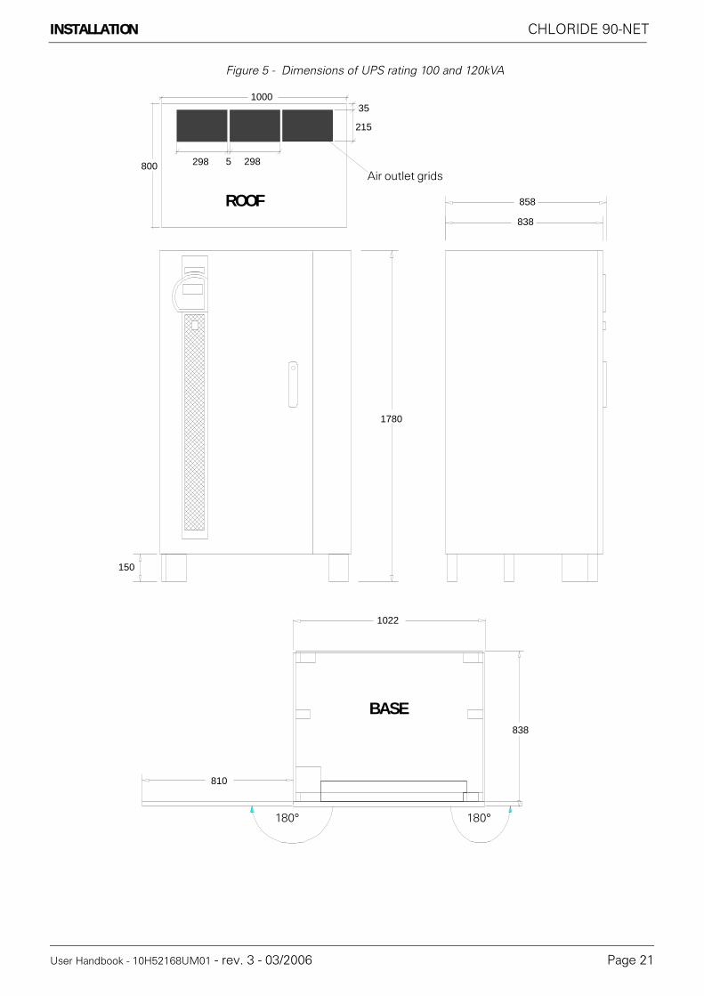
Figure 5 - Dimensions of UPS rating 100 and 120kVA
35
215
298 2985
1000
800
1780
150
838
858
838
1022
810
ROOF
Air outlet grids
BASE
180° 180°

CHLORIDE 90-NET INSTALLATION
Page 22 User Handbook - 10H52168UM01 - rev. 3 - 03/2006
Figure 6 - Dimensions of UPS ratings 160 and 200kVA
35
215
298 2985
1400
800
1780
150
838
838
600
1422
810
858ROOF
Air outlet grids
BASE
180° 180°

INSTALLATION CHLORIDE 90-NET
User Handbook - 10H52168UM01 - rev. 3 - 03/2006 Page 23
Figure 7 - Dimensions of UPS ratings 250, 300 and 400kVA
1780
150
1622
838
810
838
858
800BASE
180° 180°

CHLORIDE 90-NET INSTALLATION
Page 24 User Handbook - 10H52168UM01 - rev. 3 - 03/2006
Figure 8 - Roof - 250/300/400kVA
250/300kVA
400kVA
XT1 XT2
XT1 XT2
Air outlet grids

INSTALLATION CHLORIDE 90-NET
User Handbook - 10H52168UM01 - rev. 3 - 03/2006 Page 25
Figure 9 - Dimensions of UPS rating 500kVA
9
XT2XT1
1780
2022
838
858
10001010
Air outlet grids
ROOF
BASE
180° 180°

CHLORIDE 90-NET INSTALLATION
Page 26 User Handbook - 10H52168UM01 - rev. 3 - 03/2006
Figure 10 - Dimensions of UPS ratings 600/800kVA
*1 - Input cubicle only shown - the output cubicle is identical, but without XT1 and XT2 terminal blocks*2 - Input cubicle only shown - the output cubicle is identical, but without the display on the front left panel.*3 - The busbars for interconnection with the output cubicle protrude beyond the width of the input cubicle (which is supplied without a right side panel); the overall width of the UPS is equal to the width of the two cubicles, installed side by side, plus 30 mm interconnection space = 3252mm.*4 - The external front panels (I/P cubicle left, and O/P cubicle right) can be opened through 180°, whereas the internal front panels (I/P cubicle right, and O/P cubicle left) can only be opened through 135°.
838
MAX 858
1780
808.5
1611
807.5
*1
*2*3
*4
XT1
XT2

INSTALLATION CHLORIDE 90-NET
User Handbook - 10H52168UM01 - rev. 3 - 03/2006 Page 27
Figure 11 - Cubicle footprint - 60 - 200kVA
83
70
25
70
45
305
387
70
25
70
45
305
25
445
105 105
50
255
50
395
5050
190
255
50
255
50
80 80
135
60/80kVA = 822
11 11
11
30
100/120kVA = 1022160/200kVA = 1422
60/80kVA = 660100/120kVA = 860160/200kVA = 1260
Input cable gland plate.60/80kVA = 574 x 94 mm100kVA = 777 x 104 mm120kVA = 777 x 109 mm160/200kVA = 1175 x 135 mm
1) Footprint
2) Floor mounting holes (diameter = 12mm)

CHLORIDE 90-NET INSTALLATION
Page 28 User Handbook - 10H52168UM01 - rev. 3 - 03/2006
Figure 12 - Cubicle footprint - 250/300/400kVA
150
100
725150725
325
100
155
100
120
1622
838
11 11
11
30
684
58
146070
Input cable gland plate = 1290 x 165 mm
1) Footprint
2) Floor mounting holes (diameter = 12mm)

INSTALLATION CHLORIDE 90-NET
User Handbook - 10H52168UM01 - rev. 3 - 03/2006 Page 29
Figure 13 - Cubicle footprint 500kVA
50615
50
1690 155155
5530ø14
12095
225
120120
120120
115
80 80
80 80
25
25 302022
1800
100
100
11
100
11
8080
8080
Input cable gland plate = 1800 x 140 mm
1) Footprint
2) Floor mounting holes (diameter = 14mm)

CHLORIDE 90-NET INSTALLATION
Page 30 User Handbook - 10H52168UM01 - rev. 3 - 03/2006
Figure 14 - Cubicle footprint - 600/800kVA
3252
105.530.01351
30.030.0
1351
30.0
51
720
67
51720
67
838
16111611
105.5
ø12
167
100
30100
11
50
160
31050
50
100100
150
15011
80
660 505
150 150
150150
30
1063
150
150
11
3252
15
3105080
15
771 760
Input cable gland plates
1) Footprint
2) Floor mounting holes (diameter = 12mm)
Input cable gland plate

POWER AND SIGNAL CONNECTIONS CHLORIDE 90-NET
User Handbook - 10H52168UM01 - rev. 3 - 03/2006 Page 31
6. POWER AND SIGNAL CONNECTIONS
6.1. Power connections
The following table gives indications of cable cross sections and fuse ratings. For mains and load connectionuse exclusively the screws provided to ensure that the specified air and leakage distances are maintained.The feeds for the rectifier or bypass and service bypass can be supplied from either separate (optional, seeFig. 14) or the same mains supply. The load is connected to the load connection.Cable dimensions are purely indicative. They are applicable only in the following cases:
• copper wire with PVC insulation (max. operating temperature = 70° C, multi-core - to 35 mm², single-core - greater than 35 mm²),• cables are fitted in separate conduits for each line (input, output, battery),• air temperature in conduits does not exceed 30° C,• the maximum number of cables per conduit is 4.• when laying in channels or for electric installation conduits• for cable lengths up to 30 m
If conditions are different refer to DIN VDE 0298 part 4. When selecting the conductor cross section, localconditions and standards, as well as application-specific voltage drops due to cable lengths, must be takeninto account. If the UPS is to supply predominantly non-linear loads, multiply the quoted cross section for PENby 1.6.Recommended earth wire sizes are purely indicative; they may be calculated exactly using the following for-mula:
where:• s = min. earth wire size (mm)• I².t = nominal I².t of the protection device (on the Mains input)• k = coefficient depending on insulating material (for PVC, max. operating temperature = 70° C, k = 143)
In different conditions, wire size can be calculated in accordance with IEC standard 287.If the length of the cables causes a voltage drop > 3%, use a larger wire size.Data provided in the table concerning selectivity of the load fuses apply for activated electronic bypass.
DangerFor reasons of safety the Operator MUST NOT REMOVE the secondary access panel.If, for any reason, it is necessary to remove this panel, the installation must beswitched off and de-energised, otherwise complete safety cannot be guaranteed.
The UPS is connected to 400/230 V three-phase mains; DC voltages above 500 V are additionallypresent in the battery circuit. Installation must only be carried out by qualified personnel in accordancewith these operating instructions and the regulations of the local electricity provider. The UPS devicescreate a large leakage current; therefore connect to ground prior to commissioning.Improper connec-tion can damage the device and lead to injuries and even death.
DangerMains overvoltage:this UPS must be protected against overvoltages deriving from the feedingmains.The device was developed in accordance with the product normative EN 50091-2, which relatesto the IEC 1000-4-5. Overvoltages must be planned for in the power supply system, including thosecaused by lightning strikes as well as those produced internally as the result of switching inductive orcapacitive loads, such as power transformers or capacitor banks or as the result of short-circuit shut-downs.
NoticeThis device is not equipped with its own mains separation device. You are, therefore, required to pro-vide a mains separation device at the installation site. It must be installed near the device and labelledas the mains separation device for the UPS.These mains separation devices and all upstream switchsmust be provided with a warning plate on which the following is stated: "ISOLATE THE UNINTER-RUPTIBLE POWER SYSTEM (UPS) PRIOR TO OPERATING ON THIS CIRCUIT".
NoticeQS2 and QS4 are used for disconnecting.
s I2 t⋅( )k
---------------=

CHLORIDE 90-NET POWER AND SIGNAL CONNECTIONS
Page 32 User Handbook - 10H52168UM01 - rev. 3 - 03/2006
(1) For nominal voltage of 380V, multiply current value by 1.05; for 415V, multiply by 0.95.(2) With cable lug according to DIN46235.(3) When using the cable dimensions indicated in brackets a support rail shall be installed by the cus-tomer. The support rail supplied with the UPS must be removed.(4) For non-linear loads, the neutral cable dimension must be 1.6 times the recommended dimension.(5) The Reserve Input must be supplied by a three-phase plus neutral system.
Table 21: Cable dimensions and fuse ratings
Description UM Rating (kVA)60 80 100 120 160 200
See Fig. 16 Fig. 17 Fig. 18on page 34 35 36
Max. Imains I/P @ 400V (1) A 120 160 200 240 317 397
Recommended wire size (2) (3) mm2 50 (2x16) 70 (2x25) 95 120 2x70 2x95
Wire socket screw size mm M8 M10
Nom. Iout/res @ 400V (1) (5) A 87 116 145 174 232 290
Recommended wire size (4) mm2 35(2x10)
50(2x16)
70(2x25)
95(2x35)
2x50 2x70
Wire socket screw size mm M8 M10Ibatt I/P (discharging @1.8V/cell) A 145 193 240 289 382 478
Recommended wire size mm2 70(2x25)
95(2x35)
120(2x50)
2x70(3x35)
3x50(4x35)
2x120(3x70)
Wire socket screw size mm M10Recommended wire size for
earth conductormm2 35 50 70 95 120
Wire socket screw size mm M8 M10
Description UM Rating (kVA)250 300 400 500 600 800
See Fig. 19 Fig. 20 Fig. 21 Fig. 22 and Fig. 23on page 37 38 39 40 and 41
Max. Imains I/P @ 400V (1) A 495 592 790 980 1154 1600
Recommended wire size (2) (3) mm2 2x120 2x180(3x120)
4x120(2x240)
5x120(3x240)
3x240 4x240
Wire socket screw size mm M12
Nom. Iout/res @ 400V (1) (5) A 360 435 580 725 870 1160
Recommended wire size (4) mm2 2x95 2x120(3x70)
2x180(3x120)
4x120(2x240)
3x240
Wire socket screw size mm M12Ibatt I/P (discharging @1.8V/cell) A 493 591 788 985 1170 1570
Recommended wire size mm2 2x120(2x180)
3x120(2x180)
4x120(2x240)
5x120(3x240)
3x240 4x240
Wire socket screw size mm M12Recommended wire size for
earth conductormm2 120 2x95 2x120
(240)3x120
(2x240)4x120
(2x240)Wire socket screw size mm M10 M12
Tigthening torque Screw size Nm (+/-10%)
M8 20
M10 39
M12 68

POWER AND SIGNAL CONNECTIONS CHLORIDE 90-NET
User Handbook - 10H52168UM01 - rev. 3 - 03/2006 Page 33
6.2. Cable lengthsFigure 15 - Two mains supplies
For calculating the cable lengths, note the cable guide appropriate for your installation, either from behind,from above or through an installation-side double bottom.
After being setup in its final location, make the following connections to the UPS:
6.3. Backfeed Protection
This feature prevents any potential risk of electric shock at the UPS bypass input AC terminals in the event ofa Bypass static switch SCR failure. The control circuit includes a contact, that the customer can use to activatean external isolating device, such as an electromagnetic relay, which will disconnect the bypass mains supplyto the UPS when a backfeed is detected. The backfeed protection contacts are available at pins 3, 4, and 5 ofXT1 (see “Individual UPS signal connection information” on page 45.) Pin 3 is normally closed (NC) with re-spect to pin 5 (Common), while pin 4 is normally open (NO). CHLORIDE recommends connecting the devicesignal connections between the Normally Closed and Common contacts.In compliance with the Standard IEC/EN 62040-1, the external isolating device, which must be an air-gap iso-lator, in accordance with clause 5.1.4 of the aforementioned Standard, IS NOT supplied with the UPS.
Carry out the mains connection as follows:• Open the front door of the UPS.• Remove the protective screen in front of the connection terminals.• Check whether your UPS is fitted for one or two mains supplies and prepare the con-nection according to the wiring diagram Fig. 14. The connections C+ and D- are located in the input connection terminal field.
NoticeFor modular, parallel systems in which an additional output switch is installed for each UPS, the stateof each individual switch, connected in series with the UPS output switch (QS4), must be monitoredin order to prevent the entire load from being switched to a single UPS.
• Make the ground connections (PE).
• Establish the mains and load connections.
• Remount the cable-entry cover and terminal fields.
• Provide physical support for the ground, mains and load connections.
PE
C+
L1L2L3
N
PE
D-
PE U V W
N
U2 V2 W2 N
L1L2L3N
U1 W1V1
N
Mains 1 Mains 2
Rectifierconnection
Reserve connection
Battery
Load

CHLORIDE 90-NET POWER AND SIGNAL CONNECTIONS
Page 34 User Handbook - 10H52168UM01 - rev. 3 - 03/2006
6.4. 60-80kVA UPS power connections
Figure 16 - 60-80kVA UPS connections
U V WU1 V1 W1 U2 V2 W2 N
QS1 QS2
QS3
QS4
QS9
In the absence of a separate Reserve Supply
connect jumpers betweenU, V, W and U1, V1, W1
XS1
XT1
XT2
372
537
327
C+ D-
PE
KEYQS1 = MAINS INPUT switch (U, V, W)QS2 = RESERVE INPUT switch (U1, V1, W1)QS3 = BYPASS switchQS4 = UPS OUTPUT switch (U2, V2, W2)QS9 = BATTERY switchXT1 = REMOTE ALARMS terminal boardXT2 = REMOTE ALARMS terminal boardXS1 = EASY/LIFE power socket
CONNECTIONSU, V, W = MAINS INPUTU1, V1, W1 = RESERVE INPUTU2, V2, W2 = UPS OUTPUT to LOADN = RESERVE INPUT AND OUTPUT NEUTRAL CONNECTIONC+, D- = BATTERY TERMINALSPE = EARTH connection

POWER AND SIGNAL CONNECTIONS CHLORIDE 90-NET
User Handbook - 10H52168UM01 - rev. 3 - 03/2006 Page 35
6.5. 100-120kVA UPS power connections
Figure 17 - 100-120kVA UPS connections
U V WU1 V1 W1 U2 V2 W2 N
QS1 QS2
QS3
QS4
QS9
In the absence of a separate Reserve Supply
connect jumpers betweenU, V, W and U1, V1, W1
XS1
XT1
XT2
QS3
100kVA: 415120kVA: 445
100kVA: 355120kVA: 360
100kVA: 565120kVA: 545
C+ D-
PE
KEYQS1 = MAINS INPUT switch (U, V, W)QS2 = RESERVE INPUT switch (U1, V1, W1)QS3 = BYPASS switchQS4 = UPS OUTPUT switch (U2, V2, W2)QS9 = BATTERY switchXS1 = EASY/LIFE power socket
CONNECTIONSU, V, W = MAINS INPUTU1, V1, W1 = RESERVE INPUTU2, V2, W2 = UPS OUTPUT to LOADN = RESERVE INPUT AND OUTPUT NEUTRAL CONNECTIONC+, D- = BATTERY TERMINALSPE = EARTH connection

CHLORIDE 90-NET POWER AND SIGNAL CONNECTIONS
Page 36 User Handbook - 10H52168UM01 - rev. 3 - 03/2006
6.6. 160-200kVA power connections
Figure 18 - 160-200kVA UPS connections
U V W U1 V1 W1 U2 V2 W2 N
QS1 QS2
QS9
In the absence of a separate Reserve Supplyconnect jumpers between
U, V, W and U1, V1, W1
XS1
QS3
QS4
XT1 XT2 360
555
C+ D-
PE
KEYQS1 = MAINS INPUT switch (U, V, W)QS2 = RESERVE INPUT switch (U1, V1, W1)QS3 = BYPASS switchQS4 = UPS OUTPUT switch (U2, V2, W2)QS9 = BATTERY switchXS1 = EASY/LIFE power socket
CONNECTIONSU, V, W = MAINS INPUTU1, V1, W1 = RESERVE INPUTU2, V2, W2 = UPS OUTPUT to LOADN = RESERVE INPUT AND OUTPUT NEUTRAL CONNECTIONC+, D- = BATTERY TERMINALSPE = EARTH connection

POWER AND SIGNAL CONNECTIONS CHLORIDE 90-NET
User Handbook - 10H52168UM01 - rev. 3 - 03/2006 Page 37
6.7. 250/300kVA UPS power connections
Figure 19 - 250/300UPS connections
U V W U1 V1 W1U2 V2 W2 N
QS1 QS4QS9
In the absence of a separate Reserve Supply
connect jumpers betweenU, V, W and U1, V1, W1
XS1
QS3
QS2
345
670
D- C+
PE
KEYQS1 = MAINS INPUT switch (U, V, W)QS2 = RESERVE INPUT switch (U1, V1, W1)QS3 = BYPASS switchQS4 = UPS OUTPUT switch (U2, V2, W2)QS9 = BATTERY switchXS1 = Power socket
CONNECTIONSU, V, W = MAINS INPUTU1, V1, W1 = RESERVE INPUTU2, V2, W2 = UPS OUTPUT to LOADN = RESERVE INPUT AND OUTPUT NEUTRAL CONNECTIONC+, D- = BATTERY TERMINALSPE = EARTH connection

CHLORIDE 90-NET POWER AND SIGNAL CONNECTIONS
Page 38 User Handbook - 10H52168UM01 - rev. 3 - 03/2006
6.8. 400kVA UPS power connections
Figure 20 - 400kVA UPS connections
U V WU1 V1 W1
U2 V2 W2 N
QS1 QS4QS9
In the absence of a separate Reserve Supply
connect jumpers betweenU, V, W and U1, V1, W1
XS1
QS3
QS2
525
465
330
D- C+
PE
KEYQS1 = MAINS INPUT switch (U, V, W)QS2 = RESERVE INPUT switch (U1, V1, W1)QS3 = BYPASS switchQS4 = UPS OUTPUT switch (U2, V2, W2)QS9 = BATTERY switchXS1 = Power socket
CONNECTIONSU, V, W = MAINS INPUTU1, V1, W1 = RESERVE INPUTU2, V2, W2 = UPS OUTPUT to LOADN = RESERVE INPUT AND OUTPUT NEUTRAL CONNECTIONC+, D- = BATTERY TERMINALSPE = EARTH connection

POWER AND SIGNAL CONNECTIONS CHLORIDE 90-NET
User Handbook - 10H52168UM01 - rev. 3 - 03/2006 Page 39
6.9. 500kVA UPS power and signal connections
Figure 21 - 500kVA UPS power connections
-- 1 --
LA
QS9 QS1
QS3
XT1/XT2/XS1
QS4 QS2
C+ D--
U V W U2 V2 W2 N U1 V1 W1
KEYQS1 = MAINS INPUT switch (U, V, W)QS2 = RESERVE INPUT switch (U1, V1, W1)QS3 = BYPASS switchQS4 = UPS OUTPUT switch (U2, V2, W2)QS9 = BATTERY switchXS1 = Power socket
CONNECTIONSU, V, W = MAINS INPUTU1, V1, W1 = RESERVE INPUTU2, V2, W2 = UPS OUTPUT to LOADN = RESERVE INPUT AND OUTPUT NEUTRAL CONNECTIONC+, D- = BATTERY TERMINALSPE = EARTH connection
U V W U1 V1 W1
U2 V2 W2 N
QS1 QS4QS9
In the absence of a separate Reserve Supply connect jumpers between
U, V, W and U1, V1, W1
XS1
QS3
D- C+
PE
QS2
525 515350
365

CHLORIDE 90-NET POWER AND SIGNAL CONNECTIONS
Page 40 User Handbook - 10H52168UM01 - rev. 3 - 03/2006
6.10. 600/800kVA power and signal connections
Figure 22 - 600/800kVA power connections - Input cubicle
QS1 QS9
U V W D- C+
467.5485.0
KEYQS1 = MAINS INPUT switch (U, V, W)QS9 = BATTERY switch
CONNECTIONSU, V, W = MAINS INPUTC+, D- = BATTERY TERMINALS

POWER AND SIGNAL CONNECTIONS CHLORIDE 90-NET
User Handbook - 10H52168UM01 - rev. 3 - 03/2006 Page 41
Figure 23 - 600/800kVA power connections - Output cubicle
* QS14 IS FOR MAINTENANCE USE ONLY, UNAUTHORISED OPERATION CAN RESULT IN LOSS OFLOAD SUPPLY.
The 600 and 800kVA ratings are supplied without the manual bypass switch (corresponding to QS3 on otherratings).It is recommended that the Customer provide an external Bypass switch, ensuring that it is correctlyrated (see Table 21 on page 32 for more information). Auxiliary signal contacts are provided at XT1, pins 11and 12 (see Fig. 6.12), so that the status of the switch can be monitored during normal operation and the guid-ed procedures.
PE U1 V1 W1 U2 V2 W2
XS1
QS4QS2QS14
432.
0
536.
5
474.
5
N
KEYQS2 = RESERVE INPUT switch (U1, V1, W1)QS4 = UPS OUTPUT switch (U2, V2, W2)QS14 = NEUTRAL switch (N)*XS1 = Power socket
CONNECTIONSU1, V1, W1 = RESERVE INPUTU2, V2, W2 = UPS OUTPUT to LOADN = RESERVE INPUT AND OUTPUT NEUTRAL CONNECTIONPE = EARTH connection

CHLORIDE 90-NET POWER AND SIGNAL CONNECTIONS
Page 42 User Handbook - 10H52168UM01 - rev. 3 - 03/2006
6.10.1. 600/800kVA input and output cubicle interconnections.• Place the input and output cabinets side by side (input cabinet on the left).• Using M8 x 30 hexagonal bolts, secure the three points indicated by the letter “A” (on the output cubi-cle - see Fig. 24) to the corresponding points on the input cubicle.• Using M6 x 16 hexagonal bolts, secure the point indicated by the letter “B” (on the output cubicle - see Fig. 24) to the corresponding point on the input cubicle.• Using M8 x 50 hexagonal bolts, connect the input and output feet together, see points indicated by the letter “C”(see Fig. 24)• Using M8 x 25 hexagonal bolts, connect the Inverter + and - busbars, indicated by the letter “D” (on the output cubicle - see Fig. 24) to the corresponding rectifier module busbars on the input cabinet (see also Fig. 25)
Figure 24 - Output cubicle connection points
B
D
A
C

POWER AND SIGNAL CONNECTIONS CHLORIDE 90-NET
User Handbook - 10H52168UM01 - rev. 3 - 03/2006 Page 43
Figure 25 - Busbar connections
6.10.2. Connecting the braided Copper power cablesRemove the input cubicle right safety panel.Remove the output cubicle left and right safety panels.Remove the grid at the bottom of the switch area.Connected the braided power cables from the input cubicle to the transformer TM2 terminals, indicated bythe letter “G” (see Fig. 26), securing them at cable clamps “E”, and routing them along the path marked “F”.
Figure 26 - Plaited power cables
D
E GF

CHLORIDE 90-NET POWER AND SIGNAL CONNECTIONS
Page 44 User Handbook - 10H52168UM01 - rev. 3 - 03/2006
6.11. Signal connections
All signal cables (ribbon cables, shielded cables etc.) are already connected in the input cabinet. Once theinput and output cabinets have been connected together, the signal cables must be connected to their cor-responding points in the output cubicle:(1) Connect the flat cables to:
• Inverter Static Switch Firing board AP43 - 2K• Inverter Static Switch Firing board AP43 - 3K• Reserve Static Switch Firing board AP44 - 2K• Driver D board AP45 - 1K• Driver D board AP45 - 2K• Driver D board AP46 - 1K• Driver D board AP46 - 2K• Driver D board AP47 - 1K• Driver D board AP47 - 2K
(2) Connect the two cables from the output cubicle to AP50 X101 and X102 in the input cubicle.(3) Connect the X20 connectors together.(4) Connect the X9 connectors together.Replace the switch area grid and the input and output safety panels.

POWER AND SIGNAL CONNECTIONS CHLORIDE 90-NET
User Handbook - 10H52168UM01 - rev. 3 - 03/2006 Page 45
6.12. Individual UPS signal connection information
The contacts XT1/17-18 are used for directly switching off the inverter and are located in the connection areaof the input cabinet above QS9 at the right of the power connections.Terminals XT1.17 and XT1.18 are connected by a jumper when shipped. When setting up an external EPOswitch, the jumper must be removed. The jumper must satisfy the following requirements:·length: max. 50 m·cross section:min. 0.75 mm²
3130
2
XT1
0 1 53 4 86 7 9
38353332 34 36 37 424039 41 43
1510 13 14 16 17 18 19 2011 12 100 200
STANDARD CONFIGURATION
WITH ADDITIONAL 2nd I/O BOARD
Battery temp.sensor contact
User Output 1 - Default configured asBackfeed ProtectionContacts
User Output 2
User Input 1
Auxiliary BypassContacts - 600/800kVA ratings only
User Input 2
User Input 4
User Input 5 - Default configured asEPO
User Input 3
Q100/Q200 -SYNC. (MBSM)
option fuses -380V present!
User Output 4
User Output 3 User Output 6
User Output 8
User Output 7
User Output 9

CHLORIDE 90-NET POWER AND SIGNAL CONNECTIONS
Page 46 User Handbook - 10H52168UM01 - rev. 3 - 03/2006

BATTERY CONNECTIONS CHLORIDE 90-NET
User Handbook - 10H52168UM01 - rev. 3 - 03/2006 Page 47
7. BATTERY CONNECTIONSBefore connecting the batteries, please read the Battery Manual (10H52158PO1E and PO2E), and thenotice and warning label on the UPS or battery cabinet.
• All switches must be in the "OFF" position.• Check that the battery fuses are not inserted and, if third-party batteries are used, that the external battery switch is open.• Make the ground connections (PE).• Connect the batteries with cables according to Table 5 to terminals C+ (positive pole) and D- (nega-tive pole). The battery connection terminals are located on the left hand side of the UPS cubicle (see figures 16 to 21.• Connect the other end of the battery connection line to the battery cabinet or cubicle. Make certain that the polarity is correct• Connect the temperature sensor cable to terminals XT1 - 0, 1 and 2 and to the battery cabinet or cubicle.
WarningBattery fuses are shipped together with the UPS and the battery cabinets. These should only beinstalled during commissioning. If the battery fuses are inserted beforehand, the built-in intermediatecircuit capacitors can explode and damage the UPS.
WarningIn the event of malfunction, voltage may be present on the shelves or chassis of the battery cabinet
NoticeIf externally supplied batteries are used, you must ensure that the applicable EC directives are metand declare conformity. The UPS parameters must still be those of the service software and an all-poledisconnecting device and fuses must be fitted in accordance with Table 5, page 53.When dimensioning your battery cabling, special attention must be paid to the options for connectionto the +/- terminals as per Table 5, page 53. Also note the information regarding special settings pro-vided in the appendix.
The battery cabinet may be installed directly to the right of the UPS.Notice for alternative instalationWith enhanced battery management, the distance between the UPS and battery cabinet must notexceed 20 meters. The connection line for the battery measurement module must be installed so thatit is properly grounded and so that there is no risk of accidental contact or short circuits. The isolationis to be dimensioned for a rated voltage of 400 V.
Connect the batteries as follows:

CHLORIDE 90-NET BATTERY CONNECTIONS
Page 48 User Handbook - 10H52168UM01 - rev. 3 - 03/2006
7.1. Battery cabinet connections
All connections listed in the following table are illustrated in Fig. 27
Table 22: UPS - battery connections
CableNo.
Cable designation Use UPS connection Battery cabinet connection
Terminal Cablecolour
Terminal
1.1 Supplied by battery provider
Power cable C+ +
1.2 Supplied by battery provider
Power cable D- -
2.1 To be supplied by customer
PE PE gr/yl
2.2 To be supplied by customer
PE PE
3 Temperature sensor
XT1.1 brown X1.1
3 Temperature sensor
XT1.2 white X1.2
3 Temperature sensor
XT1.0 shield

BATTERY CONNECTIONS CHLORIDE 90-NET
User Handbook - 10H52168UM01 - rev. 3 - 03/2006 Page 49
Figure 27 - Battery connection diagram
XT
1
01
2C+D-
PE
J 12
XT
1
1.2
PE
PE
-+
2.1
2.2
1.1
3
Pow
er c
able
s1.
1 1.2
PE 2.
12.
2
Tem
pera
ture
sen
sors
3

CHLORIDE 90-NET BATTERY CONNECTIONS
Page 50 User Handbook - 10H52168UM01 - rev. 3 - 03/2006
7.1.1. Handling the batteries
7.1.2. Recharging batteries
7.1.3. Exchanging batteries
7.1.4. Connecting batteries
7.1.5. Stripping down, repackaging
WarningBatteries are a potential source of danger due to their electrical charge and chemical com-position. Therefore, observe the battery handling instructions of the manufacturer. These can usually be found in the material which accompanies the shipment.
NoticeWhen recharging, observe the instructions on the packaging.
NoticeBefore exchanging batteries, both the batteries in the battery cabinet, as well as those to be installed must be fully charged.
WarningIf the battery was disconnected and is to be reconnected, the battery isolator may only be re-connected after you have made certain that voltage with the correct polarity is present in the intermediate circuit. If the battery is connected to the intermediate circuit while the circuit is de-energised or with incorrect polarity, the intermediate-circuit capacitors could explode!
DangerThe UPS contains capacitors which continue to store energy for a period of time after the de-vice has been disconnected from the mains supply and battery. This voltage (> 500 V DC) is present at the battery terminals C+ and D-. Before stripping down, check that the UPS and the external mains separation device are switched off and the battery fuses removed. Measure the voltage at the battery terminals and wait until the voltage has dropped to 0 V or wait at least five minutes. Failure to do this can lead to severe electrical shock and even death
Strip down the UPS in the reverse order of that described in the previous sections. Use theoriginal packaging if possible when repackaging.

BATTERY CONNECTIONS CHLORIDE 90-NET
User Handbook - 10H52168UM01 - rev. 3 - 03/2006 Page 51
7.2. Battery calculation settings
When units are despatched from the factory without an associated battery cubicle and, more specifically, if aunit is not Customer Witness tested in conjunction with its final battery system, the autonomy calculation isset to "OFF".
• Battery Calculation Activated (409) = NO on the Battery Calculation Settings page
In such cases it is necessary to load the Battery Parameters during commissioning, in accordance with thefollowing instructions:
N.B. When the unit has been Customer Witness tested in conjunction with its final battery system, the Au-tonomy Calculation is set to "ON" - Battery Calculation Activated (409) = YES on Battery Calculation Settingspage - the parameters have already been loaded and do not need to be modified.
7.2.1. Battery Parameter settings in fieldN.B. These settings are the same for both single and parallel UPS, and for both 6 and 12 pulse rectifier units.For information regarding common battery systems please contact your local service support centre.
The battery parameters for standard battery configurations may be found in Table 23 on page 53 to Table 15on pages 59 to 67. N.B. Configurations, autonomies and battery suppliers may change without notice, please ensure you havethe correct data before inserting battery parameters.
Where non-standard battery configurations are used (i.e. not included in the current official parts list) theseare derived using the following calculations (it is necessary to have the battery manufacturer's data sheets,which provide a figure for autonomy as a function of the final voltage at a defined, constant power discharge).
The following calculations shall be made:
Pbatt = PUPS x 0.8/0.92) where: PUPS is the rating of the UPS in VA, e.g. at 400kVA PUPS= 400,000
Pt(511.5) = Pbatt / (n-cell x n-string) where: n-cell is the number of cells for that UPS (e.g. 240), andn-string is the number of strings in parallel
Pt(510.5) = Pbatt / (n-cell)
Pt(510.5) represents the W/cell for that battery type (see battery spec.)
Pt(511.5) represents the autonomy of the UPS at full load
Pt(513.5) represents the end of discharge voltage, for the stated autonomy
The remaining calibration points can be deduced in the same way, simply by considering other points on thedischarge curve, i.e. calculating the autonomy at various points from the minimum (full load) to a reasonablemaximum (10% load) and referring to the battery manufacturer data sheets.
Calibration:
Pt(512.1) = Pt(510.3) x n-cell / 1000
Pt(512.2) = Pt(511.3)

CHLORIDE 90-NET BATTERY CONNECTIONS
Page 52 User Handbook - 10H52168UM01 - rev. 3 - 03/2006
7.2.2. Sample autonomy calculationFig. 28 below and Table 23 show an example of the battery autonomy calculation for 160kVA rating UPS, with198 battery cells and 4 parallel strings of C&D UPS 12-370 batteries.
Figure 28 - Sample battery autonomy calculation

BATTERY CONNECTIONS CHLORIDE 90-NET
User Handbook - 10H52168UM01 - rev. 3 - 03/2006 Page 53
If the battery system in use is a standard configuration (i.e. included in the current, official parts list) all param-eters have already been calculated and must be loaded, via PPvis, as indicated in the tables on the followingpages:
Table 23: Sample battery autonomy calculation

CHLORIDE 90-NET BATTERY CONNECTIONS
Page 54 User Handbook - 10H52168UM01 - rev. 3 - 03/2006
Table 24: 60kVA battery parameter calculation

BATTERY CONNECTIONS CHLORIDE 90-NET
User Handbook - 10H52168UM01 - rev. 3 - 03/2006 Page 55
Table 25: 80kVA Battery parameter calculation

CHLORIDE 90-NET BATTERY CONNECTIONS
Page 56 User Handbook - 10H52168UM01 - rev. 3 - 03/2006
Table 26: 100kVA battery parameter calculation

BATTERY CONNECTIONS CHLORIDE 90-NET
User Handbook - 10H52168UM01 - rev. 3 - 03/2006 Page 57
Table 27: 120kVA battery parameter calculation

CHLORIDE 90-NET BATTERY CONNECTIONS
Page 58 User Handbook - 10H52168UM01 - rev. 3 - 03/2006
Table 28: 160kVA battery parameter calculation

BATTERY CONNECTIONS CHLORIDE 90-NET
User Handbook - 10H52168UM01 - rev. 3 - 03/2006 Page 59
Table 29: 200kVA battery parameter calculation

CHLORIDE 90-NET BATTERY CONNECTIONS
Page 60 User Handbook - 10H52168UM01 - rev. 3 - 03/2006
Table 30: 250kVA battery parameter calculation

BATTERY CONNECTIONS CHLORIDE 90-NET
User Handbook - 10H52168UM01 - rev. 3 - 03/2006 Page 61
Table 31: 300/400kVA battery parameter calculation

CHLORIDE 90-NET BATTERY CONNECTIONS
Page 62 User Handbook - 10H52168UM01 - rev. 3 - 03/2006
Table 32: 500kVA battery parameter calculation

PARALLEL CHLORIDE 90-NET
User Handbook - 10H52168UM01 - rev. 3 - 03/2006 Page 63
8. PARALLEL
8.1. Installation - COC
• Ambient temperature.............................................................................................0 + 40°C• Relative humidity (w/o condensation @ 20°C).............................................................. 90%• Max. altitude (w/o derating) .............................................................................1000 m.a.s.l.• Protection degree (with doors open)............................................................................. IP20• Cable entry ..................................................................................................bottom/side/top• Air inlet ......................................................................................................................bottom• Air outlet..........................................................................................................................top
Table 33: COC installation data
Description UM COC Rating (A)
Dimensions 400 800 1600 3200
See: Fig. 29 Fig. 30 Fig. 29
on page: 64 65 64
Weight kg 350 400 400 500
Floor loading kg/m2 412 471 588 588
Air flow of fans m3/h 3600
Max. dissipation (@ nominal load supplied
by Reserve)
kW
kcal/h
1.4
1204
2.8
2408
5.6
4816
11.2
9632
Max. audible noise level (@ 1m)
dBA 60 62 64
STANDARD FINISH: LIGHT GREY RAL7035 (frame and panels)

CHLORIDE 90-NET PARALLEL
Page 64 User Handbook - 10H52168UM01 - rev. 3 - 03/2006
Figure 29 - Dimensions of COC rating 400/800/3200A
800
1780
150
838
838
1020
150
100
800
141
138
275
138
138
50
180
160
325
115
60 440 67 388 65 1000
470
2091045
810
TOP VIEW - 400/800ATOP VIEW - 3200A
Gland plates Air outlet grids
Ventilation box
BASE
ROOF ROOF
90°
90°

PARALLEL CHLORIDE 90-NET
User Handbook - 10H52168UM01 - rev. 3 - 03/2006 Page 65
Figure 30 - Dimensions of COC rating 1600A
1780
150
800
838
838
820
35215
298 2985
800
800
110
100
810
Air outlet grids
BASE
ROOF
90°

CHLORIDE 90-NET PARALLEL
Page 66 User Handbook - 10H52168UM01 - rev. 3 - 03/2006
Figure 31 - C.O.C. footprints
150
800
150
102010
10
28
100
800
110
82010
10
28
66070
58
684
70
58
684
860
1600A400/800/3200A
Gland plates - 400/800A ratings only
Cut grill to allow passage of power cables, fit cableswith protective sheaths - 3200A rating only
Gland plates - 580 x 90mm
1) Footprint
2) Floor mounting holes (diameter = 14mm)

PARALLEL CHLORIDE 90-NET
User Handbook - 10H52168UM01 - rev. 3 - 03/2006 Page 67
8.2. Power and signal connections - COC
8.2.1 Power connections
The following table gives indications of cable cross sections and fuse ratings. For mains and load connectionuse exclusively the screws provided to ensure that the specified air and leakage distances are maintained.The feed can be supplied from either separate (optional, see Fig. 14) or the same mains supply. The load isconnected to the load connection.Cable dimensions are purely indicative. They are applicable only in the following cases:
• copper wire with PVC insulation (max. operating temperature = 70° C, multi-core - to 35 mm², single-core - greater than 35 mm²),• cables are fitted in separate conduits for each line (input, output, battery),• air temperature in conduits does not exceed 30° C,• the maximum number of cables per conduit is 4.• when laying in channels or for electric installation conduits• for cable lengths up to 30 m
If conditions are different refer to DIN VDE 0298 part 4. When selecting the conductor cross section, localconditions and standards, as well as application-specific voltage drops due to cable lengths, must be takeninto account. If the UPS is to supply predominantly non-linear loads, multiply the quoted cross section for PENby 1.6.Recommended earth wire sizes are purely indicative; they may be calculated exactly using the following for-mula:
where:• s = min. earth wire size (mm)• I².t = nominal I².t of the protection device (on the Mains input)• k = coefficient depending on insulating material (for PVC, max. operating temperature = 70° C, k = 143)
In different conditions, wire size can be calculated in accordance with IEC standard 287.If the length of the cables causes a voltage drop > 3%, use a larger wire size.
DangerFor reasons of safety the Operator MUST NOT REMOVE the secondary access panel.If, for any reason, it is necessary to remove this panel, the installation must beswitched off and de-energised, otherwise complete safety cannot be guaranteed.
The COC is connected to 400/230 V three-phase mains; DC voltages above 500 V are additionallypresent in the battery circuit. Installation must only be carried out by qualified personnel in accordancewith these operating instructions and the regulations of the local electricity provider. The COC devicescreate a large leakage current; therefore connect to ground prior to commissioning.Improper connec-tion can damage the device and lead to injuries and even death.
DangerMains overvoltage:this UPS must be protected against overvoltages deriving from the feedingmains.The device was developed in accordance with the product normative EN 50091-2, which relatesto the IEC 1000-4-5. Overvoltages must be planned for in the power supply system, including thosecaused by lightning strikes as well as those produced internally as the result of switching inductive orcapacitive loads, such as power transformers or capacitor banks or as the result of short-circuit shut-downs.
NoticeThis device is not equipped with its own mains separation device. You are, therefore, required to pro-vide a mains separation device at the installation site. It must be installed near the device and labelledas the mains separation device for the UPS system.These mains separation devices and all upstreamswitchs must be provided with a warning plate on which the following is stated: "ISOLATE THE UNIN-TERRUPTIBLE POWER SYSTEM (UPS) PRIOR TO OPERATING ON THIS CIRCUIT".
NoticeQS2 and QS4 are used for disconnecting.
s I2 t⋅( )k
---------------=

CHLORIDE 90-NET PARALLEL
Page 68 User Handbook - 10H52168UM01 - rev. 3 - 03/2006
Description U.M. COC Rating (A)400 800 1600 3200
See Fig. 32 Fig. 33 Fig. 34on page 69 70 71
Recommended wire size mm2 2x95 4x95 5x240 6x240
Recommended wire size for PE earth conductor
mm2 95 2x95 3x240 4x240
Wire socket screw size mm M10 M12Tightening torque Nm 39 68
Tigthening torque Screw size Nm (+/-10%)
M10 39
M12 68

PARALLEL CHLORIDE 90-NET
User Handbook - 10H52168UM01 - rev. 3 - 03/2006 Page 69
8.3. 400/800A COC Power connections
Figure 32 - COC 400/800A
530
610
690
770678
765
852
985
1118
1205
1292
U1
V1
W1
N
U3
V3
W3
U2
V2
W2
N
XT1
QS4
QS3
QS2
XT2
CONNECTIONSU1, V1, W1, N = RESERVE INPUTU2, V2, W2, N = UPS OUTPUT to LOADU3, V3, W3, N = COC OUTPUT to LOADXT1 = SIGNAL TERMINAL BOARDXT2 = PARALLEL SIGNAL TERMINAL BOARD
SWITCHESQS2 = RESERVE INPUT SWITCHQS3 = UPS OUTPUT to LOADQS4 = COC OUTPUT to LOAD

CHLORIDE 90-NET PARALLEL
Page 70 User Handbook - 10H52168UM01 - rev. 3 - 03/2006
8.4. 1600A COC Power connections
Figure 33 - COC 1600A
TA5
TA4
TA6
N
U3
V3
W3
U1
V1
W1
N
U2
V2
W2
U1
V1
W1
XT1
XT2
XT3
N
W2
V2
U2
370
485
595
705
815
905
995
CONNECTIONSU1, V1, W1, N = RESERVE INPUTU2, V2, W2, N = UPS OUTPUT to LOADU3, V3, W3, N = COC OUTPUT to LOADXT1, XT2, XT3 = SIGNAL TERMINALS
STATIC SWITCH MODULE
LEFT SIDE VIEW OF BUSBARS
FRONT VIEW

PARALLEL CHLORIDE 90-NET
User Handbook - 10H52168UM01 - rev. 3 - 03/2006 Page 71
8.5. 3200A COC Power connections
Figure 34 - COC 3200A
V1U1 W1 U V
U1 V1U V
N
W
W1 W
C3
C1
C2
C4
C5
C6
85 30 60 30 60 30 170 30 60 30 60 30
85
N
VU WV1U1 W1
U1
U1
U1 V1
V1
U
460
XT1/2
CONNECTIONS:
U, V, W, N = RESERVE INPUT SUPPLYU1, V1, W1, N = COC OUTPUT to LOADXT1/2 = SIGNAL TERMINALS

CHLORIDE 90-NET PARALLEL
Page 72 User Handbook - 10H52168UM01 - rev. 3 - 03/2006
8.6. Parallel signal connections
If the 90-NET units are equipped with the additional POB (Parallel Operation Board) assembly, up to 8 UPS ofthe same rating can be operated in parallel in order to provide either increased power capacity, or additionalload security (Redundancy).A multiple-block system is automatically regulated via the controllers of the individual UPS blocks. The avail-able electronic bypasses of the individual blocks work together, as do the corresponding inverters, to dividethe load current between them. All necessary communication for parallel operation is carried out via a shield-ed 25 conductor cable. Each UPS block is shipped with a cable which is sufficient for most installation require-ments.When planning the system and during installation, power cables of similar length must be used between theinput distribution and the input terminals to the bypass and rectifier (U, V, W, and U1, V1, W1, N), as well asfrom the UPS outputs (U2, V2, W2, N) to the parallel connection point on the load side. Length differencesof 20 % are allowed for power cable lengths up to 20 m. For longer distances, cable lengths may not varymore than 10 %.
From PNU 72 Mains Frequency (nominal frequency) select "2" - Special Frequency so that P77 becomes ac-tive.Set P77.9 VEC_HARM > "240"; P75.29 > "768"; and P75.30 VEC_"TMOD_EIGEN" > 3333 for a pwm frequencyof 6kHz.
8.6.1. CommissioningCommissioning of multiple-block systems must be carried out by appropriately trained technicians.
8.6.1.1. Communication between the UPS blocksUPS units (and COC where installed) exchange information between each other via the connector cable (25pin connector) shipped with each unit. Fig. 39 displays the loop circuit which is electronically monitored. Thecommunication cables are shielded and must be routed separately and at a distance from all power cables.
N.B.In cases where a parallel system is made up of 90-NET Value Analysis units and 90-NET FirstSeries units, it is necessary to alter the rectifier pwm frequency of the latter to 6kHz. The pwm fre-quency is set as follows:

PARALLEL CHLORIDE 90-NET
User Handbook - 10H52168UM01 - rev. 3 - 03/2006 Page 73
8.6.1.2. Connecting the 90-NET Parallel Operating Board interface
This option can also be added at a later time and is, therefore, available as an accessory. It is plugged into thesame aluminium housing as the Control Unit board, (see Fig. 35). The interconnections between the BypassUnit Interface (BUI) board - AP50, the Control Unit board and the POB are modified as shown in Fig. 36.
Figure 35 - POB mounting location
NoticeThe interface cables must be shielded and located away from the power cables (min. 20 cm). Theymust be shielded on both sides. Control and power cables must cross at a 90° angle.

CHLORIDE 90-NET PARALLEL
Page 74 User Handbook - 10H52168UM01 - rev. 3 - 03/2006
Figure 36 - POB interconnection diagram
The POB cable is guided from the rack downwards to the power cable gland plate. The cable shield mustmake electrical contact above the mains connection terminals. To do this, the cable jacket must be re-moved near the point of contact and fastened using the shielding clamps included with the ship-ment.
8.6.1.3. Connecting interfacesThe interface cables may be connected to the connectivity panel (see Fig. 57 on page GB- 149).
Figure 37 - Inserting the shielding clamp
Figure 38 - Removing the shielding clamp
WarningThe shielding clamps have sharp edges. Danger of injury!
Press the clamp home by hand; use a screw driver to lever it off.
CONNECTIONS
X110
BUI -AP50
CU4X110
X120
POB
X1Old connection
New connection
Signal from upline UPS
Signal from downline UPS

PARALLEL CHLORIDE 90-NET
User Handbook - 10H52168UM01 - rev. 3 - 03/2006 Page 75
Figure 39 - Connections and loop circuit (25-pin plug) for example 4-block system
3
33
3
12
12
12
12
UP
S1/
CO
CU
PS
2U
PS
3U
PS
n
3) 25-pin, sub-D plug cable

CHLORIDE 90-NET PARALLEL
Page 76 User Handbook - 10H52168UM01 - rev. 3 - 03/2006
8.6.2. CENTRALISED parallel system signal connection dataXT1 - COC signal terminal board connections
* 3200A rating only: Install the three Customer Distribution current transducers (TA4, TA5, and TA6 - sup-plied), on the customer load power distribution system phases R, S, and T, respectively (see below), and con-nect them to the terminals of XT1 as illustrated above.
NoticeThe C.O.C. 1600A and 3200A ratings do not include switching devices. These must be supplied andinstalled by the customer. It is strongly advised that the status (Open/Closed) of such devices be mon-itored by means of auxiliary contacts. Contact CHLORIDE Technical Support for more information.
403130 3938373635343332
E.P.O.
1 2 3 4 5 6 7 8 9 10 11 12 13 14
XT1
434241
TA4* TA5* TA6*
15 16 17 18 19 20 21 22
(USERINPUT 5)
USER INPUT 1(DEFAULT:LOAD ON RESERVE Refer to “I/O functions” on page 133
for information on setting up the UserInput and Output functions
USEROUTPUT 3
USEROUTPUT 4
USERINPUT 6
USERINPUT 8
USERINPUT 7
USERINPUT 9
TERMINALS 30 THROUGH 43 ARE OPTIONAL
UPS n
LOAD
UPS A UPS B
LOAD LOAD
TA4/5/6
COC
XT1
Customer load powerdistribution system

PARALLEL CHLORIDE 90-NET
User Handbook - 10H52168UM01 - rev. 3 - 03/2006 Page 77
Terminal signal connections for CENTRALISED PARALLEL SYSTEM with Common Output Cubicle (C.O.C.)
N.B. The above connections do not apply to Centralised Parallel systems with COC, that are config-ured for HFC (High Fault Clearance).
N
T
S
R
N1
T1
S1
R1
8
7
6
5
4
3
2
1
N
T
S
R
N1
T1
S1
R1
N
T
S
R
N1
T1
S1
R1
R1
S1
T1
N1
UPS 1
UPS 2
UPS n
COC
XT2XT2
XT2
XT2
N.B.: 1) These cables are NOT supplied
2) Max. cable size 2.5mm2

CHLORIDE 90-NET PARALLEL
Page 78 User Handbook - 10H52168UM01 - rev. 3 - 03/2006

SYSTEM DESCRIPTION CHLORIDE 90-NET
User Handbook - 10H52168UM01 - rev. 3 - 03/2006 Page 79
9. SYSTEM DESCRIPTION
9.1. Function
The 90-NET Uninterruptible Power System (UPS) totally isolates the load from the AC mains supply, protect-ing it from voltage drops, spikes, transients, RFI and frequency variations.In the event of total or partial AC mains power failure, an internal alarm will sound. The 90-NET will continue,without interruption, to provide power to the load from the sealed battery. Duration will depend on batterycapacity and output load. The audible alarm and the indication of available autonomy allows the user to shutdown the load without haste. When the AC mains supply is restored, the 90-NET automatically recharges thebatteries, ready for any power failure emergency. The display panel gives access to extremely detailed infor-mation regarding the status of supply and the 90-NET. For further information, consult this manual.The block diagram (Fig. 41) shows the main features of the 90-NET UPS. The AC three-phase supply is recti-fied to provide direct current to maintain the battery charge and also to supply energy to the Inverter, whichconverts continuous voltage into AC three-phase voltage.The load may be powered from two sources: the Inverter and the Reserve input. The Output Static Switchallows inputs to be supplied alternatively from these two independent three-phase sources, thereby increas-ing system reliability.In order to effect continuous switching between the Inverter and the Reserve supplies, the Inverter synchro-nises its output frequency with the reserve supply frequency. If the reserve supply frequency is out of thelimits, the Inverter ceases synchronisation with reserve frequency, operating with its own reference controlto stabilise frequency output. This feature, in conjunction with the static switch, provides a continuous, relia-ble load power supply.Maintenance and checking can be performed on the 90-NET UPS, without interrupting output, by simplyswitching the load to the reserve supply and then to the by-pass circuit. This operation should only be carriedout by a CHLORIDE service engineer or by CHLORIDE-trained personnel.
9.1.1. On-line Double Conversion operating principleThis UPS operates according to the On-line Double Conversion principle. In On-line Double Conversion oper-ation, the alternating voltage of the mains is converted into DC voltage. This DC voltage is used simultane-ously to charge the battery and supply the inverter. The inverter converts the DC voltage into interference-freeAC voltage at a fixed frequency and amplitude. The connected loads are supplied by this AC voltage. This pro-tects the load from mains supply disturbances and provides a secure mains supply for electrical loads (PCs,network servers, multi-console systems).In case of a mains failure, the batteries provide uninterrupted power to the loads via the Inverter.
Figure 40 - UPS On-line Double Conversion operation
9.1.2. Digitial Interactive modeWith priority set to Digital Interactive mode, intelligent double conversion technology allows 90-NET continu-ously to monitor the condition of the input supply, including its failure rate, in order to ensure maximum reli-ability for critical users. Based on the analysis performed, it decides whether the load should be supplied fromthe direct, or the conditioned line.

CHLORIDE 90-NET SYSTEM DESCRIPTION
Page 80 User Handbook - 10H52168UM01 - rev. 3 - 03/2006
9.1.2.1. Operating mode depends on the recent quality of the mains. If the line quality has been within allowed toler-ance levels, the direct line continuously supplies the critical AC load via the static switch. The IGBT inverteris always on and synchronised with the direct line. This ensures that the load can be transferred to the con-ditioned line, without any break in supply, when there is any deviation from the pre-established input powertolerance levels.If the direct line failure rate has been outside the allowed parameters, 90-NET shall supply the load via theconditioned line. The battery charger supplies the energy necessary to maintain the maximum charging levelto the battery.
9.1.2.2. Inverter stop or overloadIf the Inverter has been switched off, either by the operator or due to an overload, the load cannot be trans-ferred to the conditioned line, and continues to be supplied by the direct line. In the event that an overload lasts longer than the maximum specified period, the load is transferred from theconditioned line, to the direct line, if the mains voltage and frequency are within tolerance.With the load supplied by the direct line, even if overload timeout is reached, there is no interruption in supply,and retransfer to the inverter is inhibited until the load falls below 95% of its nominal value.The relevant parameters may be configured in order to achieve a number of alternative operating modes un-der such conditions.
9.1.2.3. Emergency (the mains supply has failed or is outside tolerance limits)If 90-NET is supplying the load via the direct line, and the mains supply goes outside the tolerance levels(these can be altered, using the software, from ± 2% to +10% -8%), the load is transferred from the directline to the conditioned line. The load is supplied from the mains via the rectifier and inverter, provided theinput mains remains within ±25%. When the input mains is outside these limits the batteries are used topower the load via the inverter. The user is alerted to the battery discharge by visual and audible alarms andthe autonomy remaining is displayed on the LCD. During this stage, it is possible to extend the autonomyremaining by turning OFF non-essential loads.
9.1.2.4. Return to normal conditionsWhen the mains supply returns within tolerance limits, 90-NET continues to supply the load via the condi-tioned line for a period of time dependant on the direct line failure rate (the conditioned line draws power fromthe mains not the battery). When the direct line has stabilised, 90-NET returns to normal operation. The bat-tery charger automatically begins to recharge the battery, so that maximum autonomy is guaranteed in theshortest possible time.
9.1.3. Battery managementThe battery is charged and discharged, as well as monitored, using microprocessor control. This ensures op-timal usage of the batteries' usable lifetimes. For details, see section "Special features".
9.1.4. Overload capacityIn the event of overload (e.g. 150 % of the nominal load) or inverter failure, the load is supplied directly by themains supply via the automatic bypass. As soon as the system returns to normal operating conditions, it au-tomatically switches back to inverter operation.
9.1.5. CommunicationThe UPS offers several interfaces for communication with networks and computers. Further information isincluded in para 14. on page 149.

SYSTEM DESCRIPTION CHLORIDE 90-NET
User Handbook - 10H52168UM01 - rev. 3 - 03/2006 Page 81
9.2. Special features
9.2.1. Safe and reliable operation• real On-line Double Conversion operation, i.e. complete isolation of the load from all irregularities in the mains supply• electronic bypass increases the availability of the electrical supply electrical isolation for load protec-tion
9.2.2. Easy installation and operation• compact construction• parameters set using PC software (provided)• easy to follow operating and display concept:
- presence of operator unnecessary during normal operation- simple LED indications give a clear indication of the operating condition of the Rectifier/
charger, Battery, Inverter, Reserve supply and Load/static switch, providing information about the status of each subassembly, any alarms or indications which may be active and a range of measurements, useful in monitoring the operation of the UPS. (See para 10.1. on page 91 for a detailed description).
- The LCD also provides assisted start-up, shutdown, bypass and return to normal operation routines, along with full access to the UPS operating parameters.
- The two buttons on the right of the display control the main operation of the UPS (see para 10.1. on page 91 for more information).
• event memory for fault analysis• fault display and audible signal (with the facility to shut off the unit).
9.2.3. Battery management• automatic battery management ensures maximum battery life• automatic battery circuit test• temperature-dependent charging
9.2.4. Environment, EMC• EMC limit values guaranteed to comply with European regulations and standards• energy savings due to high efficiency• low noise level• low mains pollution through 12 pulse rectifier and filter
9.2.5. Modern technology• interfaces with software for all operating systems• digital signal processor and vector control for inverter optimisation• IGBT power transistors• highly integrated digital electronics (ASICs)• especially well suited for computer loads
The 90-NET UPS can be used as a 50/60 Hz frequency converter or vice versa.

CHLORIDE 90-NET SYSTEM DESCRIPTION
Page 82 User Handbook - 10H52168UM01 - rev. 3 - 03/2006
9.3. Block diagram
9.3.1. ComponentsThe UPS consists of the following sub-assemblies
• input filter• rectifier, filter and inverter• output transformer with filter for forming the three-phase sinusoidal output voltage• electronic static switch• maintenance bypass switch allows maintenance work to be carried out without interrupting supply to the load.
Figure 41 - Overview UPS components
9.4. Switch positions and corresponding operating modes
• If QS1, QS9, QS2 and QS4 are switched on and QS3 (see Fig. 41) is switched off, the UPS is in "on-line operation". Depending on the mains and load condition, the device can switch automatically to "bat-tery operation" or "reserve operation".• If QS1, QS2 and QS3 are switched on and QS4 is switched off, the UPS is in service bypass operating mode: all UPS components are live. The loads are supplied directly from the mains via the service bypass switch. This setting is designed to test the UPS functions when it is not possible to interrupt the supply to the loads.• If QS3 only is switched on and QS1, QS2 and are switched QS4 off, the UPS is, again, in service bypass operating mode: if battery isolator QS9 is open then the UPS components are free from voltage, so that maintenance work on the UPS can be carried out.
WarningAllow approx. 10 minutes for discharing D.C. capacitors after opening QS9.
QS3 - Bypass switch
QS2 - Reserve input switch
QS4 -Outputswitch
Static switchInverterRectifier
QS9 - Battery switch
Reserveinput
Mains input
QS1 - Mainsinput switch
Battery cubicle switch

SYSTEM DESCRIPTION CHLORIDE 90-NET
User Handbook - 10H52168UM01 - rev. 3 - 03/2006 Page 83
9.4.1. Service bypass switchThe service bypass switch is located inside the UPS.
The service bypass switch is required to enable service to be carried out, it is also essential during commis-sioning and when the device is to be put into and taken out of operation. The supply to the load is not inter-rupted during switching.
9.5. Operating modes
The UPS has six different operating modes. These are described below.
9.5.1. On-line operationFigure 42 - Power flow in on-line operation
Normal UPS operating mode. The connected loads are supplied from the mains via the converter. The batter-ies are charged as necessary.The inverter reliably filters mains disturbances and provides a stable, interference-free supply to the load.In this operating mode, if a mains failure occurs, the UPS switches to battery operation. If an overload or shortcircuit occurs at the UPS output, or if there is a fault in the inverter, the UPS switches to bypass operation.
9.5.2. Battery operationFigure 43 - Power flow in battery operation
In this mode, the connected load is supplied from the batteries via the inverter.In the event of power failure, battery operation is automatically activated and supplies the loads interruptionfree.The UPS automatically returns to on-line operation, within the backup time, once the mains supply returns. Ifthe power failure exceeds battery autonomy, the UPS provides relevant information via its interfaces. Com-puters can be automatically powered down by means of additional software (optional).
WarningThe service bypass switch can only be accessed by qualified personnel, and with the UPS device open.
WarningDuring parallel operation of UPS units, the load switching function of the built-in service by-pass must be effected by an external switching device (see Fig. 8.6 - on page 72)

CHLORIDE 90-NET SYSTEM DESCRIPTION
Page 84 User Handbook - 10H52168UM01 - rev. 3 - 03/2006
9.5.3. Reserve operationFigure 44 - Power flow in reserve operation
In this mode, the connected loads are supplied from the mains via the electronic bypass.The electronic bypass serves to further ensure power to the loads. If an overload or short-circuit at the UPSoutput occurs, it is automatically activated to ensure uninterrupted power supply to the loads.From this operating mode, the UPS automatically returns to on-line operation after the fault is corrected.
9.5.4. Service bypassFigure 45 - Power flow in service bypass operation
In this operating mode, the connected loads are supplied directly from the mains supply.The service bypass is used to supply the connected loads with voltage during maintenance work on the UPS.In service bypass operation mode, service bypass switch QS3 is switched on, QS4 is switched off and QS1and QS2 are either switched on or off, depending on whether or not the UPS components should remain un-der voltage.By switching on QS2 and QS4 and switching off QS3 the UPS can be switched into bypass operation, withoutinterrupting the load supply.
9.5.5. Battery testFigure 46 - Power flow during battery test
In on-line operation during battery test, energy is drawn from the battery. This takes place automatically every7 days minus 5 hours following the last test or after switching on. The test lasts one minute. However, thetest will not be performed within two days of:
• rectifier mains failure• mains switch QS1 open• battery discharge• bridge monitoring failure
This prevents the test being carried out on discharged batteries.

SYSTEM DESCRIPTION CHLORIDE 90-NET
User Handbook - 10H52168UM01 - rev. 3 - 03/2006 Page 85
9.5.6. Frequency converter operationFigure 47 - Power flow in frequency converter operation
The “Line” LED is not illuminated since the bypass is not ready or not present.
9.5.7. Parallel COC (centralised) electrical connectionsFigure 48 - Centralised parallel system electrical connections - 400/800A
QS1
QS9
QS4
QS1
QS9
QS4
QS2 QS3
QS4
COC

CHLORIDE 90-NET SYSTEM DESCRIPTION
Page 86 User Handbook - 10H52168UM01 - rev. 3 - 03/2006
9.5.8. Parallel COC (centralised) electrical connectionsFigure 49 - Centralised parallel system electrical connections - 1600/3200A
NoticeCommon Output power connections must be provided by the customer, and must be installed exter-nally to the UPS and COC system.These diagrams are for reference only, please contact CHLORIDE Technical Support for more informa-tion on both signal and power connections.
QS1
QS9
QS4
QS1
QS9
QS4
COC
UPSnUPS BUPS A
1600A rating only
Mains input Mains input Mains input Reserveinput
Output toLoad

SYSTEM DESCRIPTION CHLORIDE 90-NET
User Handbook - 10H52168UM01 - rev. 3 - 03/2006 Page 87
9.5.9. Parallel COC (centralised) connections with High Fault Clearance connectionsFigure 50 - Centralised parallel system electrical connections
QS4
QS1
QS9
QS2 QS3
QS4
COC
QS4
QS1
QS9
QS2 QS2

CHLORIDE 90-NET SYSTEM DESCRIPTION
Page 88 User Handbook - 10H52168UM01 - rev. 3 - 03/2006
9.5.10. Distributed parallel system electrical connectionsFigure 51 - Distributed parallel system electrical connections
N.B.: In distributed parallel systems composed of three or more UPS of 250kVA or greater it is necessary to install the Sytem By-pass Switch (S.B.S.).
QS1 QS1
QS3
QS9
QS4 QS4
QS9
QS3
QS6QS5
QS2 QS2
SBS

SYSTEM DESCRIPTION CHLORIDE 90-NET
User Handbook - 10H52168UM01 - rev. 3 - 03/2006 Page 89
9.6. Protection devices
The electrical and electronic protections inside the UPS and COC have the single function of protecting thesubassemblies and devices inside the units themselves.For this reason, external devices for protection of cables and loads should be fitted up and down line of thesystem.The devices should be circuit breakers or fuses and isolating switches, sized for the currents as indicated be-low.The devices should be fitted as close as possible to the supply source, and clearly marked with:
ISOLATE THE UNINTERRUPTIBLE POWER SYSTEM (UPS)PRIOR TO OPERATIONS ON THIS CIRCUIT
9.6.1. Protections on Mains input:These should be capable of protecting the primary AC mains supply system up-line of the UPS, and shouldtake into account the maximum current drain of each UPS as shown in the tables on pages 40 and 41.
9.6.2. Protections on Reserve input:These should be capable of protecting the reserve supply, taking into account the maximum power require-ments as follows:
10 In for 5 cycles7 In for 30 cycles1.5 In for 1 minute
1.25 In for 10 minutes,where:
Pn = rated power at output [kVA]Vn = rated voltage at output [V]
A differential device installed on the input reserve supply senses the sum of all earth leakage currents in boththe UPS and the installation it supplies.To avoid spurious operation, the following must be taken into consideration when selecting differential pro-tection devices for installation on input lines:
(1) Have a nominal value of IΔ which takes in account of the earth leakage current, in normal operating condi-tions, of the UPS and the installation it supplies: IΔ = IΔUPS + installation earth leakage current. In stan-dard configuration IΔUPS varies from 0.3 to 1.0A, according to the rating of the UPS;N.B. The maximum limit for earth leakage current for a UPS is 5% of the nominal input current (seeEN50091-1-1, Art. 1.8.12)
(2) Be of a delayed operation type (greater than 300mS);
(3) The type of differential switch used must conform to product regulation EN50091-1-1 Art. 1.8.11
• In the case of parallel distributed systems a single differential protection device shall be fitted upstream of the point at which the line divides to supply the reserve inputs of the UPS. Installation of separate devices in divers configurations can result in spurious operation.• In order to guarantee correct current distribution in the two neutral cables, installation personnel shall ensure that their lengths be as equal as possible.• If, however, the reserve lines are drawn from sources that are galvanically isolated from each other, a differential protection device may be installed on each line.
N.B. In this case, and in cases when the load is supplied from the Reserve via the Reserve Static Switch, theisolated sources are connected in parallel. It should be evaluated, on an individual basis, whether any resultantimbalance between the currents on the Reserve lines is compatible with the respective protection devices.
9.6.3. Protections on battery input:(Required only if batteries are not fitted in cubicles beside the UPS cubicle)These should be capable of protecting the battery against short-circuits, and should take into account themaximum power drain (in discharging 1.8V for cells), shown in the table on page 32. These devices should befitted as close as possible to the battery.
In Pn3,Vn
----------------=

CHLORIDE 90-NET SYSTEM DESCRIPTION
Page 90 User Handbook - 10H52168UM01 - rev. 3 - 03/2006
9.6.4. Protections on Output line:As load(s) can be supplied through the Uninterruptible Power System from three sources, the protection sys-tem on the output line should take into account the ratings of the following supplies:
(1) supply from UPS:
2 In for 10 milliseconds,1.5 In for 1 minute
1.25 In for 10 minutes,
(2) supply from reserve static switch:
10 In for 5 cycles 7 In for 30 cycles
1.5 In for 1 minutes1.25 In for 10 minutes,
(3) supply through by-pass switch:
In this state, the reserve input is directly connected to the output terminals, maximum current equals reservesupply short-circuit current.Protection should be rated for this short-circuit current and be able to operate in less than 10 milliseconds ata current equal to 2 In.
If a single differential breaker is installed upstream of the UPS, any fault in the installationearthing system will result in the interruption of power to both the mains input and the directline.

OPERATION CHLORIDE 90-NET
User Handbook - 10H52168UM01 - rev. 3 - 03/2006 Page 91
10. OPERATION
10.1. Control Panel and display
The control panel serves as the UPS user interface. An LCD informs the user about the operating status ofthe UPS.A single-line diagram of the UPS is continuously displayed on the default page. The main functional blocksand power paths of the UPS are displayed using simple universal technical symbols, instantly communicatingthe overall status of the UPS. The same screen also permanently displays the output load percentage meas-urement, using three histograms (one for each output phase). When the UPS is not in normal operating mode,it is possible to access the "Warning and Alarm" summary page directly from the default page. Warnings andalarms are identified by text strings and codes. In battery operation, the display switches between warningcode and estimated backup time (minutes).After 30 seconds of inactivity (i.e. without buttons being pressed) the display reverts to the default page.The text displayed by the LCD is available in English, Italian, French, German, Spanish Portuguese, Turkish andChinese, selectable by the user.
See the tables on the following pages for an overview of the Display Message Structure.Modifications and settings as shown below in menus 21/22/23 may only be carried out by appropri-ately qualified technicians. Settings should be tested only if the loads supplied by the UPS are non-critical.
10.1.1 Operating procedures
• Start Inverter
Press the Inverter ON button for two seconds
• Stop Inverter
Press the Inverter OFF button for two seconds, an audible alarm will sound during this delay period.
The UPS can be manually switched between bypass and on-line operation using the keys “Inverter ON” (I)and “Inverter OFF” (O).
• Silencing BuzzerTo silence the Buzzer press the Reset button momentarily
• Reset buttonIn order to restore normal operation of the UPS following a fault condition, after having corrected the situationcausing the fault, press the Reset button for at least one second. The RESET button also serves as a function control for the control panel LEDs. All LEDs on the control panelilluminate for approx. 1.5 s after pressing the button in normal operation (no warning or fault indicatorspresent), followed by the last five warning indicators appearing one after the other in the two-digit display. Ifa fault occurs, pressing the button mutes the audible signal and, once the fault has been corrected, pressingthe button brings the UPS into operation again.
• General Status LEDThree LED indicators provide a quick, general understanding of the status of the UPS, as described below:
OK LED (green) Normal OperationWhen this light is on (not flashing), the system is running normally and neither warn-ings nor alarms are present. During mains failures (all other conditions at being nominallevel), this LED will flash.
Warning LED (yellow) Warning Condition(s) presentThis indication shall be activated by the presence of anomalous conditions, whichcould affect the nominal functioning of the UPS. These conditions are not originatedwith the UPS, but may be caused either by the surrounding environment or by theelectrical installation (mains side and load side). It shall be possible to read the descrip-tion of the active warning(s) by browsing the relevant LCD display menus.
Alarm LED (red) Alarm ConditionWhen this light is on, immediate attention should be given to the severity of the alarm,and service should be called promptly. It shall be possible to read the description ofthe active alarm(s) by browsing the relevant LCD display menus.

CHLORIDE 90-NET OPERATION
Page 92 User Handbook - 10H52168UM01 - rev. 3 - 03/2006
10.2. Inverter STOP/START procedures
In the course of operating the UPS, it may become necessary, for example in an emergency situation, toswitch off the Inverter, this is done by pressing the Inverter Stop button (see Fig. 52 - on page 93) and ob-serving the following procedures:
10.2.1. Single UPS - Reserve normalIn this condition, press, and hold, the Inverter Stop button, for the first two seconds the buzzer sounds (tone#1 - continuous "beep"), if the button is released during this period the operation of the UPS is not affectedand the Inverter remains on. After two seconds, the buzzer stops, and an warning message is indicated(warning and fault messages may be viewed by scrolling through the Display Menus as described in “Con-trols and messages” on page 94):
10.2.2. Parallel UPS - Normal operation - Stop inverterTo switch off the Inverters of the UPS in a parallel system, press, and hold, the Inverter Stop button on eachUPS control panel, one by one, the buzzer sounds (tone #1 - continuous "beep"), then, after two seconds, themessage:
Once the last Inverter Stop button has been pressed for two seconds, all the Inverters in the system switchoff and the Load is transferred to the Reserve supply.
Until all the Inverters have switched off and the Load is transferred to the Reserve, the "STOP IN STANDBY"command may be reset on any, or all, of the UPS, by pressing the Inverter Start button on the control panelfor a minimum of two seconds.
Refer also to para 6.11. on page 38
10.2.3. Parallel UPS - Start InverterTo switch ON the Inverters of the UPS in a parallel system, press, and hold, the Inverter Start button on eachUPS control panel, one by one, after two seconds, the message:
Once the last Inverter Start button has been pressed, all the Inverters in the system switch ON and the Loadis supplied from the Inverters.
Until all the Inverters have switched ON the "START IN STANDBY" command may be reset on any, or all, ofthe UPS by pressing and holding the Inverter Stop button on the control panel for a minimum of two seconds..Refer also to para 6.11. on page 38
INVERTERINVERTER OFF
at which point the Inverter is switched off, the load is suppliedby the Reserve and the Inverter Stop button can be released
UPS xxxkVASTOP IN STANDBY
may be viewed (see “Controls and messages” on page 94),and the buzzer is silenced, while the Inverter continues tosupply the load
UPS xxxkVASTART IN STANDBY
may be viewed (see “Controls and messages” on page 94).

OPERATION CHLORIDE 90-NET
User Handbook - 10H52168UM01 - rev. 3 - 03/2006 Page 93
.
Figure 52 - Control Panel
• Keyboard lockThe mimic panel is equipped with a front panel key (11) that disables all the mimic panel commands whenthe lock is set to “OFF”.In this state, if the operator attempts to perform any of the following actions, the message "COMMANDSDISABLED" appears in the LCD:
LEGEND1 Navigation button - Left soft key 2 Navigation button - Up3 Navigation button - Down 4 Navigation button - Right soft key5 Inverter “ON” push button 6 Inverter “OFF” push button7 System Normal LED 8 Warning LED9 Alarm LED 10 Reset push button11 Command keyboard lock
DISPLAY
1
2
3
4
5 6
7
8
9
10
11
Start Inverter Stop Inverter Reset Fault Set/reset Battery Test Set/reset Autonomy Test Set/reset Boost Charge Test PFC Set/reset Service Input Set/reset I/O Configuration LIFE Manual Call Reset Delay Call

CHLORIDE 90-NET OPERATION
Page 94 User Handbook - 10H52168UM01 - rev. 3 - 03/2006
10.3. Controls and messages
The display provides the following structure of windows. Each window has an dedicated number (see figure).By pressing the keys „menu up“ or „menu down“ a walk through the windows can be made.If it is necessary to modify the settings in menus 31/32/33 the UPS must be switched to AutomaticBypass.
Figure 53 - System block, main- and submenus
11 12
21 22
31 32 33
3
1 2
52
61
71
51
62
53
41 43
44
42
81
System block diagram
Mainmenu
Warning + Fault Diagnosis
Actualvalues menu
Actual values windows
Statusmenu
Statuswindows
UPS settings menu
UPS settings windows
UPS settings choose new
value
UPS settings result
LIFE.NETstatus
Reset delayed call
Manual call request
Set/ResetService mode
Display settings
Languagesettings
Contrastsettings
Manual commands
Manual command windows
Guidedprocedures
About

OPERATION CHLORIDE 90-NET
User Handbook - 10H52168UM01 - rev. 3 - 03/2006 Page 95
Table 34: Displayed Text - System Block and Main Menu
N°. Description
1 -SYSTEMSTATUS
"Load"
"Back-up: .. in minutes"
Presentation of "System Block Diagram"
2 -MAINMENU
“Actual Values”
“Status menu”
“UPS Settings”
“LIFE”
“Display Settings”
“Manual commands”
“Guided Procedures”
“About”
3 -WARNING/
FAULTDIAGNOSIS
For information on Warning and Fault messages, refer to para 10.4 “Warning and Fault indications”
Table 35: Displayed Text - Sub Menus
N°. Description
11 - ACTUAL VALUES MENU
UPS Input UPS Output
DC Link Battery
12 - ACTUAL VALUES WINDOWS
V Mains L1 Out real power
V Mains L2 Out real power L1
V Mains L3 Out real power L2
Mains Frequency Out real power L3
DC current Out app. power
V interm. circ. Out app. power L1
V Output L1 Out app. power L2
V Output L2 Out app. power L3
V Output L3 Overload Threshold
Frequency output Load %
12 - ACTUAL VALUES WINDOWS
I Output L1 V Batt.
I Output L2 T Batt.
I Output L3 Batt. Current
Air Temp. Actual Capacity
Hold up Time

CHLORIDE 90-NET OPERATION
Page 96 User Handbook - 10H52168UM01 - rev. 3 - 03/2006
21 - STATUS MENUS SYNCHRONISATION* INVERTER
RECTIFIER RESERVE
BATTERY LOAD
22 - STATUS WINDOWS
* Only if the External Syn-chronisation Option is acti-
vated (see Manual 10H52160PUMC)
SYNCHRONISATION*
SYNCHRON. ACTIVE SYNCHRON. INACTIVE
INVERTER
INVERTER RUNNING INVERTER TURNING ON
INVERTER TURNING OFF INVERTER NOT RUNNING
RECTIFIER
CHARGER OFF RECTIFIER HW TEST
FLOAT CHARGE BOOST CHARGE
RECT. EQUALISE MODE RECHARGE INHIBIT
BATTERY TEST BATT. AUTONOMY TEST
RECTIFIER PHASE UP RECTIFIER PFC MODE
RESERVE
RESERVE VALID RESERVE NOT VALID
BATTERY
BATTERY CONNECTED BATT. DISCONNECTED
LOAD
LOAD ON RESERVE LOAD ON INVERTER
LOAD ON BYPASS LOAD NOT SUPPLIED
31 - UPS SETTING MENU
Input Contact
Output Contact
Optional Boards (comms. box slot numbers - see right)
Other
Table 35: Displayed Text - Sub Menus
N°. Description
slot
1
slot
3
slot
2
C o m m u n i-c a t io n b o x (C U 4 /P O B /P ro f ib u s )
slot
1
slot
3
slot
2
C o m m u n i-c a t io n b o x (C U 4 /P O B /P ro f ib u s )

OPERATION CHLORIDE 90-NET
User Handbook - 10H52168UM01 - rev. 3 - 03/2006 Page 97
32 - UPS SETTINGS MENU
Input Contacts Function AK3
Function EK1 On Delay AK3
On Delay EK1 Off Delay AK3
Off Delay EK1 Negate Output AK3
Negate Input EK1 Function AK4
Output Contacts On Delay AK4
Function AK1 Off Delay AK4
On Delay AK1 Negate Output AK4
Off Delay AK1 Optional boards
Negate Output AK1 Board in slot 3
Function AK2 Profibus Bus Addr.
On Delay AK2 Profibus PZD5
Off Delay AK2 Profibus PZD7, PZD8
Negate Output AK2 Profibus PZD9
33 - SETTINGVALUE AND RESET
Parameter cannot be changed, verify if UPS has to be in Bypass Mode
41 - LIFE MENU(Window:
LIFE Status)
LIFE not Active on this UPS Wait Connection
Next Call Date Connected
Next Call Time Send LIFE Data
Delayed call In (> Window 42) Send Easy Data
Connection Status PPVIS Connection
Call Type (> Windows 43) Close in Progress
41 - LIFE MENU(LIFE status window)
Service Mode (> Window 44) Call Rescheduled
UPS not Connected
42 - LIFE DELAYED Reset Delayed Call?
43 - LIFE MANUAL Perform a Manual Call
44 - LIFE SERVICE Enter Service Exit Service
51 - DISPLAY SETTINGS
Language Contrast
52 - LANGUAGE SET-TINGS
English/Deutsch/Français/Italiano/Spanish/Portuguese/Chinese
53 - CONTRAST SETTINGS Contrast: Up or Down
Table 35: Displayed Text - Sub Menus
N°. Description

CHLORIDE 90-NET OPERATION
Page 98 User Handbook - 10H52168UM01 - rev. 3 - 03/2006
* In the case of Centralised Parallel systems, the COC is equipped with a non-graphical LCD, therefore onlythe UPS procedures have been implemented. The COC procedures are described in “CENTRALISED parallelsystem” on page 120.
61 - MANUAL COMMANDS
BATTERY TEST AUTONOMY TEST
BOOST CHARGE TEST PFC
62 - MANUAL COMMAND WINDOWS
BATTERY TEST
START STOP
AUTONOMY TEST
START STOP
BOOST CHARGE
START STOP
TEST PFC
START
71 - GUIDED PROCEDURES
SINGLE UPS
Manual Bypass Return from Bypass
Start Up Shut Down
DISTRIBUTED PARALLEL
Manual Bypass Return from Bypass
System Start Up System Shut Down
CENTRALISED PARALLEL*
COC UPS
Manual Bypass UPS Start Up
Return from Bypass UPS Shut Down
Start Up
Shut Down
81 - ABOUT Manufacturer LCD Firmware Date
Type of UPS CU Firmware Part N°.
Website CU Firmware Rev.
LCD Firmware Part N°. CU Firmware Date
LCD Firmware Rev.
Table 35: Displayed Text - Sub Menus
N°. Description

OPERATION CHLORIDE 90-NET
User Handbook - 10H52168UM01 - rev. 3 - 03/2006 Page 99
10.4. Warning and Fault indications
The UPS recognises and draws attention to a number of events occurring during operation. Theseevents are divided into Warning and Fault indications. Whether the message is a warning or faultcan be determined from the number which appears in the Warning/Fault Diagnosis page of the dis-play, and the buzzer signals.10.4.1. BuzzerThe buzzer has two different patterns, which indicate the tyre of warning active.
• Pattern 1: long intervals - This event is less serious. It is not essential that the cause be rectified immediately, unless otherwise specified in table "Warning indicators".• Pattern 2: short intervals - This is a serious event. The cause should be rectified straight away to avoid a fault condition.
The buzzer is silenced automatically as soon as the cause of the event is rectified. It can also be silenced man-ually by pressing the button TEST/RESET.
10.4.2. Warning indicatorsIf a warning indication appears, the UPS continues to operate. The yellow LED ALARM illuminates on the con-trol panel. A number between 1 and 31 appears in the display indicating the type of warning.
10.4.2.1. Displayed WarningsThe various possible warning indications are listed in the following table.
Table 36: Warning indicators
Warningindicator-
Buzzerpattern
Cause Corrective steps
1 - 2 Inverter overtemperature lower temperature (e.g. with ventilation); if nec-essary, reduce load; ensure ventilation outlets
are unobstructed.
2 - 1 - Reserve switch open- Reserve supply failure
3 - 1 - Input switch open- Input supply failure
4 - 2 load too high reduce load
5 - 2 User DC voltage low
6 - 1 - 90% kW protection- Peak current limitation- Start of kW protection
reduce load
7 - 2 - Res. phase sequence error- Mains phase sequence error
check phase sequence
8 - 1 - Manual bypass switch closed- System bypass switch closed
9 - 1 Battery operation
10 - 2 Shutdown imminent * switch off load directly
11 - 2 Battery under-voltage ** reduce load
12 - 1 - HW init/Commissioning- Test mode
UPS service active- Rectifier HW test
exit operating state after commissioning, initial charging
13 - 1 battery switch open close battery switch
14 - 1 fan lifetime exceeded replace fan - call customer service
15 - 1 CU-DCB communication lost call customer service
16 Internal warning 16
17 DC SW control fault

CHLORIDE 90-NET OPERATION
Page 100 User Handbook - 10H52168UM01 - rev. 3 - 03/2006
Please inform customer service of the indicator number(s) and the illuminated LEDs.
10.4.3. Fault indicationsIf a fault occurs, the affected UPS component is always switched off, and the UPS automatically switches tothe best possible operating mode for supplying the loads; the red FAULT LED illuminates on the control pan-el. A number between 33 and 84 appears in the Warning/Fault Diagnosis page of the display indicating thetype of fault. Fault indicators are also indicated by a continuous tone from the buzzer. If a fault occurs, proceedas follows:
10.4.3.1. Acknowledge hornFirst acknowledge the horn by pressing the TEST/RESET button
10.4.3.2. Correct faultNext correct the fault by following the indications in Table 37 on page 101.If the fault cannot be corrected:Call Customer Service: The customer service addresses are given on the last page of this manual.
10.4.3.3. Acknowledge faultAfter the fault has been corrected, it must be acknowledged by pressing the TEST/RESET button again.
18 - Battery recharging- Recharge inhibit
19 - Batt. temp. sensor fault- Batt. temp. out of range
- Batt. user alarm
20 - Remote inverter stop- Insufficient ventilation- Remote inverter inhibit
- I/O conflict- Inlet temp. sensor fault- Inlet temp. out of range- Inlet temp. user alarm
- System output switch open- IIC bus error
23 DCB memory error
24 - Rectifier not configured- Mains voltage low
- Battery SCR over-temperature
26 - Stop inverter in stand-by- Start inverter in stand-by
27 Autonomy test
28 Transfer inhibit
29 Synchronisation fault
31 - DC voltage high- DC voltage low
32 Output switch open
*A power failure will only be indicated when the minimum time has been exceeded.**These messages may also appear if battery data have not been correctly entered.
Call customer service.
Table 36: Warning indicators
Warningindicator-
Buzzerpattern
Cause Corrective steps

OPERATION CHLORIDE 90-NET
User Handbook - 10H52168UM01 - rev. 3 - 03/2006 Page 101
10.4.3.4. Displayed FaultsThe various possible fault indicators are listed in the following table
Please inform customer service of the indicator number(s) and the illuminated LEDs. Fault indicators not listedin the table can only be corrected by customer service.
Table 37: Fault Indications
Fault Cause Corrective steps
33 Inverter overtemperature reduce temperature (e.g. with ventilation); clean or replace filter mats (optional); check load and
reduce if necessary; ensure ventilation outlets are unobstructed
34 CU program error
35 Incorrect power class
37 Inverter start failed
39 Inv. DC voltage high check mains or call customer service (mains volt-age too high; voltage peaks in mains; incorrect
connection voltage)
40 External quick shutdown
41 DSP fault HW defective (CU4) - call customer service
42 Pre-charge fault HW defective - call customer service
43 Desaturation
44 overcurrent switch off check load
46 UPS output out of tolerance check load or call customer service
47 stop due to overload check load or call customer service
50 Reserve defect HW defective (reserve) - call customer service
51 Reserve hardware fault HW defective (reserve) - call customer service
52 Reserve overload check load or call customer service
55 CU EEPROM defective HW defective (EEPROM) - call customer service
57 CU EPROM checksum fault HW defective (EPROM) - call customer service
58 Inv. temp./res. sensor fault
59 Optional module HW defective - call customer service
60 Parallel reserve fault
61 POB fault call customer service
62 Output insulation fault
69 DCB memory error
70 Rectifier overtemperature
71 Harmonic input filter
72 Input insulation fault
79 Mains sensor fault
80 DC HW control fault
81 DC feedback fault
82 DC SW control fault block
83 Battery Fault Battery Test Failed - call customer service
84 Battery SCR fault Battery Test Failed - call customer service

CHLORIDE 90-NET OPERATION
Page 102 User Handbook - 10H52168UM01 - rev. 3 - 03/2006
10.5. Troubleshooting
10.5.1. Rectification of ErrorsIf, in spite of the high reliability of this device, problems should occur, please check the following points beforecontacting the responsible customer service representative:Is the mains voltage present at the UPS input?Is the input fuse defective or have circuit breakers tripped? If you contact the responsible customer service representative, please have the following information ready:
• Device information = model, order no., series no. as per nameplate• An exact description of the problem (what loads are being operated, does the problem occur regularly or sporadically etc.)
Problem Possible cause Action
No displayNo alarm
(UPS switched off)
Main switch switched off Switch on main switch
No mains voltage present Have mains inspected by qualified electrician
Input fuse defective or input circuit breaker tripped
Replace with fuse of same type or reset circuit breaker. If the problem
persists, contact the responsible cus-tomer service representative.
Green “OK” LED does not illuminate, buzzer sounds at intervals
No mains voltage present UPS operation
Green “OK” LED does not illuminate when mains
voltage present, buzzer sounds at intervals
Input fuse defective or input circuit breaker tripped
Replace with fuse of same type or reset circuit breaker. If the problem
persists, contact the responsible cus-tomer service representative.
ALARM indicator illumi-nates, buzzer sounds con-
tinuously
UPS error Contact the appropriate customer service representative
Overheating Reduce ambient temperature
Backup time less than that specified
The fuse switch of the battery exten-sion(s) is in "OPEN" position.
Move the fuse switch to the "ON" position.
Batteries are not completely charged Charge batteries, and test backup time. If the problem persists, contact
the appropriate customer service rep.
Batteries are defective Contact customer service
Charging device is defective Contact customer service
No communication between UPS and PC
Wrong serial connection cable Check whether the correct cable has been used (standard modem/null
modem cables are not permissible)
Interface on the PC is being used by another process or is defective.
Check whether other software/serv-ice is accessing the interface on the
PC; try selecting a different serial interface.
Interference on the data cable Lay cable differently.

COC CONTROL PANEL CHLORIDE 90-NET
User Handbook - 10H52168UM01 - rev. 3 - 03/2006 Page 103
11. COC CONTROL PANELFigure 54 - COC control panel
Display indicators. (1) Status indicator UPS A (off) (green) - (flashing green)(2) Status indicator UPS B (off) (green) - (flashing green)(3) Status indicator UPS C (off) (green) - (flashing green)(4) Status indicator UPS D (off) (green) - (flashing green)(5) Status indicator UPS E (off) (green) - (flashing green)(6) Status indicator UPS F (off) (green) - (flashing green)(7) Status indicator UPS G (off) (green) - (flashing green)(8) Status indicator UPS H (off) (green) - (flashing green)(9) Status indicator LOAD (green) - (flashing green)(10) Status indicator RESERVE (green) - (flashing green)(11) Alarm indicator (red) - (flashing red)
LEDs 1 - 8 represent the status of the UPS units connected in parallel. An extinguished LED indicates thatthe configuration is made up of less than 8 units (e.g. LEDs 7 and 8 extinguished indicate that there are 6 UPSin parallel).
A constant green indicates normal UPS operation, while a flashing LED indicates a warning. LEDS 9 and 10indicate the status of the LOAD and the RESERVE respectively; a constant green indicates normal operation,while a flashing LED indicates a warning.
LED 11, the alarm indicator, remains extinguished during normal operation, turns red in an alarm situationwhen the buzzer is activated, and flashes red in an alarm condition when the buzzer is silenced.
This knob transfers, or retransfers the Load from the Inverter to the Reserve network, or vice versa, depend-ing on initial conditions.If the load is on Inverter, press the knob for 2 seconds to activate manual operation; the Load will immediatelybe transferred to Reserve. If the Load is on Reserve, press the knob for 2 seconds to restore "automatic" op-eration, and to re-transfer to Inverter after 5 seconds. Transfer will only be effected if the UPS units are in syn-chronisation with the Reserve network.N.B.: The Load transfer command to Reserve is a PERMANENT condition; press the Control Knob a secondtime to return the Load to Inverter. SYSTEM START-UPWhen the system is started up, this control is disabled. To enable it, press the Inverter Start button on eachUPS in the parallel system.
load transfer control knob
90 - NET
R I
E F
A B
G H
C D
1 2 3 4
5 6 7 8
9
10
11
R I

CHLORIDE 90-NET COC CONTROL PANEL
Page 104 User Handbook - 10H52168UM01 - rev. 3 - 03/2006
11.1. Control panel
11.2. 90-net diagnostics for parallel system with COCDiagnostics is subdivided into several sections, each representing a functional element of the UPS (e.g. IN-VERTER, LOAD). Each block is broken down into 4 pages:
The figure on the following page is intended to simplify 90-net.
IntroductionThe following pages will illustrate the messages available on the display.
The symbols , and represent the three user pushbuttons below the display (Fig. 54).The line attached to each arrow indicates the new message obtained by pressing the pushbutton.
Audible alarm cancel switchCancels the audible alarm. When pressed, the red warning light starts flashing.Theeffect of this switch is confined to the 90-NET display control software. No input issent to the UPS.
Page right controlMoves the page headings displayed on screen to the right.The effect of this switchis confined to the 90-NET display control software. No input is sent to the UPS.
Scroll upSubstitutes the message displayed with the previous one. Scrolling will stop at thetop of the page.The effect of this switch is confined to the 90-NET display controlsoftware. No input is sent to the UPS.
Scroll downSubstitutes the message displayed with the next. Scrolling will stop at the end ofthe page.The effect of this switch is confined to the 90-NET display control software.No input is sent to the UPS.
Fault resetOnce the factor causing a it has been rectified, it is possible to cancel a fault condi-tion and restore the unit to normal operation using the command "RESET FAULT" inthe "FUNCTION MENU".
FIRST PAGE, stage page - This PAGE displays the name of the stage (System, Rectifier, Battery, Inverter,Reserve, Load) and its general status.
Press to access
SECOND PAGE, status page - This PAGE displays the status of each specific stage
Press to access
THIRD PAGE, alarms page - Stage alarms will be displayed only if at least one alarm is active
Press to access
FOURTH PAGE, measurements page - All stage measurements are displayed
Use or to scroll through the information

COC CONTROL PANEL CHLORIDE 90-NET
User Handbook - 10H52168UM01 - rev. 3 - 03/2006 Page 105
11.3. COC messages normal condition
STAGE PAGE STATUS PAGE MEASUREMENT PAGE
a b
COC xxxASYSTEM NORMAL
Rev. 1.00 04/05/0310H01134
TIME OF NEXT CALLYY/MM/DD/hh:mm:ss
CU4 Software codeRev. 1.3 26/02/03
DIAL DELAYED FORmm:ss
NUMBER OF UPSxx
INLET AIRxx.y °c
UPS NOMINAL RATINGxxk VA
CALENDARYY/MM/DD/hh:mm:ss
OUTPUT VOLTAGExxx V
OUTPUT FREQUENCYxx.x Hz
RESERVE STAGENO ALARMS ACTIVE
UPS STAGENO ALARMS ACTIVE
RESERVE STATUSRESERVE VALID
UPS STATUSNORMAL
RESERVE F xx.x HzA xxxV B yyyV C zzzV
LOAD F xx.x HzA xxxV B yyyV C zzzV
LOADA xxxA B yyyA C zzzA
OVERLOAD THRESHOLD105% @ 25°C
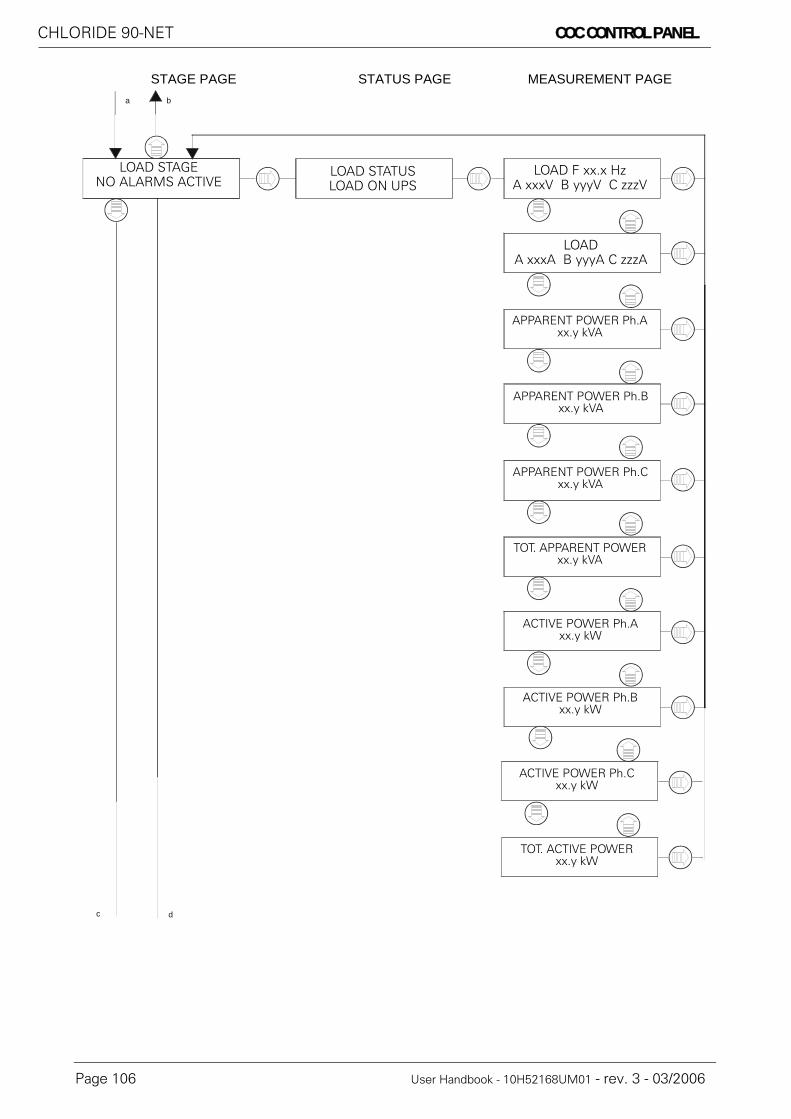
CHLORIDE 90-NET COC CONTROL PANEL
Page 106 User Handbook - 10H52168UM01 - rev. 3 - 03/2006
STAGE PAGE STATUS PAGE MEASUREMENT PAGEa b
dc
LOAD STATUSLOAD ON UPS
LOAD F xx.x HzA xxxV B yyyV C zzzV
LOAD A xxxA B yyyA C zzzA
APPARENT POWER Ph.Axx.y kVA
APPARENT POWER Ph.Bxx.y kVA
APPARENT POWER Ph.Cxx.y kVA
TOT. APPARENT POWERxx.y kVA
ACTIVE POWER Ph.Axx.y kW
ACTIVE POWER Ph.Bxx.y kW
ACTIVE POWER Ph.Cxx.y kW
TOT. ACTIVE POWERxx.y kW
LOAD STAGENO ALARMS ACTIVE

COC CONTROL PANEL CHLORIDE 90-NET
User Handbook - 10H52168UM01 - rev. 3 - 03/2006 Page 107
STAGE PAGE STATUS PAGE MEASUREMENT PAGEc d
m
e f g h i j
FUNCTION MENUPRESS > TO ACCESS
RESET STANDBY CMDPRESS > TO ACCESS
RESET FAULTPRESS > TO EXEC.
GUIDED PROCEDURESPRESS > TO ACCESS
LANGUAGE SELECTIONPRESS > TO ACCESS
SECT. GUIDEDPROCEDURES
ENGLISHPRESS > TO SELECT
FRANCAISPRESS > TO SELECT
DEUTSCHPRESS > TO SELECT
ITALIANOPRESS > TO SELECT
ESPANOLPRESS > TO SELECT
PORTUGUESPRESS > TO SELECT
LANGUAGE SELECTIONPRESS > TO EXIT
MANUAL COMMANDSPRESS > TO ACCESS
MANUALS COMMANDSPRESS > TO EXIT

CHLORIDE 90-NET COC CONTROL PANEL
Page 108 User Handbook - 10H52168UM01 - rev. 3 - 03/2006
STATUS PAGE MEASUREMENT PAGE
m e f g h i j
(1)
l
k
MANUAL CALLPRESS > TO EXEC
LIFE SERVICE MODEPRESS > TO SET
LIFE SERVICE MODEPRESS > TO RESET
DELAYED CALLPRESS > RESET
CONTROL BUTTONPRESS > TO ENABLE
CONTROL BUTTONPRESS > TO DISABLE
MANUAL COMMANDSPRESS > TO EXIT
I/O FUNCTIONPRESS > TO ACCESS
RESET I/O FUNCTIONPRESS > TO ACCESS
SET I/O FUNCTIONPRESS > TO ACCESS
I/O FUNCTIONPRESS > TO EXIT
OPTION PORT CONFIG.PRESS > TO ACCESS
SERIAL OPTIONNOT INSTALLED
FUNCTION MENUPRESS > TO EXIT
SERIAL OPTIONJBUS TERMINAL
SERIAL OPTIONTEST TERMINAL

COC CONTROL PANEL CHLORIDE 90-NET
User Handbook - 10H52168UM01 - rev. 3 - 03/2006 Page 109
STAGE PAGE STATUS PAGE MEASUREMENT PAGE
2) Only if JBUS option is selected.
l
k
(2)BAUD RATE
9600SELECT JBUSADDRESS 1
SAVE PARAMETERSNO
BAUD RATE300
BAUD RATE1200
BAUD RATE4800
BAUD RATE19200
SELECT JBUSADDRESS 2
SELECT JBUSADDRESS 255
SAVE PARAMETERSYES

CHLORIDE 90-NET COC CONTROL PANEL
Page 110 User Handbook - 10H52168UM01 - rev. 3 - 03/2006
11.4. Desription of COC system stages
STAGE STATUS ALARMS MEASUREMENTS
The following conditions may appear instead of “SYSTEM NORMAL”, on the "SYSTEM" (first) page:• SERVICE WARNING• SYSTEM FAULT• RES. TRANSF. STANDBY• UPS TRANSF. STANDBY• LIFE SERVICE MODE• COMMAND DISABLED• E.P.O. ACTIVE
Machine status and other information will be displayed on the "STATUS" (second) page:• UPS SIZE• NUMBER OF UPS• NOMINAL VOLTAGE• NOMINAL FREQUENCY• HIGH FAULT CLEARANCE ENEABLED• DIAL IN PROGRESS• DATA TRANSF. ACTIVE• SLAVE CONNECTION• ROUTINE CALL• MANUAL CALL• EMERGENCY CALL• LIFE BUFFER FULL• RESCHEDULED CALL• Rev. 1.x xx/xx/xx - Revision of display board software• Rev. 1.x xx/xx/xx - revision of CU4 software
COXC xxxkVASYSTEM NORMAL (see below)
SYSTEM ALARMS(see below)
(see below)

COC CONTROL PANEL CHLORIDE 90-NET
User Handbook - 10H52168UM01 - rev. 3 - 03/2006 Page 111
Any active alarms are displayed on the "ALARMS" (third) page. Each message is associated with one of thefollowing conditions:
The following measurements appear on the "MEASUREMENTS" (fourth) page:
• TIME OF NEXT CALL:YY-MM-DD hh:mm:ss
• DIAL DELAYED FORDD hh:mm:ss
• INLET AIRTemp: 37°C
• TOTAL MAINS FAILURESxxx• MAINS FAILURE TIME
TIME DD : hh : mm : ss• CALENDAR
YY-MM-DD hh:mm
MESSAGE CONDITION
GENERAL FAULT FAULT
CU4 EPROM CHECKSUM FAULT FAULT
CU4 EEPROM FAULT FAULT
COC SERVICE ACTIVE WARNING
VENTILATOR LIFE END WARNING
COMMISSIONING MODE WARNING
CU4 COMMUNICATION LOST WARNING
PARALLEL RES. FAULT FAULT
POB FAULT FAULT
IIC 1 EEPROM FAULT FAULT
IIC 2 EEPROM FAULT FAULT
IIC BUS ERROR WARNING
DISPLAY CMOSS FAULT FAULT
DISPLAY EEPROM FAULT FAULT
BYPASS SENS. FAULT FAULT
I/O CONFLICT WARNING
TEMPERATURE USER ALARM WARNING
TEMP. OUT OF RANGE WARNINGTEMP. OUT OF RANGE/FAULT WARNING
CONFIG. DATA LOST FAULT
CONTROL BUTTON ENABLED WARNING

CHLORIDE 90-NET COC CONTROL PANEL
Page 112 User Handbook - 10H52168UM01 - rev. 3 - 03/2006
11.5. COC RESERVE stage description
STAGE STATUS ALARMS MEASUREMENTS
The following conditions may appear instead of “NO ALARMS ACTIVE”, on the "RESERVE STAGE" (first)page:
• E.P.O. ACTIVE• FAULT• WARNING
Machine status and other information will be displayed on the "RESERVE STATUS" (second) page:• RESERVE VALID• RESERVE NOT VALID• CU4 COMMUNIC. LOST
Any active alarms are displayed on the "ALARMS" (third) page. Each message is associated with one of thefollowing conditions:
* Available only with certain revisions of CU4 and Display software.
The following condition may be displayed on the "MEASUREMENTS" (fourth) page.• RESERVE 50.0Hz
A 230V B 230V C 230V
MESSAGE CONDITION
RES. TRANSF. PROTECT FAULT
RESERVE BREAKER OPEN WARNING
BACKFEED PROT ACTIVE FAULT
OVERLOAD FAULT
PHASE 1 NOT OK FAULT
PHASE 2 NOT OK FAULT
PHASE 3 NOT OK FAULT
RESERVE SUPPLY FAULT FAULT
RESERVE HW FAULT FAULT
PHASE SEQUENCE ERROR WARNING
RESERVE NOT VALID WARNING
RESERVE FUSE BLOWN FAULT
RES. MAINTEN. BRK. OPEN* WARNING
ALARMS NOT AVAILABLE WARNING
STATIC SWITCH OVERTEMP FAULT
RESERVE STAGENO ALARMS ACTIVE
RESERVE STATUS(see below)
RESERVE ALARMS(see below)
(see below)

COC CONTROL PANEL CHLORIDE 90-NET
User Handbook - 10H52168UM01 - rev. 3 - 03/2006 Page 113
11.6. COC UPS stage description
STAGE STATUS ALARMS MEASUREMENTS
The following conditions may appear instead of “NO ALARMS ACTIVE”, on the "UPS STAGE" (first) page:• E.P.O. ACTIVE• WARNING
Machine status and other information will be displayed on the "UPS STATUS" (second) page:• UPS NORMAL• UPS A WARNING• UPS B WARNING• UPS C WARNING• UPS D WARNING• UPS E WARNING• UPS F WARNING• UPS G WARNING• UPS H WARNING• CU4 COMMUNIC. LOST
Any active alarms are displayed on the "ALARMS" (third) page. Each message is associated with one of thefollowing conditions:
The following conditions may be displayed on the "MEASUREMENTS" (fourth) page.• LOAD 50.0Hz
A 235V B 234V C 233V• LOAD 50.0Hz
A 20A B 23A C 33A• OVERLOAD THRESHOLD
xxx% (@yy°C)
MESSAGE CONDITION MESSAGE CONDITION
UPS A ALARM WARNING UPS E ALARM WARNING
UPS A SHUTDOWN IMM. WARNING UPS E SHUTDOWN IMM. WARNING
UPS A DISCONNECTED WARNING UPS E DISCONNECTED WARNING
UPS B ALARM WARNING UPS F ALARM WARNING
UPS B SHUTDOWN IMM. WARNING UPS F SHUTDOWN IMM. WARNING
UPS B DISCONNECTED WARNING UPS F DISCONNECTED WARNING
UPS C ALARM WARNING UPS G ALARM WARNING
UPS C SHUTDOWN IMM. WARNING UPS G SHUTDOWN IMM. WARNING
UPS C DISCONNECTED WARNING UPS G DISCONNECTED WARNING
UPS D ALARM WARNING UPS H ALARM WARNING
UPS D SHUTDOWN IMM. WARNING UPS H SHUTDOWN IMM. WARNING
UPS D DISCONNECTED WARNING UPS H DISCONNECTED WARNING
UPS STAGENO ALARMS ACTIVE
UPS STATUS(see below)
UPS ALARMS(see below)
(see below)

CHLORIDE 90-NET COC CONTROL PANEL
Page 114 User Handbook - 10H52168UM01 - rev. 3 - 03/2006
11.7. LOAD stage description
STAGE STATUS ALARMS MEASUREMENTS
The following conditions may appear instead of “NO ALARMS ACTIVE”, on the "LOAD STAGE" (first) page:• E.P.O. ACTIVE• FAULT• WARNING
Machine status and other information will be displayed on the "LOAD STATUS" (second) page:• LOAD ON RESERVE• LOAD ON UPS• LOAD ON BYPASS• LOAD NOT SUPPLIED• CU4 COMMUNIC. LOST
Any active alarms are displayed on the "ALARMS" (third) page. Each message is associated with one of thefollowing conditions:
The following condition may be displayed on the "MEASUREMENTS" (fourth) page.• OUTPUT 50.0Hz
A 230V B 230V C 230V• OUTPUT
A 20A B 23A C 33A• ACTIVE POWER Ph.A
A 123kW• ACTIVE POWER Ph.B
B 123kW• ACTIVE POWER Ph.C
C 123kW• TOTAL ACTIVE POWER
369kW• APPARENT POWER Ph.A
A 123kVA• APPARENT POWER Ph.B
B 123kVA• APPARENT POWER Ph.C
C 123kVA• TOTAL APPARENT POWER
369kVA
MESSAGE CONDITION
INSULATION FAILURE FAULT
OUTPUT SWITCH OPEN WARNING
OVERLOAD WARNING
LOAD TOO HIGH WARNING
BYPASS SWITCH CLOSED WARNING
ALARMS NOT AVAILABLE WARNING
OUTPUT VOLTS HIGH FAULT
OUTPUT VOLTS LOW FAULT
OUT. FREQ. ERROR FAULT
OUTPUT SHORT CIRC. FAULT
LOAD STAGENO ALARMS ACTIVE
LOAD STATUS(see below)
LOAD ALARMS(see below)
(see below)

OPERATING PROCEDURES CHLORIDE 90-NET
User Handbook - 10H52168UM01 - rev. 3 - 03/2006 Page 115
12. OPERATING PROCEDURESFor the following procedures, assume that the UPS is in one of the following operating modes:
• Switched off: all network and power switches are open. The load is voltage free.• Service bypass operation: the UPS is switched off, but the load is connected via the service bypass
switch supply line to the unprotected mains.• Normal operation: all relevant mains and power switches are connected. The load is supplied by the UPS.
To access the guided procedures select “Guided Procedures” from the display Main Menu (see Table 34 onpage 95). The procedures available for the current UPS configuration are displayed. The following table liststhe various procedures that can be carried out for each configuration:
NoticeRefer to para 10.1. on page 91.
NoticeThe acoustic alarm may be activated at various times in this procedure. It can be switched off by pressing the "Test/Reset" pushbutton.
NoticeWarning messages may appear briefly on the display. However, these may be dis-regarded.
Table 38: UPS GUIDED PROCEDURES
Single UPS Distributed Parallel(with SBS)a)
a) In parallel systems that include the System Bypass Switch (SBS), configure parameter P578 = 1 on the PPVis “Parallel and Ext. Synch. Configuration” page, and enable the SBS I/O functions (see “Function R for parallel UPS with SBS” on page 142).
Centralised Parallel
COCb)
b) In the case of Centralised Parallel systems, the COC is equipped with a non-graphical LCD, therefore only the UPS procedures have been implemented. The COC proce-dures are described in “CENTRALISED parallel system” on page 120.
Manual Bypass Manual Bypass Manual Bypass
Return from Bypass Return from Bypass Return from Bypass
Start Up System Start Up Start Up
Shutdown System Shut Down Shutdown
UPS
UPS Start Up
UPS Shut Down

CHLORIDE 90-NET OPERATING PROCEDURES
Page 116 User Handbook - 10H52168UM01 - rev. 3 - 03/2006
12.1. Sample guided procedure - Manual Bypass
When the desired procedure has been selected from the Guided Procedures menu (in this case the SingleUPS Manual Bypass procedure), the following window appears in the display, illustrating the principle UPScomponents and their current status:
The various UPS switches are also represented - the Maintenance Bypass switch, QS3, is shown in the open(OFF) position in the above example - these show the current status of the switches, and flash to indicatethe user must open, or close, the corresponding switch.
In the event of a fault, a warning message is displayed (see “Warning messages” on page 119 for full list ofwarning messages), exit the procedure, correct the fault condition and reset before proceeding.Pressing the button identified by the “Exit” message at any moment interrupts the procedure.
In this case, the message “Stop Inverter” appears in the bottom right of the display, and the Stop sym-bol flashes over the Inverter, indicating that the user must stop the Inverter by pressing the correspondingbutton on the “Control Panel” on page 93. (See “Instruction messages” on page 119 for full list of instructionmessages).
PROCEDURE:
(1) Press the Stop Inverter button for at least 2 seconds.(2) The messge “Wait load on Res.” is displayed, indicating that the system is waiting for the load to be transferred to the Reserve supply.
NoticeThe BY-PASS switch handle is delivered separately, and must be fitted prior to commencing MANUAL BYPASS procedure and removed when completed.
ExitStopInverter
Manual Bypass
Exit Wait load on Res
Manual Bypass

OPERATING PROCEDURES CHLORIDE 90-NET
User Handbook - 10H52168UM01 - rev. 3 - 03/2006 Page 117
(3) The message “Close QS3” is displayed, and the symbol representing QS3 on the display begins to flash.
Close QS3 (Maintenance Bypass switch)(4) The message “Open QS4” is displayed, and the symbol representing QS4 on the display begins to flash.
Open QS4 (Output switch).(5) The message “Open QS2” is displayed, and the symbol representing QS2 on the display begins to flash.
Open QS2 (Bypass switch)
Exit Close QS3
Manual BypassQS3
Exit Open QS4
Manual Bypass
QS4
Exit Open QS2
Manual Bypass
QS2

CHLORIDE 90-NET OPERATING PROCEDURES
Page 118 User Handbook - 10H52168UM01 - rev. 3 - 03/2006
(6) The message “Open QS9” is displayed, and the symbol representing QS9 on the display begins to flash.
Open QS9 (Battery switch)(7) The message “Open QS1” is displayed, and the symbol representing QS1 on the display begins to flash.
Open QS1 (Input switch).(8) The message “End of procedure” is displayed.
Exit Open QS9
Manual Bypass
QS9
Exit Open QS1
Manual Bypass
QS1
Exit End of procedure
Manual Bypass

OPERATING PROCEDURES CHLORIDE 90-NET
User Handbook - 10H52168UM01 - rev. 3 - 03/2006 Page 119
12.1.1. Instruction messages
12.1.2. Warning messages
Stop Inverter Open QS1 Close QS1
Start Inverter Open QS2 Close QS2
Press Exit Open QS3 Close QS3
Reset Fault Open QS4 Close QS4
Open QS5 Close QS5
Open QS6 Close QS6
Open QS9 Close QS9
Procedure not OK
Wait Vdc in range
Waiting Bypass ON
Wait Load on Bypass
Wait Load on Invert.

CHLORIDE 90-NET OPERATING PROCEDURES
Page 120 User Handbook - 10H52168UM01 - rev. 3 - 03/2006
12.2. CENTRALISED parallel system
The system can be configured as either centralised parallel (1) or centralised parallel with high fault clearancemode (2); the correct parameter settings for these configurations are:
(1) PNU 568 = 0 on both UPS and COC; PNU 73 = 2 on UPS and PNU 73 = 1 on COC(2) PNU 568 = 0 on both UPS and COC; PNU 73 = 3 on UPS and PNU 73 = 1 on COC
• MANUAL BYPASS• RETURN FROM BYPASS (*)• START UP (*)• SHUTDOWN
(*) Control logic is not supplied when the UPS is stopped or in by-pass. To follow the guided procedure, eitherthe primary input switch or the reserve input switch must be closed.If the requested procedure is incompatible with the machine status, the procedure will not be accessed andthe following message will appear:
"PROCEDURE NOT OK"
The microprocessor makes sure that each procedure is performed correctly, giving step-by-step instructionsto the operator for the manual operations required.When an operation has been executed or a required condition has been verified, the message relating to thenext step is displayed until the procedure has been completed.If a required operation is not executed or a condition is not verified, a message will be displayed showing thestatus that temporarily or permanently prevents the procedure from being completed.
If the procedure has been successfully completed, the following message will be displayed.
“PROCEDURE COMPLETE”
The maximum number of messages that can be displayed is listed on the following pages.Each message may contain an operation request or an indication. Each message is flanked by the type ofmessage (operation or indication) and the description.
Symbols
NoticeTHESE PROCEDURES ARE DISPLAYED ON THE C.O.C. NON-GRAPHICAL DISPLAY
From the COC “GUIDED PROCEDURE” page, press to access the 4 procedures below:
Press to exit the procedure at any time
NoticeIf the current procedure cannot be completed due to permanent alarms or blocking conditions, the operator (depending on level of personal training) must:
• call Back-up assistance;or
• follow the instructions given in the "Troubleshooting" section of the Technical Manual
MANUAL BYPASSPRESS > TO ACCESS
= example of display message
= example of control panel pushbutton

OPERATING PROCEDURES CHLORIDE 90-NET
User Handbook - 10H52168UM01 - rev. 3 - 03/2006 Page 121
12.2.1. Procedure selectionThe following messages relate to the 4 COC procedures available for selection. The pushbuttons to accessand scroll each procedure on the COC Control Panel are also illustrated.
Press to access a procedure; if the machine status permits the operation, the first messagewill be displayed.
Once the procedure has been completed, press to return to the “GUIDED PROCEDURE”
page. The diagram below represents the “MANUAL BYPASS” procedure.
GUIDED PROCEDURESPRESS > TO ACCESS
MANUAL BYPASSPRESS > TO ACCESS
MANUAL BYPASSCLOSE SWITCH QS2
RETURN FROM BYPASSPRESS > TO ACCESS
START UPPRESS > TO ACCESS
MANUAL BYPASSPROCEDURE COMPLETE
SHUT DOWNPRESS > TO ACCESS
GUIDED PROCEDURESPRESS > TO EXIT

CHLORIDE 90-NET OPERATING PROCEDURES
Page 122 User Handbook - 10H52168UM01 - rev. 3 - 03/2006
Press to access a procedure; if the machine status does not permit the operation, the mes-sage “PROCEDURE NOT OK” appears in the machine status message.
Press once again to move on to the next procedure. The diagram below illustrates a manualbypass request when the UPS is already in the bypass condition.
GUIDED PROCEDURESPRESS > TO ACCESS
MANUAL BYPASSPRESS > TO ACCESS
PROCEDURE NOT OKBYPASS SWITCH CLOSED
RETURN FROM BYPASSPRESS > TO ACCESS
START UPPRESS > TO ACCESS
SHUT DOWNPRESS > TO ACCESS
GUIDED PROCEDURESPRESS > TO EXIT

OPERATING PROCEDURES CHLORIDE 90-NET
User Handbook - 10H52168UM01 - rev. 3 - 03/2006 Page 123
12.2.2. System procedures (COC)12.2.2.1. System START UP procedure
MESSAGE NAME MESSAGE TYPE INFO
START UPRESET FAULT
Request for intervention System FAULT, reset before proceeding
START UPEPO ACTIVE
Indication Procedure not possible while EPO is active
START UPOPEN QS3 SWITCH
Request for intervention Open Bypass switch QS3
START UPCLOSE QS2 SWITCH
Request for intervention Close Reseve switch QS2
START UPCLOSE QS4 SWITCH
Request for intervention Close output switch QS4
START UP ON UPSTHEN PRESS BUZZER
Request for intervention Perform parallel UPS start up procedure and
press to proceed
START UPWAIT LOAD ON RESERVE
Indication System is awaiting load on Reserve
START UPTRANSFER LOAD TO UPS
Request for interventionTransfer load to Inverter by pressing
CHECK UPS FAULTTHEN PRESS BUZZER
Request for intervention Check if any FAULTS are active on the UPS, then
press to proceed
START UPWAIT LOAD ON INV.
Indication The system is awaiting load on Inverter
START UPPROCEDURE COMPLETE
Request for interventionPress to exit.
R I

CHLORIDE 90-NET OPERATING PROCEDURES
Page 124 User Handbook - 10H52168UM01 - rev. 3 - 03/2006
12.2.2.2. System SHUT DOWN procedure
MESSAGE NAME MESSAGE TYPE INFO
SHUT DOWNRESET FAULT
Request for intervention System FAULT, reset before proceeding
SHUT DOWNEPO ACTIVE
Indication Procedure not possible while EPO is active
SHUT DOWNOPEN QS3 SWITCH
Request for intervention Open Bypass switch QS3
SHUT DOWNTRANSFER LOAD TO RES
Request for interventionTransfer load to Res. by pressing
SHUT DOWNWAIT LOAD ON RESERVE
Indication System is awaiting load on Reserve
SHUT DOWN ON UPSTHEN PRESS BUZZER
Request for intervention Perform parallel UPS shutdown procedure and
press to proceed
SHUT DOWNOPEN QS4 SWITCH
Request for intervention Open output switch QS4
SHUT DOWNOPEN QS2 SWITCH
Request for intervention Open Reserve switch QS2
SHUT DOWNPROCEDURE COMPLETE
Request for interventionPress to exit.
R I

OPERATING PROCEDURES CHLORIDE 90-NET
User Handbook - 10H52168UM01 - rev. 3 - 03/2006 Page 125
12.2.2.3. System MANUAL BYPASS procedure
MESSAGE NAME MESSAGE TYPE INFO
MANUAL BYPASSRESET FAULT
Request for intervention System FAULT, reset before proceeding
MANUAL BYPASSEPO ACTIVE
Indication Procedure not possible while EPO is active
MANUAL BYPASSWAIT RESERVE OK
Indication System awaiting Reserve OK
MANUAL BYPASSTRANSFER LOAD TO
RESERVE
Request for interventionTransfer load to Reserve by pressing
MANUAL BYPASSWAIT LOAD ON RESERVE
Indication System awaiting load on Reserve
MANUAL BYPASSCLOSE QS3 SWITCH
Request for intervention Close Bypass switch QS3
SHUT DOWN ON UPSTHEN PRESS BUZZER
Request for intervention Perform parallel UPS shutdown procedure and
press to proceed
MANUAL BYPASSOPEN QS4 SWITCH
Request for intervention Open Reserve switch QS4
MANUAL BYPASSOPEN QS2 SWITCH
Request for intervention Open Output switch QS2
MANUAL BYPASSPROCEDURE COMPLETE
Request for interventionPress to exit.
R I

CHLORIDE 90-NET OPERATING PROCEDURES
Page 126 User Handbook - 10H52168UM01 - rev. 3 - 03/2006
12.2.2.4. System RETURN FROM BYPASS procedure
MESSAGE NAME MESSAGE TYPE INFO
RETURN FROM BYPASSRESET FAULT
Request for intervention System FAULT, reset before proceeding
RETURN FROM BYPASSEPO ACTIVE
Indication Procedure not possible while EPO is active
RETURN FROM BYPASSCLOSE QS2 SWITCH
Request for intervention Close Output switch QS2
RETURN FROM BYPASSCLOSE QS4 SWITCH
Request for intervention Close Output switch QS4
START UP ON UPSTHEN PRESS BUZZER
Request for intervention Perform parallel UPS start up procedure and
press to proceed
RETURN FROM BYPASSWAIT LOAD ON RESERVE
Indication System is awaiting load on Reserve
RETURN FROM BYPASSOPEN QS3 SWITCH
Request for intervention Open Bypass switch QS3
RETURN FROM BYPASSTRANSFER LOAD TO UPS
Request for interventionTransfer load to Inverter by pressing
CHECK UPS FAULTTHEN PRESS BUZZER
Request for intervention Check if any FAULTS are active on the UPS, then
press to proceed
RETURN FROM BYPASSWAIT LOAD ON UPS
Indication System is awaiting load on Inverter
RETURN FROM BYPASSPROCEDURE COMPLETE
Request for interventionPress to exit.
R I

OPERATING PROCEDURES CHLORIDE 90-NET
User Handbook - 10H52168UM01 - rev. 3 - 03/2006 Page 127
12.3. Parallel operation
12.3.1. System configurationFigure 55 - Connections for modular parallel system
Switching to ONLINE operation:
Switch ON the Inverters of all the UPS, one after the other, by pressing and holding the controlpanel Inverter Start button for 2 seconds.
Once they are all switched ON, the inverters of the UPS units synchronise and take over the load. TheUPS is now in ONLINE operation.
Switching from ONLINE to BYPASS operation:
Switch OFF the Inverters of all the UPS, one after the other, by pressing and holding the controlpanel Inverter Stop button for 2 seconds (see para 9.3.3. on page 66).
Once they are all switched to OFF, all inverters switch off and all bypasses switch on.
WarningThe external service bypass may only be connected in bypass operation. Doing so during ONLINE operationmay damage UPS and connected loads.
QS4
QS9
QS3
QS1QS2
QS6
QS4
QS5
QS9
QS2QS1
QS3
Mains supply Reserve supply Mains supply Reserve supply
UPS1 UPS2 UPSn
Bypassdisconnector(Option S.B.S.)
N.B. When using the S.B.S. option, the switches QS3 of the UPSare not used (leave in Open position)
N.B. With modular parallel systems comprising more than 2 UPS,the System Bypass Switch (S.B.S.) must be installed.

CHLORIDE 90-NET OPERATING PROCEDURES
Page 128 User Handbook - 10H52168UM01 - rev. 3 - 03/2006
12.4. Guided procedure
12.4.1. Initial start up - with SBS
Step 1:The Load is supplied via the external manual Bypass (SBS) QS5
• Close bypass switch QS3 on each Unit• Close system output switch (SBS) QS6
NoticeTHE S.B.S. PROCEDURES MAKE REFERENCE TO THE SWITCHES QS5 AND QS6; THESE SWITCHES ARE LOCATED ON THE S.B.S., AND NOT ON THE IN-DIVIDUAL UPS, THEREFORE THEIR POSITION AND STATUS ARE NOT INDI-CATED ON THE UPS DISPLAY
QS4
QS1
QS3QS2
QS1
QS3QS2
QS4
QS9 QS9
QS5
QS6
POB POB
QS3
QS4
QS1
QS2
QS1
QS2
QS4
QS9 QS9
QS5
QS6
QS3
POB POB

OPERATING PROCEDURES CHLORIDE 90-NET
User Handbook - 10H52168UM01 - rev. 3 - 03/2006 Page 129
Step 2:On each UPS:
• Close Reserve switch QS2• Close Input switch QS1• Output switch QS4
The Load is still supplied via the manual Bypass, while the rectifiers and Reserve supplies of the individualUPS are connected to their corresponding supply lines.
Step 3:Check that the battery-charger voltages on the UPS side of the battery breakers are the same polarityas the those on the battery side of the breakers.When the bypasses are ready the messages "LOAD ON BYPASS" and "BATTERY BREAKER OPEN" are dis-played.
• Close each UPS battery isolating switch QS9• Message "BATTERY BREAKER OPEN" is cancelled• Open system by-pass switch (SBS) QS5• Open each UPS Bypass switch QS3• Message "LOAD ON BYPASS" is cancelled
The load now receives its supply via the UPS Static switches.
QS4
QS1 QS3QS2
QS1QS3QS2
QS4
QS9 QS9
QS5
QS6
POB POB
QS4
QS1QS3
QS2
QS1QS3
QS2
QS4
QS9 QS9
QS5
QS6
POB POB

CHLORIDE 90-NET OPERATING PROCEDURES
Page 130 User Handbook - 10H52168UM01 - rev. 3 - 03/2006
Step 4:One at a time, press and hold for at least two seconds the Inverter Start buttons on the control panel (seepara 9.1. on page 63) of each UPS. Once the last Inverter has been started they will all go on line ("LOAD ONINVERTER") and the Load will be supplied by the UPS Inverters.
QS4
QS1
QS3 QS2
QS1
QS3 QS2
QS4
QS9 QS9
QS5
QS6
POB POB

OPERATING PROCEDURES CHLORIDE 90-NET
User Handbook - 10H52168UM01 - rev. 3 - 03/2006 Page 131
12.4.2. Uncoupling an individual UPS from a parallel systemThe procedure for uncoupling an uninterruptible power supply from the configuration (for maintenance pur-poses, for example) is described below. In this example UPS No. B is decoupled, leaving No. A to supply theload.N.B. This procedure is valid for redundant parallel systems consisting of up to 2 UPS only; for more informa-tion contact CHLORIDE Technical Support.
Step 1:• Open output switch QS4 of UPS B
The message "OUTPUT SWITCH OPEN" is displayed.
Step 2:• Open UPS B Reserve switch QS2• Open UPS B battery isolating switch QS9• Open UPS B Input switch QS1
QS4
QS1
QS3 QS2
QS1
QS3 QS2
QS4
QS9 QS9
QS5
QS6
POB POB
QS4
QS1QS3
QS2
QS1QS3QS2
QS4
QS9 QS9
QS5
QS6
POB POB

CHLORIDE 90-NET OPERATING PROCEDURES
Page 132 User Handbook - 10H52168UM01 - rev. 3 - 03/2006

I/O FUNCTIONS CHLORIDE 90-NET
User Handbook - 10H52168UM01 - rev. 3 - 03/2006 Page 133
13. I/O FUNCTIONSThe UPS in the 90-NET series are equipped with a program capable of managing a certain number of factory-installed input/output functions, which allow the User to adapt the UPS to his own needs, taking advantageof the input or output contacts available on the UPS terminal board. For some of these a message is displayedon the LCD. The following is a description of each function together with the number of Input/Outputs used.A series of Input and Output functions can also configured at the interfaces X7 and X8, using PPVis (see para13.7. on page 146).
13.1. List of Individual functions for single and modular parallel UPS
NoticeEach function is identified by a letter (A, B etc.) This is necessary since the functions are identified by these letters on the UPS Display.
Function name Description Inputsused
Outputsused
A Common vented(wet) batteries.
The controls for battery tests or rapid charging are transmitted orreceived through three input and three output contacts for UPS thathave batteries in common.
2 2
B Common VRLA(sealed) batteries.
The controls for battery tests are transmitted and received throughtwo input and two output contacts for UPS that have batteries incommon.
1 1
C Harmonic Filter Open This function should be enabled when the Input Filter is fitted, it pro-vides the “HARMONIC FILTER OPEN” alarm message at the recti-fier stage.
1 0
D Not Used
E Fan (ON-OFF) in bat-tery compartment
A contact is activated to control a fan in the battery compartment,which operates as follows:1) It turns on when a set temperature threshold is exceeded (default40°C) and will remain on for a set minimum time (default 1 hour).2) For batteries with rapid charging function, the contact is activatedduring this process and will be kept on for an adjustable additionalminimum time (default 1 hour).
0 1
F Battery fuse monitor When the input is active, the message “BATTERY FUSE BLOWN”will appear on the battery alarm page.
1 0
G Battery compart-ment overheated
A contact is activated when a temperature threshold set by the cus-tomer is exceeded. The default setting is 40°C.
0 1
H Battery temperatureoutside tolerance
A contact is activated when the temperature is outside normal oper-ating limits (0°-40°C)
0 1
I Battery earth faultoutput
When this alarm is activated, with the rectifier off or with a UPSincluded in an isolated system, the message “INSULATION FAIL-URE” appears on the battery alarm page and an output contact isactivated.
1 1
J EPO Input When this alarm is activated the rectifier and inverter are switchedoff and both reserve and inverter static switches are OPEN – themessage “EPO ACTIVE” is displayed in any page. In this conditionthe load is no longer supplied and the UPS control boards are sup-plied by the battery.
1 0
K EPO Output This function copies the EPO Input status onto an output, which canthan be used to open an circuit breaker downstream of the UPS toisolate the load.
0 1
L Input earth fault When this input is activated the message “INSULATION FAILURE”appears on the rectifier alarm page.
1 0
M UPS service active Detects when the UPS front panel is open. When this input is acti-vated, the message “ UPS SERVICE ACTIVE” also appears on thesystem alarm page.
1 0

CHLORIDE 90-NET I/O FUNCTIONS
Page 134 User Handbook - 10H52168UM01 - rev. 3 - 03/2006
O Output earth fault When this input is activated the message “INSULATION FAILURE”appears on the load alarm page.
1 0
P Reserve input trans-former protection
When this input is activated the message “RES. TRANSF. PRO-TECT” appears on the reserve alarm page.
1 0
Q Primary input trans-former protection
When this input is activated the message “MAINS TRANSF. PRO-TECT” appears on the rectifier alarm page.
1 0
R SBS Output switchopen
In systems with optional SBS, this function detects the status of theSystem Output switch. The message “SYSTEM OUTPUT SWOPEN” is displayed on the load alarm page.
1 0
S Insufficient Ventila-tion
When this input is activated the message “INSUFF. VENTILATION”appears on the system alarm page.
1 0
T Load on Reserve Active when the load is supplied from the Reserve 0 1
V Extern Synchronisa-tion system fault
An output contact is activated when an external synchronisation sys-tem fault is present. The message “SYNCHRONIZAT. FAULT” is dis-played on the system alarm page.
0 1
X Backfeed Protection When this input is activated, the message “BACKFEED PROTEC-TION ACTIVE” appears on the reserve alarm page.
1 1
Y External Battery This input controls the external battery breaker when the externalbattery option is installed. The external breaker modifies the overallbattery breaker status in the internal logic.
1 0
Z Hydrogen present When this alarm is active the battery charger is inhibited and themessage “BATT. CHARGE INHIBIT” is displayed in the battery alarmpage.
1 0
AA Inverter Overload This output is active with inverter running, each time the loadexceeds the overload threshold defined by the inlet air temperature
0 1
AB Load on Inverter This output is active when the load is on the conditioned line 0 1
AC Inverter synchro-nised
This output is active when the inverter is synchronised with thereserve line and there is no delay when switching to the direct line
0 1
AD Rectifier running This output is active when the rectifier is on (charger on input highfrom the rectifier controller board)
0 1
AE Summary alarm This output is active when there is an active alarm in the system(WARNING or FAULT)
0 1
AF Shutdown imminent This output is active when thre is an imminent shutdown warningactive on the CU4 (WARNING 10)
0 1
AG Battery charging This output is activewhen the battery charging current is greaterthan the parameter PNU 626-i03 for more than 10s.
0 1
AH Recifier fault This output is active each time there is a fault on the rectifier 0 1
AI Inverter fault This output is active each time there is a fault on the inverter 0 1
AJ Inverter
over-temperatreThis output is active when the inverter overtemperature threshold isreached (CU FAULT 33)
0 1
AK Battery discharging This output is active when the battery is not charging and its voltagefalls below the parameter PNU 625-i06
0 1
AL Battery fault This output is active when there is a battery fault active 0 1
AM Mains failure This output is active each time a primary supply fault occurs 0 1
AN Service bypass This output is active when the service or system bypass switchesare closed
0 1
AO Inverter off This output is active when the inverter is off.“Inverter off” is a specific state, and does not include Inverter fault:when there is an inverter fault, the inverter is switched off, but theindicated state is “Inverter fault” and not “Inverter off”
0 1
AP Battery disconnected This output is active when the battery switch is open 0 1
AQ Reserve fault This output is active when there is a fault on the reserve line 0 1
AR Generic input/output This output is active when the input is active 1 1

I/O FUNCTIONS CHLORIDE 90-NET
User Handbook - 10H52168UM01 - rev. 3 - 03/2006 Page 135
13.2. List of individual COC functionsFunction name Description Number of
inputsused
Numberof out-puts used
A E.P.O. Input When the EPO input is active the local Reserve Static is opened. TheEPO message appears in all stage windows.
1 0
B E.P.O. Output When the EPO output is present and outout contact is activated,which drives an external relay, downstram of the Output
0 1
C Output earth fault When this input is activated the message “INSULATION FAILURE”appears on the load alarm page.
1 0
D Reserve inputtransformer pro-tection
When this input is activated the message “RES. TRANSF. PRO-TECT” appears on the reserve alarm page.
1 0
E COC serviceactive
When this input is activated the message “COC SERVICE ACTIVE”appears in the system alarms page, if the unit front panel is open
1 0
F Heatsink overtemperature
If this function is enabled, an output contact is activiated when theheatsink over temperature sensor is active.
0 1
G Reserve Fuse
Blown
Active only on 1600/3200/4000A ratingsWhen this input is activated, the message “RESERVE FUSEBLOWN” appears on the reserve alarm page, and the reserve line isdisabled
1 0
H Load on Reserve This function, which is enabled as a default setting, sets the relatedoutput to 1 when the Load is supplied from the Reserve
0 1
I Load on UPS This function sets the related output to 1 when the Load is suppliedfrom the UPS Inverter.
0 1
J Inhibit LocalRetransfer Com-mand
The COC transfers the Load to the Reserve by means of an input con-tact. While this command is enabled, the transfer push-button is disa-bled, thus inhibiting load transfer.
1 0
K Backfeed Protec-tion
When this input is activated, the message “BACKFEED PROT.ACTIVE” appears in the Reserve alarm page, and an output is acti-vated
1 1
L Reserve notavailable
A output contact is activated when the Reserve supply is outside tol-erance or unavailable (see Reserve Warning and Fault)
0 1
M MaintenanceBypass enabled
A contact is activated when the static switch is on Reserve and theReserve switch is closed. This function is used to enable the opera-tion of an external bypass circuit breaker.
0 1
N Reserve Mainte-nance BreakerOpen
Opens the Reserve Maintenance Breaker so that the Reserve supplyis not available, even if within tolerance. The load transfer push-but-ton is disabled and the message “RES. MAINTEN. BRK. OPEN”appears in the Reserve stage.
1 0

CHLORIDE 90-NET I/O FUNCTIONS
Page 136 User Handbook - 10H52168UM01 - rev. 3 - 03/2006
13.3. I/O Function setting via PC terminal
The I/O Function configuration, originally managed through the old LCD, can now be effected also throughthe Terminal PC connected to the display board using the optional RS232 board (P/N. 15B10808G1).This generates a new page on the terminal that will be used as an interface to enable the I/O function. Thisinterface has to be linked to the I/O Function manager, that, depending on the I/O board number allocated,maps the functions on the available physical I/O.In order to preserve compatibility with the existing 90NET units, it will be possible to configure the I/O func-tion also through the old LCD.I/O Setup through PC Terminal interface is very similar to the I/O Setup with old 90Net LCD.From the Terminal main page chose F6 - Setup I/O Functions:
The following page will be:
The messages have the same meaning as in the old LCD.

I/O FUNCTIONS CHLORIDE 90-NET
User Handbook - 10H52168UM01 - rev. 3 - 03/2006 Page 137
Choosing Reset I/O function you'll be asked for a confirmation:
Press "Y" to confirm and "N" to abort.Choosing Set I/O function, the following page will be shown:
The functions can be configured as on the old LCD, remembering that "UP arrow", "DOWN arrow" and "RIGHTarrow" present in the old mimic panel, have been substituted with "U" key, "D" key and "R" key.

CHLORIDE 90-NET I/O FUNCTIONS
Page 138 User Handbook - 10H52168UM01 - rev. 3 - 03/2006
Going down through the functions till the latter, at the end a confirmation is requested to make the changeseffective:

I/O FUNCTIONS CHLORIDE 90-NET
User Handbook - 10H52168UM01 - rev. 3 - 03/2006 Page 139
Terminal assignments for individual or parallel UPS - XT1
COC terminal assignments - XT1
I/O CODE Number of terminal board contact
Supply Notes
User Input 1 9-10 standard Factory default setting:
Backfeed Protection input
User Input 2 13-14 standard
User Input 3 19-20 standard
User Input 4 15-16 standard
User Input 5 17-18 standard Factory default setting: E.P.O.
User Input 6 36-37 optional
Available only when optional 2nd I/O board is installed
User Input 7 40-41 optional
User Input 8 38-39 optional
User Input 9 42-43 optional
User Output 1 3-4-5 standard Factory default setting:
Backfeed Protection output
User Output 2 6-7-8 standard
Aux. Bypass Contacts 11-12 standard 600/800 kVA ratings only
User Output 3 30-31-32 optional
Available only when optional 2nd I/O board is installed
User Output 4 33-34-35 optional
MBSM contacts 100-200 optional
I/O CODE Number of terminal board contact
Supply Notes
User Input 1 9-10 standard Factory default setting:
Backfeed Protection input
User Input 2 13-14 standard
User Input 3 11-12 standard
User Input 4 15-16 standard
User Input 5 1-2 standard
User Input 6 36-37 (*) optional
Available only when optional 2nd I/O board is installed
User Input 7 40-41 (*) optional
User Input 8 38-39 (*) optional
User Input 9 42-43 (*) optional
User Output 1 3-4-5 standard Factory default setting:
Load on Bypass
User Output 2 6-7-8 standard Factory default setting:
Backfeed Protection output
User Output 3 30-31-32 (*) optional Available only when optional 2nd I/O board is installedUser Output 4 33-34-35 (*) optional

CHLORIDE 90-NET I/O FUNCTIONS
Page 140 User Handbook - 10H52168UM01 - rev. 3 - 03/2006
13.4. Description of function wiring with fixed terminal assignmentsThe input or output signals of some functions are automatically assigned to the terminals so as to alwaysfollow the same wiring pattern.Function A for individual and Parallel UPSThis function is essential when using UPS with vented (wet ) common batteries.
Wire the UPS together according to the following diagram:
NoticeWith this option it is also necessary to set the parameter via PPVIS - Rectifier Setting 630, 105 Parallel Charger Mode = 1.
45689101314
45689101314
45689101314
Enable function A as follows:Input 1 NEGATIVE polarityInput 2 NEGATIVE polarityOutput1 POSITIVE polarityOutput2 NEGATIVE polarity
UPS A
UPS B
UPS n

I/O FUNCTIONS CHLORIDE 90-NET
User Handbook - 10H52168UM01 - rev. 3 - 03/2006 Page 141
Function B for individual and Parallel UPSThis function is essential when using UPS with VRLA ( sealed ) common batteries.
Wire the UPS together according to the following diagram:
NoticeWith this option it is also necessary to set the parameter via PPVIS - Rectifier Setting 630, 105 Parallel Charger Mode = 1.
45689101314
45689101314
45689101314
Enable function B as follows:Input 1 NEGATIVE polarityInput 2 POSITIVE polarity
UPS A
UPS B
UPS n

CHLORIDE 90-NET I/O FUNCTIONS
Page 142 User Handbook - 10H52168UM01 - rev. 3 - 03/2006
Function J for individual and Parallel UPSTo activate the E.P.O. option, programme funtion J as illustrated below:
Function R for parallel UPS with SBSProgramme Function R - SBS Output - as follows:
13.5. Electrical specifications of input/output signals
The output terminals are voltage-free; max. rating:• 4 A/250 V AC,• 4 A/30 V DC
Contact resistance = 100 mohm.
The Input terminals need simply to be connected to voltage-free contacts.
If the input comes from a relay, the minimum contact current of the latter must be 15 mAmp.
XT11718
Enable function J as follows:Input 5 POSITIVE polarity
1516
X812
1516
X812
XT1
XT1
1516
X812
XT1
12345678
SBS System Bypass Switch
System Output Switch
Input 5: POSITIVE polarity
Program PPvis:• FUNTION INPUT (PNU 93) = 4• Manual Bypass Switch Report
INVERT (PNU 94) = 1

I/O FUNCTIONS CHLORIDE 90-NET
User Handbook - 10H52168UM01 - rev. 3 - 03/2006 Page 143
13.6. Table of functions
Below is a table of the functions activated on the individual or parallel UPS.These tables are given when necessary in the inspection report that accompanies each UPS.The options must be activated in sequence (i.e., if the options to be activated are G-C-I, activate option C,then option G, and finally option I).The user inputs and user outputs are assigned to the terminal board using the first free terminal on the left-hand side of the table.The INPUT polarities must be assigned keeping in mind the type of contact available to the customer andhow it is recognized by the UPS software.
The following table illustrates how to set the polarity of an Input:
The OUTPUT polarities must be assigned keeping in mind what condition it is given by the UPS software andwhat type of SECURITY the customer desires.
The following table illustrates how to set the polarity of an Input:
INPUT STATE POLARITY Software CONDITION Type of CONTACT
CLOSED POSITIVE OFF Normally Closed (NC)
OPEN POSITIVE ON Normally Closed (NC)
CLOSED NEGATIVE ON Normally Open (NO)
OPEN NEGATIVE OFF Normally Open (NO)
Software CONDITION POLARITY RELAY STATE SAFETY TYPE
ON (Alarm active) POSITIVE ON NEGATIVE
OFF (No alarm) POSITIVE OFF
ON (Alarm active) NEGATIVE OFF POSITIVE
OFF (No alarm) NEGATIVE ON

CHLORIDE 90-NET I/O FUNCTIONS
Page 144 User Handbook - 10H52168UM01 - rev. 3 - 03/2006
13.6.1. Table of functions activated on individual or parallel UPS
N = Negative PolarityP = Positive Polarity
NoticeThe functions on a grey background indicate options with fixed terminal assignment as de-scribed previously.
12
34
56
78
91
23
4
XT1
910
13
14
19
20
15
16
17
18
36
37
40
41
38
39
42
43
XT1
3 4
5
6 7
8
30 3
1 3
23
3 3
4 3
5
AN
PN
PN
PN
PN
PN
PN
PN
PN
PA
NP
NP
NP
NP
BN
PN
PN
PN
PN
PN
PN
PN
PN
PB
NP
NP
NP
NP
CN
PN
PN
PN
PN
PN
PN
PN
PN
PC
NP
NP
NP
NP
DN
PN
PN
PN
PN
PN
PN
PN
PN
PD
NP
NP
NP
NP
EN
PN
PN
PN
PN
PN
PN
PN
PN
PE
NP
NP
NP
NP
FN
PN
PN
PN
PN
PN
PN
PN
PN
PF
NP
NP
NP
NP
GN
PN
PN
PN
PN
PN
PN
PN
PN
PG
NP
NP
NP
NP
HN
PN
PN
PN
PN
PN
PN
PN
PN
PH
NP
NP
NP
NP
IN
PN
PN
PN
PN
PN
PN
PN
PN
PI
NP
NP
NP
NP
JN
PN
PN
PN
PN
PN
PN
PN
PN
PJ
NP
NP
NP
NP
KN
PN
PN
PN
PN
PN
PN
PN
PN
PK
NP
NP
NP
NP
LN
PN
PN
PN
PN
PN
PN
PN
PN
PL
NP
NP
NP
NP
MN
PN
PN
PN
PN
PN
PN
PN
PN
PM
NP
NP
NP
NP
NN
PN
PN
PN
PN
PN
PN
PN
PN
PN
NP
NP
NP
NP
ON
PN
PN
PN
PN
PN
PN
PN
PN
PO
NP
NP
NP
NP
PN
PN
PN
PN
PN
PN
PN
PN
PN
PP
NP
NP
NP
NP
QN
PN
PN
PN
PN
PN
PN
PN
PN
PQ
NP
NP
NP
NP
RN
PN
PN
PN
PN
PN
PN
PN
PN
PR
NP
NP
NP
NP
SN
PN
PN
PN
PN
PN
PN
PN
PN
PS
NP
NP
NP
NP
TN
PN
PN
PN
PN
PN
PN
PN
PN
PT
NP
NP
NP
NP
UN
PN
PN
PN
PN
PN
PN
PN
PN
PU
NP
NP
NP
NP
VN
PN
PN
PN
PN
PN
PN
PN
PN
PV
NP
NP
NP
NP
WN
PN
PN
PN
PN
PN
PN
PN
PN
PW
NP
NP
NP
NP
XN
PN
PN
PN
PN
PN
PN
PN
PN
PX
NP
NP
NP
NP
YN
PN
PN
PN
PN
PN
PN
PN
PN
PY
NP
NP
NP
NP
ZN
PN
PN
PN
PN
PN
PN
PN
PN
PZ
NP
NP
NP
NP
AA
NP
NP
NP
NP
NP
NP
NP
NP
NP
AA
NP
NP
NP
NP
AR
NP
NP
NP
NP
NP
NP
NP
NP
NP
AR
NP
NP
NP
NP
I/O FUNCTIONS
I/O FUNCTIONS
US
ER
INP
UT
SU
SE
R O
UT
PU
TS

I/O FUNCTIONS CHLORIDE 90-NET
User Handbook - 10H52168UM01 - rev. 3 - 03/2006 Page 145
13.6.2. Table of functions activated on COC
N = Negative PolarityP = Positive Polarity
NoticeThe functions on a grey background indicate options with fixed terminal assignment as de-scribed previously.
12
34
56
78
91
23
4
XT1
910
13
14
11
12
15
16
12
36
37
40
41
38
39
42
43
XT1
3
4 5
6
7 8
30 3
1 3
233 3
4 3
5
AN
PN
PN
PN
PN
PN
PN
PN
PN
PA
NP
NP
NP
NP
BN
PN
PN
PN
PN
PN
PN
PN
PN
PB
NP
NP
NP
NP
CN
PN
PN
PN
PN
PN
PN
PN
PN
PC
NP
NP
NP
NP
DN
PN
PN
PN
PN
PN
PN
PN
PN
PD
NP
NP
NP
NP
EN
PN
PN
PN
PN
PN
PN
PN
PN
PE
NP
NP
NP
NP
FN
PN
PN
PN
PN
PN
PN
PN
PN
PF
NP
NP
NP
NP
GN
PN
PN
PN
PN
PN
PN
PN
PN
PG
NP
NP
NP
NP
HN
PN
PN
PN
PN
PN
PN
PN
PN
PH
NP
NP
NP
NP
IN
PN
PN
PN
PN
PN
PN
PN
PN
PI
NP
NP
NP
NP
JN
PN
PN
PN
PN
PN
PN
PN
PN
PJ
NP
NP
NP
NP
KN
PN
PN
PN
PN
PN
PN
PN
PN
PK
NP
NP
NP
NP
LN
PN
PN
PN
PN
PN
PN
PN
PN
PL
NP
NP
NP
NP
MN
PN
PN
PN
PN
PN
PN
PN
PN
PM
NP
NP
NP
NP
NN
PN
PN
PN
PN
PN
PN
PN
PN
PN
NP
NP
NP
NP
I/O FUNCTIONS
I/O FUNCTIONS
US
ER
INP
UT
SU
SE
R O
UT
PU
TS

CHLORIDE 90-NET I/O FUNCTIONS
Page 146 User Handbook - 10H52168UM01 - rev. 3 - 03/2006
13.7. I/O functions using interfaces X7 and X8
It is possible to configure the 4 outputs available at the interface X7, and the input available at X8 using PPVis- page [3] Contacts. (See See “PPVis” on page 151)
Figure 56 - PPVis - page [3] Contacts
Use the parameters 81.1 - 81.4, 87.1 - 87.4, 88.1 - 88.4, 82.1 - 82.4 to assign the functions listed in Table 39 tothe four outputs provided at the interface X7 (normally used as the AS/400 compatible Computer Relay Inter-face - (See “Computer Relay Interface - X7” on page 150), select polarity (Invert output), and set the contactactivation and deactivation delays (On delay outp.) and (Off delay outp.)
Simply set the correct access levels using parameters P51.0 and P52.0:• [51.0] Access level CU = Experts - Level 3 (3)• [52.0] Function selection CU = Commissioning - IBS (3)
Use the parameters 93.1, 90.1, 91.1, 94.1 to assign the desired function (93.1) from Table 40 to the input pro-vided at the interface X8 (normally used as Load Isolating Device (see para 14.2. on page 150), select polarity(P94.1), and set the contact activation and deactivation delays (P90.1) and (P91.1)
NoticeThis procedure may be carried out by CHLORIDE authorised technical personnel only.

I/O FUNCTIONS CHLORIDE 90-NET
User Handbook - 10H52168UM01 - rev. 3 - 03/2006 Page 147
Table 39: OUTPUT Functions
P81 Function Name Detailed Description0 Siemens OC1-Inv. on/Summary alr The Output is active if there is a Warning or a Fault or if
Inverter isn't ON1 Siemens OC2-Bypass On The Output is active if the Inverter isn't running2 Siemens OC3-Battery Low The Output is active when Warning 10 is set (battery low)3 Siemens OC4-Rect. fail/Line fail The Output is active when Warning 2 or 3 is set (Primary sup-
ply fail or Bypass supply fail)4 Online The Output is active if the Inverter is running5 Battery mode The Output is active when Warning 9 is set (UPS in battery
mode)6 Bypass On The Output is active if Inverter isn't running and Bypass static
switch is ON or if Inverter isn't running and maintenance bypass switch is closed
7 Service Bypass warning The Output is active when Warning 8 is set (maintenance bypass switch closed)
8 Self clocked The Output is active when Inverter is running and switching to bypass is possible only with delay
9 Reserved10 Fault The Output is active if there is a Fault11 Inv-fault The Output is active if there is an Inverter Fault12 Bypass-fault The Output is active if there is a Bypass Fault13 BAC fault The Output is active if there is a Rectifier Fault14 Warning The Output is active if there is a Warning15 Reserved16 Battery bck time below min. The Output is active when Warning 10 is set (Imminent end
of battery autonomy time)17 C DC-link low The Output is active when Warning 11 is set (Battery end of
discharge: Set when DC voltage < P513; it causes inverter stop.
It is reset after rectifier starting + P588 - Inv. Restart delay + P634.i04 - Walk In delay.
Warning: After the mains return, while warning is set, the inverter start is inhibited)
18 Overload The Output is active when Warning 6 is set (Overload)19 Line failure The Output is active when Warning 2 or Warning 3 are set
(Primary supply fail or Bypass supply fail)20 RF-Mains failure The Output is active when Warning 3 is set (Primary supply
fail)21 Bypass-Mains failure The Output is active when Warning 2 is set (Primary supply
fail)22 Batt. temperature The Output is active when Warning 19 is set (Battery temper-
ature alarms)23 Diesel gen. ON The Output is active during a mains failure following the delay
defined by P108 SGS Delay24 U Batt./C The Output is active when Battery Cell Voltage > P113 value.25 Battery 25 The Output is active when Battery capacity (P21) > 12%26 Battery 50 The Output is active when Battery capacity (P21) > 38%27 Battery 75 The Output is active when Battery capacity (P21) > 62%28 Battery 100 The Output is active when Battery capacity (P21) > 88%29 Load 25 The Output is active when load percentage (P566 - Maximum
Output) is > 5%30 Load 50 The Output is active when load percentage (P566 - Maximum
Output) is > 25%

CHLORIDE 90-NET I/O FUNCTIONS
Page 148 User Handbook - 10H52168UM01 - rev. 3 - 03/2006
31 Load 75 The Output is active when load percentage (P566 - Maximum Output) is > 53%
32 Load 100 The Output is active when load percentage (P566 - Maximum Output) is > 75%
33 Load 105 The Output is active when load percentage (P566 - Maximum Output) is > 105%. [Threshold 105% - P565 is temperature
dependent]34 Line The Output is active when the Bypass failure undelayed alarm
is set35 General alarm The Output is active when there is a Warning or a Fault or an
undelayed Bypass/Mains failure alarm is set36 Reserved37 Powerloss alarm The Output is active when a Bypass Fault is set during
Bypass operation or (Bypass is not available and Inverter is Faulty or overloaded)
38 Reserved39 Reserved
Table 40: INPUT Functions
P93 Function Name Detailed Description0 No function1 Standby generator operation The behaviour is defined by P123 setting:
P123 = 1 -> Charger inhibitedP123 = 2 -> Inverter Synchronisation with bypsss enabled
P123 = 3 -> Charger inhibited and Inverter Synchronisation with bypsss enabled
P123 = 4 -> Bypass enabledP123 = 5 -> Charger jnhibited and Bypass enabled
P123 = 6 -> Bypass enabled and Synchronisation with bypsss enabled
P123 = 7 -> Charger inhibited, Synchronisation with bypsss enabled and Bypass enabled
3 Quick Stop (Faulty UPS Off) Force Inverter OFF and Bypass OFF4 Manual Bypass switch report Force Inverter OFF and Bypass ON. Set WARNING 8 - info 17 Start battery test Start a battery test9 Acknowledgement Reset Fault (fault acknowledge)13 Stop conditioning Cancel any running test (BATTERY, AUTONOMY, PFC)
Table 39: OUTPUT Functions
P81 Function Name Detailed Description

INTERFACES CHLORIDE 90-NET
User Handbook - 10H52168UM01 - rev. 3 - 03/2006 Page 149
14. INTERFACES90-NET is equipped with
• a standard serial interface RS232 COM for data transfer protocol or modem (X6);• an AS400 contact interface for signal exchange (X7);• a slot for a SNMP adapter (SMNP as option) (XS3);• a slot for adapter (e.g. LIFE.net Modem/MUX or MUX boards - See LIFE.net Software and Installation Instructions - 10H52127PAMC) (XS6);• a service Interface configured for use with PPVIS (X3);• an interface to provide emergency load isolating device) ( X8).
The interfaces can be used for:• Direct communication between UPS and computer• Integration of the UPS as client into a network with centralised monitoring (SNMP)• Transfer of operational states to external alarm systems
The necessary communication software packages and interface cables are available as options.
NoticeThe slots XS6 and XS3 are interconnected with interfaces X6 and X3 respectively, if an adapter card is fittedin either slot the corresponding interface is disabled
Figure 57 - Connectivity panel
The connectivity panel is located on the front left foot of the the UPS for ratings 60-200kVA, on the right sideof the secondary access panel for ratings 250-500kVA, and the left side for ratings 600/800kVA:
Figure 58 - Location of connectivity panel
XS3
X3
RS 232Service
X7X8
ContactsAS/400
X6
RS 232Modem/Multi
XS6
60 - 200kVA 250 - 500kVA 600/800kVA

CHLORIDE 90-NET INTERFACES
Page 150 User Handbook - 10H52168UM01 - rev. 3 - 03/2006
14.1. Standard interface COM - X6The 9-pole SUB-D connector (pin contacts) contains the RS 232 signals.
The all interfaces are electrically isolated from all other current circuits.
14.2. Computer Relay Interface - X7The UPS is equipped with a "D"-type male 9-pole connector comprising potential-free contacts and conform-ing to the requirements of IBM AS/400 and other computing systems.
The nominal rating of the potential-free contacts is 24V, 1A.
14.3. PPVis configured service interface - X3The service interface is a 9-pin D type connector for RS232 serial communications configured via the PPVisinterface for monitoring and control software (PPVis). The pin functions are as follows:
NoticeThe interface cables must be shielded and located away from the power cables (min. 20 cm). The shield mustbe connected at both ends. Control and power cables must cross at a 90° angle.
14.4. X8 - Load Isolating Device (option)This interface may be used to install, a switch, having the properties of an Emergency Off button (i.e. NormallyClosed; held open mechanically when activated), that interrupts the supply to the load in emergency condi-tions without switching off the UPS. The interface is a 2 pole screw terminal connector for wires up to 0.75mm2 .In order that the safety of the wiring installation comply to the European Harmonized Document HD384-4-46S1, an Emergency Switching Device (E.S.D.) shall be fitted downstream of the UPS.As soon as the cause for the emergency which triggered the switch is removed, switch off all UPS switches(input, output, battery disconnector, and all external battery switches) and repeat the start-up procedure asdescribed in chapter 12 “Operating procedures”.
PIN Signal Description2 RxD Receive RS232 (Rx)3 TxD Send RS232 (Tx)5 Grd Signal ground
PIN Signal Description1 BYPASS ACTIVE (NC) Bypass mode: contact between pins 6 and 5 is open2 LOW BATTERY (NC) Immediately prior to end of discharge (in battery mode): contact be-
tween pins 7 and 5 is open3 SUMMARY ALARM (NC) UPS fault, contact between pins 8 and 5 is open4 AC FAIL (NC) Mains failure: contact between pins 9 and 5 is open5 SWITCH COM Common connection for all floating connections6 BYPASS ACTIVE (NO) Bypass mode: contact between pins 6 and 5 is closed7 LOW BATTERY (NO) Immediately prior to end of discharge (in battery mode): contact be-
tween pins 7 and 5 is closed8 SUMMARY ALARM (NO) UPS fault, contact between pins 8 and 5 is closed9 AC FAIL (NO) Mains failure: contact between pins 9 and 5 is closed
PIN Signal Description2 TxD Send RS2323 RxD Receive RS2325 RS232 GRD Signal Ground for Receive and Send

STANDARD EQUIPMENT CHLORIDE 90-NET
User Handbook - 10H52168UM01 - rev. 3 - 03/2006 Page 151
15. STANDARD EQUIPMENT
15.1. Device parameter special setting
The following mains parameters can be set:• nominal voltage and• mains frequency
as well as the output parameters• increased output voltage• an output frequency different from input frequency and• battery available yes / no
The adjustment will be carried out onsite or, if desired, before shipping.
15.2. Battery parameter setting
To adjust the UPS for a specific battery, the following battery parameters can be set:• use of a temperature probe• final charging voltage• charging voltage temperature compensation• various capacity values• maximum charging current
The adjustment will be carried out onsite or, if desired, before shipping.
15.3. Special colour
15.4. Further accessories• distant signalling boards• empty cabinets• terminal strip interface
15.5. PPVis
PowerProtect Vis software (PPVis) allows you to operate, monitor and set the parameters of 90-NET. Thescreen menu, control panel, status and battery display provide clear information about the condition of yourpower supply, battery and UPS. The event memory records power failures, changes in operating mode andoverload status together with date and time information. At start-up, or during configuration changes, the val-ue settings for UPS and battery can easily be adapted to the operating conditions. PPVis can manage up to32UPS units, with the capacity to monitor each unit individually.
NoticeUpon request, the UPS can be painted in different RAL colours.
PPVis installationConnect the Serial port of your computer to the RS232 X3 port as shown below, using the RS232 cable
CA-5A10S-10
CA-5A10S-10Contact assignments
PC, COM Service I/face X39-pin, sub D skt 9-pin, sub D plug
2_______________23_______________35_______________5

CHLORIDE 90-NET OPTIONS
Page 152 User Handbook - 10H52168UM01 - rev. 3 - 03/2006
16. OPTIONSWhen options described in this chapter are added to the UPS, the data shown in the standard technical datatables may be altered. Ensure selected options are compatible on the same UPS.
16.1. Remote alarm unitA remote alarm panel shall be available for displaying the most important indiviual UPS messages.Upon request, it is possible to display up to 4 UPS systems. The length of the connecting cable must notexceed 300 m.
16.2. External battery circuit breakerThis option includes a fully rated circuit breaker and an auxiliary monitoring contact. The circuit breaker ishoused in a wall-mounted box and designed for rack-mounted battery systems. In addition, this circuit breakerserves as a safety element for the cross section of the power cable between UPS and the remote batterysystem.
16.3. Additional RFI filters (only upon request)Feed-through RFl filters, housed in a matching cubicle, are availabe. Using these it is possible to reduce con-ducted emissions in order to meet Class B of the EN50091-2 Standard.
16.4. IP 31 with air filter cartridge
The UPS devices are also available affording the increased degree of protection IP 31. For this degree of pro-tection, air filter cartridges are inserted into the air inlet of the power section, increasing the overall height by200mm.The devices are equipped with a fitted cover.
16.5. Battery leakage alarmIn conjunction with the rectifier isolation transformer option, the battery leakage monitors the DC bus insula-tion resistence. It is also possible to monitor the insulation resistance when the rectifier isolation is notpresent, by making the measurement when the input rectifier switch is open or the rectifier is off.
16.6. Battery Management Modules (only upon request)Enhanced Battery Management Modules can be connected to the battery blocks, offering the following fea-tures:
• Measurement of each individual battery block condition by means of separate battery measuring modules (BMM)• Analysis of each battery block by measuring the minimum and maximum voltage values.
16.7. Isolation transformerThis option consists of a double wound transformer housed in a matching cubicle. The transformer incorpo-rates an electrostatic screen as standard. The option is used to isolate the rectifier/output/reserve from themains AC input. For ratings of 250kVA and above, cable entry is from from the top; for smaller ratings it isfrom the bottom. The transformer cabinets do not include switching devices. This option may significantlyaffect the reserve line inrush current, thereby influencing sizing of upstream protection devices. For furtherinformation please contact the CHLORIDE Technical Support; optional low inrush current isolation transform-ers can be provided on request.
16.8. Top cable entryThe option allows power cable entry from the top of the UPS.
16.9. Dust filtersThe option improves the air inlet protection degree from IP20 to lP40 for specific applications such as a dustyenvironments. The filter is housed in the UPS cubicle (IP20).

OPTIONS CHLORIDE 90-NET
User Handbook - 10H52168UM01 - rev. 3 - 03/2006 Page 153
16.10. Input harmonic filters for 6 pulse versions (only upon request)The input current harmonic distortion filter mounted on the 6-pulse rectifier UPS version (available only up to200kVA) limits THDi to less than 7% and improves the power factor for a wide range of loads and input volt-age levels.
16.11. 12 Pulse rectifier16.11.1. 12 pulse rectifier @ THDi < 5% (optional for 60 - 200kVA, standard from 250kVA).This version consists of two 6-pulse rectifiers phase shifted by 30 degrees. This attenuates the 5th, 7th, I7thand 19th harmonics in order to achieve a THDi of approximately 5%. The 12-pulse rectifier is housed insidethe UPS cubicle. When this option is fitted (for 60 - 200kVA range), the overall AC/AC efficiency is reduced by2.5%, the generated acoustic noise is increased by I dBA, the power factor in PFC Mode is reduced to 0,90± 0,02 and the input voltage tolerance is -11% @ 192 cells. The input inrush current is limited to < 4In.
16.12. Multiple Bus Synchronization Module (MBSM)The synchronisation kit is used to synchronise UPS systems, in order to ensure correct operation with CROSSsystem static switches. To do this, all UPS must be communicating each other. The MBSM box allows thecommunication of up to 6 UPS. For more than 6 UPS, cascaded MBSM boxes should be used.
16.13. Empty battery cubicleMatching empty battery cubicles are available, these include the following components:
• Cubicle• Disconnection device• Fuses• Safety panel• Connection terminals• UPS/battery connection cables (for adjacent installation)
Cubicles are available in three sizes:
* including front handle; without handle: 830/1030 mm
6-pulse - % 6-pulse + 7% filter - %
5th harmonic 29 4
7th harmonic 5 3
11th harmonic 7 3
13th harmonic 1 1
17th harmonic 3 2
19th harmonic 1 1
Total THDi 30 7
12-pulse - % 12-pulse + 5% filter - %
5th harmonic 1 1
7th harmonic 1 1
11th harmonic 7 4
13th harmonic 1 2
17th harmonic 1 -
19th harmonic 2 -
Total THDi 8 5
Width (mm) Depth (mm) Height (mm) Weight (kg)Type A 820 858* 1780 220Type B 1020 858* 1780 250Type C 1020 1058* 1980 350

CHLORIDE 90-NET OPTIONS
Page 154 User Handbook - 10H52168UM01 - rev. 3 - 03/2006
16.14. Battery cubicles
The backup times which can be obtained with the battery cabinets are dependent on the battery type. Forthe exact values, please refer to the catalogue, the plate on the packaging of the battery cabinet or the name-plate of the battery cabinet.
16.15. Empty options cubicleMatching cubicles are available for customised applications such as:
• Input/Output voltage matching transformers• Customised distribution boards• Customised applications.
Cubicles are availabe in four sizes:
* including front handle; without handle: 830/1030 mm
16.16. Customer interface boardThe number of input/output functions, can be increased by installing an additional board. These input/outputfunctions can be used to monitor smoke, fire and water detectors, as specified by the user. Each board in-cludes:
• Four digital inputs (from voltage free contacts)• Two outputs - voltage free contacts (1A 30V AC/DC)
16.17. Telephone switch for LIFE.netThis telephone switch for LIFE.net allows connection via a telephone line normally used for other purposes(fax or telephone).
16.18. MopUPS Shutdown and monitoring softwareThe main function of the MopUPS software is the safe shutdown of the operating system in the event of apower failure. Other functions include:(1) Automatic actions for events-email, messages, etc.(2) Recording of event log and status information on files(3) Viewing and monitoring of UPS in real time(4) Programmed system shutdown(5) Remote monitoring of UPS connected to network server using Named Pipes or TCP/IP
16.19. ManageUPS adapterThis option includes a complete package (including slot card adapter) to enable monitoring and control of thenetworked UPS using TCP/IP protocol. The adapter permits:
• UPS monitoring by an NMS via SNMP.• UPS monitoring by PC via Web Browser.• Sending of event e-mail messages.
ManageUPS, in conjunction with MopUPS, also permits safe shutdown of the operating systems
Width (mm) Depth (mm) Height (mm) Weight (kg)Type A 820 858* 1780 180Type B 1020 858* 1780 200Type C 1420 858* 1780 250Type D 1020 1058* 1980 300

OPTIONS CHLORIDE 90-NET
User Handbook - 10H52168UM01 - rev. 3 - 03/2006 Page 155
16.20. PPVIS surveys Monitoring SoftwareIn addition to the full monitoring capability, this powerful software connectivity tool allows complete accessto the UPS configuration parameters. Therefore, the User must attend a specific training session held byCHLORIDE Service Engineers before being allowed to access PPVis.This option provides the user with the following, essential information on connected UPS:State indication - power flux survey
• Current state of components (UPS)• Display of output voltage, UPS performance and load currents• Number of power failures• Battery cell voltage• Available backup time
Oscilloscope - network and load conditions measurements• Dual-carrier input/output voltage or current curve measurements.• Flexibly defined trigger conditions that can be adapted to various events, e.g. mains failure.
Battery display - Early recognition of parasitic current effects (optional for single blocks)• Measures the condition of each individual battery block by means of separate battery measuring mod-ules (BMM)• Clicking the mouse button, each battery block is analysed by measuring the minimum and maximum voltage values.
16.21. Compatibility Table
* use LIFE.net port for MopUPS
16.22. J-Bus protocolAn optional kit ensures 90-NET is compatible with the J-Bus protocol on RS485 port.
16.23. Profi Bus protocolA Profibus-DP connection enables 90-NET to be linked to higher level automatic systems. The Profibus-DPbus system enables very fast, cyclical data exchange between higher-level systems such as Simatic S5, S7,Symadyn D, PC/PG and units in the field. 90-NET can send the following information:
• Unit status• Alarm and fault information• UPS output voltage levels• Control information
LIFE.net MopUPS ManageUPS PPVISLIFE.net No Yes YesMopUPS No Yes Yes*ManageUPS Yes Yes YesPPVIS Yes Yes* Yes

CHLORIDE 90-NET OPTIONS
Page 156 User Handbook - 10H52168UM01 - rev. 3 - 03/2006

MAINTENANCE CHLORIDE 90-NET
User Handbook - 10H52168UM01 - rev. 3 - 03/2006 Page 157
17. MAINTENANCE
17.1. Maintenance intervals
For reasons of safety, we recommend that the UPS functions be checked at regular intervals, e.g. on site byCHLORIDE Customer Service. Note the corresponding handling regulations for the connected batteries.If air filter cartridges (optional) are used, the cooling air current must be checked regularly.Clean or replace filter mats if necessary.The UPS indicates when the end of the ventilator lifetime has been reached (see table "Warning indicators").A ventilator replacement by CHLORIDE is recommended.
17.2. Service addresses
On-site service is available world-wide. Service telephone and fax numbers can be found on the last page ofthis manual.
18. ENVIRONMENTAL COMPATIBILITY, DISPOSAL
18.1. Environmental concerns during development
In contrast to earlier UPS devices, the number of components has been greatly reduced through the use ofhighly integrated components and modular construction. As a result, energy consumption during productionis reduced.Particular attention waspaid to reducing the volume, mass and variety of metals and plastics used.Environmental compatibility was an important criterion in the selection of parts obtained from vendors.
18.2. Environmental concerns during production
Components obtained from vendors are delivered primarily in reusable packaging.ASIC components and SMD elements are used on the flat component groups.Production is emission free.
18.3. Environmental concerns for disposal
The device can be stripped down into recyclable mechanical components with screw and snap connections.Within the area of the EU, disposal should be carried out by a certified disposal company. In other countrieslocal regulations must be observed.

CHLORIDE 90-NET ENVIRONMENTAL COMPATIBILITY, DISPOSAL
Page 158 User Handbook - 10H52168UM01 - rev. 3 - 03/2006