user manual addendum - masimo rainbow parameters - …zoemedical.com/documents/740select - user...
TRANSCRIPT

21-22-0332 Rev A Page 1 of 41
740 SELECT™
Multi-Parameter Monitor
User Manual Addendum - Masimo Rainbow Parameters
This User Manual Addendum describes the features and operations of the 740 SELECT Multi-Parameter monitor: Software Version 2.2 or above.

Overview 740 SELECT
21-22-0332 Rev A Page 2 of 41
1. OVERVIEW
TRADEMARKS
Trademarked names appear throughout this document. Instead of inserting a trademark symbol with each mention of the trademarked name, the publisher states that it is using the names only for editorial purposes and to the benefit of the trademark owner with no intention of improperly using that trademark.
is a registered trademark of Zoe Medical, Inc.
740 SELECT ™
is a trademark of Zoe Medical, Inc.
Masimo ® is a registered trademark of Masimo Corporation
SET ® is a registered trademark of Masimo Corporation
Rainbow ® is a registered trademark of Masimo Corporation
Carboxyhemoglobin, SpCO™ is a trademark of Masimo Corporation
Acoustic Respiration Rate, RRa™ is a trademark of Masimo Corporation
Pleth Variability Index, PVI™ is a trademark of Masimo Corporation
Refer to the 740 SELECT User Manual, Zoe Medical PN 21-22-0316, for a complete list of all trademarks.

Overview 740 SELECT
21-22-0332 Rev A Page 3 of 41
CONTACT ADDRESSES
Zoe Medical, Inc. 460 Boston Street
Topsfield, MA 01983 U.S.A.
Phone:
(978) 887-4013
Fax:
(978) 887-1406
E-Mail:
Web:
www.zoemedical.com
C
EC REP
Estan AB
Prastgarden Ostra Stenby
S-61032 Vikbolandet Sweden
Please contact the distributor in the country of purchase if product information or service should be required.

Overview 740 SELECT
21-22-0332 Rev A Page 4 of 41
CE MARKING INFORMATION
Compliance The 740 SELECT monitor bears the CE mark CE-0086 indicating conformity with
the provisions of the Council Directive 93/42/EEC concerning medical devices and fulfilling the essential requirements of Annex I of this directive.
Exceptions None
CONVENTIONS USED IN THIS MANUAL
Warning: Directions that warn of conditions that put the patient or the caregiver at risk.
Caution: Directions that help to avoid damaging the 740 SELECT monitor or losing data.
Note: Directions that make it easier to use the 740 SELECT monitor.
IMPORTANT:
Read the 740 SELECT User Manual, Zoe Medical PN 21-22-0316 carefully before patient use of the Monitor.
This Manual addresses all optional Masimo Rainbow parameters of the 740 SELECT
monitor
Read this Manual carefully before patient use of the monitor.
Zoe Medical reserves the right to make changes to this Manual and improvements to
the product it describes at any time without notice or obligation.
Copyright © 2016 Zoe Medical. All rights reserved
REVISION HISTORY
This Manual has a revision number located at the bottom of each page. It changes whenever the Manual is updated.
Rev 00 Aug, 2014
Rev 01 Jul, 2015
Rev 02 Dec, 2015
Rev A Jan, 2016
WARRANTY
Refer to the 740 SELECT User Manual, Zoe Medical PN 21-22-0316, for full Warranty Policy for Zoe Medical 740 SELECT monitor. In all cases, policy applies from date of purchase from Zoe Medical or its authorized distributors or agents.
Rainbow Sensors & Accessories: 90 Days

Overview 740 SELECT
21-22-0332 Rev A Page 5 of 41
TABLE OF CONTENTS
1. OVERVIEW .......................................................................................................... 2
TRADEMARKS ............................................................................................................ 2
CONTACT ADDRESSES ............................................................................................. 3
CE MARKING INFORMATION..................................................................................... 4
CONVENTIONS USED IN THIS MANUAL ................................................................... 4
REVISION HISTORY ................................................................................................... 4
WARRANTY ................................................................................................................ 4
2. INTENDED USE AND PRINCIPLE OF OPERATION .......................................... 8
INTENDED USE .......................................................................................................... 8
PRINCIPLE OF OPERATION ...................................................................................... 8
METHOD OF OPERATION .......................................................................................... 9
MASIMO PATENTS ..................................................................................................... 9
NO IMPLIED LICENSE ................................................................................................ 9
3. SYMBOLS .......................................................................................................... 10
4. MASIMO RAINBOW SET MONITORING .......................................................... 11
WARNINGS: .............................................................................................................. 11
DEVICES EQUIPPED WITH RAINBOW ACOUSTIC MONITORING: .................... 13
CAUTIONS: ............................................................................................................... 14
DEVICES EQUIPPED WITH RAINBOW ACOUSTIC MONITORING: .................... 14
DISPLAY OF RAINBOW PARAMETERS ................................................................... 15
SpCO MONITORING ................................................................................................. 16
ALARM LIMIT VALUES .......................................................................................... 17
AUTO (set) ALARM LIMITS ................................................................................... 17
SpCO DURING PATIENT MOTION ....................................................................... 17
RAINBOW ACOUSTIC MONITORING (RAM/RRa) MONITORING ........................... 18
RAINBOW ACOUSTIC MONITORING ARCHITECTURE ...................................... 18
ALARM LIMIT VALUES .......................................................................................... 22
AUTO (set) ALARM LIMITS ................................................................................... 22
AVERAGE time ...................................................................................................... 22
FRESHNESS TIMEOUT ........................................................................................ 23
PAUSE TIME ......................................................................................................... 23
ALARM DELAY ...................................................................................................... 23
BEST PRACTICES CHECKLIST FOR ACOUSTIC RRa COMPARISONS ............ 24
PVI MONITORING ..................................................................................................... 26
PVI CALCULATION: .............................................................................................. 26
ALARM LIMIT VALUES .......................................................................................... 28
AUTO (set) ALARM LIMITS ................................................................................... 28
MULTIPLE RAINBOW PARAMETERS ENABLED ..................................................... 29
ERROR MESSAGES ON THE DISPLAY ................................................................... 30
SpCO ERROR MESSAGES .................................................................................. 30
RRa ERROR MESSAGES ..................................................................................... 31
PVI ERROR MESSAGES ...................................................................................... 32
5. ACCESSORIES & RAINBOW PARAMETER INSTALLATION ......................... 33
MASIMO RAINBOW SET SENSOR AND PATIENT CABLES.................................... 33
RAINBOW SENSORS............................................................................................ 33
RAINBOW REUSABLE SENSORS - SpCO WITH SPO2 ....................................... 34
ACOUSTIC RESPIRATION MONITORING SENSORS AND CABLES .................. 35

Overview 740 SELECT
21-22-0332 Rev A Page 6 of 41
MASIMO RAINBOW ENABLING ............................................................................ 37
6. SPECIFICATIONS .............................................................................................. 38
RAINBOW SET SENSORS and CABLES .................................................................. 38
PATIENT ALARMS .................................................................................................... 40

Overview 740 SELECT
21-22-0332 Rev A Page 7 of 41
FIGURES
Figure 1: Example of applied Rainbow Labels 10
Figure 2: All Rainbow Parameter Disabled 15
Figure 3: Setup SpO2 Menu 15
Figure 4: SpCO Parameter enabled 16
Figure 5: Setup SpCO Menu 16
Figure 6: Rainbow Acoustic Monitoring Architecture 18
Figure 7: Rainbow Acoustic Sensor 19
Figure 8: Acoustic signal showing several complete breaths 19
Figure 9: RRa Parameter enabled 21
Figure 10: Setup RRa Menu 21
Figure 11: Acoustic Sensor 24
Figure 12: Sensor pad locations 24
Figure 13: PVI Parameter enabled 27
Figure 14: Setup PVI Menu 27
Figure 15: Main Screen w/SpCO & RRa enabled 29
Figure 16: Main Screen w/SpCO, RRa & PVI enabled 29
TABLES
Table 1: Symbols on the monitor 10
Table 2: SpCO Default Alarm Limits 17
Table 3: SpCO Auto Alarm Limit Adjustment 17
Table 4: RRa Default Alarm Limits 22
Table 5: RRa Auto Alarm Limit Adjustment 22
Table 6: PVI Default Alarm Limits 28
Table 7: PVI Auto Alarm Limit Adjustment 28
Table 8: SpCO Error Messages 30
Table 9: RRa Error Messages 31
Table 10: PVI Error Messages 32
Table 11: Rainbow SET Sensors and Cables 36
Table 12: Rainbow SET Parameter Installation 37
Table 13: Rainbow SET Specifications 39
Table 14: Rainbow SET Parameter Alarm Limit Ranges 40
INTENDED USE AND OPERATION 740 SELECT
21-22-0332 Rev A Page 8 of 41
2. INTENDED USE AND PRINCIPLE OF OPERATION
INTENDED USE
Indications for Use and Contraindications may be found in the 740 SELECT User Manual, Zoe Medical PN 21-22-0316.
The 740 SELECT monitor with Masimo Rainbow SET and accessories are indicated for the continuous noninvasive monitoring of functional oxygen saturation of arterial hemoglobin (SpO2), pulse rate (measured by a SpO2 sensor), carboxyhemoglobin saturation (measured by a SpCO sensor). The 740 SELECT monitor with Masimo Rainbow SET and accessories are indicated for use with adult, pediatric, and neonatal patients during both no motion and motion conditions, and for patients who are well or poorly perfused in hospitals and hospital-type facilities.
PRINCIPLE OF OPERATION
SpO2 and Pulse Rate
Pulse oximetry is governed by the principles that oxyhemoglobin (oxygenated blood), deoxyhemoglobin (nonoxygenated blood), carboxyhemoglobin (blood with carbon monoxide content), and methemoglobin (blood with oxidized hemoglobin content) species differ in their absorption of visible and infrared light. The amount of arterial blood in tissue changes with the pulse (photoplethysography).Therefore the amount of light, absorbed by the varying quantities of arterial blood, changes accordingly.
SpCO General Description
The 740 SELECT monitor with Masimo Rainbow SET technology for SpCO measurement is based on the same principles of pulse oximetry. The Masimo Rainbow SET technology uses a multi-wavelength sensor to distinguish between oxygenated blood, deoxygenated blood, blood with carbon monoxide, blood with oxidized hemoglobin and blood plasma. Once the Masimo Rainbow SET technology receives the signal from the sensor, it calculates the patient's functional oxygen saturation (SpO2), fractional concentration of carboxyhemoglobin (SpCO) and pulse rate.
Respiratory or Respiration Rate (RRa) General Description
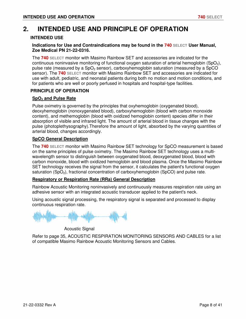
Rainbow Acoustic Monitoring noninvasively and continuously measures respiration rate using an adhesive sensor with an integrated acoustic transducer applied to the patient's neck.
Using acoustic signal processing, the respiratory signal is separated and processed to display continuous respiration rate.
Acoustic Signal
Refer to page 35, ACOUSTIC RESPIRATION MONITORING SENSORS AND CABLES for a list of compatible Masimo Rainbow Acoustic Monitoring Sensors and Cables.

INTENDED USE AND OPERATION 740 SELECT
21-22-0332 Rev A Page 9 of 41
METHOD OF OPERATION
The instrument containing Rainbow SET Technology is turned on. A sensor is attached to a patient’s finger. The other end of the sensor is attached to a patient cable. The other end of the patient cable is connected to the instrument.
The instrument will begin continuously displaying the patient’s pulse rate and SpO2 value. Depending on the type and/or configuration of the instrument, monitoring information would also include SpCO and PVI. The practitioner can then use the information to help assess the condition of the patient and as an aide in determining if any intervention is required by the practitioner.
Once the practitioner determines the patient no longer requires monitoring, the cable is disconnected from the sensor, the sensor is removed (and disposed of if it is a single use device), and the power to the instrument is turned off.
Respiratory or Respiration Rate (RRa). A sensor is attached to a patient’s neck. The other end of the sensor is connected to a patient cable. The other end of the cable is connected to the Dual Channel cable. The Dual Channel cable is then connected to the instrument.
The instrument will begin continuously displaying the patient’s respiratory/ respiration rate. The practitioner can then use the information to help assess the condition of the patient and as an aide in determining if any intervention is required by the practitioner. Once the practitioner determines the patient no longer requires monitoring, the patient cable is disconnected from the sensor, the sensor is disposed and the power to the instrument is turned off
MASIMO PATENTS
For the current list of Masimo Patents please refer to: www.masimo.com/patents.htm
NO IMPLIED LICENSE
Possession or purchase of this device does not convey any express or implied license to use the device with unauthorized sensors or cables which would, alone or in combination with this device, fall within the scope of one or more of the patents relating to this device.

SYMBOLS 740 SELECT
21-22-0332 Rev A Page 10 of 41
3. SYMBOLS
Figure 1 illustrates the location and order of applied Masimo Rainbow SET Labels. Table 1 indicates the Masimo Rainbow SET Symbols that will appear on the labels that appear on the left side of 740 SELECT monitor, adjacent to the SpO2 connector.
PVI Label
RRa Label
SpCO Label
Masimo SpO2 Connector
Figure 1: Example of applied Rainbow Labels
Indicates the Masimo Rainbow SET PVI parameter is enabled
Indicates the Masimo Rainbow SET RRa parameter is enabled
Indicates the Masimo Rainbow SET SpCO parameter is enabled
Table 1: Symbols on the monitor

MASIMO RAINBOW SET MONITORING 740 SELECT
21-22-0332 Rev A Page 11 of 41
4. MASIMO RAINBOW SET MONITORING
Note: The following Warnings and Cautions are directed toward the Masimo Rainbow SET monitoring function. Additional Warnings and Cautions for the 740 SELECT monitor are found in the 740 SELECT User Manual, Zoe Medical PN 21-22-0316.
Note: A Pulse CO-Oximeter or pulse oximeter, referred to here, and the 740 SELECT monitor
with Masimo Pulse Oximetry are the same device.
WARNINGS:
Warning: Pulse rate measurement is based on the optical detection of a peripheral flow pulse and therefore may not detect certain arrhythmias. The pulse oximeter should not be used as a replacement or substitute for ECG based arrhythmia analysis.
Warning: A Pulse CO-Oximeter should be considered an early warning device. As a trend towards patient hypoxemia is indicated, blood samples should be analyzed by laboratory instruments to completely understand the patient’s condition.
Warning: Interfering Substances: Dyes or any substance containing dyes, that change usual blood pigmentation may cause erroneous readings.
Warning: Elevated levels of Total Bilirubin may lead to inaccurate SpO2and SpCO measurements.
Warning: Motion artifact may lead to inaccurate SpCO measurements.
Warning: Severe anemia may cause erroneous SpO2 readings.
Warning: Very low arterial Oxygen Saturation (SpO2) levels may cause inaccurate SpCO measurements.
Warning: With very low perfusion at the monitored site, the readings may read lower than core arterial oxygen saturation.
Warning: Do not use tape to secure the sensor to the site; this can restrict blood flow and cause inaccurate readings. Use of additional tape can cause skin damage or damage the sensor.
Warning: If the sensor is wrapped to tightly or supplemental tape is used, venous congestion/pulsations may occur causing erroneous readings.
Warning: Venous congestion may cause under reading of actual arterial oxygen saturation. Therefore, assure proper venous outflow from monitored site. Sensor should not be below heart level (e.g., sensor on hand of a patient in a bed with arm dangling to the floor).
Warning: Venous pulsations may cause erroneous low readings (e.g., tricuspid value regurgitation).
Warning: Loss of pulse signal can occur when:
o The sensor is too tight.
o The patient has hypotension, severe vasoconstriction, severe anemia, or hypothermia.
o There is arterial occlusion proximal to the sensor.
o The patient is in cardiac arrest or is in shock
Warning: The pulsations from intra-aortic balloon support can be additive to the pulse rate on the pulse oximeter pulse rate display. Verify patient's pulse rate against the ECG heart rate.

MASIMO RAINBOW SET MONITORING 740 SELECT
21-22-0332 Rev A Page 12 of 41
Warning: Misapplied sensors or sensors that become partially dislodged may cause either over or under reading of actual arterial oxygen saturation.
Warning: Avoid placing the sensor on any extremity with an arterial catheter or blood pressure cuff.
Warning: High intensity extreme lights (including pulsating strobe lights) directed on the sensor may not allow the Pulse CO-Oximeter to obtain readings.
Warning: The Pulse CO-Oximeter can be used during defibrillation, but the readings may be inaccurate for up to 20 seconds.
Warning: Before use, carefully read the sensor's Directions for Use.
Warning: Tissue damage can be caused by incorrect application or use of a sensor, for example by wrapping the sensor too tightly. Inspect the sensor site as directed in the sensor's Directions for Use to ensure skin integrity and correct positioning and adhesion of the sensor.
Warning: The Pulse CO-Oximeter is NOT intended for use as an apnea monitor.
Warning: To avoid cross contamination only use Masimo single use sensors on the same patient.
Warning: Unless otherwise specified, do not sterilize sensors or patient cables by irradiation, steam, autoclave or ethylene oxide.
Warning: See the cleaning instructions in the directions for use for the Masimo re-useable sensors.
Warning: This equipment has been tested and found to comply with the limits for medical devices to the EN 60601-1-2, Medical Device Directive 93/42/EEC. These limits are designed to provide reasonable protection against harmful interference in a typical medical installation. This equipment generates, uses and can radiate radio frequency energy and, if not installed and used in accordance with the instructions, may cause harmful interference to other devices in the vicinity. However, there is no guarantee that interference will not occur in a particular installation. If this equipment does cause harmful interference to other devices, which can be determined by turning the equipment off and on, the user is encouraged to try to correct the interference by one or more of the following measures:
o Reorient or relocate the receiving device
o Increase the separation between the equipment
o Consult the manufacturer for help
Warning: Do not place the Pulse CO-Oximeter on electrical equipment that may affect the Pulse CO-Oximeter, preventing it from working properly.
Warning: Electric shock hazard. Only a qualified operator may perform maintenance procedures specifically described in this Manual.
Warning: To protect against injury from electric shock, follow the directions below:
o Avoid placing the device on surfaces with visible liquid spills
o Always turn off and disconnect the power cord from the AC power supply before cleaning the device
o Use cleaning solutions sparingly
Warning: To ensure patient electrical isolation, connect only to other equipment with electrically isolated circuits.

MASIMO RAINBOW SET MONITORING 740 SELECT
21-22-0332 Rev A Page 13 of 41
Warning: Do not use damaged sensors or patient cables. Do not use a sensor or patient cable with exposed optical or electrical components.
Warning: Do not attempt to reprocess, recondition or recycle any Masimo sensors or patient cables as these processes may damage the electrical components, potentially leading to harm.
Warning: Explosion hazard - Do not use the Pulse CO-Oximeter in the presence of flammable anesthetics or other flammable substance in combination with air, oxygen-enriched environments, or nitrous oxide.
Warning: The Pulse CO-Oximeter is to be operated by qualified personnel only. The Operators manual, directions for use, all precautionary information, and specifications should be read before use.
Warning: As with all medical equipment, carefully route patient cabling to reduce the possibility of patient entanglement or strangulation.
Warning: Do not lift the CO-Oximeter by the patient cable.
Warning: Always remove the sensor from the patient and completely disconnect the patient from the Pulse CO-Oximeter before bathing the patient.
Warning: Do not expose the Pulse CO-Oximeter to excessive moisture such as direct exposure to rain. Excessive moisture can cause the Pulse CO-Oximeter to perform inaccurately or fail.
Warning: Do not immerse the sensor or patient cable in water or, solvents, or cleaning solutions (The sensors and connectors are not waterproof).
DEVICES EQUIPPED WITH RAINBOW ACOUSTIC MONITORING:
Warning: SpO2 monitoring is required when monitoring RRa (Acoustic Respiration).
Warning: Excessive ambient noise may affect the accuracy of the respiration rate reading from the Acoustic Respiration Sensor.
Warning: Ensure the RAM Dual rainbow Cable is physically intact, with no broken or frayed wires or damaged parts. Visually inspect the cable and discard if cracks or discolorations are found. Never use damaged cable or one with exposed electrical contacts.
Warning: To avoid damage to the RAM Dual rainbow Cable, always hold the cable by the connector rather than the cable when connecting or disconnecting either end.
Warning: Always refer to the rainbow Acoustic Monitoring enabled devices Operators Manual for additional and complete instructions.

MASIMO RAINBOW SET MONITORING 740 SELECT
21-22-0332 Rev A Page 14 of 41
CAUTIONS:
Caution: Do not use the Pulse CO-Oximeter or oximetry sensors during magnetic resonance imaging (MRI) scanning. Induced current could potentially cause burns. The Pulse CO-Oximeter may affect the MRI image, and the MRI unit may affect the accuracy of the oximetry measurements.
Caution: If using pulse CO-oximetry during full body irradiation, keep the sensor out of the irradiation field. If the sensor is exposed to the irradiation, the reading might be inaccurate or the unit might read zero for the duration of the active irradiation period.
Caution: Exercise caution when applying a sensor to a site with compromised skin integrity. Applying tape or pressure to such a site may reduce circulation and/or cause further skin deterioration.
Caution: Circulation distal to the sensor site should be checked routinely.
Caution: A functional tester cannot be utilized to assess the accuracy of the Pulse CO-Oximeter or any sensors.
Caution: Do not modify or alter the sensor in any way. Alterations or modification may affect performance and/or accuracy
DEVICES EQUIPPED WITH RAINBOW ACOUSTIC MONITORING:
Caution: The RAM Dual rainbow Cable is designed to directly interface with validated rainbow Acoustic Monitoring enabled devices or with validated rainbow Acoustic Monitoring enabled multi-parameter monitors.
Caution: Failure to properly connect the RAM Dual rainbow Cable to the rainbow Acoustic Monitoring enabled device or multi-parameter monitor may result in intermittent readings, inaccurate results, or no reading.

MASIMO RAINBOW SET MONITORING 740 SELECT
21-22-0332 Rev A Page 15 of 41
DISPLAY OF RAINBOW PARAMETERS
Figure 2 illustrates all Masimo Rainbow SET parameter disabled – Only SpO2 & PR enabled.
Figure 2: All Rainbow Parameter Disabled
Figure 3 illustrates the Setup SpO2 menu when the SpO2 field is pressed. From this menu, all the Rainbow Parameters may be Disabled [Off] or Enabled [On]. Figure 3 illustrates the Rainbow Parameters (SpCO, RRA & PVI) as enabled for display.
Rainbow Parameters selection:
Disabled [Off]
Enabled [On]
Available Rainbow Parameters: SpCO, RRA & PVI
Figure 3: Setup SpO2 Menu

MASIMO RAINBOW SET MONITORING 740 SELECT
21-22-0332 Rev A Page 16 of 41
SpCO MONITORING
SpCO allows clinicians to noninvasively and immediately diagnose, monitor and treat patients poisoned by carbon monoxide, when this parameter is enabled and a rainbow multi-LED sensor capable of SpCO measurement is attached to the patient.
SpCO represents the percentage of Carboxyhemoglobin within the blood as measured by the Masimo rainbow multi-LED sensors which offer noninvasive SpCO measurements.
Figure 4 illustrates the Masimo Rainbow SET SpCO parameter that will appear on the 740 SELECT monitor screen.
Figure 4: SpCO Parameter enabled
Figure 5 illustrates the Setup SpCO menu when the SpCO field is pressed. From this menu, the Lower and Upper SpCO Alarm Limits may be adjusted. Auto limits and disabling SpCO Alarms may be selected in this menu as well.
Figure 5: Setup SpCO Menu

MASIMO RAINBOW SET MONITORING 740 SELECT
21-22-0332 Rev A Page 17 of 41
ALARM LIMIT VALUES
Table 2 lists the Default SpCO Alarm Limits for Adult, Pediatric, and Neonatal. SpCO Alarm Limits will operate on the parameters for the current monitor patient mode.
SpCO Adult Pediatric Neonate
Upper 10 10 10
Lower Off Off Off
Table 2: SpCO Default Alarm Limits
To set the SpCO Alarm limits:
1) Touch the SpCO Numeric field.
2) Adjust the desired SpCO High or Low Limit value.
• The SpCO Upper and Lower Alarm Limits can be adjusted independently.
• The SpCO Upper and Lower Alarm Limit can be set to “Off”.
Warning: Setting the SpCO Upper or Lower Alarm Limit to “Off” will not generate any visual or audible indication of an alarm condition.
3) Touch OK to accept or Cancel to ignore the selection.
4) Touch the Home touch area to return to the Main screen.
AUTO (set) ALARM LIMITS
Upper and lower alarm limits for each parameter can be set automatically using the Auto feature, which provides a structure to establish alarms limits based upon your patient’s current measured value.
To enable Auto limits, open the applicable parameter Setup Window and touch the “AUTO” key on the same line with the parameter (refer to Table 3 for SpCO percentages).
Parameter
Alarm Limit Adjustment
(x% of the current measured value
Lower Upper
SpCO 95% 100%
Table 3: SpCO Auto Alarm Limit Adjustment
SpCO DURING PATIENT MOTION
The 740 SELECT monitor displays SpCO measurements during patient motion. However, because of the changes in the physiological parameters such as blood volume, arterial-venous coupling, etc. that occur during patient motion, the accuracy of the measurement may not be reliable during excessive motion. In this case, the measurement value for SpCO displays as dashes (---) and a message (Low SpCO SIQ) displays to alert the clinician that the instrument does not have confidence in the value due to poor signal quality caused by excessive motion or other signal interference.

MASIMO RAINBOW SET MONITORING 740 SELECT
21-22-0332 Rev A Page 18 of 41
RAINBOW ACOUSTIC MONITORING (RAM/RRa) MONITORING
Acoustic Respiration monitoring uses acoustic technology to continually measure a patient’s respiration rate based on airflow sounds generated in the upper airway during the breathing cycle of inspiration and expiration. The Acoustic Sensor translates airflow sounds generated in the upper airway to an electrical signal that can be processed to produce a respiration rate, measured as breaths per minute.
Respiratory sounds include sounds related to respiration such as breath sounds (during inspiration and expiration), adventitious sounds, cough sounds, snoring sounds, sneezing sounds, and sounds from the respiratory muscles [1].
These respiratory sounds often have different characteristics depending on the location of recording [2] and they originate in the large airways where air velocity and air turbulence induce vibration in the airway wall. These vibrations are transmitted, for example, through the lung tissue, thoracic wall and trachea to the surface where they may be heard with the aid of a stethoscope, a microphone or more sophisticated devices.
RAINBOW ACOUSTIC MONITORING ARCHITECTURE
The following figure illustrates how a respiratory sound produced by a patient can be turned into a numerical measurement that corresponds to a respiratory parameter.
Figure 6: Rainbow Acoustic Monitoring Architecture
PATIENT
The generation of respiratory sounds is primarily related to turbulent respiratory airflow in upper airways. Sound pressure waves within the airway gas and airway wall motion contribute to the vibrations that reach the body surface and are recorded as respiratory sounds.
Although the spectral shape of respiratory sounds varies widely from person to person, it is often reproducible within the same person, likely reflecting the strong influence of individual airway anatomy [2-6].
RRa SENSOR
Masimo Rainbow SET Acoustic Monitoring utilizes an adhesive sensor with an integrated acoustic transducer that is applied to the patient’s neck. The respiratory signal is separated and processed using signal extraction technology to display continuous respiration rate. The Rainbow Acoustic Sensor (refer to Figure 7) captures respiratory sounds (and other biological sounds) much like a microphone does. When subjected to a mechanical strain, (e.g., surface vibrations generated during breathing), the sensor becomes electrically polarized.

MASIMO RAINBOW SET MONITORING 740 SELECT
21-22-0332 Rev A Page 19 of 41
Figure 7: Rainbow Acoustic Sensor
The degree of polarization is proportional to the applied strain. The output of the sensor is an electric signal that includes a sound signal that is modulated by inspiratory and expiratory phases of the respiratory cycle.
The Rainbow Acoustic Sensor detects upper airway acoustical signals produced by the turbulent airflow that occurs during both inhalation and exhalation. Figure 8 is a sample of the acoustic signal and shows six complete breaths, each one characterized by a pair of envelopes, the first during inhalation and the second during exhalation.
Figure 8: Acoustic signal showing several complete breaths
Note the strength of the breathing envelope in relation to the baseline environmental noise signal.
The amplitude of the acoustic signal is related to the strength of the breath, sensor placement, and conduction of sound from the trachea through the muscle and skin in the patient’s neck to the sensor.
The mechanical coupling of the sensor to the body surface helps separate the breathing signal from ambient background noise. Signal processing algorithms convert these acoustic patterns into breath cycles and calculate the respiration rate. Rainbow Acoustic Monitoring algorithms distinguish breath patterns from other biological signals such as carotid pulses, vocalization, coughs, and ambient background noise, as well as respiratory synchronous signals such a snoring or wheezing to produce a reliable measurement. The algorithm constantly measures breath signal strength compared to background noise. When the signal falls below the minimum threshold, as could occur during shallow breathing (hypopnea), the algorithm forces the respiration rate to zero resulting in an alarm condition.
The acoustic waveform amplitude is affected by a variety of factors preventing comparisons between patients for other physiologic determinations, however changes within the same patients may indicate relative physiologic changes such as changes in Tidal Volume.
As a safety precaution, the RRa value is only available when a valid SpO2 saturation value is measured. However, the Acoustic Display Waveform is displayed, regardless of whether a SpO2 value is valid or not.
MASIMO RAINBOW SET MONITORING 740 SELECT
21-22-0332 Rev A Page 20 of 41
ACQUISITION SYSTEM
The acquisition system converts the electric signal provided by the sensor into a digital signal. This format allows the signal to be processed by a computing device.
SIGNAL PROCESSING
The digital signal produced by the acquisition system is converted into a measurement that corresponds to the respiratory parameter of interest. As shown in the previous figure, this can be performed by, for example, determining the digital signal envelope or outline which in turn may be utilized to determine the respiratory rate. In this way, a real-time, continuous breath rate parameter can be obtained and displayed on a monitor which, in many cases, may be real-time and continuous.
The respiratory cycle envelope signal processing principle is similar to methods that sample airway gasses and subsequently determine a respiratory rate.
[1] A.R.A. Sovijärvi, F. Dalmasso, J. Vanderschool, L.P. Malmberg, G. Righini, S.A.T. Stoneman. Definition of terms for applications of respiratory sounds. Eur Respir Rev 2000; 10:77, 597-610.
[2] Z. Moussavi. Fundamentals of respiratory sounds analysis. Synthesis lectures on biomedical engineering #8. Morgan & Claypool Publishers, 2006.
[3] Olsen, et al. Mechanisms of lung sound generation. Semin Respir Med 1985; 6: 171-179.
[4] Pastercamp H, Kraman SS, Wodicka GR. Respiratory sounds – Advances beyond the stethoscope. Am J Respir Crit Care Med 1977; 156: 974-987.
[5] Gavriely N, Cugell DW. Airflow effects on amplitude and spectral content of normal breath sounds. J Appl Physiol 1996; 80: 5-13.
[6] Gavrieli N, Palti Y, Alroy G. Spectral characteristics of normal breath sounds. J Appl Physiol 1981; 50: 307-314.

MASIMO RAINBOW SET MONITORING 740 SELECT
21-22-0332 Rev A Page 21 of 41
Figure 9 illustrates the Masimo Rainbow SET RRa parameter that will appear on the 740 SELECT monitor screen.
Figure 9: RRa Parameter enabled
Figure 10 illustrates the Setup RRa menu when the RRa field is pressed. From this menu, the Lower and Upper RRa Alarm Limits may be adjusted. Auto limits, disabling RRa Alarms, Average Time, Freshness timeout, Pause Time and Alarm Delay may be selected in this menu as well.
Figure 10: Setup RRa Menu

MASIMO RAINBOW SET MONITORING 740 SELECT
21-22-0332 Rev A Page 22 of 41
ALARM LIMIT VALUES
Table 4 lists the Default RRa Alarm Limits for Adult, Pediatric, and Neonatal. RRa Alarm Limits will operate on the parameters for the current monitor patient mode.
RRa Adult Pediatric Neonate
Upper 30 30 30
Lower 6 6 6
Table 4: RRa Default Alarm Limits
To set the RRa Alarm limits:
1) Touch the RRa Numeric field.
2) Adjust the desired RRa High or Low Limit value.
• The RRa Upper and Lower Alarm Limits can be adjusted independently.
• The RRa Upper and Lower Alarm Limit can be set to “Off”.
Warning: Setting the RRa Upper or Lower Alarm Limit to “Off” will not generate any visual or audible indication of an alarm condition.
3) Touch OK to accept or Cancel to ignore the selection.
4) Touch the Home touch area to return to the Main screen.
AUTO (set) ALARM LIMITS
Upper and lower alarm limits for each parameter can be set automatically using the Auto feature, which provides a structure to establish alarms limits based upon your patient’s current measured value.
To enable Auto limits, open the applicable parameter Setup Window and touch the “AUTO” key on the same line with the parameter (refer to Table 5 for RRa percentages).
Parameter
Alarm Limit Adjustment
(x% of the current measured value
Lower Upper
RRa 95% 100%
Table 5: RRa Auto Alarm Limit Adjustment
AVERAGE time
The user-selectable RRA averaging feature allows the clinician to select the desired level of visibility to subtle variations in the measured value. This setting allows the clinician to fine tune RRa responsiveness to achieve the desired level of visibility to rapid variations in measured respiration rate values.
User Selectable settings: None, Fast, Medium, Slow (Default) or Trending.

MASIMO RAINBOW SET MONITORING 740 SELECT
21-22-0332 Rev A Page 23 of 41
FRESHNESS TIMEOUT
This feature is intended to minimize alarms during artifact conditions that preclude RRa measurements, such as patient talking, eating, etc.
RRa Freshness Timeout refers to the maximum amount of time the system will display the last known RRa value when artifact precludes ongoing RRa measurements before the RRa value is invalidated (i.e., such as dashes or ???).
If the user selected Refresh Timeout period is exceeded, the 740 SELECT monitor generates an audio and visual notification.
User Selectable Settings: 0, 1, 5 (Default), 10 or 15 minutes.
PAUSE TIME
RRa Pause Time refers to the time the system will wait between breaths for the patients to resume breathing before alarming.
The RRa Pause Time allows the clinician to adjust the alarm system to accommodate various breathing patterns by setting the maximum allowed pause time between breaths.
The 740 SELECT monitor provides an audible and visual notification if the selected Pause Time has been exceeded.
Warning: Pause Time is not intended to be used as an apnea monitor.
User Selectable Settings: 15, 20, 25, 30 (Default), 35, or 40 seconds.
ALARM DELAY
Many changes in RR are real but transitory. In some cases, such transitory changes may not require clinical action / intervention (“non-actionable”).
The RRa Alarm Delay setting allows the RRa value to exceed the current set alarm limit for a user selectable duration before an audible alarm is generated
The RRa Alarm Delay setting only affects RRa audible alarm limits.
User Selectable Settings: 0, 10, 15, 30 (Default) or 60 seconds.
Refer to www.masimo.com for Masimo Technical Bulletins, White Papers discussing the use and benefits RRa.

MASIMO RAINBOW SET MONITORING 740 SELECT
21-22-0332 Rev A Page 24 of 41
BEST PRACTICES CHECKLIST FOR ACOUSTIC RRa COMPARISONS
• Acoustic Sensor placement - The Acoustic sensor has a small black arrow on the front (item 1 in Figure 11 below), when placing the sensor the black arrow should point forward to the anterior of subject’s body.
Figure 11: Acoustic Sensor
• Ensure placement site is hair-free, clean of debris, and dry prior to sensor placement. Use an alcohol swab to clean the neck area, if needed.
• The sensor pad (item 2 in the Figure 11 above) should be placed to either side of the larynx, in the area just above the thyroid cartilage and below the jaw line (see Figure 12 below). Ensure that there are no skin folds under the sensor pad.
Figure 12: Sensor pad locations
• For pediatric subjects that have limited neck space, the sensor may be placed on the right side of chest, underneath clavicle. The sensor should not be touching the clavicle.
• Place sensor tape on skin. Gently press on sensor tape from center outward so adhesive forms a good contact with patient's skin. Ensure there are no skin folds or air gaps under sensor pad.
• Remove the release liner from the anchor pad and place the anchor pad on patient’s side of the neck; route the sensor cable in front of patient. Do not place anchor pad on clothing.
• RRa Monitoring - If RRa values are not displayed after 2 minutes or if the RRa value has dropped out, check the following:
� Confirm appropriate sensor placement, orientation and site selections;
� Confirm that optical pulse-oximeter sensor is placed properly on the patient's finger;
� Confirm that all cables are plugged in at each of the various connection points and hubs;
� Auscultate with stethoscope to listen for air sounds on the side opposite sensor. If breath sounds are present, remove sensor and replace with new sensor on opposite side of neck;
� Change the sensor out if RRa value continues to not display; and
� Verify that there is not excessive hair or a gap between the sensor and the neck and that it is placed.

MASIMO RAINBOW SET MONITORING 740 SELECT
21-22-0332 Rev A Page 25 of 41
• Simultaneously record the RRa and respiratory rates and from other methods. If comparing RRa to capnography respiration rate, a mask is recommended. Sidestream methods with a nasal cannula are not recommended because of dilution effect in the supplemental flow of gasses, inability to measure both nasal and oral airflow, and nasal cannula mis-positioning. When recording values, confirm that there are no SIQ messages displayed on the device.
• Suggested directions to record manual respiration rate are as follows:
� Use stethoscope to listen for breath sounds, count each breath cycle as one breathe, count for 60 seconds; or
� Alternate method to stethoscope, count the number of chest rises/inhalations during a 60 second period. Record manual respiration rate to compare with RRa.
• Adjust respiratory pause settings as necessary, default is 30 seconds (options are: 15, 20, 25, 30, 35, or 40 seconds).
• Document patient events and time of event. Include events that may affect performance, these include:
� Patient talking, picking at the sensor or nasal cannula, excessive movement, ambient noise present, fans or air blowing at sensor.
• Inaccurate measurements may be caused by:
� Excessive ambient or environmental noise (patient speaking, room noise);
� Improper sensor placement;
� Cable disconnection; or
� Movement, picking, or air blowing at sensor.

MASIMO RAINBOW SET MONITORING 740 SELECT
21-22-0332 Rev A Page 26 of 41
PVI MONITORING
Pleth Variability Index (PVI) is a dynamic measurement to help assess physiology and fluid responsiveness. PVI provides a noninvasive, continuous method to help clinicians manage fluid responsiveness in sedated adult surgical and intensive care patients under positive pressure ventilation with a normal sinus rhythm.
PVI is a measure of the dynamic changes in the Perfusion Index (PI) that occur during the respiratory cycle. The PVI calculation is accomplished by measuring changes in PI over a time interval where one or more complete respiratory cycles have occurred.
PVI CALCULATION:
PVI is displayed as a percentage (0-100%).
The lower the number, the less variability there is in the PI over a respiratory cycle.
PI is the ratio of the pulsatile blood flow to the non-pulsatile or static blood in peripheral tissue. PI represents a noninvasive measure of peripheral perfusion that can be continuously and noninvasively obtained from a pulse oximeter.
Refer to www.masimo.com for Masimo Technical Bulletins and White Papers discussing the use and benefits of PVI and PI.

MASIMO RAINBOW SET MONITORING 740 SELECT
21-22-0332 Rev A Page 27 of 41
Figure 13 illustrates the Masimo Rainbow SET PVI parameter that will appear on the 740 SELECT monitor screen.
Figure 13: PVI Parameter enabled
Figure 14 illustrates the Setup PVI menu when the PVI field is pressed. From this menu, the Lower and Upper PVI Alarm Limits may be adjusted. Auto limits and disabling PVI Alarms may be selected in this menu as well.
Figure 14: Setup PVI Menu

MASIMO RAINBOW SET MONITORING 740 SELECT
21-22-0332 Rev A Page 28 of 41
ALARM LIMIT VALUES
Table 6 lists the Default PVI Alarm Limits for Adult, Pediatric, and Neonatal. PVI Alarm Limits will operate on the parameters for the current monitor patient mode.
PVI Adult Pediatric Neonate
Upper Off Off Off
Lower Off Off Off
Table 6: PVI Default Alarm Limits
To set the PVI Alarm limits:
1) Touch the PVI Numeric field.
2) Adjust the desired PVI High or Low Limit value.
• The PVI Upper and Lower Alarm Limits can be adjusted independently.
• The PVI Upper and Lower Alarm Limit can be set to “Off”.
Warning: Setting the PVI Upper or Lower Alarm Limit to “Off” will not generate any visual or audible indication of an alarm condition.
3) Touch OK to accept or Cancel to ignore the selection.
4) Touch the Home touch area to return to the Main screen.
AUTO (set) ALARM LIMITS
Upper and lower alarm limits for each parameter can be set automatically using the Auto feature, which provides a structure to establish alarms limits based upon your patient’s current measured value.
To enable Auto limits, open the applicable parameter Setup Window and touch the “AUTO” key on the same line with the parameter (refer to Table 7 for PVI percentages).
Parameter
Alarm Limit Adjustment
(x% of the current measured value
Lower Upper
PVI 95% 100%
Table 7: PVI Auto Alarm Limit Adjustment

MASIMO RAINBOW SET MONITORING 740 SELECT
21-22-0332 Rev A Page 29 of 41
MULTIPLE RAINBOW PARAMETERS ENABLED
Figure 15 illustrates the Main screen with SpCO & RRa parameters enabled. Figure 16 illustrates the Main screen with SpCO, RRa & PVI parameters enabled. Each numeric field still opens to the appropriate parameter setup menu.
Figure 15: Main Screen w/SpCO & RRa enabled
Figure 16: Main Screen w/SpCO, RRa & PVI enabled

MASIMO RAINBOW SET MONITORING 740 SELECT
21-22-0332 Rev A Page 30 of 41
ERROR MESSAGES ON THE DISPLAY
SpCO ERROR MESSAGES
Table 8 indicates the Masimo Rainbow SpCO Error Messages that may appear on the monitor display.
Message SpCO Possible Cause Suggested Action
SpCO check sensor --- • Defective or
unrecognized sensor • Replace sensor
SpCO unplugged <blank> • Sensor is disconnected • Reconnect the sensor
SpCO problem detected --- • Masimo board not
responding or reports failure
• Power cycle the monitor, if problem persists, contact service
SpCO check sensor placement
--- • No finger in probe or too
much light • Adjust placement of the
sensor
SpCO artifact --- • Masimo board reports
interference • Adjust placement of the
sensor, advise patient to remain still
SpCO low perfusion ---
• Masimo board is reporting low perfusion and no numeric value
• Adjust placement of the sensor, check for cold fingers or other reason that could cause low perfusion
SpCO low signal IQ --- • Masimo board is
reporting low signal IQ and no numeric value
• Adjust placement of the sensor, advise patient to remain still
SpCO < [lower limit] [number]
• The patient's SpCO value has fallen below the current lower alarm limit
• Check the patient and provide any necessary clinical care
• Change the alarm limit if it is no longer clinically appropriate
SpCO > [upper limit] [number]
• The patient's SpCO value has risen above the current upper alarm limit
• Check the patient and provide any necessary clinical care
• Change the alarm limit if it is no longer clinically appropriate
Table 8: SpCO Error Messages

MASIMO RAINBOW SET MONITORING 740 SELECT
21-22-0332 Rev A Page 31 of 41
RRa ERROR MESSAGES
Table 9 indicates the Masimo Rainbow RRa Error Messages that may appear on the monitor display.
Message RRa Possible Cause Suggested Action
RRa check sensor --- • Defective or
unrecognized sensor • Replace sensor
RRa unplugged <blank> • Sensor is disconnected • Reconnect the sensor
RRa problem detected --- • Masimo board not
responding or reports failure
• Power cycle the monitor, if problem persists, contact service
RRa check sensor placement --- • Incorrect sensor
placement • Adjust placement of the
sensor
RRa artifact ---
• Masimo board reports interference
• Adjust placement of the sensor, advise patient to remain still and quiet, reduce ambient noise
RRa cannot measure --- • RRa is suppressed due
to lack of Pulse Oximetry data
• Adjust placement of the SpO2 sensor, advise patient to remain still
RRa low signal IQ ---
• Masimo board is reporting low signal IQ and no numeric value
• Adjust placement of the sensor, advise patient to remain still and quiet, reduce ambient noise
RRa < [lower limit] [number]
• The patient's RRa value has fallen below the current lower alarm limit
• Check the patient and provide any necessary clinical care
• Change the alarm limit if it is no longer clinically appropriate
RRa > [upper limit] [number]
• The patient's RRa value has risen above the current upper alarm limit
• Check the patient and provide any necessary clinical care
• Change the alarm limit if it is no longer clinically appropriate
Table 9: RRa Error Messages

MASIMO RAINBOW SET MONITORING 740 SELECT
21-22-0332 Rev A Page 32 of 41
PVI ERROR MESSAGES
Table 10 indicates the Masimo Rainbow PVI Error Messages that may appear on the monitor display.
Message PVI Possible Cause Suggested Action
PVI check sensor --- • Defective or
unrecognized sensor • Replace sensor
PVI unplugged <blank> • Sensor is disconnected • Reconnect the sensor
PVI problem detected --- • Masimo board not
responding or reports failure
• Power cycle the monitor, if problem persists, contact service
PVI check sensor placement --- • No finger in probe or too
much light • Adjust placement of the
sensor
PVI artifact --- • Masimo board reports
interference • Adjust placement of the
sensor, advise patient to remain still
PVI low signal IQ --- • Masimo board is
reporting low signal IQ and no numeric value
• Adjust placement of the sensor, advise patient to remain still
PVI < [lower limit] [number]
• The patient's PVI value has fallen below the current lower alarm limit
• Check the patient and provide any necessary clinical care
• Change the alarm limit if it is no longer clinically appropriate
PVI > [upper limit] [number]
• The patient's PVI value has risen above the current upper alarm limit
• Check the patient and provide any necessary clinical care
• Change the alarm limit if it is no longer clinically appropriate
Table 10: PVI Error Messages

ACCESSORIES 740 SELECT
21-22-0332 Rev A Page 33 of 41
5. ACCESSORIES & RAINBOW PARAMETER INSTALLATION
Contact our Customer Service Department or go to our website for the latest product information. Refer to page 3 for email, website and phone number information.
MASIMO RAINBOW SET SENSOR AND PATIENT CABLES
Table 11 indicates the Masimo Rainbow SET Sensors and Cables to be used with 740 SELECT monitor.
RAINBOW SENSORS
Catalog No. Description Unit Reference #
01-02-0826 M-LNCS DCI, Adult SpO2 Reusable Sensor (>30 kg)
Adult Reusable Sensor, 3 ft.
Non-sterile, Weight > 30 kg
This product does not contain natural rubber latex
Box / 1 2501
01-02-0827 Rainbow Patient Cable, RC-12
Rainbow 20-pin Patient Cable, 12 ft
For use with Rainbow and M-LNCS sensors
Box / 1 2404
01-02-0828 Rainbow Patient Cable, RC-4
Rainbow 20-pin Patient Cable, 4 ft
For use with Rainbow and M-LNCS sensors
Box / 1 2406

ACCESSORIES 740 SELECT
21-22-0332 Rev A Page 34 of 41
Catalog No. Description Unit Reference #
01-02-0939 M-LNCS™ DCIP Pediatric/Slender Digit Reusable Sensor, 3 ft
Non-sterile, Weight 10 kg – 50 kg
This product does not contain natural rubber latex
Box / 1 2502
RAINBOW REUSABLE SENSORS - SpCO WITH SPO2
Catalog No. Description Unit Reference #
01-02-0829 Rainbow DCI-3, Adult Reusable Sensor, (SpCO, SpMet, SpO2), 3 ft
Non-sterile, Weight > 30 kg
This product does not contain natural rubber latex
Box / 1 2696
01-02-0830 Rainbow DCIP-3, Pediatric Reusable Sensor, (SpCO, SpMet, SpO2), 3 ft
Non-sterile, Weight 10 kg - 50 kg
This product does not contain natural rubber latex
Box / 1 2697

ACCESSORIES 740 SELECT
21-22-0332 Rev A Page 35 of 41
ACOUSTIC RESPIRATION MONITORING SENSORS AND CABLES
Catalog No. Description Unit Reference #
01-02-0831 RAM Dual Cable RC‐10 (Rainbow & RAM)
(Using M-LNCS SpO2), 10 ft
Box / 1 3660
01-02-0832 RAM Dual Cable LNC‐10 (SpO2 & RAM only)
(Using LNCS SpO2), 10 ft
Box / 1 3661
01-02-0834 RAS-125c, Acoustic Respiration Cloth Sensor Adult Adhesive Sensors (RRa)
Single patient use, Non-sterile
Weight > 30kg
This product does not contain natural rubber latex
Box / 10 2902

ACCESSORIES 740 SELECT
21-22-0332 Rev A Page 36 of 41
Catalog No. Description Unit Reference #
01-02-0937 RAS-125c, Acoustic Respiration Cloth Sensor
Adult/Pediatric Adhesive Sensors (RRa)
Non-sterile, Single patient use
Weight > 10kg
This product does not contain natural rubber latex.
Box / 10 3475
01-02-0938 RAS-125c, Short Term Monitoring Acoustic Respiration Cloth Sensor
Adult/Pediatric Adhesive Sensors (RRa)
Non-sterile, Single patient use
Weight > 10kg
This product does not contain natural rubber latex
Box /10 3483
Table 11: Rainbow SET Sensors and Cables

ACCESSORIES 740 SELECT
21-22-0332 Rev A Page 37 of 41
MASIMO RAINBOW ENABLING
Table 12 indicates the Zoe Medical Part Number required to enable the various Masimo Rainbow SET Parameters in a 740 SELECT monitor:
FACTORY INSTALLATION
Catalog No. Description
01-02-0835 Masimo Carboxyhemoglobin (SpCO) Factory Enable (Ref 3879)
01-02-0836 Masimo Pleth Variability Index (PVI) Factory Enable (Ref 3883)
01-02-0837 Masimo Acoustic Respiration Rate (RRa) Factory Enable (Ref 3884)
FIELD INSTALLATION
Catalog No. Description
01-02-0838 Masimo Carboxyhemoglobin (SpCO) Field Enable (Ref 3887)
Requires the following: Zoe Medical PN
• Masimo Rainbow Remote Field Tool 01-02-0886
• Masimo Rainbow USB Cable 01-02-0888
• 740 SELECT SpCO Field Enable Instruction 21-03-0364
01-02-0839 Masimo Pleth Variability Index (PVI) Field Enable (Ref 3891)
Requires the following: Zoe Medical PN
• Masimo Rainbow Remote Field Tool 01-02-0886
• Masimo Rainbow USB Cable 01-02-0888
• 740 SELECT PVI Field Enable Instruction 21-03-0365
01-02-0840 Masimo Acoustic Respiration Rate (RRa) Field Enable (Ref 3892)
Requires the following: Zoe Medical PN
• Masimo Rainbow Remote Field Tool 01-02-0886
• Masimo Rainbow USB Cable 01-02-0888
• 740 SELECT RRa Field Enable Instruction 21-03-0366
Table 12: Rainbow SET Parameter Installation

SPECIFICATIONS 740 SELECT
21-22-0332 Rev A Page 38 of 41
6. SPECIFICATIONS
RAINBOW SET SENSORS and CABLES
Table 13 indicates the Specifications associated with the Masimo Rainbow SET Sensors and Cables.
Feature Specification
Display Values & Ranges Oxygen Saturation (SpO2): 0 - 100%
Pulse Rate (PR): 25 - 240 bpm (beat per minute)
Perfusion Index (PI): 0.02 - 20%
Carboxyhemoglobin Saturation (SpCO): 0 - 99%
Respiratory Rate (RRa): 0 - 70 brpm (breaths per minute)
Pleth Variability Index (PVI): 0 - 100%
Accuracy See Footnotes 1, 2, 3, 4, 5 & 6
SpO2, No Motion 60 - 80 ± 3%, adults/pediatrics/infants
70 - 100 ± 2%, adults/pediatrics/infants; ± 3%, Neonates
SpO2, Motion 70 - 100 ± 3%, adults/pediatrics/infants/neonates
SpO2, Low Perfusion 70 - 100 ± 2%, adults/pediatrics/infants/neonates
Pulse Rate, No Motion 25 - 240 ± 3 bpm, adults/pediatrics/infants/neonates
Pulse Rate, Motion 25 - 240 ± 5 bpm, adults/pediatrics/infants/neonates
Pulse Rate, Low Perfusion 25 - 240 ± 5 bpm, adults/pediatrics/infants/neonates
SpCO 1 - 40 ± 3%, adults/pediatrics/infants
RRa 4 - 70 ± 1 breath per minute, adults (> 30kg)
General Specifications
Resolution SpO2: 1%
Pulse Rate: 1 bpm
PI: 0.01 to 1%
SpCO: 1%
RRa: 1 breath per minute
PVI: 0.01 to 1%
Measurements Low Signal IQ
Perfusion Index (PI)
Carboxyhemoglobin Saturation (SpCO)
Respiratory Rate (RRa)
Pleth Variability Index (PVI)
Environmental Specifications
Temperature 32 to 122ºF (0 to 50ºC)
Storage Temperature -40 to 158ºF (-40 to 70ºC)
Relative Storage Humidity 10 to 95% non-condensing
Operating Altitude Pressure: 500 - 1,060 mbar
Altitude: -1,000 - 18,000 ft (-304-5, 486m)

SPECIFICATIONS 740 SELECT
21-22-0332 Rev A Page 39 of 41
Mode & Sensitivity Specifications
SpO2 Averaging Mode 2, 4, 6, 8, 10, 12 and 16 seconds; FastSat
SpO2 Sensitivity APOD, Normal, Maximum
Alarms Specifications
SpO2, Pulse Rate High/low alarms
SpCO, RRa, PVI High/low alarms
Sensor Condition Alarm No Sensor; Sensor Off; Sensor Defect
Display & Indicators Specifications
Display Data SpO2 (%)
Pulse rate (bpm)
PI (%)
Pleth waveform
Signal IQ
Sensor status
Status messages
Alarm status
SpCO (%)
RRa (brpm)
PVI (%)
Table 13: Rainbow SET Specifications
Footnotes
1. SpO2 and SpCO accuracy was determined by testing on healthy adult volunteers in the range of 60-100% SpO2 and 0-40% SpCO against a laboratory CO-Oximeter. SpO2 accuracy was determined on 16 neonatal NICU patients ranging in age from 7-135 days old and weighing between 0.5-4.25 kg. Seventy-nine (79) data samples were collected over a range of 70-100% SaO2 and 0.5-2.5%.
2. The Masimo sensors have been validated for no motion accuracy in human blood studies on healthy adult male and female volunteers with light to dark skin pigmentation in induced hypoxia studies in the range of 70-100% SpO2 against a laboratory CO-Oximeter and ECG monitor. This variation equals plus or minus one standard deviation. Plus or minus one standard deviation encompasses 68% of the population.
3. The Masimo sensors have been validated for motion accuracy in human blood studies on healthy adult male and female volunteers with light to dark skin pigmentation in induced hypoxia studies in the range of 70-100% SpO2 against a laboratory CO-oximeter and ECG monitor. This variation equals plus or minus one standard deviation which encompasses 68% of the population.
4. The Masimo SET Technology has been validated for low perfusion accuracy in bench top testing against a Biotek Index 2 simulator and Masimo’s simulator with signal strengths of greater than 0.02% and transmission of greater than 5% for saturations ranging from 70 to 100%. This variation equals plus or minus one standard deviation which encompasses 68% of the population.
5. The Masimo sensors have been validated for pulse rate accuracy for the range of 25-240 bpm in bench top testing against a Biotek Index 2 simulator. This variation equals plus or minus one standard deviation which encompasses 68% of the population.
6. The following substances may interfere with pulse CO-Oximetry measurements:
• Very low arterial Oxygen Saturation (SpO2) levels may cause inaccurate SpCO measurements
• Severe anemia may cause erroneous SpO2 readings.
• Dyes, or any substance containing dyes, that change usual blood pigmentation may cause erroneous readings.
• Elevated levels of total bilirubin may lead to inaccurate SpO2 and SpCO readings.

SPECIFICATIONS 740 SELECT
21-22-0332 Rev A Page 40 of 41
PATIENT ALARMS
Table 14 indicates the Masimo Rainbow SET Parameter Alarm Limit Ranges.
Parameter Units Adult Pediatric Neonatal
Default Range Default Range Default Range
SpCO upper % 10 3 - 98%
10 1 - 98%
10 3 - 98%
OFF OFF OFF
SpCO lower % Off 1 - 96%
Off 1 - 96%
Off 1 - 96%
OFF OFF OFF
RRa upper brpm 30 5 - 69 brpm
30 5 - 69 brpm
30 5 - 69 brpm
OFF OFF OFF
RRa lower brpm 6 4 - 68 brpm
6 4 - 68 brpm
15 4 - 68 brpm
OFF OFF OFF
PVI upper % Off 3 - 99%
Off 3 - 99%
Off 3 - 99%
OFF OFF OFF
PVI lower % Off 1 - 97%
Off 1 - 97%
Off 1 - 97%
OFF OFF OFF
Table 14: Rainbow SET Parameter Alarm Limit Ranges

SPECIFICATIONS 740 SELECT
21-22-0332 Rev A Page 41 of 41
NOTES: