user manual - artwork conversion software inc · output cell select the name of the top cell...
TRANSCRIPT

User Manual
Copyright 2013-2016 Artwork Conversion Software, Inc. All Rights Reserved
March 2016 SFGEN Manual Page 1/27

Table of Contents
Introduction......................................................................................................................3
Graphical User Interface..................................................................................................5
Main Dialog...............................................................................................................5
Advanced Settings....................................................................................................8
Settings Tab..........................................................................................................8
Transformation Tab.............................................................................................10
Annotations Tab..................................................................................................12
Distortion Tab.....................................................................................................13
Reference Section .........................................................................................................14
Transformation........................................................................................................14
Text Annotation .......................................................................................................19
Distortion Correction................................................................................................22
Command Line Syntax............................................................................................25
March 2016 SFGEN Manual Page 2/27

Introduction
SFGEN was developed to aid in the high speed rasterization of very large panels that contain repeating data such as those used to manufacture printed circuit boards, IC packages and LCD displays.
Rasterizers slow down as the DPI increases and the image area increases. In order to counteract this problem we developed a new rasterizer that takes advantage of the fact that many large masks contain mostly repetitive data.
If the repetition geometries can be identified and separated from the background data, it is possible to use techniques in the RIP that require only small areas to be rasterized by re-using the bitmap for the repeating geometries.
SFGEN performs this task for both ODB++ layout data (commonly used for most PCB panels) and forGDSII data (used for all types of display panels.)
The output of SFGEN is a GDSII file which has been organized into two levels of hierarchy: a top levelcontaining background data and a second level containing one or more repeating "cells."
March 2016 SFGEN Manual Page 3/27

RTCR Uses the Repetition Encoding to Speed RasterizationThe RTCR (Real Time Correction RIP) program reads this optimized GDSII file and knows to make a single bitmap of each of the repeating cell "masters" and then to place the bitmap in the correct locations.
However any GDSII based rasterizer can read the output of SFGEN – even if it does not take advantage of the data organization that SFGEN produces.
March 2016 SFGEN Manual Page 4/27

Graphical User Interface
Upon starting SFGEN the user will see the main dialog:
InputUse the Open button to select (open) either:
a GDSII stream file (select File radio button)
an ODB++ file in .tgz format (select File radio button)
an ODB++ data hierarchy (select Directory radio button)
Once you have selected the file, SFGEN will scan it, verify it is OK and will provide a list of Steps/Layers (for ODB++) or Cells/Layers (for GDSII) for you to select when running the conversion.
Output FileUse the Browse button to select the location of the output stream file and its name.
Output LayerSelect the layer you want your data to appear on for the output GDSII file. If you don't select any particular layer it will defaul to layer 0. (Only applies for ODB++ input; for GDSII input it matches the selected input layer.)
March 2016 SFGEN Manual Page 5/27
Output CellSelect the name of the top cell (structure) in your output GDSII file. If you do not make an entry it will default to TOP. (Only applies to ODB++ input; for GDSII input, the output cell matches the cell selectedfrom the input.)
View OutputOnce a file has been converted this button will go from gray text to black indicating it is active. Clickingon it will launch a GDSII viewer (specified in Advanced -> Settings) to display the output.
StepThis list will show the available steps in the ODB++ file. For GDSII input, the list will show the "top" level cells only. You must select one of the steps (cells) - typically the user will select the top level Step(often named panel or array) which contains references to arrays of circuit steps.
LayersODB++ and GDSII files generally contain many layers; however it is normal to rasterize only one of these layers per image. Therefore one should select the layer to process. If the user selects more thanone layer:
a) for ODB++ input, only a single layer may be selected.b) for GDSII input, the layers selected will be merged.
ConvertClicking on the Convert button will start the conversion.
AdvancedClicking on the Advanced button will open a tabbed dialog enabling the user to control Settings, Transformation, Annotation and Distortion.
March 2016 SFGEN Manual Page 6/27

Example In the example below the user opened the ODB++ file called: 226.tgz and selected the step called "array" and selected the layer named "top".
March 2016 SFGEN Manual Page 7/27
Advanced SettingsThe advanced settings configuration is a tabbed dialog that enables the user to control the conversion settings, to define transformation, to define text annotations that will be dropped into the raster output and to load a distortion data file that can be used to compensate for distortion in the substrate.
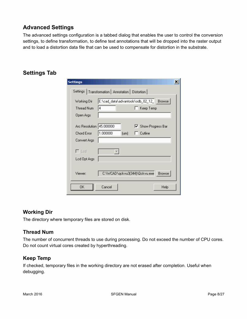
Settings Tab
Working DirThe directory where temporary files are stored on disk.
Thread NumThe number of concurrent threads to use during processing. Do not exceed the number of CPU cores.Do not count virtual cores created by hyperthreading.
Keep TempIf checked, temporary files in the working directory are not erased after completion. Useful when debugging.
March 2016 SFGEN Manual Page 8/27

Open ArgsSpecial arguments passed to the engine responsible for opening the input data. Only used for debugging.
Arc ResolutionWhen converting from ODB++ to GDSII this controls how arcs and circles are broken into segments. [See Reference]
Chord ErrorWhen converting from ODB++ to GDSII this controls how arcs and circles are broken into segments. [See Reference]
Show Progress BarIf checked, opens a window showing conversion progress. This may slow throughput slightly.
CutlineInstructs the program to use cut-lines instead of "butting" slices for polygons with islands. Do not use this option if you are also using the distortion function as it may result in illegal polygons in the output. This option is only present for testing purposes.
Convert ArgsCommand line arguments for the conversion engine are entered here. Normally this is left blank; the only time such arguments are needed is during testing and debugging.
ViewerEnter the path and executable of a GDSII viewer. When clicking the View Output button, SFGEN will call this program passing the name of the GDSII output file.
Example: c:\wcad\qckvu3\qckvu3.exe
March 2016 SFGEN Manual Page 9/27

Transformation Tab
DPIEnter the DPI that the RIP will use. This value (in conjunction with the buffer size) is used to determine the size of the repetitive geometries so that the RIP will have an optimum input.
Buffer Size
Enter the buffer size (this value is used in conjunction with the DPI) that the RIP will use to holdthe repetitive data. This is not the raster buffer size but a separate buffer dedicated to holding the bitmap masters.
Scale X
Enter the scale X factor and the anchor coordinate.
Scale Y
Enter the scale Y factor and the anchor coordinate.
Mirror X
Check to enable mirror X (i.e. X -> -X) also enter the anchor coordinate.
March 2016 SFGEN Manual Page 10/27

Mirror Y
Check to enable mirror Y (i.e. Y -> -Y) also enter the anchor coordinate.
Rotation
Enter a Rotation value in degrees (increasing angle is CCW) and an anchor point about which the input data is rotated.
Shift (X,Y)
Enter the offset along X and Y.
Offset (Edge Bias)
Select the offset mode: NONE, INNER, OUTER, BOTH. See the reference section for details as to how INNER, OUTER and BOTH are implemented.
Order of Transformation
The transformations are performed in the following order: 1 Scaling 2 Mirror X 3 Mirror Y 4 Rotation 5 Translation (Shift)
all units are in microns except rotation which is in degrees
March 2016 SFGEN Manual Page 11/27
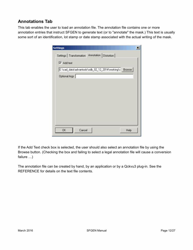
Annotations TabThis tab enables the user to load an annotation file. The annotation file contains one or more annotation entries that instruct SFGEN to generate text (or to "annotate" the mask.) This text is usuallysome sort of an identification, lot stamp or date stamp associated with the actual writing of the mask.
If the Add Text check box is selected, the user should also select an annotation file by using the Browse button. (Checking the box and failing to select a legal annotation file will cause a conversion failure …)
The annotation file can be created by hand, by an application or by a Qckvu3 plug-in. See the REFERENCE for details on the text file contents.
March 2016 SFGEN Manual Page 12/27

Distortion Tab
Distortion refers to a correction applied to the CAD data in order to warp the CAD data so that it "fits" on a substrate that may have been subject to some physical distortion due to either temperature or possibly processing (such as etching one side). Distortion can be corrected either in the SFGEN program or it can be corrected in the RTCR.
The correction works by reading the coordinates in a table of common points from both the CAD data and the measured on the substrate. These points drive a correction engine that attempts to match the distortion found on the substrate. Of course, there is no guarantee that the distortion can be exactly matched from only a relatively small number of data points.
See the reference section for details and examples.
Use Correction File
If checked, SFGEN will read the user specified correction file and apply corrections to the output file. Use the browse button to select the appropriate text file containing the coordinates.
Tolerance
A value (in microns) used to determine whether an instance of a cell is equivalent to other instances. Ifthis value is set too small, each bitmap placement will require its own definition and the RIP will not run very quickly. See the reference section on distortion to understand how the tolerance affects repetition and RIP throughput.
March 2016 SFGEN Manual Page 13/27

SFGEN Reference Section
TransformationsTransformations may be applied to the input data (ODB++ or GDSII)
Scale
Mirror
Rotation
Shift
Offset (Edge Bias)
Test DataFor purposes of illustrating each transformation we will use the test file shown below. The extents are 500,000 um X 610,000 um and the data is centered at 0,0. It consists of "frame boundaries" on layer 1and cells (1,2,3,4) with data on layer 2.
No transformations
March 2016 SFGEN Manual Page 14/27

ScalingScaling can be independently applied in both X and Y andthe anchor point for scaling can be specified by the user.In the example below a scale factor of 1.1 has beenapplied in X and 0.9 in Y with anchor at 0,0. In mostpractical cases, only very small scale factors are applied inorder to account for substrate expansion or contraction.
In the illustration at right, Xscale=1.1 and Yscale=0.9. Theextents of the image are now 550,000 x 549,000 um.
MirrorThe input data can be mirrored in X (about the Y axis), or mirrored in Y (about the X axis) or both. The position of the mirror line can be set.
MirrorX (about the Y axis at X=0)
March 2016 SFGEN Manual Page 15/27

Mirror Y (about the X axis at Y=0)
Mirror X and Mirror Y
March 2016 SFGEN Manual Page 16/27

RotationThe input data can be rotated around any user specified anchor point. Postive values rotate the data in the CCW direction.
Rotation about 0,0 of 10 degrees.
March 2016 SFGEN Manual Page 17/27

OffsetOffset, also known as edge bias, compensates for etch factor. There are two different modes.
At right you can see one of the geometries without any sizingapplied.
Both - if both is selected then the X and Ydirections are sized equally. The illustration atright shows the dimensions when a value of 5um has been applied in both X and Y.
XYBoth - Allows independent offset (edge bias) values for X and Y.In the example at right, the X offset = 10 um and the Y offset = 20um.
March 2016 SFGEN Manual Page 18/27
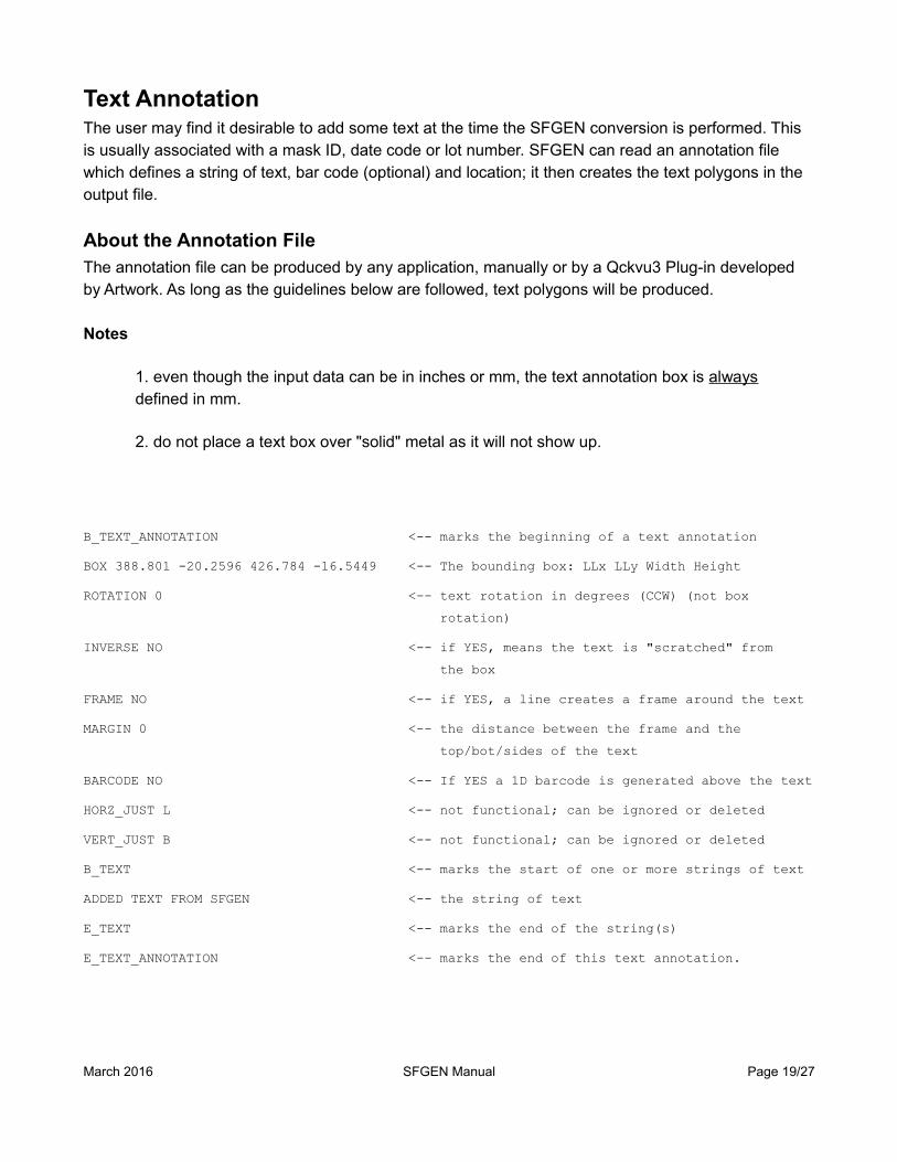
Text AnnotationThe user may find it desirable to add some text at the time the SFGEN conversion is performed. This is usually associated with a mask ID, date code or lot number. SFGEN can read an annotation file which defines a string of text, bar code (optional) and location; it then creates the text polygons in the output file.
About the Annotation FileThe annotation file can be produced by any application, manually or by a Qckvu3 Plug-in developed by Artwork. As long as the guidelines below are followed, text polygons will be produced.
Notes
1. even though the input data can be in inches or mm, the text annotation box is always defined in mm.
2. do not place a text box over "solid" metal as it will not show up.
B_TEXT_ANNOTATION <-- marks the beginning of a text annotation
BOX 388.801 -20.2596 426.784 -16.5449 <-- The bounding box: LLx LLy Width Height
ROTATION 0 <-- text rotation in degrees (CCW) (not box
rotation)
INVERSE NO <-- if YES, means the text is "scratched" from
the box
FRAME NO <-- if YES, a line creates a frame around the text
MARGIN 0 <-- the distance between the frame and the
top/bot/sides of the text
BARCODE NO <-- If YES a 1D barcode is generated above the text
HORZ_JUST L <-- not functional; can be ignored or deleted
VERT_JUST B <-- not functional; can be ignored or deleted
B_TEXT <-- marks the start of one or more strings of text
ADDED TEXT FROM SFGEN <-- the string of text
E_TEXT <-- marks the end of the string(s)
E_TEXT_ANNOTATION <-- marks the end of this text annotation.
March 2016 SFGEN Manual Page 19/27

Text Annotation Examples
Example 1
B_TEXT_ANNOTATIONBOX 32.2915 28.801 84.0326 35.9303ROTATION 0INVERSE NOFRAME NOMARGIN 0BARCODE NOB_TEXT226-01357-00E_TEXTE_TEXT_ANNOTATION
Example 2In example 2 we have two lines of text
B_TEXT_ANNOTATIONBOX 37.6661 29.9756 100.195 39.9916ROTATION 0INVERSE NOFRAME NOMARGIN 0BARCODE NOB_TEXT226-01357-00Revision AE_TEXTE_TEXT_ANNOTATION
March 2016 SFGEN Manual Page 20/27

Example 3In example 3 we typed a line of text and requested a bar code to go with it.
B_TEXT_ANNOTATIONBOX 37.6661 29.9756 100.195 39.9916ROTATION 0INVERSE NOFRAME NOMARGIN 0BARCODE YESB_TEXT226-01357-00E_TEXTE_TEXT_ANNOTATION
March 2016 SFGEN Manual Page 21/27

Distortion CorrectionDistortion Correction is used when imaging a substrate that has existing features on it and where the substrate may have stretched during processing or due to changes in the thermal environment. It is used to produce better alignment between the existing features and the ones being added by the imaging equipment.
We are going to use a ODB++ test file called p1.tgz to illustrate how distortion correction is performed.Let's look at the layout and start with 4 reference coordinates located in the corners of the panel.
If you zoom in on the corners you will see a small pad/drill hole (isolated from the ground plane so thatthe image acquisition system can find it and determine the precise coordinate.
March 2016 SFGEN Manual Page 22/27

We can use a CAD program to identify the CAD coordinates which are shown below:
When the panel is loaded onto the imaging machine, a camera finds the same four targets and measures the coordinates precisely. In a perfect world, the measured coordinates would match the CAD coordinates.
Let's assume that the panel is distorted slightly due to some temperature related expansion that occurred between drilling the holes and exposing the photo resist. Also, let's assume that because of the way the substrate is constructed, the expansion is not exactly the same in the X direction as the Y direction.
Let's further assume that for this example the board expands by .25% along X and by .45% along Y. (We will stipulate that the expansion can be computed by using the center of the board as the scaling anchor point). In that case we find that the measured corners are found at:
LL 59.2840, 3.6509UL 60.5572, 605.9491UR 492.3772, 605.9491LR 492.3772, 3.6509
March 2016 SFGEN Manual Page 23/27

Below you can see the movement due to expansion - where the CAD thinks the LL hole is located andwhere the camera system locates it.
Setting up the Correction Tablethe correction table requires that you enter the CAD coordinates followed by the delta to the measuredcoordinate. Further, it requires that the units be in microns. Therefore the table actually loaded into SFGEN will look like this:
59817, 5000, -533.0, -1349.161087, 604600, -529.8, 1349.1491830.1, 604600, 547.1, 1349.1491830.1, 5000, 547.1, -1349.1
This is the file that should be loaded into SFGEN to correct distortion due to anisotropic expansion of the panel material.
The output GDSII file will have its geometries shifted or modified in order to take into account the difference between the input CAD coordinates and the measured alignment marks. Therefore if the output file is used by an imaging machine the new features will closely align to the existing features over the full extents of the board.
March 2016 SFGEN Manual Page 24/27

SFGEN Command Line SyntaxThe SFGEN program can be run from the command line. This enables a user to create scripts to run multiple layers or to have custom settings for different layers.
Displaying the Syntax
To see the syntax and options type at a command prompt:
sfgen64.exe -h
Syntax Details
sfgen64.exe -job:<input_path> [OPT_ARGUMENTS]
where
sfgen64.exe name and path to the executable
input_path for GDSII input a path/name of a GDSII file for ODB++ input either a path to the top level of the ODB file hierarchy or a path/filename to a .tgz file
[OPT ARGUMENTS]
-outdir:<out_dir> for ODB++ input an output directory for GDSII input an output directory/file
-workdir:<working_dir> where temp files will be stored during conversion
-thrnum:<num_threads> max number of concurrent threads
-arcres:<res_dbl_value> arc resolution in degrees
-arcsag:<sag_dbl_value> arc sag (in um)
-cutline if specified gdsii islands are formed as cut lines if omitted, butting polygons are used
-gds_layer:<layer_int_value> output GDSII file layer
-gds_struct:<struct_name> output GDSII top structure name
March 2016 SFGEN Manual Page 25/27
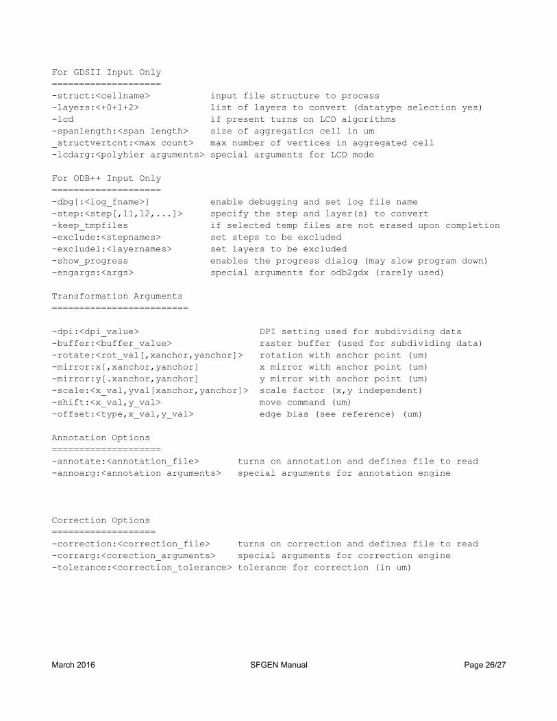
For GDSII Input Only====================-struct:<cellname> input file structure to process-layers:<+0+1+2> list of layers to convert (datatype selection yes)-lcd if present turns on LCD algorithms-spanlength:<span length> size of aggregation cell in um_structvertcnt:<max count> max number of vertices in aggregated cell-lcdarg:<polyhier arguments> special arguments for LCD mode
For ODB++ Input Only====================-dbg[:<log_fname>] enable debugging and set log file name-step:<step[,l1,l2,...]> specify the step and layer(s) to convert-keep_tmpfiles if selected temp files are not erased upon completion-exclude:<stepnames> set steps to be excluded-excludel:<layernames> set layers to be excluded-show_progress enables the progress dialog (may slow program down)-engargs:<args> special arguments for odb2gdx (rarely used)
Transformation Arguments=========================
-dpi:<dpi_value> DPI setting used for subdividing data-buffer:<buffer_value> raster buffer (used for subdividing data)-rotate:<rot_val[,xanchor,yanchor]> rotation with anchor point (um)-mirror:x[,xanchor,yanchor] x mirror with anchor point (um)-mirror:y[.xanchor,yanchor] y mirror with anchor point (um)-scale:<x_val,yval[xanchor,yanchor]> scale factor (x,y independent)-shift:<x_val,y_val> move command (um)-offset:<type,x_val,y_val> edge bias (see reference) (um)
Annotation Options====================-annotate:<annotation_file> turns on annotation and defines file to read-annoarg:<annotation arguments> special arguments for annotation engine
Correction Options===================-correction:<correction_file> turns on correction and defines file to read-corrarg:<corection_arguments> special arguments for correction engine-tolerance:<correction_tolerance> tolerance for correction (in um)
March 2016 SFGEN Manual Page 26/27

Command Line ExamplesAssume we have an ODB++ file called input.tgz and we want to create 4 GDSII files using the ODB++ layers: l1, l2p, l3p and l4. The ODB++ step to process is called panel. Our DPI is 5080. No correction or annotation. The command line could look like this: (I've put in returns to make it fit on the page …)
c:\wcad\sfgen64\sfgen64.exe -job:"E:\cad_files\input.tgz" -step:panel,l1 -outdir:"E:\cad_files\l1" -gds_layer:1 -gds_struct:TOP -workdir:"E:\cad_files\temp" -thrnum:4 -arcres:45 -arcscag:2 -dpi:5080 -buffer:2048 c:\wcad\sfgen64\sfgen64.exe -job:"E:\cad_files\input.tgz" -step:panel,l2p -outdir:"E:\cad_files\l2p" -gds_layer:1 -gds_struct:TOP -workdir:"E:\cad_files\temp" -thrnum:4 -arcres:45 -arcscag:2 -dpi:5080 -buffer:2048
c:\wcad\sfgen64\sfgen64.exe -job:"E:\cad_files\input.tgz" -step:panel,l3p -outdir:"E:\cad_files\l3p" -gds_layer:1 -gds_struct:TOP -workdir:"E:\cad_files\temp" -thrnum:4 -arcres:45 -arcscag:2 -dpi:5080 -buffer:2048
c:\wcad\sfgen64\sfgen64.exe -job:"E:\cad_files\input.tgz" -step:panel,l4 -outdir:"E:\cad_files\l4" -gds_layer:1 -gds_struct:TOP -workdir:"E:\cad_files\temp" -thrnum:4 -arcres:45 -arcscag:2 -dpi:5080 -buffer:2048
Each GDSII file would be in its own directory with data on GDSII layer 1 and a top structure named TOP.
March 2016 SFGEN Manual Page 27/27