user manual - timestone · color correction you can correct the color, density and contrast of an...
TRANSCRIPT
User Manual Updated for version 1.6
SOFTWARE LICENSE AGREEMENT IMPORTANT - READ CAREFULLY This is a legal agreement between you (either an individual or a single entity) and Timestone Software. By keeping this package and using the software, you are accepting the terms and are bound by the terms of this license. If you do not wish to enter into this agreement, please promptly return all copies of the Software, User Guides and Hardlock devices to Timestone Software for a full refund. This User Guide and the software programs it describes are protected by copyright, trade secret and trademark law. By accepting this license, you have the right to use them, subject to the terms and conditions of this license agreement.
Definitions and Interpretation
• Software means the Program modules enabled and authorised for use for your installation.
• Hardlock device means the hardware device used to enable the Software to function.
• Scope of Agreement
• Timestone Software hereby grants you, the original purchaser, personal, non-exclusive license to use the User Guide and the Software subject to the terms and conditions of this Agreement.
• Grant of License. You may use the Software on a maximum of one computer that you own or operate at a single physical location . You may transfer the Software from one computer to another provided that you do not use or permit the usage of the Software on more than one computer or computer terminal at a time.
• Copies. You may not copy or duplicate the Software, except as necessary solely for archival purposes, program error verification, or to replace defective storage media, provided you keep the original and the copies. You may not alter, decompile or disassemble the Software.
• Transfers. You may not sublicense, lease or rent or lend the Software or transfer any of your rights under this Agreement. You may transfer the Software (together with any backup copies you have made), Hardlock device and the User Guide on a permanent basis so long as you retain no copies, the transferee agrees to be bound by the terms of this Agreement, and Timestone Software has authorised the transfer by written confirmation.
• Term. The License granted in this agreement is effective until terminated. You may terminate it at any time by destroying or returning to Timestone Software the Software and the User Guide, together with all copies, and returning to Timestone Software the Hardlock Device. If you fail to comply with any term or condition of this Agreement, this License will terminate and, upon such termination, you agree to destroy or return to Timestone Software the Software and the User Guide, together with all copies, and return to Timestone Software the Hardlock Device. Termination of this license shall be in addition and not in lieu of any other remedies available to Timestone Software.
Limited Warranty, Disclaimer Timestone Software warrants that the media on which the Software is recorded and the User Guide provided with it are free from defects in material and workmanship under normal use for a period of 90 days from the date of your original purchase. Except for the limited warranty described above, the Software is sold “as is”, and you are assuming the entire risk as to its quality and performance. It is your responsibility to verify the results obtained from the use of the Software.
Limitation of Remedies If during the 90-day limited warranty period, you discover physical defects in the User Guide or in the Media on which the Software was recorded, Timestone Software will replace them as no charge to you. This is your sole remedy.
IN NO EVENT WILL TIMESTONE SOFTWARE BE LIABLE TO ANY PERSON FOR ANY DIRECT, INDIRECT, SPECIAL, INCIDENTAL, CONSEQUENTIAL OR SIMILAR DAMAGES, EVEN IF TIMESTONE SOFTWARE HAS BEEN ADVISED OF THE POSSIBILITY OF SUCH DAMAGES.

Table of Contents
1 – QuickStart NeoComposite.................................................................................................................. 1 Sample files .................................................................................................................................................................1 Getting to know NeoComposite...................................................................................................................................1 Details mode................................................................................................................................................................4 Match mode.................................................................................................................................................................5 Form Pages mode ........................................................................................................................................................6
2 – Before you Begin .............................................................................................................................. 11 Scope and audience ...................................................................................................................................................11 Pre-installation requirements.....................................................................................................................................11 Learning NeoComposite ............................................................................................................................................11 Getting help from Technical Support ........................................................................................................................12 Hardware requirements .............................................................................................................................................12
3 – Installation ........................................................................................................................................ 14 Installing the Adobe Acrobat Reader ........................................................................................................................15
4 – License Server .................................................................................................................................. 16 Understanding the License Server.............................................................................................................................16 Installing the License Server .....................................................................................................................................16 Configuring and testing the license server ................................................................................................................17 Enabling your licenses...............................................................................................................................................18 Configuring workstations to run................................................................................................................................19 Backing up your license server configuration ...........................................................................................................19
5 – Understanding NeoComposite ......................................................................................................... 20 NeoComposite templates ...........................................................................................................................................22 Production workflow.................................................................................................................................................24 Integration with other ‘Neo’ applications..................................................................................................................24 Using NeoComposite’s interface ...............................................................................................................................25 Using toolbars ...........................................................................................................................................................25 Resizing pane windows .............................................................................................................................................25 Opening, closing and maximizing panes...................................................................................................................25 Shortcut keys .............................................................................................................................................................26
6 – Configuring NeoComposite.............................................................................................................. 27 Setting the Program defaults .....................................................................................................................................27 Measurement units ....................................................................................................................................................27 Image Editor..............................................................................................................................................................27 Aspect ratios..............................................................................................................................................................28 Default Aspect Ratios................................................................................................................................................28 Default fields .............................................................................................................................................................30 Defining the Image file location................................................................................................................................32 Defining the Design File location..............................................................................................................................33 Monitor calibration....................................................................................................................................................33
7 – Job files ............................................................................................................................................. 34 Image import options.................................................................................................................................................34 Creating a new NeoComposite file ............................................................................................................................34 Specify the preview image size .................................................................................................................................34 Image importing types...............................................................................................................................................35 Original image file location.......................................................................................................................................35 Image numbering – indexed or sequential.................................................................................................................37 Image numbering.......................................................................................................................................................38 Specify the image file size.........................................................................................................................................38
8 – Details mode ..................................................................................................................................... 39 Entering Details mode ...............................................................................................................................................39 Creating a folder structure .........................................................................................................................................41 Importing name data..................................................................................................................................................41 Importing Shoot List data..........................................................................................................................................44 Editing the details and folders ...................................................................................................................................47 ‘Home’ folders and ‘attaching’ names ......................................................................................................................47 Exporting Details.......................................................................................................................................................48 Allocating File and Folder details .............................................................................................................................48 Labels ........................................................................................................................................................................50 Labeled Holders ........................................................................................................................................................50 Creating a Labeled Holder.........................................................................................................................................51
9 – Images mode ..................................................................................................................................... 54 Importing images.......................................................................................................................................................55 Import the images......................................................................................................................................................55 Configuring the import ..............................................................................................................................................55 Choose the files to import..........................................................................................................................................57 Specify the image import order .................................................................................................................................59 Using referenced-import job files..............................................................................................................................60 Other import sources .................................................................................................................................................61 Editing images while importing ................................................................................................................................62

Adding images...........................................................................................................................................................63 Deleting images.........................................................................................................................................................63 Closing and compacting files ....................................................................................................................................63 Correcting, editing and displaying images ................................................................................................................64 Image editing.............................................................................................................................................................64 Changing the number of images displayed................................................................................................................65 Correcting Images .....................................................................................................................................................66 Zooming and jogging in practice...............................................................................................................................67 Adjusting the image color, density and contrast........................................................................................................68 Exporting images.......................................................................................................................................................69
10 – Matching images and names ......................................................................................................... 71 Using Match mode ....................................................................................................................................................71 Matching – overview.................................................................................................................................................72 Matching from Shoot cards or order bags .................................................................................................................73 Match the images.......................................................................................................................................................74 Coping with errors.....................................................................................................................................................75 Adjusting a match......................................................................................................................................................76
11 – Design mode.................................................................................................................................... 80 Template types ..........................................................................................................................................................80 Template objects........................................................................................................................................................81 Using the template designer ......................................................................................................................................83 The designer toolbars ................................................................................................................................................83 Preparing and using graphic images..........................................................................................................................85 Merging images.........................................................................................................................................................87 Creating templates.....................................................................................................................................................88 Set the template page size..........................................................................................................................................89 Placing NeoComposite objects ..................................................................................................................................89 Placing objects...........................................................................................................................................................90 Placing graphic images..............................................................................................................................................92 Controlling image scaling..........................................................................................................................................97 Placing multiple objects in a Template......................................................................................................................99 Using text objects ....................................................................................................................................................101 Fixed and variable text ............................................................................................................................................101 Variable text objects................................................................................................................................................103 Using barcode objects .............................................................................................................................................108 Labeled Holders ......................................................................................................................................................109 Cut marks ................................................................................................................................................................110 Defining Hole Punches............................................................................................................................................112 Saving templates .....................................................................................................................................................112 Creating templates...................................................................................................................................................113 Creating a Simple page layout.................................................................................................................................113

Creating a simple multi-page composite .................................................................................................................117 Creating ‘protected’ pages.......................................................................................................................................121 Create a ‘Rotated’ page ...........................................................................................................................................124 Create a simple rotated template .............................................................................................................................125 Create a page with separate Rotated and Static versions.........................................................................................127 Subject blocks .........................................................................................................................................................129 Subject block components.......................................................................................................................................129 Creating a Subject Block template ..........................................................................................................................129 Board blocks............................................................................................................................................................136 Create a board..........................................................................................................................................................136 Advanced graphic effects ........................................................................................................................................140 Apply a simple mask ...............................................................................................................................................140
12 – Forming Pages .............................................................................................................................. 141 Form Page interface.................................................................................................................................................141 Create a new Composite page .................................................................................................................................142 Rotated pages ..........................................................................................................................................................146
13 – Printing ......................................................................................................................................... 148 Select the Groups.....................................................................................................................................................148 Selecting the printer.................................................................................................................................................149 Choose the Print method .........................................................................................................................................149 Printing to a standard Windows printer driver ........................................................................................................152 Automatic paper size selection................................................................................................................................153 Alignment and Cut marks........................................................................................................................................154
14 – Calibration & Color Management ............................................................................................. 156
Index...................................................................................................................................................... 157

1 – Qu
NeoCompos
1
ickStart NeoCompositeThis guide is a quick-start for those wanting to become quickly acquainted with NeoComposite. This guide assumes that the application has been successfully installed, and that you are familiar with Microsoft Windows applications.
Sample files The NeoComposite installer places several sample files and images into the \Program Files\Timestone Software\ directory. These directories are:
\Program Files\Timestone Software\Example Files Contains a sample NeoComposite job file.
\Program Files\Timestone Software\Sample Images Contains sample images required by the sample job file and the tutorial.
\Program Files\Timestone Software\Templates\NeoComposite Contains sample templates.
! The file does not include the original high resolution images, and so you will not be able to print any pages from the example file. The example file is intended only to give a quick overview of NeoComposite’s features.
Getting to know NeoComposite
Open the sample file Start NeoComposite by choosing Start > Program Files > Timestone Software > NeoComposite. NeoComposite launches.
Choose File > Open. Navigate to the \Program Files\Timestone Software\Example Files directory, and open the file, Composite(Demo).tnj. The sample file opens.
Modes
ite – Chapter 1 – QuickStart Page 1

There are 5 modes of operation:
Details mode – import and edit job name and other details information
#
#
#
#
#
Images mode – import crop and color correct the portrait images Match mode – match images to names Form Pages mode – form the finished composite pages Design mode – create the templates to be used for the pages
Switch between the modes by choosing the Mode menu, then the mode you want. Note the shortcuts for switching modes.
Images mode Images mode is used to import and prepare images for use in NeoComposite pages. Several controls let you change the number of images displayed on the screen at once.
Single Image mode Click the Single Image mode button. The display changes to show one single image.
Multi Image mode Click the Multiple Image mode button. The display changes to show multiple images on-screen.
NeoComposite – Chapter 1 – QuickStart Page 2

Change the number of images displayed You can control the number of images displayed using the Images button. Click the button, then pull the grid that opens to select the number of images you want. Click the mouse and the screen re-draws for the selected number of images.
Cropping Images Switch to Single Image mode, then click the image displayed. Note that it highlights darker grey. Switch to Image Crop mode by clicking the Crop button in the toolbar. Note that several lines now appear over the portrait image. These lines indicate 2 aspect ratios, 2:3 and 4:5.
Click the image and drag the mouse whilst still holding down the mouse button. The image will move on-screen. You can also hold the Ctrl down, then the Arrow keys to crop the image.
To reset the position of the image, click the Reset crop button in the Crop sidebar. Now, hold the Shift key down on the keyboard and move the mouse up and down in a vertical
NeoComposite – Chapter 1 – QuickStart Page 3
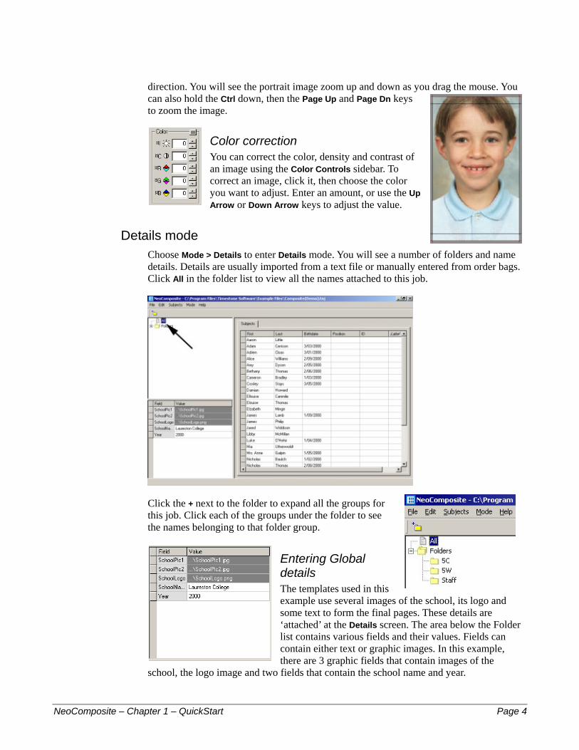
direction. You will see the portrait image zoom up and down as you drag the mouse. You can also hold the Ctrl down, then the Page Up and Page Dn keys to zoom the image.
Color correction You can correct the color, density and contrast of an image using the Color Controls sidebar. To correct an image, click it, then choose the color you want to adjust. Enter an amount, or use the Up Arrow or Down Arrow keys to adjust the value.
Details mode Choose Mode > Details to enter Details mode. You will see a number of folders and name details. Details are usually imported from a text file or manually entered from order bags. Click All in the folder list to view all the names attached to this job.
Click the + next to the folder to expand all the groups for this job. Click each of the groups under the folder to see the names belonging to that folder group.
Entering Global details The templates used in this example use several images of the school, its logo and some text to form the final pages. These details are ‘attached’ at the Details screen. The area below the Folder list contains various fields and their values. Fields can contain either text or graphic images. In this example, there are 3 graphic fields that contain images of the
school, the logo image and two fields that contain the school name and year.
NeoComposite – Chapter 1 – QuickStart Page 4
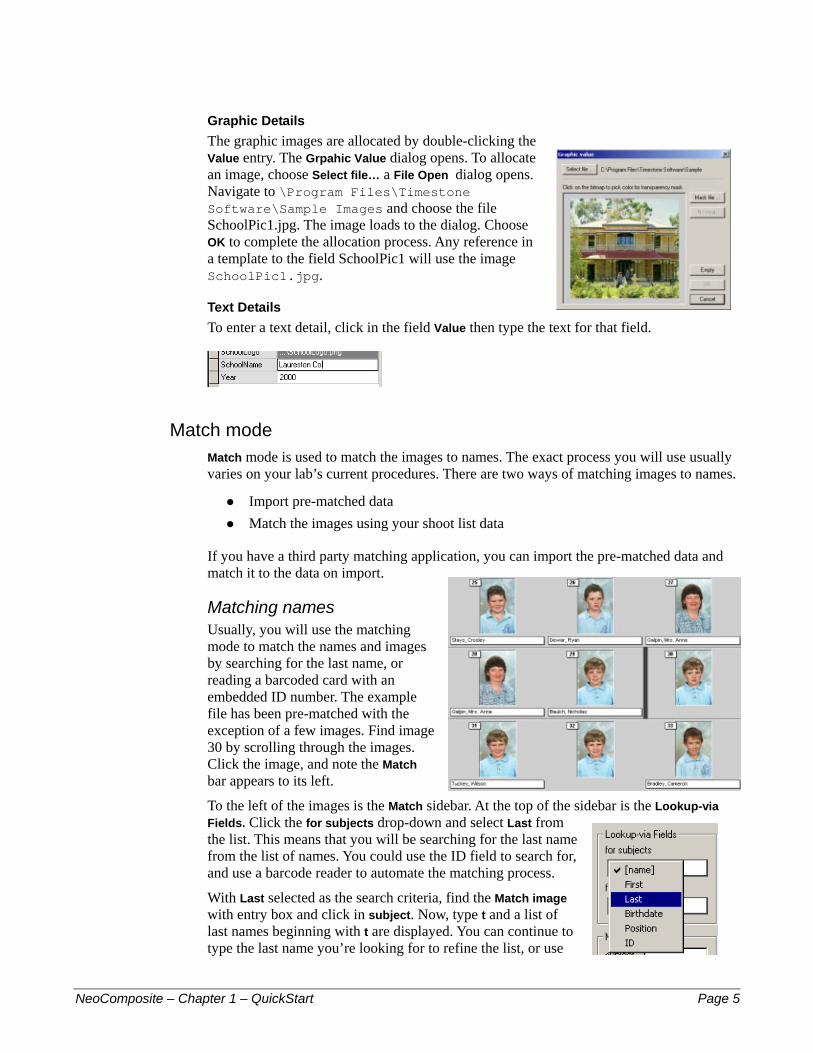
Graphic Details The graphic images are allocated by double-clicking the Value entry. The Grpahic Value dialog opens. To allocate an image, choose Select file… a File Open dialog opens. Navigate to \Program Files\Timestone Software\Sample Images and choose the file SchoolPic1.jpg. The image loads to the dialog. Choose OK to complete the allocation process. Any reference in a template to the field SchoolPic1 will use the image SchoolPic1.jpg.
Text Details To enter a text detail, click in the field Value then type the text for that field.
Match mode Match mode is used to match the images to names. The exact process you will use usually varies on your lab’s current procedures. There are two ways of matching images to names.
Import pre-matched data #
# Match the images using your shoot list data
If you have a third party matching application, you can import the pre-matched data and match it to the data on import.
Matching names Usually, you will use the matching mode to match the names and images by searching for the last name, or reading a barcoded card with an embedded ID number. The example file has been pre-matched with the exception of a few images. Find image 30 by scrolling through the images. Click the image, and note the Match bar appears to its left.
To the left of the images is the Match sidebar. At the top of the sidebar is the Lookup-via Fields. Click the for subjects drop-down and select Last from the list. This means that you will be searching for the last name from the list of names. You could use the ID field to search for, and use a barcode reader to automate the matching process.
With Last selected as the search criteria, find the Match image with entry box and click in subject. Now, type t and a list of last names beginning with t are displayed. You can continue to type the last name you’re looking for to refine the list, or use
NeoComposite – Chapter 1 – QuickStart Page 5
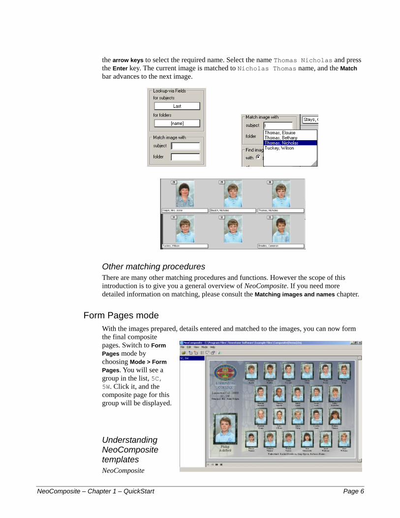
the arrow keys to select the required name. Select the name Thomas Nicholas and press the Enter key. The current image is matched to Nicholas Thomas name, and the Match bar advances to the next image.
Other matching procedures There are many other matching procedures and functions. However the scope of this introduction is to give you a general overview of NeoComposite. If you need more detailed information on matching, please consult the Matching images and names chapter.
Form Pages mode With the images prepared, details entered and matched to the images, you can now form the final composite pages. Switch to Form Pages mode by choosing Mode > Form Pages. You will see a group in the list, 5C, 5W. Click it, and the composite page for this group will be displayed.
Understanding NeoComposite templates
NeoComposite – Chapter 1 – QuickStart Page 6
NeoComposite

templates consist of three separate templates:
Page template – the overall page layout #
#
#
Subject block – each portrait design Board block – the Board design (if used)
Each page must have a Page and Subject template selected, but the Board is optional and is not required to complete the page.
Understanding NeoComposite groups When forming a NeoComposite page, you choose the groups to include, the sorting order then the templates to use. NeoComposite then forms the pages as determined by the templates selected.
Adding a composite page The first step when creating a new composite page is to add a composite page to the list. Click the Add Page button in the toolbar and the Subjects to include dialog opens.
Choosing the subjects to include The subjects that will appear on the composite page are selected in the Subjects to Include dialog. Choose the groups you want to include, and note the list of names fills as you select a group. Individual names can be switched on and off for each page by checking the Include tick in the list. Choose OK and note that a new page is added to the list of pages.
NeoComposite – Chapter 1 – QuickStart Page 7
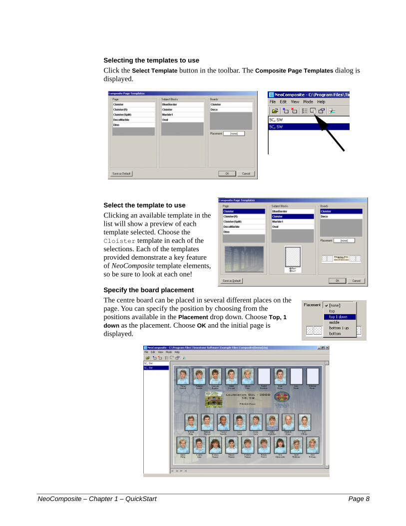
Selecting the templates to use Click the Select Template button in the toolbar. The Composite Page Templates dialog is displayed.
Select the template to use Clicking an available template in the list will show a preview of each template selected. Choose the Cloister template in each of the selections. Each of the templates provided demonstrate a key feature of NeoComposite template elements, so be sure to look at each one!
Specify the board placement The centre board can be placed in several different places on the page. You can specify the position by choosing from the positions available in the Placement drop down. Choose Top, 1 down as the placement. Choose OK and the initial page is displayed.
NeoComposite – Chapter 1 – QuickStart Page 8
Specify the sort and unfeatured handling You’ll notice there are several un-matched (missing portrait) images on this initial page. This is because there are several names included in the group that don’t have matched portraits. Perhaps they were absent on photography day.
Also, the group is sorted alphabetically with no special sorting for the group. You can specify three sort levels and so sort the images into group order, alphabetically. To do this, choose the Composite page options button in the toolbar. The Composite page options dialog opens.
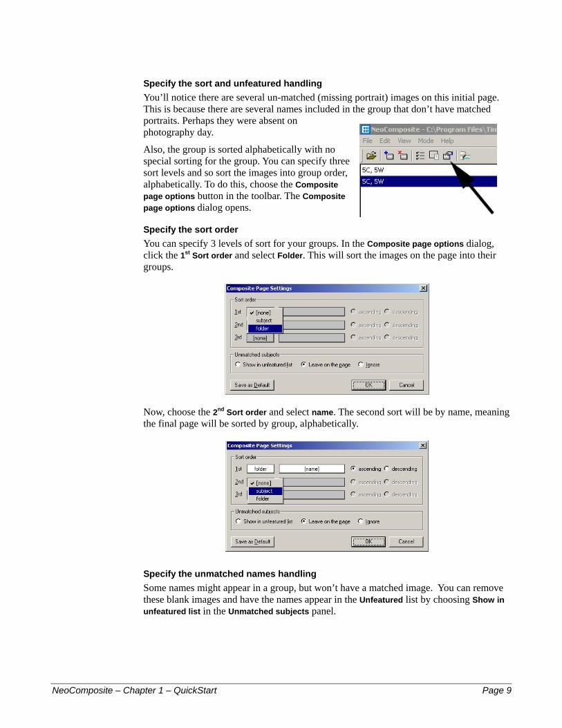
Specify the sort order You can specify 3 levels of sort for your groups. In the Composite page options dialog, click the 1st Sort order and select Folder. This will sort the images on the page into their groups.
Now, choose the 2nd Sort order and select name. The second sort will be by name, meaning the final page will be sorted by group, alphabetically.
Specify the unmatched names handling Some names might appear in a group, but won’t have a matched image. You can remove these blank images and have the names appear in the Unfeatured list by choosing Show in unfeatured list in the Unmatched subjects panel.
NeoComposite – Chapter 1 – QuickStart Page 9
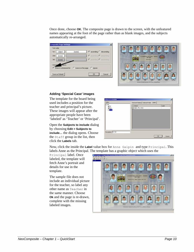
Once done, choose OK. The composite page is drawn to the screen, with the unfeatured names appearing at the foot of the page rather than as blank images, and the subjects automatically re-arranged.
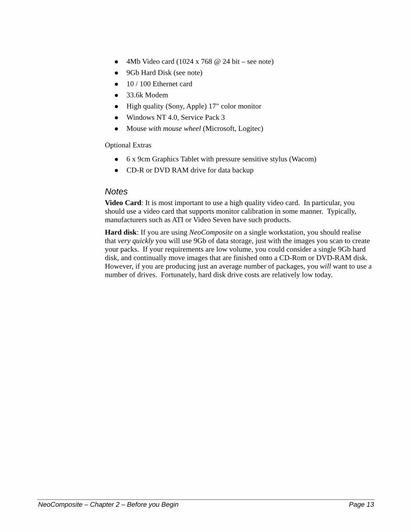
Adding ‘Special Case’ images The template for the board being used includes a position for the teacher and principal’s picture. These images will appear after the appropriate people have been ‘labeled’ as ‘Teacher’ or ‘Principal’.
Open the Subjects to include dialog by choosing Edit > Subjects to include… the dialog opens. Choose the Staff group in the list, then click the Labels tab.
Now, click the inside the Label value box for Anne Galpin and type Principal. This labels Anne as the Principal. The template has a graphic object which uses the Principal label. Once labeled, the template will fetch Anne’s portrait and details for use in the template.
The sample file does not include an individual picture for the teacher, so label any other name as Teacher in the same manner. Choose Ok and the page is re-drawn, complete with the missing labeled images.
NeoComposite – Chapter 1 – QuickStart Page 10

2 – Be
NeoCompos
22
fore you BeginScope and audience This manual covers both operation and technical aspects required to use NeoComposite. The manual is divided into several chapters – see the Table of Contents at the start for a broad sweep. Alternatively, consult the Index for specific procedures.
If you’re planning to have multiple users using NeoComposite in a networked environment, you’ll need to look at Chapter 4, License Server, for info on how the license system works and where to put that hardlock/dongle we sent you!
Getting more help More help is available for NeoComposite from the following places:
Related documents such as our Color Management Guide and the Bitmap Compare Utility Guide.
#
#
#
#
#
#
#
#
#
Help pages from our WWW site, http://www.timestone.com.au Technical support as noted at the end of this chapter
Pre-installation requirements You will need to following resources and information before you start installing NeoComposite:
NeoComposite software installation CD-ROM NeoComposite software User Manual (you’re reading it) Hardware protection device (a ‘hardlock’ or ‘dongle’) ‘Unlock’ code supplied by Timestone Software Your computer complies with the hardware and software specifications as outlined in Chapter 3, Installation.
Learning NeoComposite Included on the NeoComposite CD-ROM are contained the following resources:
ite – Chapter 2 – Before you Begin Page 11
Installation files

NeoComposite User Manual – the document you are currently reading #
#
#
#
#
#
#
#
Getting help from Technical Support We offer many different methods of support. However, we strongly encourage you to use e-mail as your primary support mechanism.
Telephone support
!
☎ Telephone support is available by calling Timestone Software during our business hours. These hours are:
9:00 AM – 5:00 PM Australian Eastern time
The telephone numbers is:
Voice: + 61 3 9570 9899
Fax support You can fax us with questions or queries. Please address your fax queries to Technical Support. The fax number is:
Fax: + 61 3 9570 9855
E-mail and WWW support There are support pages that include links to the newest versions of the software, as well as user documentation, and ‘Frequently Asked Questions’.
Our WWW and e-mail contacts are:
WWW: http://www.timestone.com.au E-mail: [email protected]
Hardware requirements The following hardware requirements are required as a minimum configuration to run NeoComposite. You should always attempt to exceed these requirements.
If you have a choice in areas in which you can afford to exceed these requirements, do so in the following order:
Memory CPU class (Pentium II, Pentium III) and clock speed Hard disk speed (Ultra, Ultra Wide, RAID) Other
Minimum requirements Intel Pentium II processor at 350 Mhz 100 Mhz system motherboard (Bx class) 128 Mb RAM
NeoComposite – Chapter 2 – Before you Begin Page 12
4Mb Video card (1024 x 768 @ 24 bit – see note) #
#
#
#
#
#
#
#
#
9Gb Hard Disk (see note) 10 / 100 Ethernet card 33.6k Modem High quality (Sony, Apple) 17" color monitor Windows NT 4.0, Service Pack 3 Mouse with mouse wheel (Microsoft, Logitec)
Optional Extras
6 x 9cm Graphics Tablet with pressure sensitive stylus (Wacom) CD-R or DVD RAM drive for data backup
Notes Video Card: It is most important to use a high quality video card. In particular, you should use a video card that supports monitor calibration in some manner. Typically, manufacturers such as ATI or Video Seven have such products.
Hard disk: If you are using NeoComposite on a single workstation, you should realise that very quickly you will use 9Gb of data storage, just with the images you scan to create your packs. If your requirements are low volume, you could consider a single 9Gb hard disk, and continually move images that are finished onto a CD-Rom or DVD-RAM disk. However, if you are producing just an average number of packages, you will want to use a number of drives. Fortunately, hard disk drive costs are relatively low today.
NeoComposite – Chapter 2 – Before you Begin Page 13

3 – Ins
NeoCompos
3
tallationOpen the CD-Rom in Windows Explorer or My Computer, and double-click the file, Install NeoComposite. The installer screen appears.
The installation process may require a restart before completion. If the installer requests you to restart the PC, please do so.
• Choose Next to proceed.
• Note the contents of the ReadMe screen. It contains information that may be required for the installation. Choose Next to proceed.
• Choose the location for the program files to be installed to. Unless you have a particular reason for changing the default path setting, we recommend you leave it as is. Choose Next to proceed.
• Allow the program to create backup files for the installation. Choose Next to proceed.
• Choose the components to install. If this machine is to host the hardlock, install the License Server component.
• Documentation and tutorial files are installed to the same directory as the program files.
ite – Chapter 3 – Installation Page 14
• Choose Next to proceed.
• Select the name of the Program Manager group to add the icons to. Choose Next to proceed.
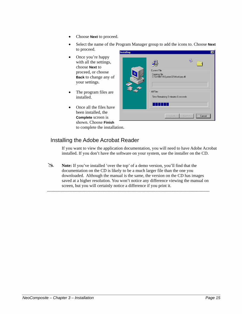
• Once you’re happy with all the settings, choose Next to proceed, or choose Back to change any of your settings.
• The program files are installed.
• Once all the files have been installed, the Complete screen is shown. Choose Finish to complete the installation.
Installing the Adobe Acrobat Reader If you want to view the application documentation, you will need to have Adobe Acrobat installed. If you don’t have the software on your system, use the installer on the CD.
! Note: If you’ve installed ‘over the top’ of a demo version, you’ll find that the documentation on the CD is likely to be a much larger file than the one you downloaded. Although the manual is the same, the version on the CD has images saved at a higher resolution. You won’t notice any difference viewing the manual on screen, but you will certainly notice a difference if you print it.
NeoComposite – Chapter 3 – Installation Page 15

4 – Lic
NeoCompos
4
ense ServerTimestone Software’s Neo applications are protected from unauthorised use by a license server. The license server runs as a Windows NT service, and is installed as a component of the installer. It consists of several components:
A hardlock or dongle that is connected to the Server PC’s Parallel port #
#
#
#
!
The License server, installed only to the server PC The License Manager which is installed to the Server, or can be used on a workstation connected to the network Several support files
Understanding the License Server When a Neo application is licensed from Timestone Software, we issue your site with a hardlock or dongle. This hardlock contains a unique Key code that is specific to your installation. Without the hardlock, it is not possible to use the Neo application.
It is possible to purchase single or multi-user licenses for Neo applications. When the license is issued, it is ‘added’ to the license server. You are then able to use the number of applications you have licenses for.
When a Neo application is started, it asks the License Server if there is a license available to use. If there is, the application will launch and ‘use’ a license.
If there are insufficient licenses available for that application, an error message will be given and the program will quit. You will not be able to launch the application until a license becomes available, either by adding more licenses, or by waiting until one of the users quits their Neo application session.
Installing the License Server When installing the Neo application, choose the License Server component. The License Server service will be installed.
It is not necessary to install the License Server on any machine other than the one that will host the hardlock.
ite – Chapter 4 – License Server Page 16

You will be required to re-start the PC. Do so.
Once the PC has been re-started, you will notice several things:
A new control panel License Server has been added to the Windows Control Panel
#
#
#
#
#
#
#
A new service, Timestone License Server has been added to the Services list A new program, License Manager has been added to the Start, Timestone Software menu.
Configuring and testing the license server The hardlock can be connected to the parallel port of any machine on the local area network. This machine doesn’t have to have a Neo application installed to act as a hardlock server, but the workstations that do have Neo applications installed must be able to ‘see’ the machine that has the hardlock.
Hardlock and License Server installation First, make sure the hardlock is plugged into the hardlock server’s parallel port. Run the Neo application installer, and make sure that the License Server and Support Files components are chosen. It is not necessary to choose the Neo application component if this machine will not run the application. Allow the installer to re-start the PC as required.
License Server configuration Open the Windows Control Panel. Locate the License Server icon, and double-click it. The License Server control panel opens.
Enter the computer name for the hardlock server, and press Test. The License Server will then check to confirm the presence of the hardlock on the PC. If the hardlock is correctly detected, the control panel will report OK. If an error is displayed, confirm the following:
Check you have entered the computer’s name correctly The hardlock is connected to the PC’s Parallel port The parallel port is functioning correctly Both the License Server and Support Files components have been installed
If an error is still given, contact Timestone Software or your distributor for support.
NeoComposite – Chapter 4 – License Server Page 17
Enabling your licenses When you purchase a Neo application, you will receive a number of user licenses. Timestone Software will supply a number of enable codes that will add licenses to the license server. These files are supplied either as an e-mail to your system administrator, or on a CD-Rom. The enable codes are shipped to you separate from the hardlock for security reasons.
Adding the licenses to the license server Ensure that the hardlock and server software has been installed and successfully configured.
From the Start menu, choose, Timestone Software > License Manager. The License Manager will open.
Pay particular attention to any errors displayed in the Last Error section. Before any configuration has been carried out, it may display Missing/empty license code table file. This error will disappear once valid licenses have been installed. If the error reads Hardlock is invalid or missing, review the installation of the hardlock and License Server.
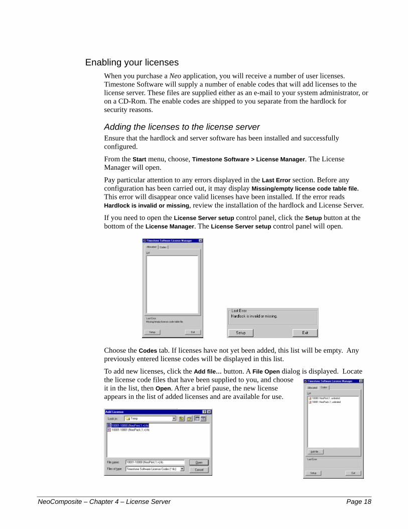
If you need to open the License Server setup control panel, click the Setup button at the bottom of the License Manager. The License Server setup control panel will open.
Choose the Codes tab. If licenses have not yet been added, this list will be empty. Any previously entered license codes will be displayed in this list.
To add new licenses, click the Add file… button. A File Open dialog is displayed. Locate the license code files that have been supplied to you, and choose it in the list, then Open. After a brief pause, the new license appears in the list of added licenses and are available for use.
NeoComposite – Chapter 4 – License Server Page 18
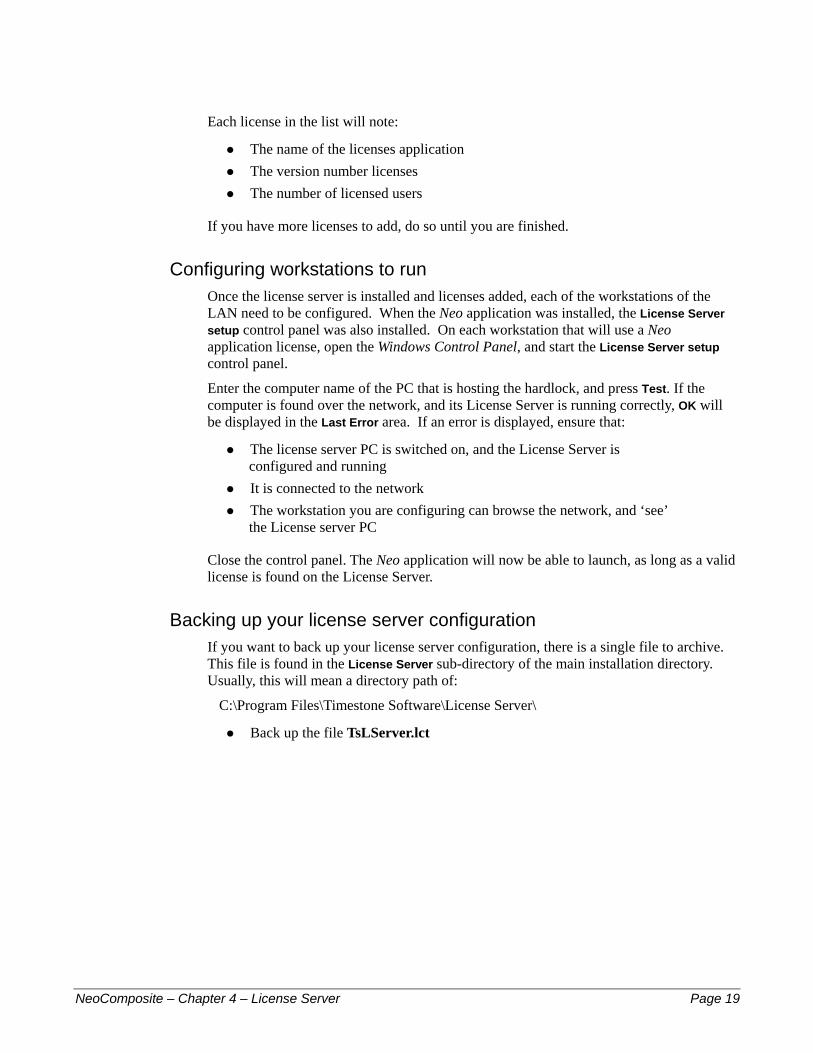
Each license in the list will note:
The name of the licenses application #
#
#
#
#
#
#
The version number licenses The number of licensed users
If you have more licenses to add, do so until you are finished.
Configuring workstations to run Once the license server is installed and licenses added, each of the workstations of the LAN need to be configured. When the Neo application was installed, the License Server setup control panel was also installed. On each workstation that will use a Neo application license, open the Windows Control Panel, and start the License Server setup control panel.
Enter the computer name of the PC that is hosting the hardlock, and press Test. If the computer is found over the network, and its License Server is running correctly, OK will be displayed in the Last Error area. If an error is displayed, ensure that:
The license server PC is switched on, and the License Server is configured and running It is connected to the network The workstation you are configuring can browse the network, and ‘see’ the License server PC
Close the control panel. The Neo application will now be able to launch, as long as a valid license is found on the License Server.
Backing up your license server configuration If you want to back up your license server configuration, there is a single file to archive. This file is found in the License Server sub-directory of the main installation directory. Usually, this will mean a directory path of:
C:\Program Files\Timestone Software\License Server\
Back up the file TsLServer.lct
NeoComposite – Chapter 4 – License Server Page 19
5 – Un
NeoCompos
5
derstanding NeoCompositeNeoComposite is a comprehensive production environment for creating page composites. It has several different modes of operation that focus on the various production tasks required to create the pages. These modes are:
Details mode – import , edit and allocate various attributes to subject names
#
#
#
#
#
#
#
#
#
#
Images mode – import, crop and color correct images Match mode – match images to names Form Pages mode – create the finished composite pages Design mode – create the templates for use with the finished pages
The use of the various modes lets you spread the production tasks amongst your staff. Staff used to using spreadsheets and handling data prepare the subject data in Details mode. Your skilled graphic designers create the templates in Adobe Photoshop, then compile the elements into a NeoComposite template. Your lab production staff handle the images and finally compile and print the jobs.
Because NeoComposite divides the production tasks into distinct categories, the workflow is clearly divided into 3 main tasks:
Creating the templates Creating the job files, importing or entering the name data and allocating referenced objects (such as the logo) Importing and preparing images, creating the composite pages and printing
Details mode NeoComposite uses an integrated Details editor to import group, name and other job specific information. Groups are divided into a series of folders that contain the name and other information required for each individual in a group.
Fields are easily defined and customised to match your production needs, and fall into several categories:
File fields – job-specific information, such as a school name or logo Folder fields – group-specific information, such as a class mascot etc.
ite – Chapter 5 – Understanding NeoComposite Page 20
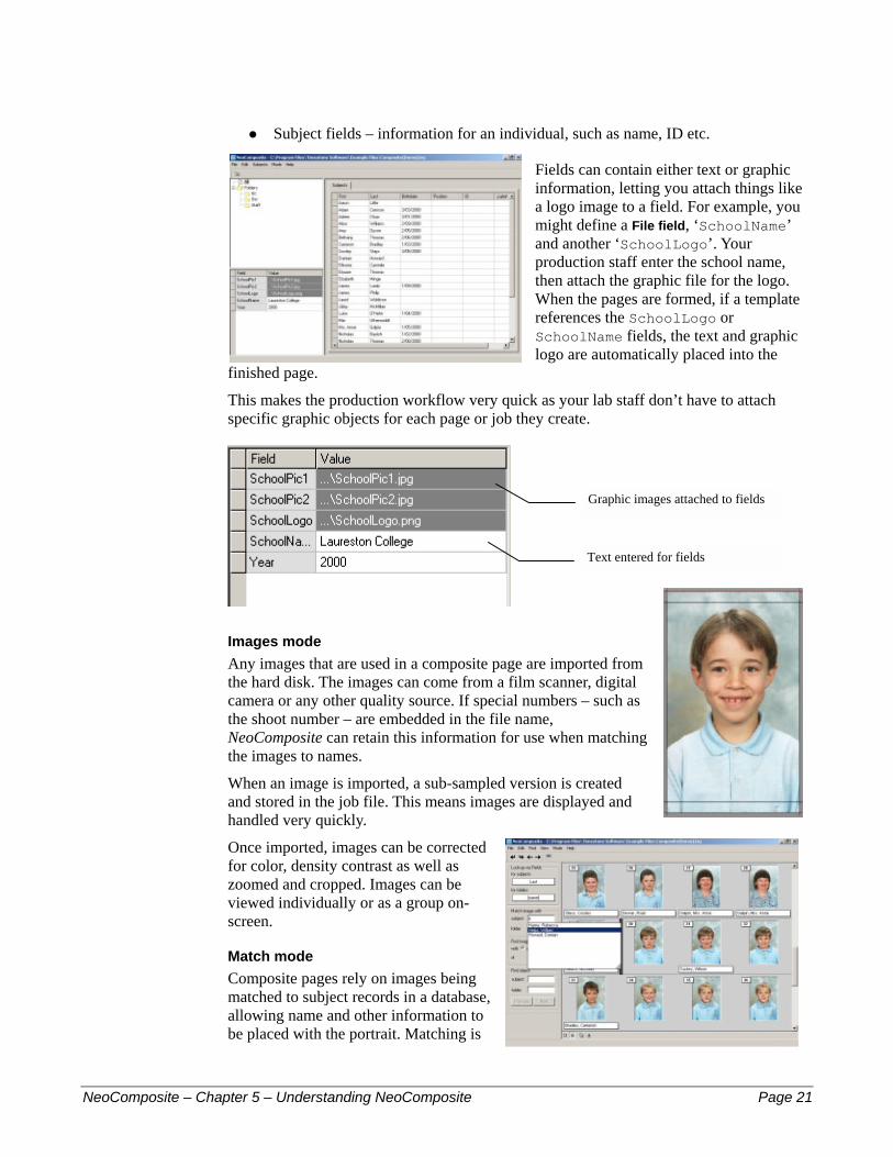
Subject fields – information for an individual, such as name, ID etc. #
Fields can contain either text or graphic information, letting you attach things like a logo image to a field. For example, you might define a File field, ‘SchoolName’ and another ‘SchoolLogo’. Your production staff enter the school name, then attach the graphic file for the logo. When the pages are formed, if a template references the SchoolLogo or SchoolName fields, the text and graphic logo are automatically placed into the
finished page.
This makes the production workflow very quick as your lab staff don’t have to attach specific graphic objects for each page or job they create.
Graphic images attached to fields
Text entered for fields
Images mode Any images that are used in a composite page are imported from the hard disk. The images can come from a film scanner, digital camera or any other quality source. If special numbers – such as the shoot number – are embedded in the file name, NeoComposite can retain this information for use when matching the images to names.
When an image is imported, a sub-sampled version is created and stored in the job file. This means images are displayed and handled very quickly.
Once imported, images can be corrected for color, density contrast as well as zoomed and cropped. Images can be viewed individually or as a group on-screen.
Match mode Composite pages rely on images being matched to subject records in a database, allowing name and other information to be placed with the portrait. Matching is
NeoComposite – Chapter 5 – Understanding NeoComposite Page 21

the process of joining all the images from the group – which are in shoot order – to the names entered in the database.
Your lab will most likely have a process that gathers this information, and NeoComposite has many tools that let you continue to use or enhance the process. Fundamentally, on photography day, you will have some method of creating a shoot list. This list is the order in which each student was photographed and how many times. Back in the lab, the shoot list is matched to the digital images in the matching process.
NeoComposite’s matching process is highly visual, and so is easily understood by your operators.
Template based production NeoComposite uses templates extensively to form the composite pages. Your graphic design staff create the templates that contain references to graphic and text objects such as the school’s logo and name, principal’s portrait and name etc. During the production process, these elements are added to the database for the school. When a template that calls for the elements is used, NeoComposite automatically fetches the graphic or text and places it automatically into the design.
This means that creating the pages is a simple matter of choosing the groups to use, the sort order and template to use.
NeoComposite templates NeoComposite templates are a powerful combination of graphic, text and various replaceable objects. The templates are created with the integrated template editor by placing and positioning the various elements. The template editor itself has no creation tools, meaning that it must be used in conjunction with an image editor such as Adobe Photoshop or Corel Draw.
There are 3 types of template:
Page Layout –the size and overall look of the finished page #
#
#
#
Subject blocks – how each portrait appears, including the name text, portrait border and masks Board blocks – the look of the (optional) centre board
Page Layouts A Page Layout template determines the overall size and look of the completed composite page. It contains a variety of graphic, text and other NeoComposite specific objects that complete the finished design. There are several types of objects that can be placed into a page layout:
Page size – determines the final size of the finished page
NeoComposite – Chapter 5 – Understanding NeoComposite Page 22
Fixed text or graphics – text or graphic images that will not change for the whole production, such as a background image
#
#
#
Variable text or graphics – text or graphic images that will change according to the job or individual (school logo, special position like ‘Class Captain’) NeoComposite specific objects – objects that define things like the portrait position etc.
Page size
Variable graphic object
NeoComposite specific objects
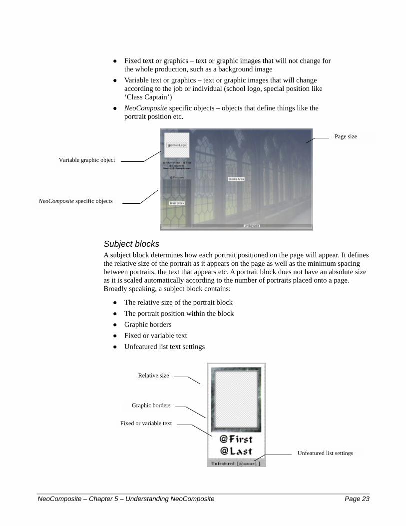
Subject blocks A subject block determines how each portrait positioned on the page will appear. It defines the relative size of the portrait as it appears on the page as well as the minimum spacing between portraits, the text that appears etc. A portrait block does not have an absolute size as it is scaled automatically according to the number of portraits placed onto a page. Broadly speaking, a subject block contains:
The relative size of the portrait block #
#
#
#
#
The portrait position within the block Graphic borders Fixed or variable text Unfeatured list text settings
Relative size
Graphic borders
Fixed or variable text
Unfeatured list settings
NeoComposite – Chapter 5 – Understanding NeoComposite Page 23
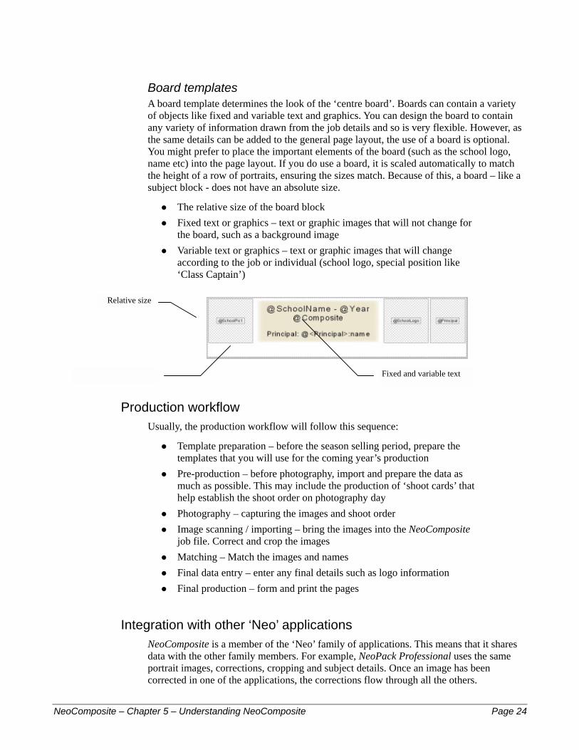
Board templates A board template determines the look of the ‘centre board’. Boards can contain a variety of objects like fixed and variable text and graphics. You can design the board to contain any variety of information drawn from the job details and so is very flexible. However, as the same details can be added to the general page layout, the use of a board is optional. You might prefer to place the important elements of the board (such as the school logo, name etc) into the page layout. If you do use a board, it is scaled automatically to match the height of a row of portraits, ensuring the sizes match. Because of this, a board – like a subject block - does not have an absolute size.
The relative size of the board block #
#
#
Fixed text or graphics – text or graphic images that will not change for the board, such as a background image Variable text or graphics – text or graphic images that will change according to the job or individual (school logo, special position like ‘Class Captain’)
Relative size
Variable graphic object Fixed and variable text
Production workflow Usually, the production workflow will follow this sequence:
Template preparation – before the season selling period, prepare the templates that you will use for the coming year’s production
#
#
#
#
#
#
#
Pre-production – before photography, import and prepare the data as much as possible. This may include the production of ‘shoot cards’ that help establish the shoot order on photography day Photography – capturing the images and shoot order Image scanning / importing – bring the images into the NeoComposite job file. Correct and crop the images Matching – Match the images and names Final data entry – enter any final details such as logo information Final production – form and print the pages
Integration with other ‘Neo’ applications NeoComposite is a member of the ‘Neo’ family of applications. This means that it shares data with the other family members. For example, NeoPack Professional uses the same portrait images, corrections, cropping and subject details. Once an image has been corrected in one of the applications, the corrections flow through all the others.
NeoComposite – Chapter 5 – Understanding NeoComposite Page 24
Using NeoComposite’s interface Once NeoComposite has been installed, choose Start menu > Program Files > Timestone Software> NeoComposite. If you are asked for an unlock code, or told that the software protection device is not present, please review Chapter 4, License Server.
! NeoComposite requires a minimum screen resolution of 800x600 @ 24 bit color. If your monitor is set to 640x480, you will not be able to use the application correctly. The screen resolution can be adjusted using the Windows NT Display control panel.
Using toolbars Each of the NeoComposite toolbars features tooltips and docking.
Toolbar docking You can tear away a toolbar from a ‘docked’ position to create a floating toolbar. This toolbar can then be placed anywhere convenient on the screen. To do this, place the mouse pointer anywhere near the edge of the toolbar, click and drag. The toolbar will tear away.
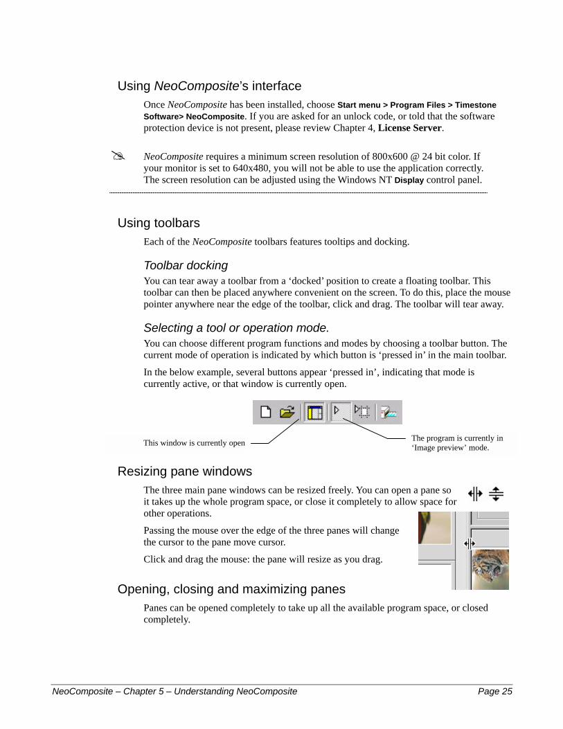
Selecting a tool or operation mode. You can choose different program functions and modes by choosing a toolbar button. The current mode of operation is indicated by which button is ‘pressed in’ in the main toolbar.
In the below example, several buttons appear ‘pressed in’, indicating that mode is currently active, or that window is currently open.
The program is currently in ‘Image preview’ mode.
This window is currently open
Resizing pane windows The three main pane windows can be resized freely. You can open a pane so it takes up the whole program space, or close it completely to allow space for other operations.
Passing the mouse over the edge of the three panes will change the cursor to the pane move cursor.
Click and drag the mouse: the pane will resize as you drag.
Opening, closing and maximizing panes Panes can be opened completely to take up all the available program space, or closed completely.
NeoComposite – Chapter 5 – Understanding NeoComposite Page 25

Opening or closing panes Panes can be opened or closed by choosing the pane name from the View menu. If the chosen pane is currently visible, choosing it from the View menu will close it and vice versa. If a pane is currently visible, there will be a checkmark next to its name in the View menu.
Resizing a pane using the mouse can also open or close a pane. Each pane has a minimum size – if you use the mouse to resize a pane past its minimum size, it will close. It is possible to open a closed pane by grabbing the closed pane edge, and dragging to open it.
Shortcut keys There are many shortcut keys that allow quick selection of program options. These shortcuts are either indicated within a menu selection, or within the palette being used.
For example, if you wish to adjust the image contrast, press and hold the Control key, then the C key. The value in the Contrast adjustment is highlighted ready for use.
Palette shortcut indicated within the palette
Menu shortcut indicated within the menu selection
NeoComposite – Chapter 5 – Understanding NeoComposite Page 26
6 – Co
NeoCompos
6
nfiguring NeoCompositeSetting the Program defaults There are a number of program defaults that need to be set to ensure NeoComposite is most useful to you. Things such as the location of various files, default fields need to be set for your lab.
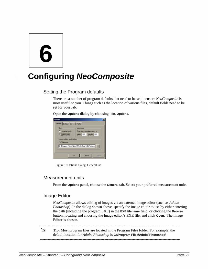
Open the Options dialog by choosing File, Options.
Figure 1: Options dialog, General tab
Measurement units From the Options panel, choose the General tab. Select your preferred measurement units.
Image Editor NeoComposite allows editing of images via an external image editor (such as Adobe Photoshop). In the dialog shown above, specify the image editor to use by either entering the path (including the program EXE) in the EXE filename field, or clicking the Browse button, locating and choosing the Image editor’s EXE file, and click Open. The Image Editor is chosen.
! Tip: Most program files are located in the Program Files folder. For example, the default location for Adobe Photoshop is C:\Program Files\Adobe\Photoshop\
ite – Chapter 6 – Configuring NeoComposite Page 27
Aspect ratios The aspect ratio of the image determines how tall and wide a portrait will be. There are several common aspect ratios used in the photographic world, but you may like to define some that are specific to your needs. The aspect ratio here should match those you design for your Subject blocks. For example, if you design your portrait blocks to have a 4:5 aspect, define this aspect here.
The cropping set here also follows through to other Neo applications. For ease of production, you should use a similar aspect ratio as your other Neo production such as the package prints etc.
Default Aspect Ratios Aspect ratios can be stored as a program default, or added to an image collection. New files will automatically contain the default aspect ratios which can then be added to. Any aspect ratios that you add to an individual file (via Edit, Aspect ratios…) are available only to that file.
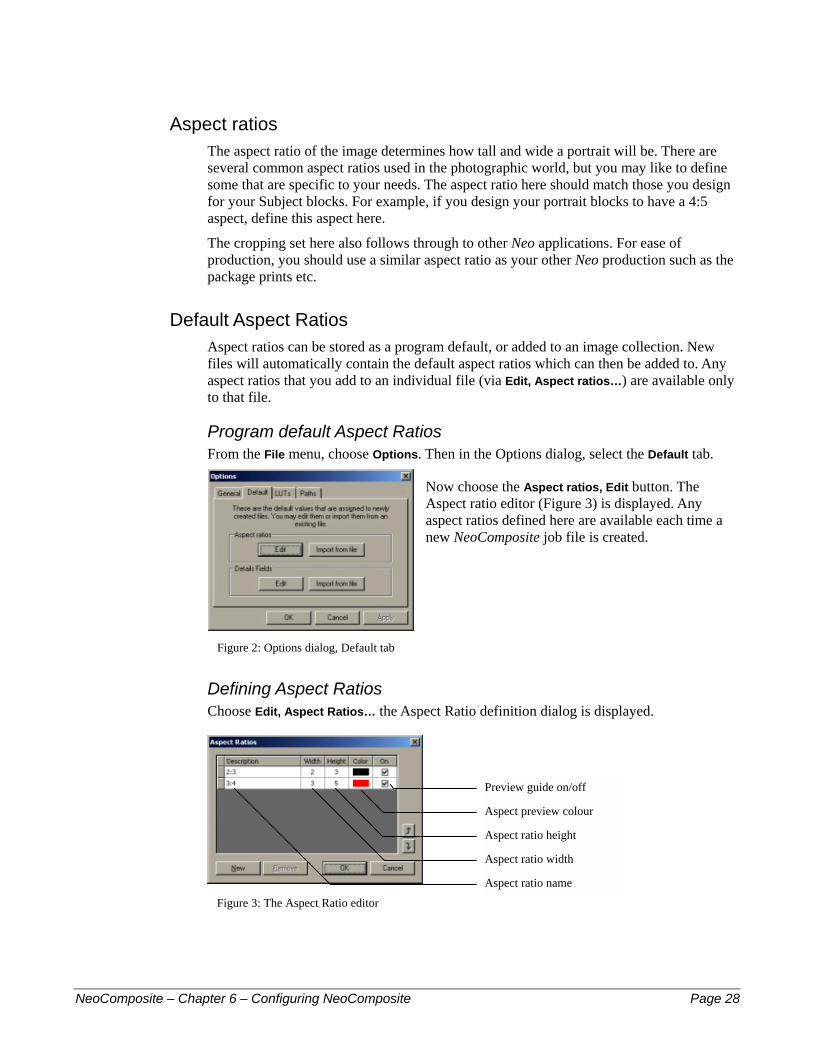
Program default Aspect Ratios From the File menu, choose Options. Then in the Options dialog, select the Default tab.
Now choose the Aspect ratios, Edit button. The Aspect ratio editor (Figure 3) is displayed. Any aspect ratios defined here are available each time a new NeoComposite job file is created.
Figure 2: Options dialog, Default tab
Defining Aspect Ratios Choose Edit, Aspect Ratios… the Aspect Ratio definition dialog is displayed.
Aspect ratio height
Preview guide on/off
Aspect preview colour
Aspect ratio width
Aspect ratio name
Figure 3: The Aspect Ratio editor
NeoComposite – Chapter 6 – Configuring NeoComposite Page 28
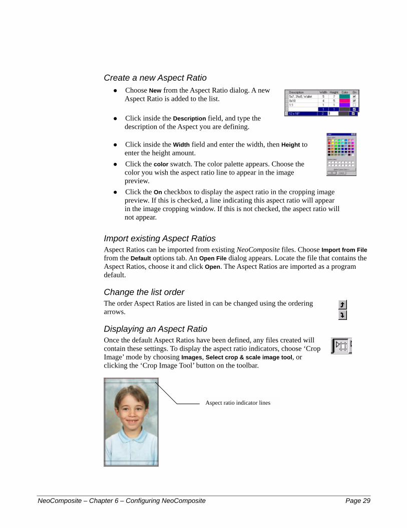
Create a new Aspect Ratio Choose New from the Aspect Ratio dialog. A new Aspect Ratio is added to the list.
#
#
#
#
#
Click inside the Description field, and type the description of the Aspect you are defining.
Click inside the Width field and enter the width, then Height to enter the height amount. Click the color swatch. The color palette appears. Choose the color you wish the aspect ratio line to appear in the image preview. Click the On checkbox to display the aspect ratio in the cropping image preview. If this is checked, a line indicating this aspect ratio will appear in the image cropping window. If this is not checked, the aspect ratio will not appear.
Import existing Aspect Ratios Aspect Ratios can be imported from existing NeoComposite files. Choose Import from File from the Default options tab. An Open File dialog appears. Locate the file that contains the Aspect Ratios, choose it and click Open. The Aspect Ratios are imported as a program default.
Change the list order The order Aspect Ratios are listed in can be changed using the ordering arrows.
Displaying an Aspect Ratio Once the default Aspect Ratios have been defined, any files created will contain these settings. To display the aspect ratio indicators, choose ‘Crop Image’ mode by choosing Images, Select crop & scale image tool, or clicking the ‘Crop Image Tool’ button on the toolbar.
Aspect ratio indicator lines
NeoComposite – Chapter 6 – Configuring NeoComposite Page 29

Default fields Various information fields are used in NeoComposite. Certain of these fields are best set as program defaults, so that when you create a new job file, it will inherit these default values and you won't have to spend time re-configuring NeoComposite to work the way it did with your previous job file.
Once you’re familiar with how these fields are used, you can set the program defaults.
Adding default fields Choose File, Options then choose the Default tab. The Options dialog appears, as shown in Figure 2. Now click the Details Fields, Edit button.
The Data Fields dialog is displayed. Note there are three tabs – Subject fields, Folder fields and File fields.
Figure 4: The Data Fields editor
Field type Purpose…
Subject fields …contain information about each subject appearing as a name in the shoot list or data to be imported to match against images
Folder fields are objects that are allocated to a particular folder, or a parent folder of a sub folder. Useful fields include the campus name for a school campus, or a year’s mascot.
File fields …are objects that are common to all the groups involved in the current job. Things like the school name, school logo and the like are good examples of File fields.
The Subject Fields tab The Subjects Field tab contains fields that pertain to each subject appearing as a name in a row list. Please see Chapter 8, Details Mode for more information.
Adding a new field Click Add. A new line appears. Click the cursor in the Name entry area, and type the field name.
! Fields are case sensitive. If you define a field ‘Name’, but place and @ code ‘@name’ in a template, the text will not be correctly substituted.
Assigning special attributes A field can be assigned a special attribute that identifies it for special use within the program. Attributes such as first, last or whole name identify a particular field. To assign a field attribute, choose the field, then click the Special drop-down list for that field. A list of available attributes is displayed.
NeoComposite – Chapter 6 – Configuring NeoComposite Page 30

Figure 5: Assigning a Field Attribute
There are several special fields that are built-in to NeoComposite that are always identified as a special field. For the Subject Fields, these special fields are:
Field Name Identified as…
FirstName Identified as a subject’s first name
LastName Identified as a subject’s last name
WholeName Identified as the subject’s whole name
The Folder Fields tab You can define default folder fields in this tab.
The File Fields tab You can define default folder fields in this tab.
Once you have set the desired fields, choose OK.
NeoComposite – Chapter 6 – Configuring NeoComposite Page 31

Defining the Image file location NeoComposite imports the images used for your production in two different ways. The original high-res image file can be imported to the job file, meaning that the external files are no longer required by NeoComposite. Alternately, images can be imported with a reference to the high resolution image. When importing images this way, a smaller screen resolution version of the image is created for use on-screen, and all corrections are saved as instructions to be applied to the original hi-res images when the jobs are printed.
If you accept the default import setting and reference the hi-res originals rather than fully importing them, NeoComposite can record the exact location of the files when they are imported, or you can direct it to look for the files in specific locations on your hard disk, or over the network.
Record the original import location If you import images using the Remember the actual path option, there is no need to define any default paths. See Chapter 6, Configuring NeoComposite for details.
Creating an Image directory In larger labs, it is useful to set up a base image directory to store the image files. There are several ways NeoComposite can locate the required image files -
Image Root directory #
#
#
Same directory as job file Sub-directory from job file
Image Root directory Using an image root directory allows all images belonging to a job be stored under a single directory in its own folder. For example, you might set up a single image server named ImageServer. This server has a drive shared as Data, and all images are stored in folders under the \Images folder.
UNC naming allows this exact directory be specified from any workstation within the network, without using drive letters. This avoids configuration errors. The UNC name for a shared directory is \\Server\Share\Path.
You may set your images up on this server as follows: \Images\Job1 \Images\Job2 \Images\Job3
Only the root folder is required. In this case, The root folder is \Images. So, the UNC name for the path would be: \\ImageServer\Data\Images\
Finally, we need to specify the final search directory to find the source images. Using the @+ code, NeoComposite adds the name of the .TNJ file to the search path as the final part of the path statement. In the above case, each of the .TNJ files would be named Job1, Job2 and Job3.
NeoComposite – Chapter 6 – Configuring NeoComposite Page 32
So, if the path is entered as: \\ImageServer\Data\Images\@+
and the file currently open is called Job2, NeoComposite will search for the original source images in:
\\ImageServer\Data\Images\Job2\
Same directory as job file If the path statement is entered as:
.\
NeoComposite will search for the source images in the same directory as the .TNJ file.
Sub-directory from job file Images can be stored in a sub-directory of the folder that contains the job file. For example, if the job file is stored in a folder \Images\Job1, and the images belonging to that job in \Images\Job1\Source. If the path statement is entered as:
\Source
NeoComposite will search for the source images in the \Source subdirectory.
Defining the Design File location Templates can be stored in various places within your local area. The location of the templates must be defined before NeoComposite will ‘see’ them, ready for you to use.
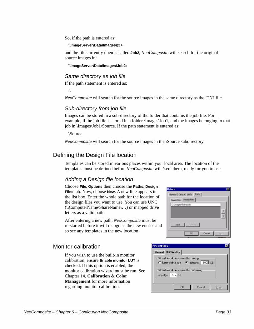
Adding a Design file location Choose File, Options then choose the Paths, Design Files tab. Now, choose New. A new line appears in the list box. Enter the whole path for the location of the design files you want to use. You can use UNC (\\ComputerName\ShareName\…) or mapped drive letters as a valid path.
After entering a new path, NeoComposite must be re-started before it will recognise the new entries and so see any templates in the new location.
Monitor calibration If you wish to use the built-in monitor calibration, ensure Enable monitor LUT is checked. If this option is enabled, the monitor calibration wizard must be run. See Chapter 14, Calibration & Color Management for more information regarding monitor calibration.
NeoComposite – Chapter 6 – Configuring NeoComposite Page 33
7 – Jo
NeoCompos
7
b filesJob files are self-contained files that contain the various bits of information used to create all the pages for a job. When a file is created by choosing File > New, it inherits default settings made in the Options panel (see a previous chapter). You can add or modify these settings once the file has been created. There are several settings that can be made specific to the job file.
Image import options NeoComposite needs to import the images you wish to use to a job file. The import process creates the small on-screen preview that is used when you are preforming all tasks within NeoComposite. The preview image is stored using JPEG compression in the job file.
Creating a new NeoComposite file Start the NeoComposite application, then choose File > New, or click the New Document button in the toolbar. The New File dialog is displayed. Choose the desired location, give the file a name and choose Save. The file is saved, and an empty job file is displayed.
Specify the preview image size The size of the preview image can be changed from the Options menu. The default size of 512k is usually sufficient for most operations, but you might like to increase the size to improve the appearance of the preview. The larger the image preview, the larger the job file. It is also possible that the program may slow if the preview image is set too high. The preview size must be set for each file you create, before images have been imported.
To change the preview size, choose File > Properties. The File Properties dialog is displayed. Choose the Bitmap sizes tab, and make the desired setting in the Stored size of bitmap used for previewing.
ite – Chapter 7 – Job files Page 34
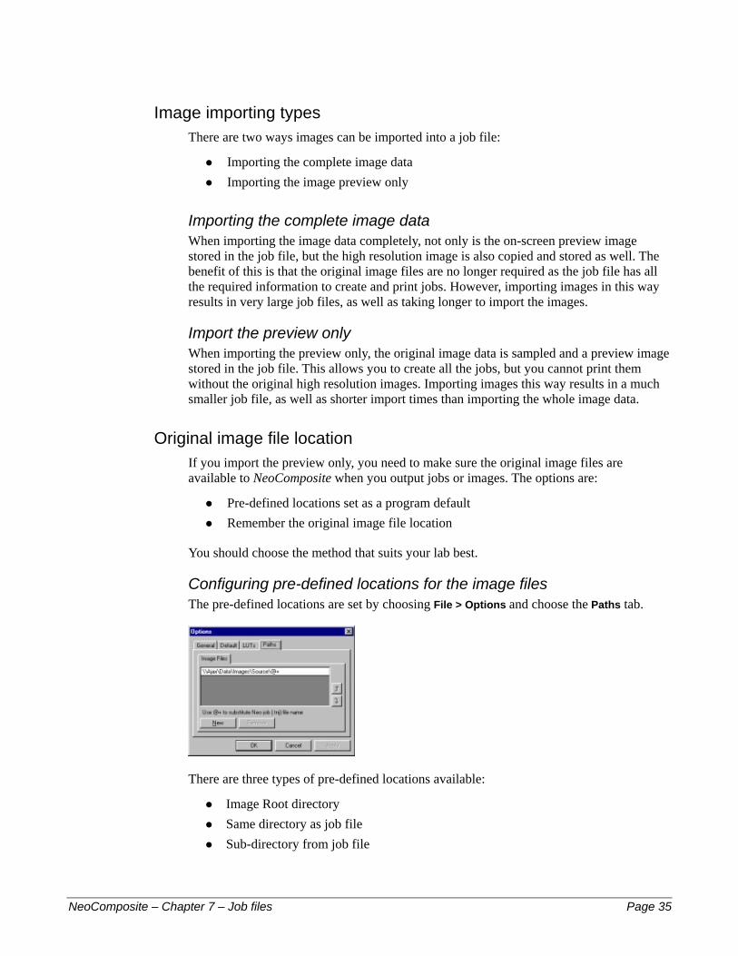
Image importing types There are two ways images can be imported into a job file:
Importing the complete image data #
#
#
#
Importing the image preview only
Importing the complete image data When importing the image data completely, not only is the on-screen preview image stored in the job file, but the high resolution image is also copied and stored as well. The benefit of this is that the original image files are no longer required as the job file has all the required information to create and print jobs. However, importing images in this way results in very large job files, as well as taking longer to import the images.
Import the preview only When importing the preview only, the original image data is sampled and a preview image stored in the job file. This allows you to create all the jobs, but you cannot print them without the original high resolution images. Importing images this way results in a much smaller job file, as well as shorter import times than importing the whole image data.
Original image file location If you import the preview only, you need to make sure the original image files are available to NeoComposite when you output jobs or images. The options are:
Pre-defined locations set as a program default Remember the original image file location
You should choose the method that suits your lab best.
Configuring pre-defined locations for the image files The pre-defined locations are set by choosing File > Options and choose the Paths tab.
There are three types of pre-defined locations available:
Image Root directory #
#
#
Same directory as job file Sub-directory from job file
NeoComposite – Chapter 7 – Job files Page 35
Image Root directory Using an image root directory allows all images belonging to a job be stored under a single directory in its own folder. For example, you might set up a single image server named ImageServer. This server has a drive shared as Data, and all images are stored in folders under the \Images folder.
UNC naming allows this exact directory be specified from any workstation within the network, without using drive letters. This avoids configuration errors. The UNC name for a shared directory is \\Server\Share\Path.
You may set your images up on this server as follows: \Images\Job1 \Images\Job2 \Images\Job3
Only the root folder is required. In this case, The root folder is \Images. So, the UNC name for the path would be: \\ImageServer\Data\Images\
Finally, we need to specify the final search directory to find the source images. Using the @+ code, NeoComposite adds the name of the .TNJ file to the search path as the final part of the path statement. In the above case, each of the .TNJ files would be named Job1, Job2 and Job3.
So, if the path is entered as: \\ImageServer\Data\Images\@+
and the file currently open is called Job2, NeoComposite will search for the original source images in:
\\ImageServer\Data\Images\Job2\
Same directory as job file If the path statement is entered as:
.\
NeoComposite will search for the source images in the same directory as the .TNJ file.
Sub-directory from job file Images can be stored in a sub-directory of the folder that contains the job file. For example, the job file is stored in a folder \Images\Job1, and the images belonging to that job in \Images\Job1\Source. If the path statement is entered as:
\Source
NeoComposite will search for the source images in the \Source subdirectory.
Missing image files If the original image files are not available when printing or exporting the images, an error is shown.
NeoComposite – Chapter 7 – Job files Page 36

Either fix the problem and choose Retry to retry the job, or Abort to abort the current operation.
Image numbering – indexed or sequential Many labs using large numbers of images have various systems of tracking the images. This can mean that the image files that are imported can have a unique and important name or number embedded in their filename. These uniquely named files are called indexed images. Images that don’t contain such special images are imported in a sequential order.
Sequential images When importing sequential images, it is only important to retain the same image order as was on the original film. In this case, the image files should be named in shoot order (i.e. 0001 – 9999). When NeoComposite imports them, the order is retained.
Indexed images Many labs use cameras or film editors that can allocate unique numbers to a particular negative or image. This number can then be used to record various data within other management systems in the lab. For example, the Lucht ‘Shooter File’ records pack order, color corrections and other essential information that is used to create the required prints.
When importing images to NeoComposite that have come from such a system, it is possible to retain the essential index number and so create the packs in the same manner as would be normal in this workflow.
Sequential vs. Indexed images The following screen shots show an indexed and sequentially numbered file. Note the difference in image numbers.
Figure 6: An indexed image set
Figure 7: A sequentially numbered image set
NeoComposite – Chapter 7 – Job files Page 37
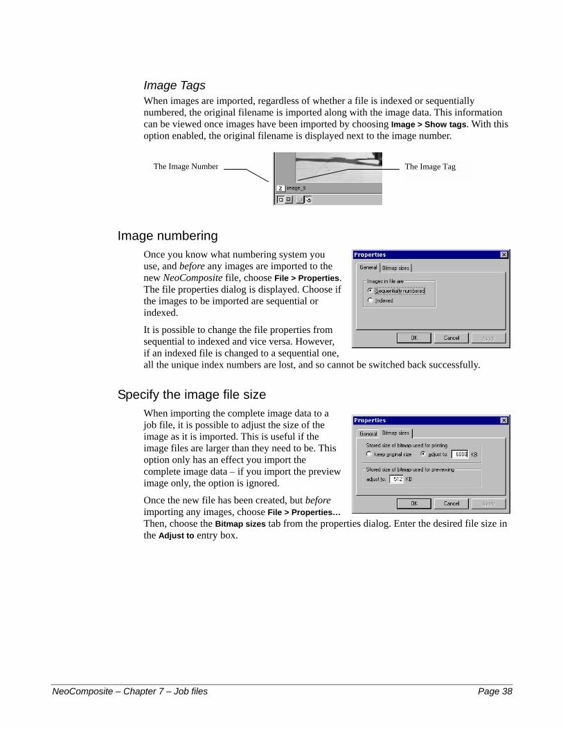
Image Tags When images are imported, regardless of whether a file is indexed or sequentially numbered, the original filename is imported along with the image data. This information can be viewed once images have been imported by choosing Image > Show tags. With this option enabled, the original filename is displayed next to the image number.
The Image Number The Image Tag
Image numbering Once you know what numbering system you use, and before any images are imported to the new NeoComposite file, choose File > Properties. The file properties dialog is displayed. Choose if the images to be imported are sequential or indexed.
It is possible to change the file properties from sequential to indexed and vice versa. However, if an indexed file is changed to a sequential one, all the unique index numbers are lost, and so cannot be switched back successfully.
Specify the image file size When importing the complete image data to a job file, it is possible to adjust the size of the image as it is imported. This is useful if the image files are larger than they need to be. This option only has an effect you import the complete image data – if you import the preview image only, the option is ignored.
Once the new file has been created, but before importing any images, choose File > Properties… Then, choose the Bitmap sizes tab from the properties dialog. Enter the desired file size in the Adjust to entry box.
NeoComposite – Chapter 7 – Job files Page 38
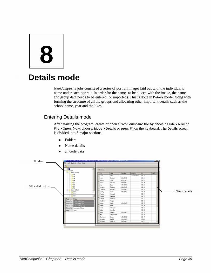
8 – De
Fo
Allocat
NeoCompos
8
tails modeNeoComposite jobs consist of a series of portrait images laid out with the individual’s name under each portrait. In order for the names to be placed with the image, the name and group data needs to be entered (or imported). This is done in Details mode, along with forming the structure of all the groups and allocating other important details such as the school name, year and the likes.
Entering Details mode After starting the program, create or open a NeoComposite file by choosing File > New or File > Open. Now, choose, Mode > Details or press F4 on the keyboard. The Details screen is divided into 3 major sections:
Folders #
#
#
Name details @ code data
lders
ed fieldsName details
ite – Chapter 8 – Details mode Page 39
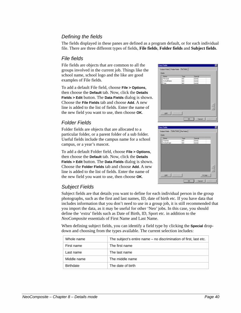
Defining the fields The fields displayed in these panes are defined as a program default, or for each individual file. There are three different types of fields, File fields, Folder fields and Subject fields.
File fields File fields are objects that are common to all the groups involved in the current job. Things like the school name, school logo and the like are good examples of File fields.
To add a default File field, choose File > Options, then choose the Default tab. Now, click the Details Fields > Edit button. The Data Fields dialog is shown. Choose the File Fields tab and choose Add. A new line is added to the list of fields. Enter the name of the new field you want to use, then choose OK.
Folder Fields Folder fields are objects that are allocated to a particular folder, or a parent folder of a sub folder. Useful fields include the campus name for a school campus, or a year’s mascot.
To add a default Folder field, choose File > Options, then choose the Default tab. Now, click the Details Fields > Edit button. The Data Fields dialog is shown. Choose the Folder Fields tab and choose Add. A new line is added to the list of fields. Enter the name of the new field you want to use, then choose OK.
Subject Fields Subject fields are that details you want to define for each individual person in the group photographs, such as the first and last names, ID, date of birth etc. If you have data that includes information that you don’t need to use in a group job, it is still recommended that you import the data, as it may be useful for other ‘Neo’ jobs. In this case, you should define the ‘extra’ fields such as Date of Birth, ID, Sport etc. in addition to the NeoComposite essentials of First Name and Last Name.
When defining subject fields, you can identify a field type by clicking the Special drop-down and choosing from the types available. The current selection includes:
Whole name The subject’s entire name – no discrimination of first, last etc.
First name The first name
Last name The last name
Middle name The middle name
Birthdate The date of birth
NeoComposite – Chapter 8 – Details mode Page 40
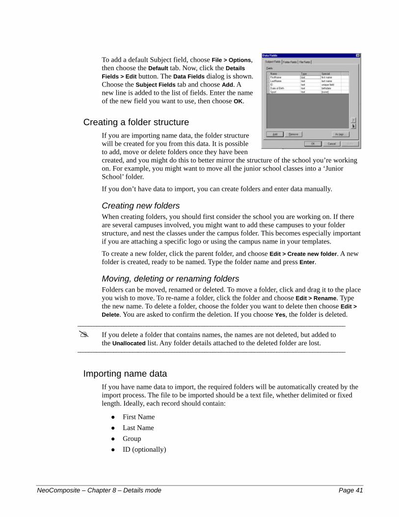
To add a default Subject field, choose File > Options, then choose the Default tab. Now, click the Details Fields > Edit button. The Data Fields dialog is shown. Choose the Subject Fields tab and choose Add. A new line is added to the list of fields. Enter the name of the new field you want to use, then choose OK.
Creating a folder structure If you are importing name data, the folder structure will be created for you from this data. It is possible to add, move or delete folders once they have been created, and you might do this to better mirror the structure of the school you’re working on. For example, you might want to move all the junior school classes into a ‘Junior School’ folder.
If you don’t have data to import, you can create folders and enter data manually.
Creating new folders When creating folders, you should first consider the school you are working on. If there are several campuses involved, you might want to add these campuses to your folder structure, and nest the classes under the campus folder. This becomes especially important if you are attaching a specific logo or using the campus name in your templates.
To create a new folder, click the parent folder, and choose Edit > Create new folder. A new folder is created, ready to be named. Type the folder name and press Enter.
Moving, deleting or renaming folders Folders can be moved, renamed or deleted. To move a folder, click and drag it to the place you wish to move. To re-name a folder, click the folder and choose Edit > Rename. Type the new name. To delete a folder, choose the folder you want to delete then choose Edit > Delete. You are asked to confirm the deletion. If you choose Yes, the folder is deleted.
! If you delete a folder that contains names, the names are not deleted, but added to the Unallocated list. Any folder details attached to the deleted folder are lost.
Importing name data If you have name data to import, the required folders will be automatically created by the import process. The file to be imported should be a text file, whether delimited or fixed length. Ideally, each record should contain:
First Name #
#
#
#
Last Name Group ID (optionally)
NeoComposite – Chapter 8 – Details mode Page 41
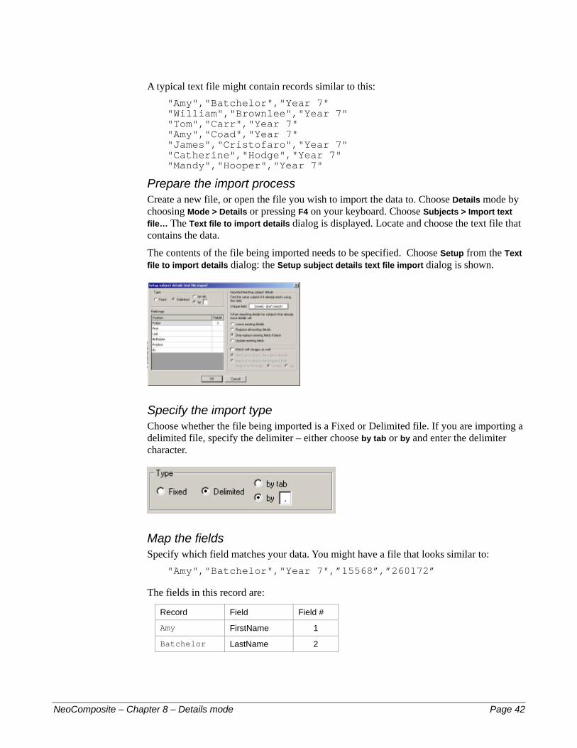
A typical text file might contain records similar to this: "Amy","Batchelor","Year 7" "William","Brownlee","Year 7" "Tom","Carr","Year 7" "Amy","Coad","Year 7" "James","Cristofaro","Year 7" "Catherine","Hodge","Year 7" "Mandy","Hooper","Year 7"
Prepare the import process Create a new file, or open the file you wish to import the data to. Choose Details mode by choosing Mode > Details or pressing F4 on your keyboard. Choose Subjects > Import text file… The Text file to import details dialog is displayed. Locate and choose the text file that contains the data.
The contents of the file being imported needs to be specified. Choose Setup from the Text file to import details dialog: the Setup subject details text file import dialog is shown.
Specify the import type Choose whether the file being imported is a Fixed or Delimited file. If you are importing a delimited file, specify the delimiter – either choose by tab or by and enter the delimiter character.
Map the fields Specify which field matches your data. You might have a file that looks similar to:
"Amy","Batchelor","Year 7",”15568”,”260172”
The fields in this record are:
Record Field Field #
Amy FirstName 1
Batchelor LastName 2
NeoComposite – Chapter 8 – Details mode Page 42
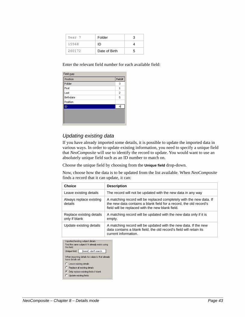
Year 7 Folder 3
15568 ID 4
260172 Date of Birth 5
Enter the relevant field number for each available field:
Updating existing data If you have already imported some details, it is possible to update the imported data in various ways. In order to update existing information, you need to specify a unique field that NeoComposite will use to identify the record to update. You would want to use an absolutely unique field such as an ID number to match on.
Choose the unique field by choosing from the Unique field drop-down.
Now, choose how the data is to be updated from the list available. When NeoComposite finds a record that it can update, it can:
Choice Description
Leave existing details The record will not be updated with the new data in any way
Always replace existing details
A matching record will be replaced completely with the new data. If the new data contains a blank field for a record, the old record’s field will be replaced with the new blank field.
Replace existing details only if blank
A matching record will be updated with the new data only if it is empty.
Update existing details A matching record will be updated with the new data. If the new data contains a blank field, the old record’s field will retain its current information.
NeoComposite – Chapter 8 – Details mode Page 43

Import the name data Once you are happy with the settings, choose OK to dismiss the Setup subject details text file import dialog. Now, confirm the text file has been selected and choose Open. The data is imported.
Importing Shoot List data If you have the name data in shoot order, you can import the names and match them to images at import time. The data you are importing must contain additionally:
A unique ID number for each individual #
#
#
Either – the image number each record matches Or – each record is in the correct shoot order
As it is possible for a single individual to appear several times in a shoot order file, you must have the unique ID number to identify individuals. You will not be able to import the data successfully without this unique field.
Inspecting the data to import The data you have to import might look similar to:
"Amy","Batchelor","Year 7",”00125”,”0012258.jpg” "Amy","Batchelor","Year 7",”00125”,”0012259.jpg” "Amy","Batchelor","Year 7",”00125”,”0012260.jpg” "William","Brownlee","Year 7"",”00127”,”0012261.jpg” "Tom","Carr","Year 7",”00131”,”0012262.jpg” "Amy","Coad","Year 7",”00142”,”0012263.jpg” "Amy","Coad","Year 7",”00142”,”0012264.jpg” "Amy","Coad","Year 7",”00142”,”0012265.jpg” "James","Cristofaro","Year 7",”00194”,”0012266.jpg” "Catherine","Hodge","Year 7",”00167”,”0012267.jpg” "Mandy","Hooper","Year 7",”00111”,”0012268.jpg”
In this example, the fields are set out as:
First, Last, Group, Unique ID, Image Number
You will notice that Amy, Batchelor and Amy Coad both appear 3 times in the text file, indicating that they were photographed 3 times.
In this case, the unique identifier is the ‘ID’ field # 4. By specifying this field, NeoComposite will import the multiple entries and place them only once into the Details. Without this identifier, names that appear multiple times in the imported file would appear incorrectly multiple times in the group details.
By specifying a unique field, NeoComposite can identify which names entries are for the same individual.
Specify the unique field In the Setup dialog, locate the Imported/existing subject details panel. This panel controls how data will be imported or merged.
NeoComposite – Chapter 8 – Details mode Page 44

Unique field Specify which (if any ) of the fields is unique from those available in the drop-down. This will vary according to the fields available in the file.
Matching the images If the data file being imported contains a match link, you can match the names to images when importing the images. You need to identify certain matching parameters for the match to occur correctly. To enable matching on import, check Match with images as well and make the relevant settings.
Set the match parameters If the names in the text file being imported are listed in shoot order, choose Match according to the order in the file. When this option is enabled, a 1 to 1 relationship is assumed to exist between the images and names in the list.
If each record contains an ID and image number, choose Match according to the (image-id) field. There are 2 options – image-id is the image:
Number – when images are imported they are allocated an image number. This number is either a sequential or indexed number. Choose this option if the images are numbered in this fashion.
#
# Tag – each image imported has an image tag – the original file name. If the match is linked to the original file name, use this tag.
Importing the details Once all the settings have been made, choose OK to dismiss the dialog. Choose the file to import in the Text file to import details dialog, then choose Open. The details are imported.
Checking the match The procedure of matching images to names is covered in a further chapter. After the names have been imported and matched as well, you can view the raw match by choosing Mode > Match. If you have not yet imported images, you will see a display that indicates
NeoComposite – Chapter 8 – Details mode Page 45
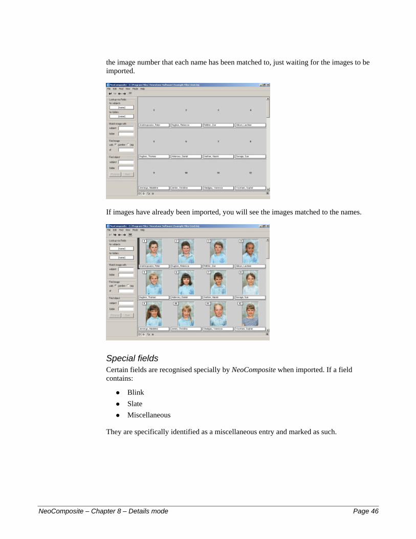
the image number that each name has been matched to, just waiting for the images to be imported.
If images have already been imported, you will see the images matched to the names.
Special fields Certain fields are recognised specially by NeoComposite when imported. If a field contains:
Blink #
#
#
Slate Miscellaneous
They are specifically identified as a miscellaneous entry and marked as such.
NeoComposite – Chapter 8 – Details mode Page 46
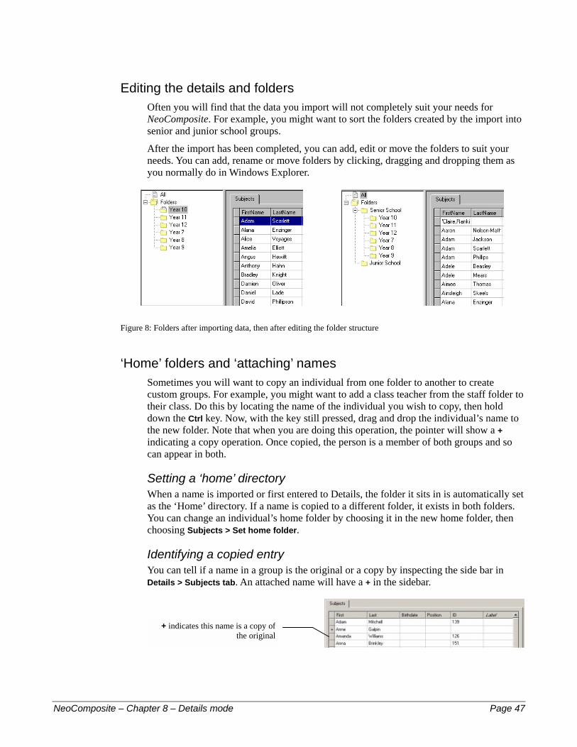
Editing the details and folders Often you will find that the data you import will not completely suit your needs for NeoComposite. For example, you might want to sort the folders created by the import into senior and junior school groups.
After the import has been completed, you can add, edit or move the folders to suit your needs. You can add, rename or move folders by clicking, dragging and dropping them as you normally do in Windows Explorer.
Figure 8: Folders after importing data, then after editing the folder structure
‘Home’ folders and ‘attaching’ names Sometimes you will want to copy an individual from one folder to another to create custom groups. For example, you might want to add a class teacher from the staff folder to their class. Do this by locating the name of the individual you wish to copy, then hold down the Ctrl key. Now, with the key still pressed, drag and drop the individual’s name to the new folder. Note that when you are doing this operation, the pointer will show a + indicating a copy operation. Once copied, the person is a member of both groups and so can appear in both.
Setting a ‘home’ directory When a name is imported or first entered to Details, the folder it sits in is automatically set as the ‘Home’ directory. If a name is copied to a different folder, it exists in both folders. You can change an individual’s home folder by choosing it in the new home folder, then choosing Subjects > Set home folder.
Identifying a copied entry You can tell if a name in a group is the original or a copy by inspecting the side bar in Details > Subjects tab. An attached name will have a + in the sidebar.
+ indicates this name is a copy ofthe original
NeoComposite – Chapter 8 – Details mode Page 47
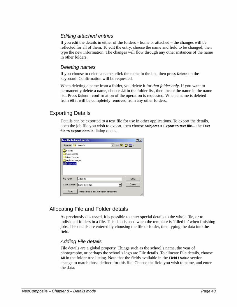
Editing attached entries If you edit the details in either of the folders – home or attached – the changes will be reflected for all of them. To edit the entry, choose the name and field to be changed, then type the new information. The changes will flow through any other instances of the name in other folders.
Deleting names If you choose to delete a name, click the name in the list, then press Delete on the keyboard. Confirmation will be requested.
When deleting a name from a folder, you delete it for that folder only. If you want to permanently delete a name, choose All in the folder list, then locate the name in the name list. Press Delete - confirmation of the operation is requested. When a name is deleted from All it will be completely removed from any other folders.
Exporting Details Details can be exported to a text file for use in other applications. To export the details, open the job file you wish to export, then choose Subjects > Export to text file… the Text file to export details dialog opens.
Allocating File and Folder details As previously discussed, it is possible to enter special details to the whole file, or to individual folders in a file. This data is used when the template is ‘filled in’ when finishing jobs. The details are entered by choosing the file or folder, then typing the data into the field.
Adding File details File details are a global property. Things such as the school’s name, the year of photography, or perhaps the school’s logo are File details. To allocate File details, choose All in the folder tree listing. Note that the fields available in the Field / Value section change to match those defined for this file. Choose the field you wish to name, and enter the data.
NeoComposite – Chapter 8 – Details mode Page 48

Adding Folder details Folder details can apply at several levels. For example, you might have a folder ‘Senior School’ that contains all the senior groups. You might want to use ‘Senior School’ as a part of the final group image (the board might read ‘Provident High School – Senior School – Year 10A’). Rather than create a template that contains ‘Senior School’ written as plain text, you can include a special code that instructs NeoComposite to look for the text it should insert. So, your template could be used for the Junior School, as well as the Senior School without changing it.
NeoComposite uses a ‘searching’ mechanism that allows you to specify information that belongs to a number of groups, as well as information for an individual group. In the below example, Year 10A is a member of the Year 10 folder, which is a member of the Senior School folder. Clicking on the ‘Senior School’ folder reveals that the field ‘SchoolType’ is available. In the case of the ‘Senior School’ folder, click in ‘SchoolType’ and enter the name that will appear in the template. When the job is run, NeoComposite will place ‘Senior School’ into the template for all the Senior School groups.
To enter the information, click the folder, and then the Value for the field you need. Type the data.
Multi-line Value entries Field values can contain a carriage return, allowing a single value to be spread over several lines. This is done by entering a special code in the Value field.
To enter a carriage return, type the first line, then either:
Press <Control> <Enter> #
# Press the Numeric Keypad <Enter> key
The ¶ symbol is placed into the text.
NeoComposite – Chapter 8 – Details mode Page 49

Inserted Carriage return
Labels NeoComposite allows individuals in the Details to be labeled with a special attribute. An individual might be the School’s principal, or the School Captain. By labelling them as ‘Principal’ or ‘SchoolCaptain’ (the label name is up to you), you can design a template that uses a reference to ‘@Principal’ or ‘@SchoolCaptain’. When the template is used, the image the labelled person is inserted to the finished page.
A Label reference in a board template
Causes the ‘Principal’ portrait to be placed into the finished page
‘Global’ label Some individuals are common for every group in the school – for example, the School’s Principal.
Labeling an individual In Details mode, locate the individual then type the label in the Label column.
Folder specific labels Some individuals are specific to a folder or group – for example the class teacher. Because there can be many class teachers, you must label them on a ‘per page’ basis. See the later chapter for these details.
Labeled Holders NeoPack/Professional templates can include referenced images that are placed into the final design. These referenced images are created in Design mode for either the entire file, or individual folders. This is especially useful if your template designs include a school
NeoComposite – Chapter 8 – Details mode Page 50
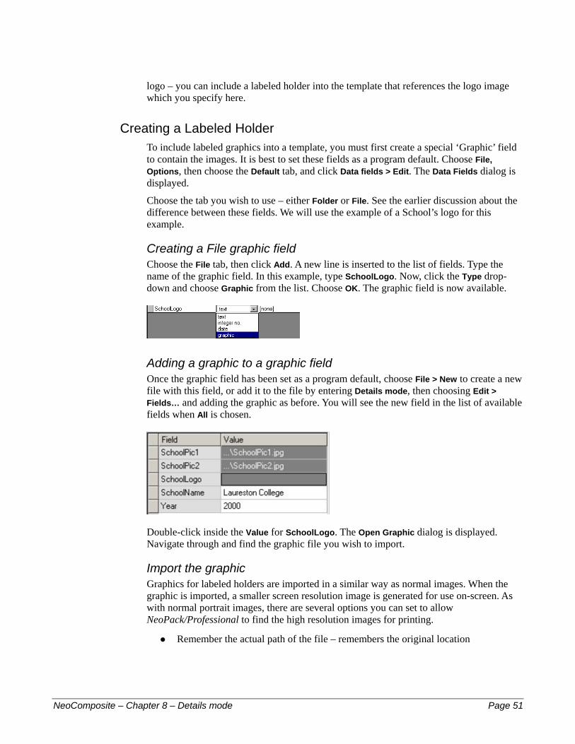
logo – you can include a labeled holder into the template that references the logo image which you specify here.
Creating a Labeled Holder To include labeled graphics into a template, you must first create a special ‘Graphic’ field to contain the images. It is best to set these fields as a program default. Choose File, Options, then choose the Default tab, and click Data fields > Edit. The Data Fields dialog is displayed.
Choose the tab you wish to use – either Folder or File. See the earlier discussion about the difference between these fields. We will use the example of a School’s logo for this example.
Creating a File graphic field Choose the File tab, then click Add. A new line is inserted to the list of fields. Type the name of the graphic field. In this example, type SchoolLogo. Now, click the Type drop-down and choose Graphic from the list. Choose OK. The graphic field is now available.
Adding a graphic to a graphic field Once the graphic field has been set as a program default, choose File > New to create a new file with this field, or add it to the file by entering Details mode, then choosing Edit > Fields… and adding the graphic as before. You will see the new field in the list of available fields when All is chosen.
Double-click inside the Value for SchoolLogo. The Open Graphic dialog is displayed. Navigate through and find the graphic file you wish to import.
Import the graphic Graphics for labeled holders are imported in a similar way as normal images. When the graphic is imported, a smaller screen resolution image is generated for use on-screen. As with normal portrait images, there are several options you can set to allow NeoPack/Professional to find the high resolution images for printing.
Remember the actual path of the file – remembers the original location #
NeoComposite – Chapter 8 – Details mode Page 51

Discard the path – use the file searching options discussed in Chapter 9, Images mode.
#
Load the graphic image Choose the import option you wish to use, then choose Select file… A File > Open dialog appears. Choose the image file, the reference options, then Open. The graphic is displayed.
Choosing the transparent area You can specify two types of mask that allow transparent areas in the logo.
Simple transparency mask If the logo has areas you would like to be transparent as a single color, click it in the preview. Note the hashed area indicating transparency. To clear the set transparency, click No mask.
! Make sure you design your logo graphics carefully. Any area that is the same color as you click will appear as transparent in your design. Pay careful attention to the edges of the logo as grey edges around the logo can appear as a light halo in the finished page. Don’t save the logo file in JPEG format, as you might also see a halo due to the image compression. Use a lossless compression method like PNG or similar.
Using a transparency mask More complex 8 bit masks allows more complex effects like soft edged blends etc. To set the 8 bit mask, click Mask file… the Set Mask dialog opens. Choose Load, then find the transparency mask file and click Open. The mask is loaded and displayed. If you need to adjust the orientation of the mask, choose from the rotate or flip options in the Set Mask dialog.
NeoComposite – Chapter 8 – Details mode Page 52
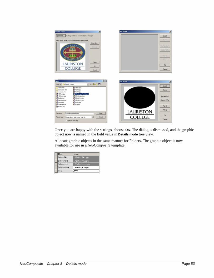
Once you are happy with the settings, choose OK. The dialog is dismissed, and the graphic object now is named in the field value in Details mode tree view.
Allocate graphic objects in the same manner for Folders. The graphic object is now available for use in a NeoComposite template.
NeoComposite – Chapter 8 – Details mode Page 53
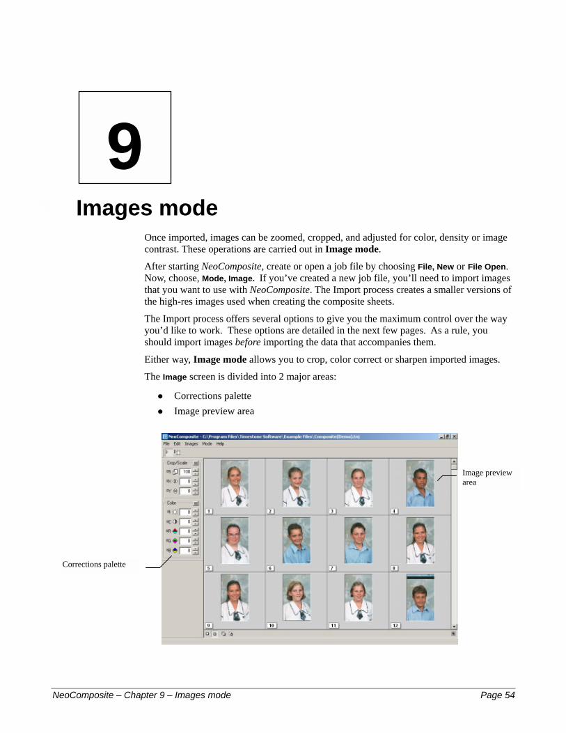
9 – Im
Corrections
NeoCompos
9
ages modeOnce imported, images can be zoomed, cropped, and adjusted for color, density or image contrast. These operations are carried out in Image mode.
After starting NeoComposite, create or open a job file by choosing File, New or File Open. Now, choose, Mode, Image. If you’ve created a new job file, you’ll need to import images that you want to use with NeoComposite. The Import process creates a smaller versions of the high-res images used when creating the composite sheets.
The Import process offers several options to give you the maximum control over the way you’d like to work. These options are detailed in the next few pages. As a rule, you should import images before importing the data that accompanies them.
Either way, Image mode allows you to crop, color correct or sharpen imported images.
The Image screen is divided into 2 major areas:
Corrections palette #
# Image preview area
Image preview area
palette
ite – Chapter 9 – Images mode Page 54
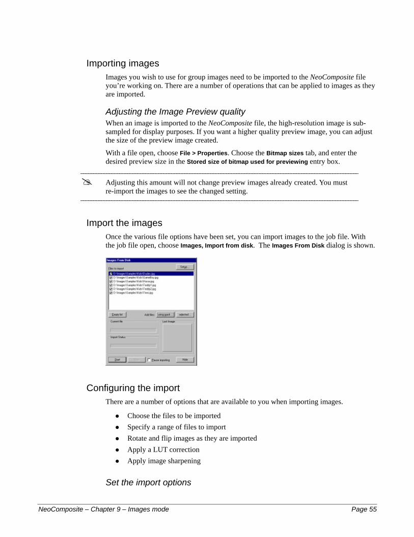
Importing images Images you wish to use for group images need to be imported to the NeoComposite file you’re working on. There are a number of operations that can be applied to images as they are imported.
Adjusting the Image Preview quality When an image is imported to the NeoComposite file, the high-resolution image is sub-sampled for display purposes. If you want a higher quality preview image, you can adjust the size of the preview image created.
With a file open, choose File > Properties. Choose the Bitmap sizes tab, and enter the desired preview size in the Stored size of bitmap used for previewing entry box.
! Adjusting this amount will not change preview images already created. You must re-import the images to see the changed setting.
Import the images Once the various file options have been set, you can import images to the job file. With the job file open, choose Images, Import from disk. The Images From Disk dialog is shown.
Configuring the import There are a number of options that are available to you when importing images.
Choose the files to be imported #
#
#
#
#
Specify a range of files to import Rotate and flip images as they are imported Apply a LUT correction Apply image sharpening
Set the import options
NeoComposite – Chapter 9 – Images mode Page 55
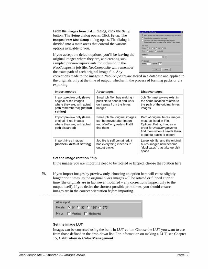
From the Images from disk… dialog, click the Setup button. The Setup dialog opens. Click Setup. The Images From Disk Setup dialog opens. The dialog is divided into 4 main areas that control the various options available to you.
If you accept the default options, you’ll be leaving the original images where they are, and creating sub-sampled preview equivalents for inclusion in the NeoComposite job file. NeoComposite will remember the exact path of each original image file. Any corrections made to the images in NeoComposite are stored in a database and applied to the originals only at the time of output, whether in the process of forming packs or via exporting.
Import method Advantages Disadvantages
Import preview only (leave original hi-res images where they are, with actual path remembered) (default setting)
Small job file, thus making it possible to send it and work on it away from the hi-res images
Job file must always exist in the same location relative to the path of the original hi-res images
Import preview only (leave original hi-res images where they are, with actual path discarded)
Small job file, original images can be moved after import and NeoComposite will still find them
Path of original hi-res images must be listed in File, Options, Paths, Images in order for NeoComposite to find them when it needs them to output packs or export
Import hi-res images (uncheck default setting)
Job file is self contained, it has everything it needs to output packs
Large job file, and the original hi-res images now become "duplicates" that take up disk space
Set the image rotation / flip If the images you are importing need to be rotated or flipped, choose the rotation here.
! If you import images by preview only, choosing an option here will cause slightly longer print times, as the original hi-res images will be rotated or flipped at print time (the originals are in fact never modified – any corrections happen only to the output itself). If you desire the shortest possible print times, you should ensure images are in the correct orientation before importing.
Set the image LUT Images can be corrected using the built-in LUT editor. Choose the LUT you want to use from those defined in the drop-down list. For information on making a LUT, see Chapter 15, Calibration & Color Management.
NeoComposite – Chapter 9 – Images mode Page 56
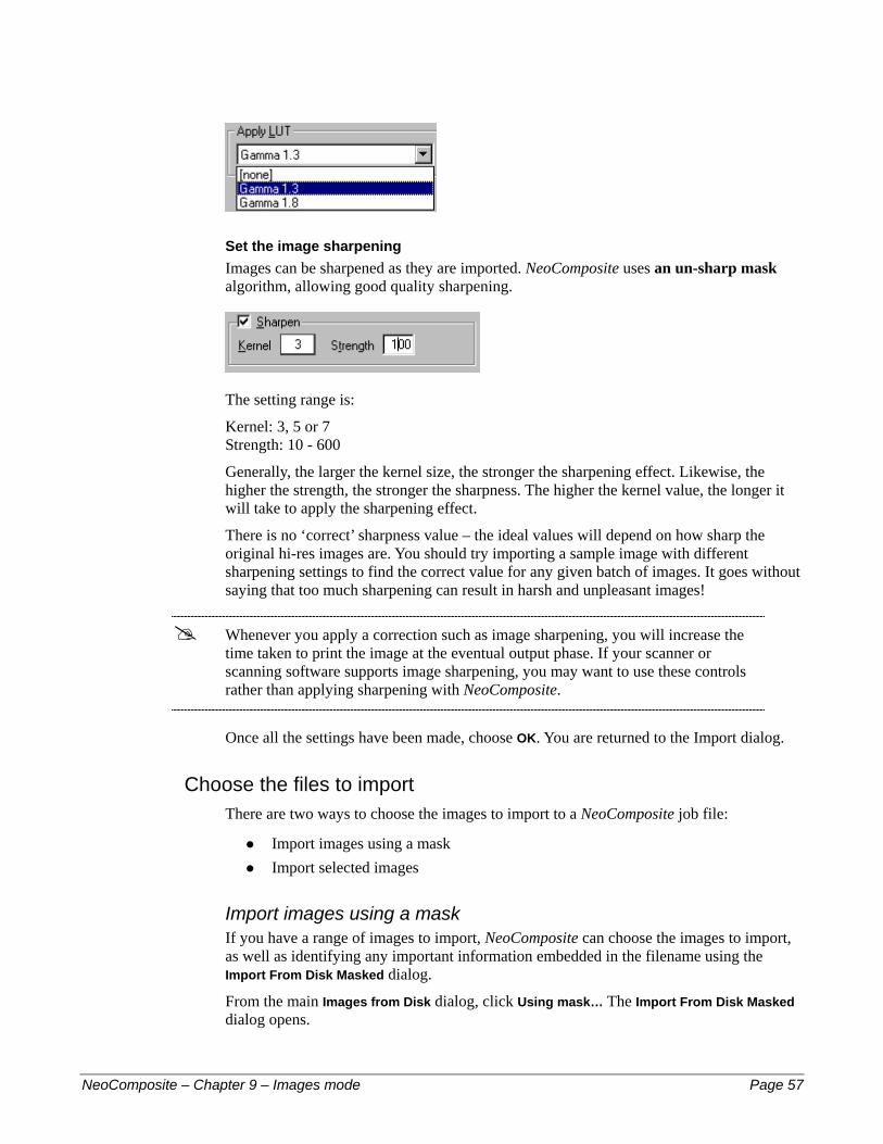
Set the image sharpening Images can be sharpened as they are imported. NeoComposite uses an un-sharp mask algorithm, allowing good quality sharpening.
The setting range is:
Kernel: 3, 5 or 7 Strength: 10 - 600
Generally, the larger the kernel size, the stronger the sharpening effect. Likewise, the higher the strength, the stronger the sharpness. The higher the kernel value, the longer it will take to apply the sharpening effect.
There is no ‘correct’ sharpness value – the ideal values will depend on how sharp the original hi-res images are. You should try importing a sample image with different sharpening settings to find the correct value for any given batch of images. It goes without saying that too much sharpening can result in harsh and unpleasant images!
! Whenever you apply a correction such as image sharpening, you will increase the time taken to print the image at the eventual output phase. If your scanner or scanning software supports image sharpening, you may want to use these controls rather than applying sharpening with NeoComposite.
Once all the settings have been made, choose OK. You are returned to the Import dialog.
Choose the files to import There are two ways to choose the images to import to a NeoComposite job file:
Import images using a mask #
# Import selected images
Import images using a mask If you have a range of images to import, NeoComposite can choose the images to import, as well as identifying any important information embedded in the filename using the Import From Disk Masked dialog.
From the main Images from Disk dialog, click Using mask… The Import From Disk Masked dialog opens.
NeoComposite – Chapter 9 – Images mode Page 57

Choose the image directory Enter the path to the image files you want to import. You can click the Browse button to open a Browse dialog.
Specify the file range to import NeoComposite can use a mask to select the files to import, as well as identify important information embedded in a filename.
For example, a set of files might be named:
Image 1 Image001exp.tif
Image 2 Image002exp.tif
Image 3 Image003exp.tif
… Imagexxxexp.tif
These filenames consist of a prefix, the unique number, then a ‘postfix’:
prefix: img #
#
#
#
#
#
#
#
number: 001 – xxx, 3 digits long postfix: exp extension: tif
The important information can be imported along with the image data by specifying the location of the data within the filename. In this case, you would enter:
‘Image’ as the pre entry 3 as the no-width entry ‘exp’ as the post entry ‘tif’ as the ext entry
With these settings made, any files that don’t conform to this filename mask will be ignored. If the pre, no-width and post fields are left blank, any eligible .tif files found in the specified directory will be imported.
Specify a file range limit You can choose to import a range of images from the valid range. For example, if you want to import image 20 to 40 out of 100 valid image files, you would enter 20 and 40 in the Limit from image no… to image no boxes. Image files 20 through 40 will be imported.
Once you have made all the settings, choose OK. The Images From Disk Masked dialog is dismissed. Note that in the main Images From Disk dialog, you will now see a list of the files that will be imported according to the entries made.
NeoComposite – Chapter 9 – Images mode Page 58

Import selected images If you want to import a number of selected image files, you can choose the files to import using the selected… dialog. Click Selected. The Import From Disk dialog opens. Choose the files you want to import. You can use the standard Windows modifier keys to select the various file ranges. These modifiers are:
<Shift> click first then last file in a range – selects a block of files.
#
# <CTRL> click each file you wish to import – selects the files to import individually
Choose the range of files to and choose OK.
Specify the image import order Open the Import Options panel by choosing Images, Import options panel… Note the status of the Incoming images section of the Import Options. If the file currently open is indexed, the options will be unavailable. If the file currently open is sequential, the options will be available.
Images imported to a sequential file are numbThe images are imported in order according tpanel dialog.
NeoComposite – Chapter 9 – Images mode
Image options available for asequential file
Unavailable Image options for an indexed file
ered internally with a sequential number. o the parameters set in the Import options
Page 59

Once images are imported to a sequential file, they will have numbers allocated from 1 to however many images are in the file (1, 2, 3, 4…)
Various import options are available:
Reverse order: Imports images in reverse numeric order (999 first, to 001)
#
#
#
#
!
To end: Appends all new images to the end of existing images. If Reverse order is selected, images are appended before the first image (if it exists). Insert: Inserts imported files from the currently selected image (only available if images have already been imported). Replace: Imported files overwrite existing images from the one currently selected (only available if images have already been imported).
If Insert is selected as the import option, images are inserted from the point of the image currently selected. If you select a new image during the import, the insertion position is retained. If you want to specify a new insertion point for imported images, pause the import by choosing Pause import, the new insertion point, then click Insert once again in the Import options panel. The new insertion point is set.
Start the import Once all the various settings have been made, choose Start. You’ll be able to see the images as they are imported, while the Import Status section of the Images from Disk dialog will keep you informed of the progress. Choosing Stop during the import process will stop the import after the current image. The Import Options dialog can be hidden by choosing Hide. The images will continue to be imported until the last eligible file has been processed, or the import process is paused or stopped.
Pausing the import If you wish to pause the images as they are imported, check Pause import. The image import is paused until the checkbox is unchecked.
What If they're not the right images? If you notice immediately that you’ve started to import the wrong images, you can always Stop the import and then manually delete the images by selecting them with the mouse (use the Shift key to select a range, or the Alt key to select additional images one at a time) and then choosing Edit, Delete.
Using referenced-import job files
NeoComposite – Chapter 9 – Images mode Page 60
Once images have been referenced-imported to the job file, the original hi-res images are not required until the jobs are printed or exported to the hard disk. It is now possible to edit images with an image editor directly from NeoComposite when using referenced images, but if you can live without this facility, the inherently-smaller .TNJ file can be
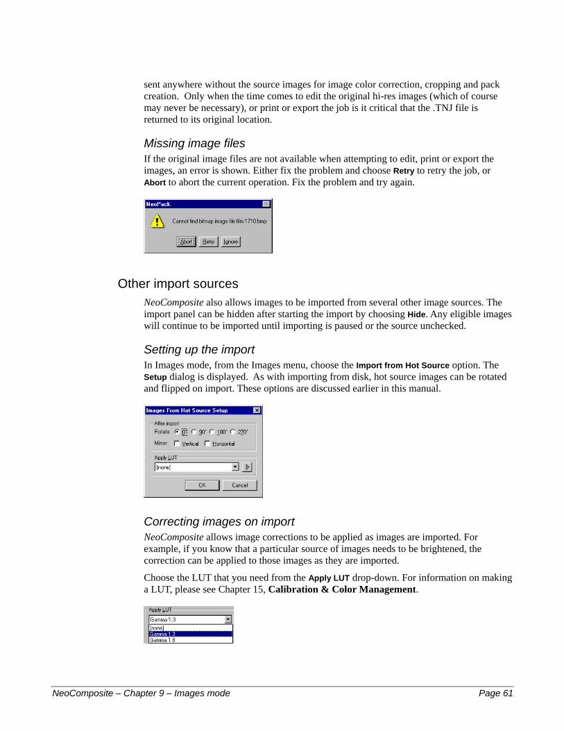
sent anywhere without the source images for image color correction, cropping and pack creation. Only when the time comes to edit the original hi-res images (which of course may never be necessary), or print or export the job is it critical that the .TNJ file is returned to its original location.
Missing image files If the original image files are not available when attempting to edit, print or export the images, an error is shown. Either fix the problem and choose Retry to retry the job, or Abort to abort the current operation. Fix the problem and try again.
Other import sources NeoComposite also allows images to be imported from several other image sources. The import panel can be hidden after starting the import by choosing Hide. Any eligible images will continue to be imported until importing is paused or the source unchecked.
Setting up the import In Images mode, from the Images menu, choose the Import from Hot Source option. The Setup dialog is displayed. As with importing from disk, hot source images can be rotated and flipped on import. These options are discussed earlier in this manual.
Correcting images on import NeoComposite allows image corrections to be applied as images are imported. For example, if you know that a particular source of images needs to be brightened, the correction can be applied to those images as they are imported.
Choose the LUT that you need from the Apply LUT drop-down. For information on making a LUT, please see Chapter 15, Calibration & Color Management.
NeoComposite – Chapter 9 – Images mode Page 61

Importing from the Windows clipboard If your have an application or scanner that can place the images into the Windows clipboard, NeoComposite can import these images directly.
Choose Images, Import from hot source… The Import from hot source dialog opens. Make sure Clipboard is checked, and Pause importing is unchecked. Any images that appear in the Windows clipboard will be inserted to the currently open file. The images are inserted according to the options set in the Options panel as previously discussed.
Importing from Kinetic bitmap devices Some other imaging applications use this method as an image interchange. If your device is compatible, images will be inserted automatically according to the settings made in the Options panel. If you’re not sure if your device is compatible, check with Timestone Software.
Figure 9: The Images from hot source panel
Figure 10: Import panel with indexed images
Editing images while importing As mentioned earlier, it is possible to have certain operations performed on images while they are being imported. You can’t zoom or crop while importing, but you can sharpen, rotate and color correct (using a pre-existing LUT) while images are being imported. During the import operation, the editing operation is not as responsive as it would normally be, and we recommend that you use the keyboard to perform the edits.
The image import can still be controlled, even though you may have hidden the main image import dialog by choosing the Hide button. Open the Import options panel by choosing Images, Import options panel…. This small panel can be positioned on the screen so the image import can be paused or restarted.
NeoComposite – Chapter 9 – Images mode Page 62
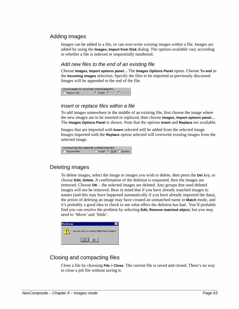
Adding images Images can be added to a file, or can over-write existing images within a file. Images are added by using the Images, Import from Disk dialog. The options available vary according to whether a file is indexed or sequentially numbered.
Add new files to the end of an existing file Choose Images, Import options panel… The Images Options Panel opens. Choose To end as the Incoming images selection. Specify the files to be imported as previously discussed. Images will be appended to the end of the file.
Insert or replace files within a file To add images somewhere in the middle of an existing file, first choose the image where the new images are to be inserted or replaced, then choose Images, Import options panel… The Images Options Panel is shown. Note that the options Insert and Replace are available.
Images that are imported with Insert selected will be added from the selected image. Images imported with the Replace option selected will overwrite existing images from the selected image.
Deleting images To delete images, select the image or images you wish to delete, then press the Del key, or choose Edit, Delete. A confirmation of the deletion is requested, then the images are removed. Choose OK – the selected images are deleted. Any groups that used deleted images will not be removed. Bear in mind that if you have already matched images to names (and this may have happened automatically if you have already imported the data), the action of deleting an image may have created an unmatched name in Match mode, and it’s probably a good idea to check to see what effect the deletion has had. You’ll probably find you can resolve the problem by selecting Edit, Remove matched object, but you may need to ‘Move’ and ‘Slide’.
Closing and compacting files Close a file by choosing File > Close. The current file is saved and closed. There’s no way to close a job file without saving it.
NeoComposite – Chapter 9 – Images mode Page 63

Images are stored in NeoComposite’s database type file. As images are deleted in the program, they are not physically removed from the file, although they are no longer available. One result of this is that the file size will remain the same, even if images are deleted from the file.
The deleted image space can be ‘freed up’ by choosing File, Close & Compact. This process may take a little time to perform, and also requires some hard disk space (at least as much as the new file’s size). Once done, the file will only contain the essential image data, and be as small as possible.
It is recommended that a file is compacted after many images have been deleted, or before being archived.
Correcting, editing and displaying images After the images have been imported, you can correct them using NeoComposite’s zoom, crop, color density and contrast controls. You can also control how the images are displayed on-screen while you perform these operations.
If you have specified an external image editor via File, Options (see Chapter 6, Configuring NeoComposite), you can also open individual images in another application and perform edits such as taking out spots that may have been introduced in the scanning process (or exist for any other reason!)
You can do this whether you imported the original high-res images into the NeoComposite job file or simply imported preview versions, referencing the high-res originals but not actually including them in the job file (see Images, importing, for a discussion of the advantages and disadvantages of doing either).
The editing process is much the same either way, but there are a couple of subtle differences.
Image editing To edit an image, you must be in Images mode, and you must have one image selected. If you have none or multiple selected, the menu option will be unavailable.
Choose Images, Edit image. The application you specified in File, Options will load, with the high-res version of the image loaded.
• If you imported the original high-res images into the NeoComposite job file, the file will appear as a .tif file, no matter what the original file format was. The TIF format, of course, is an uncompressed format, so you can make as many edits as you want and save as many times as you wish without degrading the image. If you were to do this with a .jpg image file, it would degrade slightly each time you saved it.
NeoComposite – Chapter 9 – Images mode Page 64

• If you imported preview versions, referencing the high-res originals but not actually including them in the job file, the original file will load, whatever format that happened to be. Thus, if it’s a .jpg file, bear in mind that each save will degrade the image slightly. If you’re likely to be saving the image more than a couple of times, we recommend saving it as a TIF or 24-bit BMP file while editing. If you do this, don’t forget to save it back to its original file type when you’re finished, as this is the only version of the file that NeoComposite will recognise.
Back in NeoComposite, you’ll see the following message:
Clicking the Continue button is NeoComposite’s signal to create and display a new preview image based on the original you’ve just modified. You should notice a change in the preview image as soon as you click that Continue button.
Changing the number of images displayed You can control the number of images displayed on-screen using the image pane controls. These are located at the bottom of the image preview pane.
Image set controls Choose the number of images you wish to display using the controls:
Choosing Single Image changes the image display to a single image. #
# Choosing Multiple Images changes the image display to the image table.
Single image Multiple images
Lock display
Number of images
Clicking the Number of images button (the third one of the four) pops up a sizeable grid. Moving the mouse increases or decreases the number of images displayed in the image
NeoComposite – Chapter 9 – Images mode Page 65

table. The grid will reflect whatever is currently displayed and you can increase or decrease this by holding down the left mouse button and moving the mouse. Whatever the grid displays when you release the mouse button will be what you end up with, but of course you can change it at any time. Or you can effect no change by pressing the ESC key before releasing the mouse button.
Correcting Images Once images have been imported to NeoComposite, they can be corrected in various ways:
Zoom #
#
#
#
#
Jog (x-y movement) Color and density corrections Image contrast corrections Image editing via an external image editor
There are many shortcuts available to achieve the various corrections, as are there many different ways to change the size and number of images being displayed.
Selecting images It is fast and convenient to select and navigate through images in the image table. First, choose an image by clicking on it with the mouse.
Action Keyboard Mouse
Select the first image Press the Home key
Select the last image Press the End key
Show the next screen of images
Press the Page Down key Use the scroll wheel
Show the next screen of images
Press the Page Down key Use the scroll wheel
Move to the Left image Press the Left arrow key
Move to the Right image Press the Right arrow key
Move to the image above Press the Up arrow key
Move to the image below Press the Down arrow key
Images can be moved and re-sized to create the best cropping for various aspect ratio prints. When in cropping mode, NeoComposite displays any enabled aspect ratios. Positioning should be adjusted so that images will appear pleasingly cropped at each of the different aspect ratios.
There are many different ways to zoom and crop images. Zoom and crop values are displayed in the Image Corrections palette. If the Image Corrections palette isn’t currently open, choose View, Image Corrections. Choose the image crop editing mode by choosing Images, Select crop & scale image tool.
NeoComposite – Chapter 9 – Images mode Page 66

Note that all images displayed in the image table now show the enabled aspect ratios.
Cropping images Choose an image. The image can be moved by:
Action Keyboard Mouse Image Correction palette
Move an image left
Hold the Control key and press the $ key
Click and drag the mouse
Click inside the ‘X’ value box, or Press <Control><X>. Decrease the value or press the % key
Move an image right
Hold the Control key and press the & key
Click and drag the mouse
Click inside the ‘X’ value box, or Press <Control><X>. Increase the value or press the ' key
Move an image up
Hold the Control key and press the ' key
Click and drag the mouse
Click inside the ‘Y’ value box, or Press <Control><Y>. Decrease the value or press the % key
Move an image down
Hold the Control key and press the % key
Click and drag the mouse
Click inside the ‘X’ value box, or Press <Control><Y>. Increase the value or press the ' key
Zooming images Choose an image. The image can be zoomed by:
Action Keyboard Mouse Image Correction palette
Make the image larger
Hold the Control key and press the Page Down key
Hold Control key and turn the scroll wheel or, hold the Shift key down and move the mouse up
Click inside the ‘S’ value box, or Press <Control> <S>. Decrease the value or press the % key
Make the image smaller
Hold the Control key and press the Page Up key
Hold Control key and turn the scroll wheel or,
Hold Shift key down and move the mouse down
Click inside the ‘S’ value box, or Press <Control> <S>. Increase the value or press the ' key
Moving images outside the image area It is possible to move the images outside the image area. This might cause white borders in the finished packages. If you move an image too far, indicators will appear to let you know that the image has been moved too far. The effect of this is that you will have unwanted white space around the image when you form packs for printing.
Zooming and jogging in practice Adjusting the size and position of images for the various print sizes to be printed is a most important task. If many images are to be adjusted, it is important to perform the task as quickly and accurately as possible.
Out of image area indicators
NeoComposite – Chapter 9 – Images mode Page 67

In practice, some operators will prefer to use the keyboard to make these adjustments, others will prefer to use the mouse and keyboard.
Using the mouse and keyboard Select the image to be corrected #
#
#
#
#
!
Hold the Control key down and use the scroll wheel to zoom the image. Release the Control key, click and drag the mouse to adjust the image position. Click the next image and repeat the operation. When you need to see the next screen of images, turn the scroll wheel.
Note that the control panels associated with scrolling mice often allow the scroll wheel to move a certain number of lines ‘per click’. You should set it to suit your needs. If the scroll wheel is set to ‘1 line’, the image table is moved 1 row per ‘click’. If it is set to 3 lines, the image table is moved by 3 rows per ‘click’.
Using the keyboard #
#
#
#
#
#
hether
correction palette can be operated ,
field t
one
s situation, there are a number of shortcut
Select the first image by pressing the Home key. Choose the image to be adjusted with the Arrow keys. Hold the Control key down and use the Arrow keys to move the image. Hold the Control key down and use the Page Up or Page Down keys to zoom the image. Use the Arrow keys to choose the next image to be edited. Use the Page Up or Page Down keys to see the next or previous page of images.
Adjusting the image color, density and contrast Image color, density and contrast can be changed using the image density controls. The corrections can be applied across a group of images, or individually. It all depends wyou have one image selected, or multiple.
The Image
Crop/Scale reset button
Color correction reset buttonwith the mouse by clicking in the desired field
then using the ‘spin’ controls next to each to increment the values. If you want to resevalues to zero, there are two reset buttons, for the crop/scale settings and another for the color settings, as shown at right.
If you find it cumbersome using the mouse in thi
Spin controls
keys available:
NeoComposite – Chapter 9 – Images mode Page 68
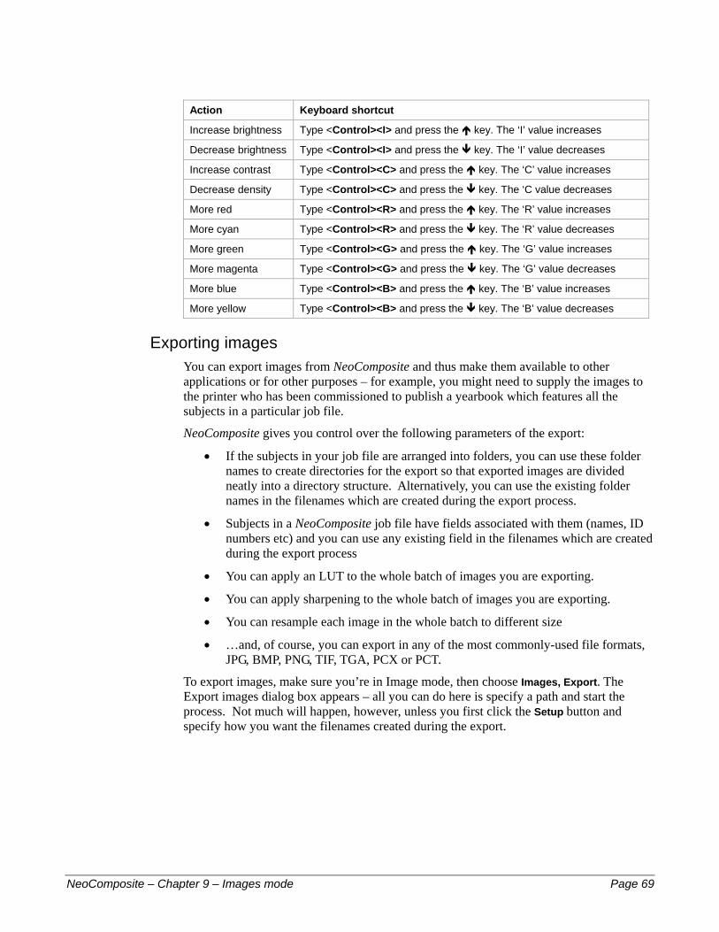
Action Keyboard shortcut
Increase brightness Type <Control><I> and press the ' key. The ‘I’ value increases
Decrease brightness Type <Control><I> and press the % key. The ‘I’ value decreases
Increase contrast Type <Control><C> and press the ' key. The ‘C’ value increases
Decrease density Type <Control><C> and press the % key. The ‘C value decreases
More red Type <Control><R> and press the ' key. The ‘R’ value increases
More cyan Type <Control><R> and press the % key. The ‘R’ value decreases
More green Type <Control><G> and press the ' key. The ‘G’ value increases
More magenta Type <Control><G> and press the % key. The ‘G’ value decreases
More blue Type <Control><B> and press the ' key. The ‘B’ value increases
More yellow Type <Control><B> and press the % key. The ‘B’ value decreases
Exporting images You can export images from NeoComposite and thus make them available to other applications or for other purposes – for example, you might need to supply the images to the printer who has been commissioned to publish a yearbook which features all the subjects in a particular job file.
NeoComposite gives you control over the following parameters of the export:
• If the subjects in your job file are arranged into folders, you can use these folder names to create directories for the export so that exported images are divided neatly into a directory structure. Alternatively, you can use the existing folder names in the filenames which are created during the export process.
• Subjects in a NeoComposite job file have fields associated with them (names, ID numbers etc) and you can use any existing field in the filenames which are created during the export process
• You can apply an LUT to the whole batch of images you are exporting.
• You can apply sharpening to the whole batch of images you are exporting.
• You can resample each image in the whole batch to different size
• …and, of course, you can export in any of the most commonly-used file formats, JPG, BMP, PNG, TIF, TGA, PCX or PCT.
To export images, make sure you’re in Image mode, then choose Images, Export. The Export images dialog box appears – all you can do here is specify a path and start the process. Not much will happen, however, unless you first click the Setup button and specify how you want the filenames created during the export.
NeoComposite – Chapter 9 – Images mode Page 69
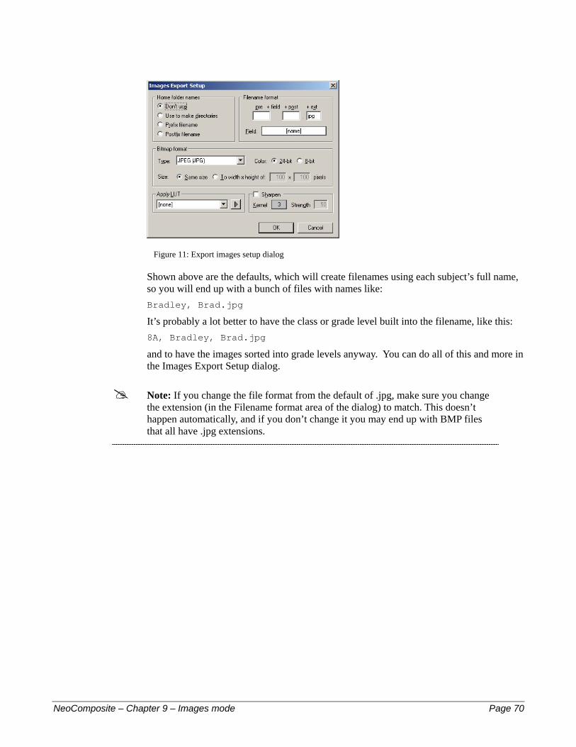
Figure 11: Export images setup dialog
Shown above are the defaults, which will create filenames using each subject’s full name, so you will end up with a bunch of files with names like: Bradley, Brad.jpg
It’s probably a lot better to have the class or grade level built into the filename, like this: 8A, Bradley, Brad.jpg
and to have the images sorted into grade levels anyway. You can do all of this and more in the Images Export Setup dialog.
! Note: If you change the file format from the default of .jpg, make sure you change the extension (in the Filename format area of the dialog) to match. This doesn’t happen automatically, and if you don’t change it you may end up with BMP files that all have .jpg extensions.
NeoComposite – Chapter 9 – Images mode Page 70

10 –
NeoCom
10
Matching images and namesThe products created with NeoComposite generally have subject portraits matched to names. For this reason, it is necessary to go through a matching process where the names are matched to the images.
This process is done in Match mode, although it’s possible that you won’t need to do any matching because it will already have been done automatically when you imported the data (assuming you imported the images first, i.e. the images were already there). This way, all you need to use Match mode for is to check through the names and images to make sure that there are no inconsistencies.
Using Match mode To reach NeoComposite’s Match screen, choose Mode, Match.
The Match screen is divided to several sections:
The image/match preview area #
#
#
#
Look-up tools Search tools Match toolbar
The Match toolbar
Look-up tools
Image/match preview area
Search tools
Figure 12: Match mode
posite – Chapter 10 – Matching images and names Page 71

Matching – overview The process of matching images and names can be done in several ways – depending on your particular system and usual method of working.
Timestone CapturePost digital capture module If you use Timestone’s CapturePost, all the images will be pre-matched before they reach the lab. No matching is required aside from confirming the data.
Pre-matched data You might have an external system that matches images and names. This data can be imported and checked in the Match.
Matching via ‘Camera cards’ If you have a system where ID numbers are super-imposed onto the images, you can match manually using this information. NeoComposite provides a facility to enlarge the lower quarter of the image (where this information is likely to be), thus making it easier to match each image against the corresponding data. Simply select View, Camera Cards and then follow the steps as per Matching manually, below.
Matching via shoot cards If you have the name data before photography day, you might create Shoot cards with barcodes printed on them. Each subject is handed their card, and as they are photographed, the card is collected. If the subject is photographed several times, the card is marked with that number. Back in the lab, the shoot cards (which are in shoot order) are read with a barcode reader to insert them to the Match table.
Matching manually If you collect the shoot order from the order bags – which are collected in shoot order and marked with the number of times a subject was photographed – you can manually match. Choose the image, start typing the name and then select the name from the list.
As discussed in Chapter 8, Details mode, name data can be imported, and if match information (i.e. an ID number) is included in the data, the names can be matched to images on import, assuming you've already imported the images.
There are two types of data you can import or enter:
Name and group data – no matching information #
# Name, Data and match – the shoot order has been captured at photography time
You should consult Chapter 8, Details mode, for further information. Once the data has been imported, it will either be broadly matched (i.e. requiring some adjustments), or there will be no matching at all.
NeoComposite – Chapter 10 – Matching images and names Page 72

Matching from Shoot cards or order bags When matching from shoot cards or order bags, you are entering the shoot order to match the imported images – which are also in shoot order. Whether you use shoot cards with a barcode or type the name, the procedure is fundamentally the same.
Using the Match tools The Match interface is divided into several sections. The Look-up section lets you search for names and match them to the current image.
The Find section lets you find a particular image number or name.
The Match toolbar lets you adjust the positions and jog the images and names in a match.
Move / Move / Slide / Slide
Difference between Move and Slide The difference between the Move and Slide tools is that Move will move the image currently under the cursor, whereas the Slide tool will always slide the matched names – assuming there are unlocked images in the table. For example, in this row, if we slide or move the match up by a couple of images, the result is very similar – the names from the insertion point are moved up.
NeoComposite – Chapter 10 – Matching images and names Page 73
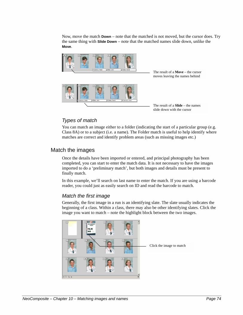
Now, move the match Down – note that the matched is not moved, but the cursor does. Try the same thing with Slide Down – note that the matched names slide down, unlike the Move.
The result of a Move – the cursor moves leaving the names behind
The result of a Slide – the names slide down with the cursor
Types of match You can match an image either to a folder (indicating the start of a particular group (e.g. Class 8A) or to a subject (i.e. a name). The Folder match is useful to help identify where matches are correct and identify problem areas (such as missing images etc.)
Match the images Once the details have been imported or entered, and principal photography has been completed, you can start to enter the match data. It is not necessary to have the images imported to do a ‘preliminary match’, but both images and details must be present to finally match.
In this example, we’ll search on last name to enter the match. If you are using a barcode reader, you could just as easily search on ID and read the barcode to match.
Match the first image Generally, the first image in a run is an identifying slate. The slate usually indicates the beginning of a class. Within a class, there may also be other identifying slates. Click the image you want to match – note the highlight block between the two images.
Click the image to match
NeoComposite – Chapter 10 – Matching images and names Page 74

The first image is a slate, indicating the beginning of class 8A. We will match the slate to the 8A folder.
! Note: This ‘preliminary match’ is only for convenience and assisting identifying problems in the match. You should always start by matching slates to miscellaneous items (like slates) – preferably matching to a folder.
Make sure that the Lookup-via Fields for folders option (top left, just under the toolbar) is set to name, then click in the Match image with folder entry box and start typing the name of the group. As you type, the matching items are displayed. Choose the correct item and press the Enter key. The image is matched to that folder and the Match cursor advances to the next image.
Match the next image The next image belongs to Sandra McAlister. In the for subjects drop-down, select Lastname as the Look-up field (or ID if you’re using a barcode reader). Start typing the last name. Note that as you type more characters for the name the list of choices is refined. Click on the desired name (or highlight it and press Enter) to match the name with the currently-selected image – the match is displayed and the Match bar advances to the next image.
Coping with errors You may find that the match gets out of synch sometimes. You might notice that you are matching a male name to an image that is obviously a female, or have too many bags to match to too few images. This usually happens if images are missing, or the shoot order is somehow incorrect. If you notice that you are incorrectly matching, return to the last known correctly-matched image – usually a slate.
Lock a match If you can locate a match that you know is correct, you can lock the match. When you lock an image, any matches before the match will stay unaltered if you ‘Move’ or ‘Slide’. You can lock an image by choosing the image to
NeoComposite – Chapter 10 – Matching images and names Page 75

lock, then choose Edit, Lock/unlock match or type Ctrl-L or click the Lock/unlock button in the toolbar. The image will be locked to the current match.
The Lock bar indicating the match is locked
Adjusting a match You might find that your raw match has a number of errors. In the following example, the film scanner has scanned a number of extra images, and a slate that isn’t included in the match. Each of these problem images has been matched to a subject, meaning that the match will be wrong from this point on. NeoComposite lets you adjust the match using a ‘Move’ and ‘Slide’ of the names and images. If you move an image, you move the current image up or down while the names stay put. If you slide the names, you slide all the names up and down while the images stay put.
! Note: The names and images are both really just sequential lists, irrespective of whether they are displayed in three rows of four, or six rows of five, etc. It might help if you bear this in mind when moving images or names!
How the names and images move depends on what has been locked previously.
Moving and sliding an unlocked table Moving or sliding the match has very different effects on the match table. Think of the move as an overall ‘bump’ that will bump things up or down. Sliding will only slide the names up or down.
Clicking the Move Down button moves or bumps the match down, exposing a blank.
NeoComposite – Chapter 10 – Matching images and names Page 76

Moving the match down reveals a blank
Clicking the Slide Down button moves the matched names down
Sliding the match down slides the names table down
Move the match When a match is moved, all matches are shifted up or down. The order of the match is not changed at all – it is simply shifted up or down. If a match has been locked, this might mean an image becomes un-matched, or a blank image may be inserted to maintain the relative match. In this example, we need to move the names below the problem images down to meet the correct image.
Choose Edit, Move up from selected, or type Ctrl <Right Arrow> or click Move Up in the toolbar 3 times. Note that the names are moved up from the selected point. Match the exposed board to folder 8B.
Move the match – effect on locked matches If you have locked a match, and need to slide or move the match, the result may be a blank image is inserted to the match table – perhaps an
NeoComposite – Chapter 10 – Matching images and names Page 77
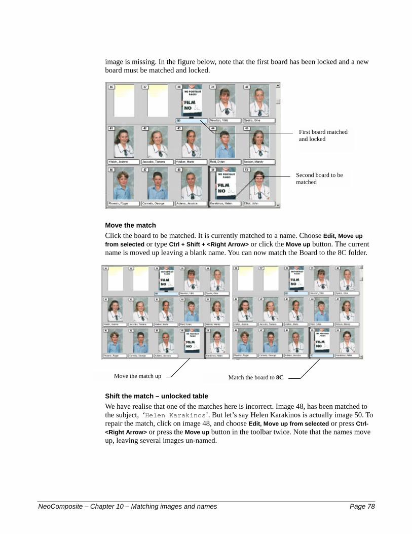
image is missing. In the figure below, note that the first board has been locked and a new board must be matched and locked.
First board matched and locked
Second board to be matched
Move the match Click the board to be matched. It is currently matched to a name. Choose Edit, Move up from selected or type Ctrl + Shift + <Right Arrow> or click the Move up button. The current name is moved up leaving a blank name. You can now match the Board to the 8C folder.
Move the match up Match the board to 8C
Shift the match – unlocked table We have realise that one of the matches here is incorrect. Image 48, has been matched to the subject, ‘Helen Karakinos’. But let’s say Helen Karakinos is actually image 50. To repair the match, click on image 48, and choose Edit, Move up from selected or press Ctrl-<Right Arrow> or press the Move up button in the toolbar twice. Note that the names move up, leaving several images un-named.
NeoComposite – Chapter 10 – Matching images and names Page 78
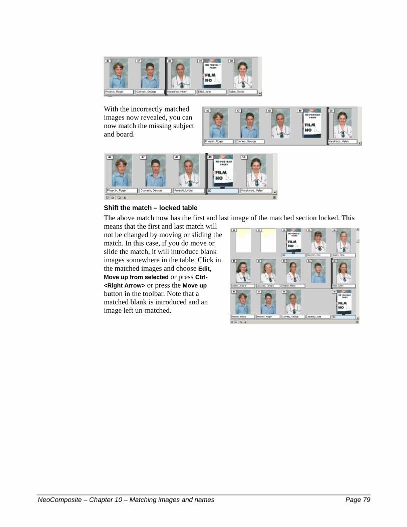
With the incorrectly matched images now revealed, you can now match the missing subject and board.
Shift the match – locked table The above match now has the first and last image of the matched section locked. This means that the first and last match will not be changed by moving or sliding the match. In this case, if you do move or slide the match, it will introduce blank images somewhere in the table. Click in the matched images and choose Edit, Move up from selected or press Ctrl-<Right Arrow> or press the Move up button in the toolbar. Note that a matched blank is introduced and an image left un-matched.
NeoComposite – Chapter 10 – Matching images and names Page 79
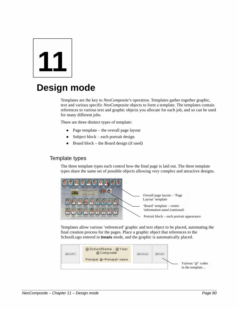
11 –
NeoCom
11
Design modeTemplates are the key to NeoComposite’s operation. Templates gather together graphic, text and various specific NeoComposite objects to form a template. The templates contain references to various text and graphic objects you allocate for each job, and so can be used for many different jobs.
There are three distinct types of template:
Page template – the overall page layout #
#
#
Subject block – each portrait design Board block – the Board design (if used)
Template types The three template types each control how the final page is laid out. The three template types share the same set of possible objects allowing very complex and attractive designs.
Templates allow various ‘referenced’ graphic and text object to be placed, automating the final creation process for the pages. Place a graphic object that references to the SchoolLogo entered in Details mode, and the graphic is automatically placed.
Overall page layout – ‘Page Layout’ template
‘Board’ template – centre ‘information panel (optional)
Portrait block – each portrait appearance
Various ‘@’ codes in the template…
posite – Chapter 11 – Design mode Page 80

Forms the finished page automatically
Template objects NeoComposite templates contain a number of special NeoComposite objects. These objects control how the portraits are positioned onto the page. They are:
Block area – controls where on the page the portraits will appear #
#
#
#
#
Protection area – causes an area to by un-obscured by portraits Unfeatured line –the unfeatured name list ‘Rotated’ portrait – places a larger individual portrait using the Block template Portrait block – places the rotated portrait, independent of the block template
Block area The block area defines where on the page the portrait images will appear. You can place more than one block area on a page and images will automatically flow between the blocks. Combining this with a cut mark lets you create split pages that flow a single composite group across several pages.
It is possible to define more than one block area per composite group. By adding a cut mark to the Page Layout template, you can create split pages, useful when creating composite pages with many images. You can also control the appearance of a centre board within a Block area, requesting that a board appear on any or all of the blocks defined – again useful if you are creating multi-page composite groups.
Protection area Your designs may have several areas in the graphic background that you want to be clear and un-obscured by portraits. Placing one or more protection areas onto the page in front of the Block area will cause the portraits to wrap around the protected areas.
NeoComposite – Chapter 11 – Design mode Page 81
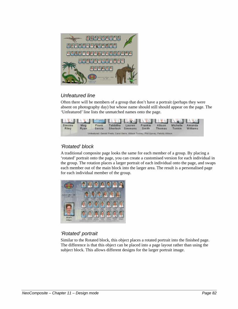
Unfeatured line Often there will be members of a group that don’t have a portrait (perhaps they were absent on photography day) but whose name should still should appear on the page. The ‘Unfeatured’ line lists the unmatched names onto the page.
‘Rotated’ block A traditional composite page looks the same for each member of a group. By placing a ‘rotated’ portrait onto the page, you can create a customised version for each individual in the group. The rotation places a larger portrait of each individual onto the page, and swaps each member out of the main block into the larger area. The result is a personalised page for each individual member of the group.
‘Rotated’ portrait Similar to the Rotated block, this object places a rotated portrait into the finished page. The difference is that this object can be placed into a page layout rather than using the subject block. This allows different designs for the larger portrait image.
NeoComposite – Chapter 11 – Design mode Page 82
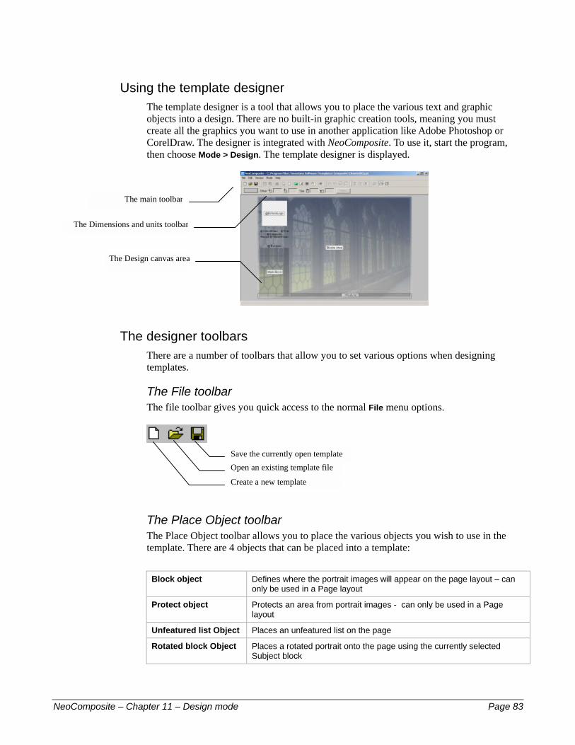
Using the template designer The template designer is a tool that allows you to place the various text and graphic objects into a design. There are no built-in graphic creation tools, meaning you must create all the graphics you want to use in another application like Adobe Photoshop or CorelDraw. The designer is integrated with NeoComposite. To use it, start the program, then choose Mode > Design. The template designer is displayed.
The main toolbar
The Dimensions and units toolbar
The designer toolbars There are a number of toolbars that allow you to set various options when designing templates.
The File toolbar The file toolbar gives you quick access to the normal File menu options.
The Place Object toolbar The Place Object toolbar allows you to place the various objects you wish to use in the template. There are 4 objects that can be placed into a template:
Block object Defines where the portrait images will appear on the page layout – can
only be used in a Page layout
Protect object Protects an area from portrait images - can only be used in a Page layout
Unfeatured list Object Places an unfeatured list on the page
Rotated block Object Places a rotated portrait onto the page using the currently selected Subject block
Create a new template
Open an existing template file Save the currently open template
The Design canvas area
NeoComposite – Chapter 11 – Design mode Page 83
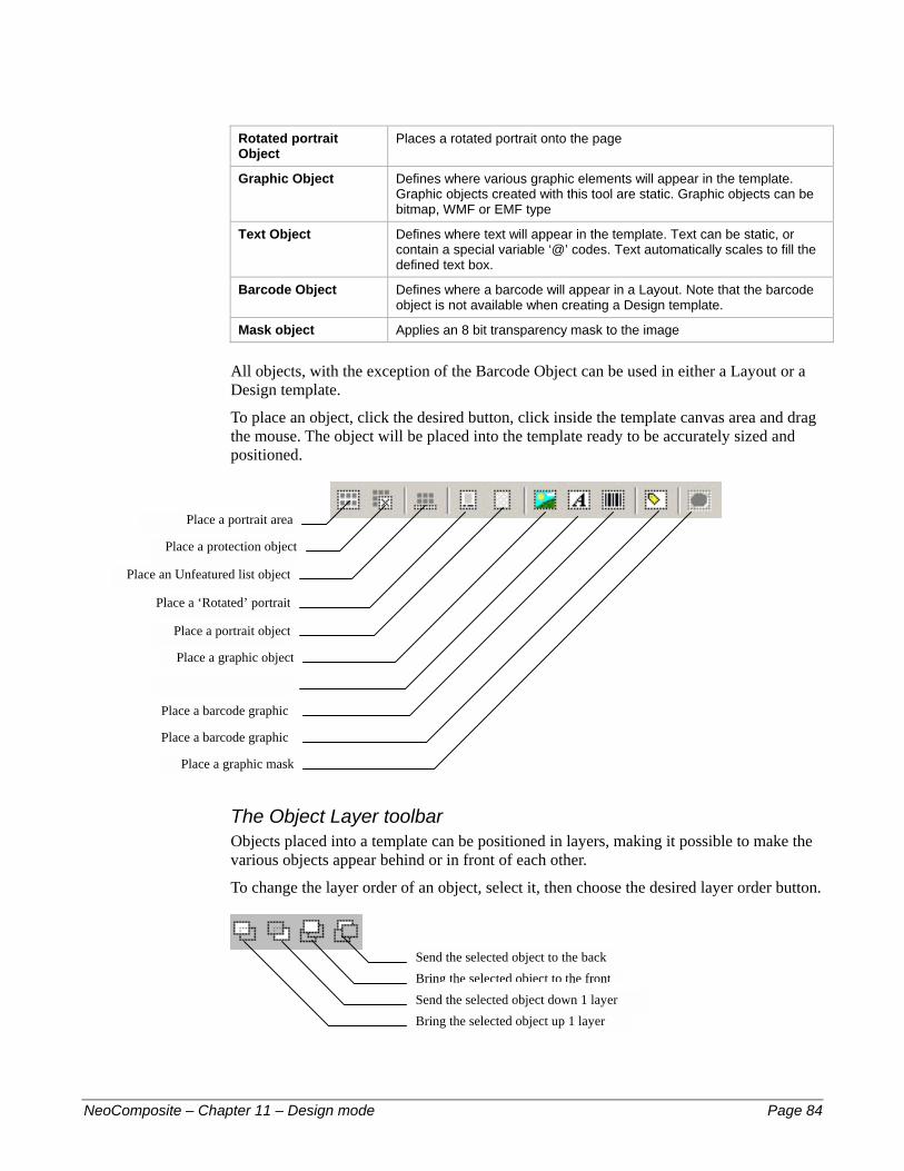
Rotated portrait Object
Places a rotated portrait onto the page
Graphic Object Defines where various graphic elements will appear in the template. Graphic objects created with this tool are static. Graphic objects can be bitmap, WMF or EMF type
Text Object Defines where text will appear in the template. Text can be static, or contain a special variable ‘@’ codes. Text automatically scales to fill the defined text box.
Barcode Object Defines where a barcode will appear in a Layout. Note that the barcode object is not available when creating a Design template.
Mask object Applies an 8 bit transparency mask to the image
All objects, with the exception of the Barcode Object can be used in either a Layout or a Design template.
To place an object, click the desired button, click inside the template canvas area and drag the mouse. The object will be placed into the template ready to be accurately sized and positioned.
Place a text object
Place a graphic object
Place an Unfeatured list object
Place a portrait area
Place a barcode graphic
Place a protection object
Place a ‘Rotated’ portrait
Place a portrait object
Place a barcode graphic
Place a graphic mask
The Object Layer toolbar Objects placed into a template can be positioned in layers, making it possible to make the various objects appear behind or in front of each other.
To change the layer order of an object, select it, then choose the desired layer order button.
Send the selected object to the back
Bring the selected object to the front
Bring the selected object up 1 layer Send the selected object down 1 layer
NeoComposite – Chapter 11 – Design mode Page 84
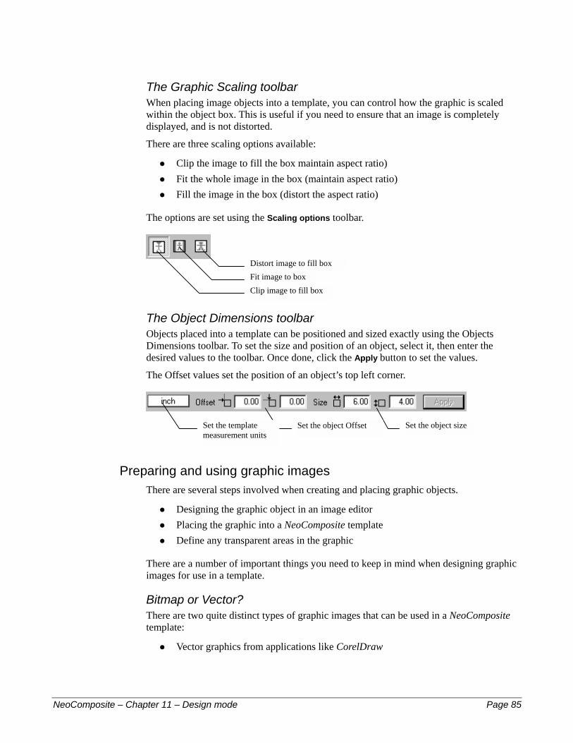
The Graphic Scaling toolbar When placing image objects into a template, you can control how the graphic is scaled within the object box. This is useful if you need to ensure that an image is completely displayed, and is not distorted.
There are three scaling options available:
Clip the image to fill the box maintain aspect ratio) #
#
#
Fit the whole image in the box (maintain aspect ratio) Fill the image in the box (distort the aspect ratio)
The options are set using the Scaling options toolbar.
Clip image to fill box
Distort image to fill box Fit image to box
The Object Dimensions toolbar Objects placed into a template can be positioned and sized exactly using the Objects Dimensions toolbar. To set the size and position of an object, select it, then enter the desired values to the toolbar. Once done, click the Apply button to set the values.
The Offset values set the position of an object’s top left corner.
Set the template measurement units
Set the object size Set the object Offset
Preparing and using graphic images There are several steps involved when creating and placing graphic objects.
Designing the graphic object in an image editor #
#
#
#
Placing the graphic into a NeoComposite template Define any transparent areas in the graphic
There are a number of important things you need to keep in mind when designing graphic images for use in a template.
Bitmap or Vector? There are two quite distinct types of graphic images that can be used in a NeoComposite template:
Vector graphics from applications like CorelDraw
NeoComposite – Chapter 11 – Design mode Page 85
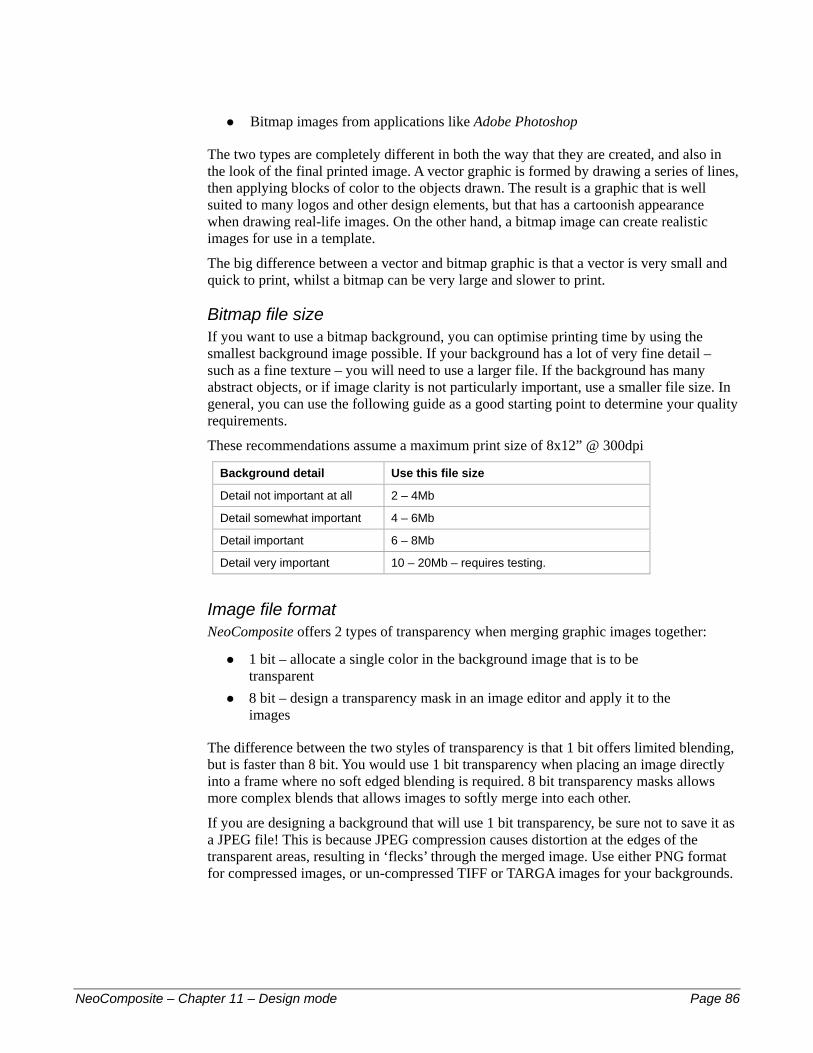
Bitmap images from applications like Adobe Photoshop #
The two types are completely different in both the way that they are created, and also in the look of the final printed image. A vector graphic is formed by drawing a series of lines, then applying blocks of color to the objects drawn. The result is a graphic that is well suited to many logos and other design elements, but that has a cartoonish appearance when drawing real-life images. On the other hand, a bitmap image can create realistic images for use in a template.
The big difference between a vector and bitmap graphic is that a vector is very small and quick to print, whilst a bitmap can be very large and slower to print.
Bitmap file size If you want to use a bitmap background, you can optimise printing time by using the smallest background image possible. If your background has a lot of very fine detail – such as a fine texture – you will need to use a larger file. If the background has many abstract objects, or if image clarity is not particularly important, use a smaller file size. In general, you can use the following guide as a good starting point to determine your quality requirements.
These recommendations assume a maximum print size of 8x12” @ 300dpi
Background detail Use this file size
Detail not important at all 2 – 4Mb
Detail somewhat important 4 – 6Mb
Detail important 6 – 8Mb
Detail very important 10 – 20Mb – requires testing.
Image file format NeoComposite offers 2 types of transparency when merging graphic images together:
1 bit – allocate a single color in the background image that is to be transparent
#
# 8 bit – design a transparency mask in an image editor and apply it to the images
The difference between the two styles of transparency is that 1 bit offers limited blending, but is faster than 8 bit. You would use 1 bit transparency when placing an image directly into a frame where no soft edged blending is required. 8 bit transparency masks allows more complex blends that allows images to softly merge into each other.
If you are designing a background that will use 1 bit transparency, be sure not to save it as a JPEG file! This is because JPEG compression causes distortion at the edges of the transparent areas, resulting in ‘flecks’ through the merged image. Use either PNG format for compressed images, or un-compressed TIFF or TARGA images for your backgrounds.
NeoComposite – Chapter 11 – Design mode Page 86
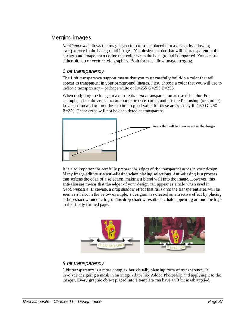
Merging images NeoComposite allows the images you import to be placed into a design by allowing transparency in the background images. You design a color that will be transparent in the background image, then define that color when the background is imported. You can use either bitmap or vector style graphics. Both formats allow image merging.
1 bit transparency The 1 bit transparency support means that you must carefully build-in a color that will appear as transparent in your background images. First, choose a color that you will use to indicate transparency – perhaps white or R=255 G=255 B=255.
When designing the image, make sure that only transparent areas use this color. For example, select the areas that are not to be transparent, and use the Photoshop (or similar) Levels command to limit the maximum pixel value for these areas to say R=250 G=250 B=250. These areas will not be considered as transparent.
Areas that will be transparent in the design
It is also important to carefully prepare the edges of the transparent areas in your design. Many image editors use anti-aliasing when placing selections. Anti-aliasing is a process that softens the edge of a selection, making it blend well into the image. However, this anti-aliasing means that the edges of your design can appear as a halo when used in NeoComposite. Likewise, a drop shadow effect that falls onto the transparent area will be seen as a halo. In the below example, a designer has created an attractive effect by placing a drop-shadow under a logo. This drop shadow results in a halo appearing around the logo in the finally formed page.
8 bit transparency 8 bit transparency is a more complex but visually pleasing form of transparency. It involves designing a mask in an image editor like Adobe Photoshop and applying it to the images. Every graphic object placed into a template can have an 8 bit mask applied.
NeoComposite – Chapter 11 – Design mode Page 87

Transparent areas in Vector graphics Vector graphics can contain areas that are a hole as a native part of their design. NeoComposite will reflect the hole in the design, allowing you to create transparent areas in a vector graphic as well as a bitmap.
How a hole is created in a vector depends on the drawing application you are using. For example, with CorelDraw, draw two objects of different color, and place them one on top of the other. Choose Arrange > Combine to combine the two objects. One of the objects will form a hole in the other.
Consult your applications user manual for more detailed information regarding combining objects for this effect.
Creating templates Once you have all the various components, you can design a new template. Start NeoComposite, and choose Mode > Design. The template designer is displayed. Now, choose File > New – the template type dialog opens. Choose the template type you wish to create and a new template is created. The procedures for placing the various objects are common for all three template types. The specific details required for each template type are covered after this general conversation.
NeoComposite – Chapter 11 – Design mode Page 88

Set the template page size Once the new layout screen is displayed, click on the background page. Note that the page handles become active.
When designing a layout, the actual final print size is being specified, so it is important to enter the correct page size. Note when the page is chosen, the Size entry area becomes active. First, ensure that you have the correct units selected by clicking the units drop-down. Now, enter the page size you wish to use, then Apply. The page size changes.
Figure 13: Selected background page with handles
Placing NeoComposite objects There are many different types of objects available for NeoComposite templates. Placing an object on the page positions it into a layer, allowing the various components to be placed either behind or in front of each other.
Understanding layers Layers play an important role when creating templates. Not only does a layer determine how two graphic layers – one over the other – will appear, but also how the portrait images will appear on screen.
Normally, portraits will fill the entire area of the block area placed onto a page. If you place another graphic or text area on top of the portrait area, the portraits will wrap around those objects. If you place the other objects behind the block area, the portraits will ignore the other objects and appear on top of them.
NeoComposite – Chapter 11 – Design mode Page 89
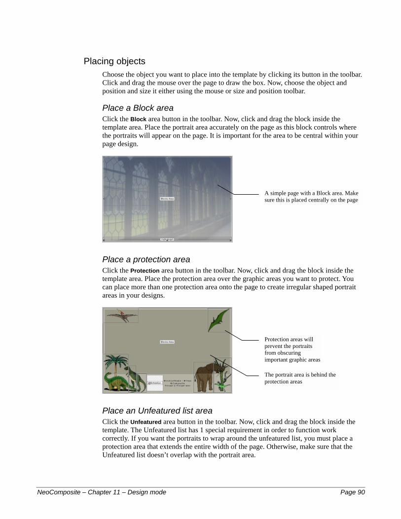
Placing objects Choose the object you want to place into the template by clicking its button in the toolbar. Click and drag the mouse over the page to draw the box. Now, choose the object and position and size it either using the mouse or size and position toolbar.
Place a Block area Click the Block area button in the toolbar. Now, click and drag the block inside the template area. Place the portrait area accurately on the page as this block controls where the portraits will appear on the page. It is important for the area to be central within your page design.
A simple page with a Block area. Make sure this is placed centrally on the page
Place a protection area Click the Protection area button in the toolbar. Now, click and drag the block inside the template area. Place the protection area over the graphic areas you want to protect. You can place more than one protection area onto the page to create irregular shaped portrait areas in your designs.
Protection areas will prevent the portraits from obscuring important graphic areas
The portrait area is behind the protection areas
Place an Unfeatured list area Click the Unfeatured area button in the toolbar. Now, click and drag the block inside the template. The Unfeatured list has 1 special requirement in order to function work correctly. If you want the portraits to wrap around the unfeatured list, you must place a protection area that extends the entire width of the page. Otherwise, make sure that the Unfeatured list doesn’t overlap with the portrait area.
NeoComposite – Chapter 11 – Design mode Page 90
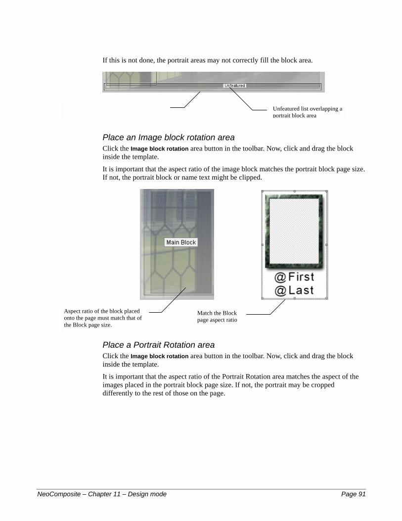
If this is not done, the portrait areas may not correctly fill the block area.
Unfeatured list overlapping a portrait block area
Protection area extending the width of thepage, overlapping the Unfeatured list
Place an Image block rotation area Click the Image block rotation area button in the toolbar. Now, click and drag the block inside the template.
It is important that the aspect ratio of the image block matches the portrait block page size. If not, the portrait block or name text might be clipped.
Aspect ratio of the block placed onto the page must match that of the Block page size.
Match the Block page aspect ratio
Place a Portrait Rotation area Click the Image block rotation area button in the toolbar. Now, click and drag the block inside the template.
It is important that the aspect ratio of the Portrait Rotation area matches the aspect of the images placed in the portrait block page size. If not, the portrait may be cropped differently to the rest of those on the page.
NeoComposite – Chapter 11 – Design mode Page 91

To that placed in the Block templates Match the aspect ratio of the
simple rotated portrait…
Placing graphic images Images can be placed anywhere in the template, and in layers. This allows you to place images behind and if front of one another, allowing complex and attractive images to be created. When an image is placed into the template, you can define the transparent area, as well as the size, position and image scaling options applied to the image.
Choose the Place graphic object button in the toolbar . The cursor changes to the Place Object cursor. Position the mouse over the area on the page where you want the hole to appear. Click and drag a box over the page. It is not important to be accurate at this point. A File Open dialog is displayed. Choose the file you wish to place and choose Open.
Figure 14: The file Open dialog to place a graphic object
The file is read, and the object appears in the template.
NeoComposite – Chapter 11 – Design mode Page 92

Set 1 bit transparency If the image you are using has a single color designed in it that should be transparent, set the transparent color here by clicking it in the preview. In this case, the white area in the lower left should be transparent.
Click the white area todefine the transparent color
Click the area and a grid pattern appears, indicating the area is transparent.
The grid pattern indicatesthe transparent area
Once the transparent area has been set, you will see the transparent area indicated by the grid pattern.
NeoComposite – Chapter 11 – Design mode Page 93

Figure 15: A placed graphic object
Positioning and sizing an object Click the object. Hold the CTRL key down if necessary (if several objects have already been placed).
Either click and drag one of the handles, or drag the object to scale and position of the object with the mouse. If you need more accurate placement, click the object, then enter an absolute origin and size in the Object Dimensions toolbar, then choose Apply. The object is positioned and sized exactly.
Placing images into 1 bit transparent areas The area in your design where the images you import are to appear is called a ‘hole’. As mentioned before, this area is defined by coloring the areas of the graphic a specific color. In this example, the area has been defined by pixels that are R=255 G=255 and B=255.
After the graphic has been placed and positioned, click the Image Object button . The mouse pointer changes the Place Object pointer. Click and drag the mouse over the template where you want the image to appear. It is not important to be accurate at this point.
When the object is placed, it will be sitting over the top of the background.
NeoComposite – Chapter 11 – Design mode Page 94

Figure 16: The Image Object placed over a Graphic Object
With the Image Object selected (the handles are visible), click the Send down 1 layer button. The Image Object is moved down 1 layer, and is now behind the transparent area of the Graphic Object. Note in the picture below that it is possible to see the full design, along with the whole name board.
Figure 17: Image Object moved behind name board
Applying an 8 bit transparency mask 8 bit masks can be applied to any graphic object placed onto a template. There are 2 types of graphic objects:
A bitmap image #
# A NeoComposite graphic object
Bitmap image transparency mask As previously discussed, click and drag a graphic image area on the page. Choose the file to place, and the Set Bitmap Mask dialog opens. Now, click From File… the Set Mask dialog opens. Click the Load button. A File > Open dialog opens. Locate and choose the mask file. Press Open.
NeoComposite – Chapter 11 – Design mode Page 95

A preview of the mask is shown. You can flip or rotate the mask if required. After you’re happy with the settings, choose OK. A preview of the masked image is shown. If you want to remove the mask file, click the Reset button. The mask is removed. Choose OK.
The masked image is placed into the template.
Placing additional graphic objects As many graphic objects as you need can be placed into a template. To add a further object, repeat the above process.
! If a graphic object that is placed over the top a hole has the transparent color, it will be merged is described above. Be sure that for objects that you don’t want to merge, you choose Cancel at the Set Bitmap Mask dialog.
NeoComposite – Chapter 11 – Design mode Page 96

Controlling image scaling When placing image objects into a template, you can control how the graphic is scaled within the object box. This is useful if you need to ensure that an image is completely displayed, and is not distorted.
There are three scaling options available:
Clip the image to fill the box maintain aspect ratio) #
#
#
Fit the whole image in the box (maintain aspect ratio) Fill the image in the box (distort the aspect ratio)
The options are set using the Scaling options toolbar.
Changing the scaling option After placing a graphic object, select it, then click the appropriate scaling button in the Scaling options toolbar.
Choosing Scales the image…
Clip the image to fill the box maintain aspect ratio)
Fit the whole image in the box (maintain aspect ratio)
Fill the image in the box (distort the aspect ratio)
Distort image to fill box
Fit image to box Clip image to fill box
NeoComposite – Chapter 11 – Design mode Page 97
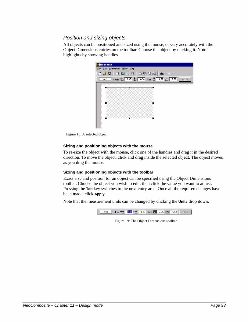
Position and sizing objects All objects can be positioned and sized using the mouse, or very accurately with the Object Dimensions entries on the toolbar. Choose the object by clicking it. Note it highlights by showing handles.
Figure 18: A selected object
Sizing and positioning objects with the mouse To re-size the object with the mouse, click one of the handles and drag it in the desired direction. To move the object, click and drag inside the selected object. The object moves as you drag the mouse.
Sizing and positioning objects with the toolbar Exact size and position for an object can be specified using the Object Dimensions toolbar. Choose the object you wish to edit, then click the value you want to adjust. Pressing the Tab key switches to the next entry area. Once all the required changes have been made, click Apply.
Note that the measurement units can be changed by clicking the Units drop down.
Figure 19: The Object Dimensions toolbar
NeoComposite – Chapter 11 – Design mode Page 98
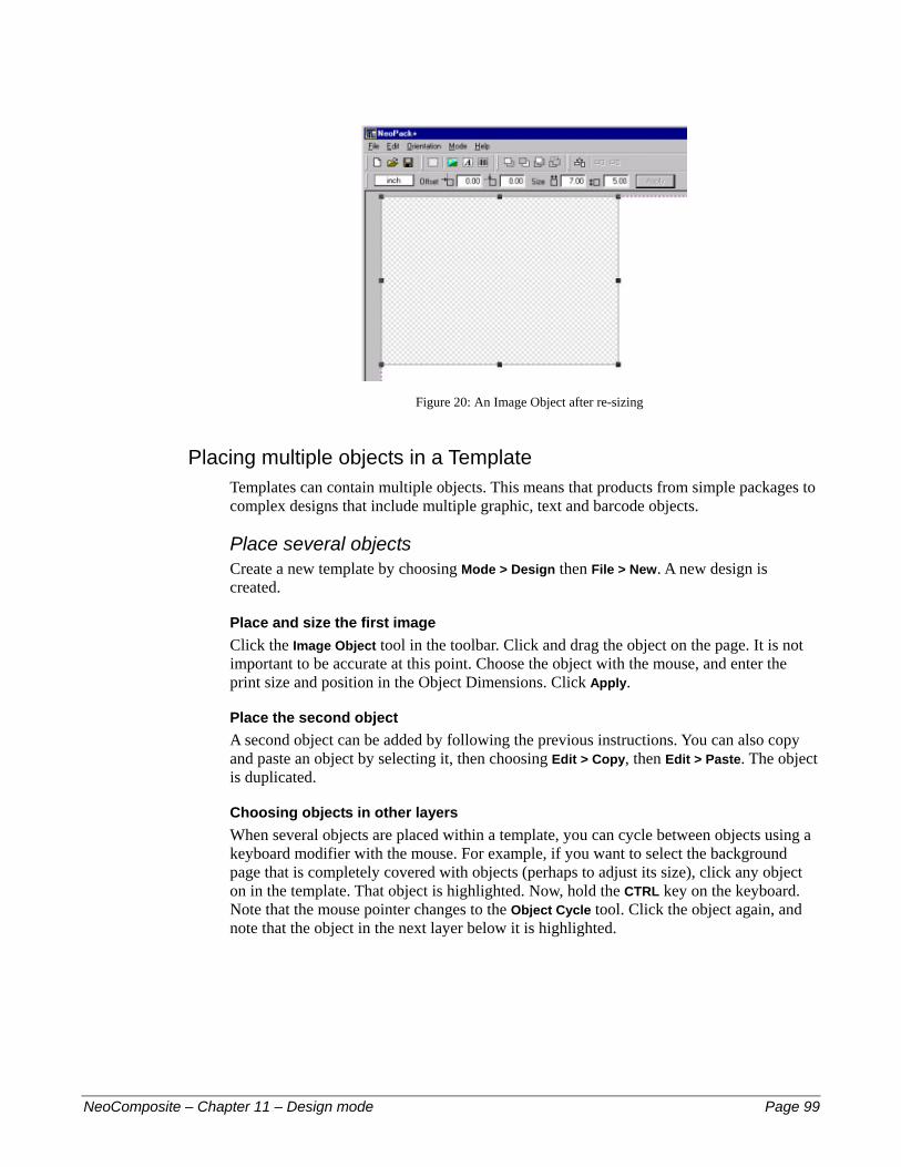
Figure 20: An Image Object after re-sizing
Placing multiple objects in a Template Templates can contain multiple objects. This means that products from simple packages to complex designs that include multiple graphic, text and barcode objects.
Place several objects Create a new template by choosing Mode > Design then File > New. A new design is created.
Place and size the first image Click the Image Object tool in the toolbar. Click and drag the object on the page. It is not important to be accurate at this point. Choose the object with the mouse, and enter the print size and position in the Object Dimensions. Click Apply.
Place the second object A second object can be added by following the previous instructions. You can also copy and paste an object by selecting it, then choosing Edit > Copy, then Edit > Paste. The object is duplicated.
Choosing objects in other layers When several objects are placed within a template, you can cycle between objects using a keyboard modifier with the mouse. For example, if you want to select the background page that is completely covered with objects (perhaps to adjust its size), click any object on in the template. That object is highlighted. Now, hold the CTRL key on the keyboard. Note that the mouse pointer changes to the Object Cycle tool. Click the object again, and note that the object in the next layer below it is highlighted.
NeoComposite – Chapter 11 – Design mode Page 99

Figure 21: Cycling between layer objects
Changing the layer order Objects can be positioned in front or behind each other. The order of the objects can be changed with the Object Order toolbar. The layer order of an object can be changed by selecting the object, then choosing a layer order tool in the toolbar.
Bring an object up 1 layer
Send an object down 1 layer
Send an object to the bottom layer
Bring an object to the top layer
Place two Image Objects on the page, and make sure that they overlap each other.
Figure 22: The selected object in the top layer
Click the Send down 1 layer tool. The selected object is sent down 1 layer, and will now appear behind the other in the finished print.
NeoComposite – Chapter 11 – Design mode Page 100

Figure 23: The selected object 1 layer lower
Using text objects Text objects in NeoComposite are a very powerful tool. Fixed text can be entered and stylised with font, style and color, appearing always the same in the final printed result. Text can also contain variable codes, allowing a template to pick data from the job file and automatically adding it to the printed job. This means that you can design templates that can be used for all your jobs, and have them customised automatically for each client. For example, a template might include a reference to the school’s name, principal name, and even an individual group teacher’s name. When the job is run, the data is fetched from the database and placed automatically into the printed job.
Fixed and variable text There are two types of text that can be placed in a template:
Fixed: The text appears the same in each job #
# Variable: The text changes for each image according to information entered for the image.
Variable text is defined using an ‘@’ symbol at the beginning of the text placed into the template. When NeoComposite sees the ‘@’ symbol, it looks to see if it has the necessary information for that image, and uses it if it does. If no information is available for the image, the ‘@’ code is ignored.
Placing text objects
Create a new template – either a Layout or a Design. Choose the Text Object tool from the toolbar. Click and drag over the template where you want the text to appear. The text entry dialog opens. Enter the text you want to appear in the template.
NeoComposite – Chapter 11 – Design mode Page 101

Figure 24: Text entry dialog box
Figure 25: Text placed into a template
Controlling text formatting Text – whether fixed or variable – can be stylised using font, color and style. To apply some text styling, choose the text you want to stylise, then choose the Font, size, style color or alignment from the Style Text toolbar.
Text scaling option
Font selection drop-down
Text size adjustment
Text colorText Style
Text alignment
Set the font Choose the text you wish to format, then choose the font from the drop-down dialog.
Set the style Choose the text you wish to format, then choose the font style from the available styles.
Set the alignment Choose the text you wish to format, then choose the alignment.
NeoComposite – Chapter 11 – Design mode Page 102

Controlling the text size By default, text will scale to fill the box you draw on the template. This ensures that any text that appears in a text box will never be clipped because it is too big. As you enter more text, the font size will reduce automatically.
Relative font size You can control the relative size of the text using the Relative scaling control. If you want some text to be bigger than the rest, select it, then click the Up or Down buttons in the Relative size entry box.
Variable text objects NeoComposite allows various data fields be defined for the various groups in your job. For example, there are some things that are common to a whole school such as the school name, year of photography and so on. It is then possible to gather the school’s groups into sub-categories. For example, the school might have a senior and junior campus. Years 1-7 belong to the junior school, 8-12 to the senior school. You can allocate a name to both the campuses, and have the correct campus name inserted to the name board for each particular year group.
Detail types As discussed in the previous chapters, Details mode and Image mode, it is possible to define and allocate various data fields to the folders in a job. There are three major details groupings:
‘File’ details – global information such as the school name, principal name etc.
#
#
#
‘Folder’ details – information specific to a folder or sub-folder such as the campus name, group teacher name etc. ‘Built-in’ details – built-in information that are pre-defined in NeoComposite. These include the composite name etc.
NeoComposite – Chapter 11 – Design mode Page 103
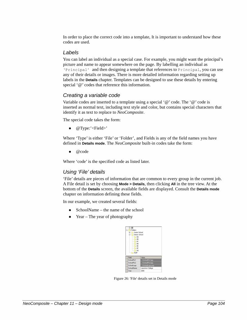
In order to place the correct code into a template, It is important to understand how these codes are used.
Labels You can label an individual as a special case. For example, you might want the principal’s picture and name to appear somewhere on the page. By labelling an individual as ‘Principal’ and then designing a template that references to Principal, you can use any of their details or images. There is more detailed information regarding setting up labels in the Details chapter. Templates can be designed to use these details by entering special ‘@’ codes that reference this information.
Creating a variable code Variable codes are inserted to a template using a special ‘@’ code. The ‘@’ code is inserted as normal text, including text style and color, but contains special characters that identify it as text to replace to NeoComposite.
The special code takes the form:
@Type:’<Field>’ #
#
#
#
Where ‘Type’ is either ‘File’ or ‘Folder’, and Fields is any of the field names you have defined in Details mode. The NeoComposite built-in codes take the form:
@code
Where ‘code’ is the specified code as listed later.
Using ‘File’ details ‘File’ details are pieces of information that are common to every group in the current job. A File detail is set by choosing Mode > Details, then clicking All in the tree view. At the bottom of the Details screen, the available fields are displayed. Consult the Details mode chapter on information defining these fields.
In our example, we created several fields:
SchoolName – the name of the school Year – The year of photography
Figure 26: 'File' details set in Details mode
NeoComposite – Chapter 11 – Design mode Page 104
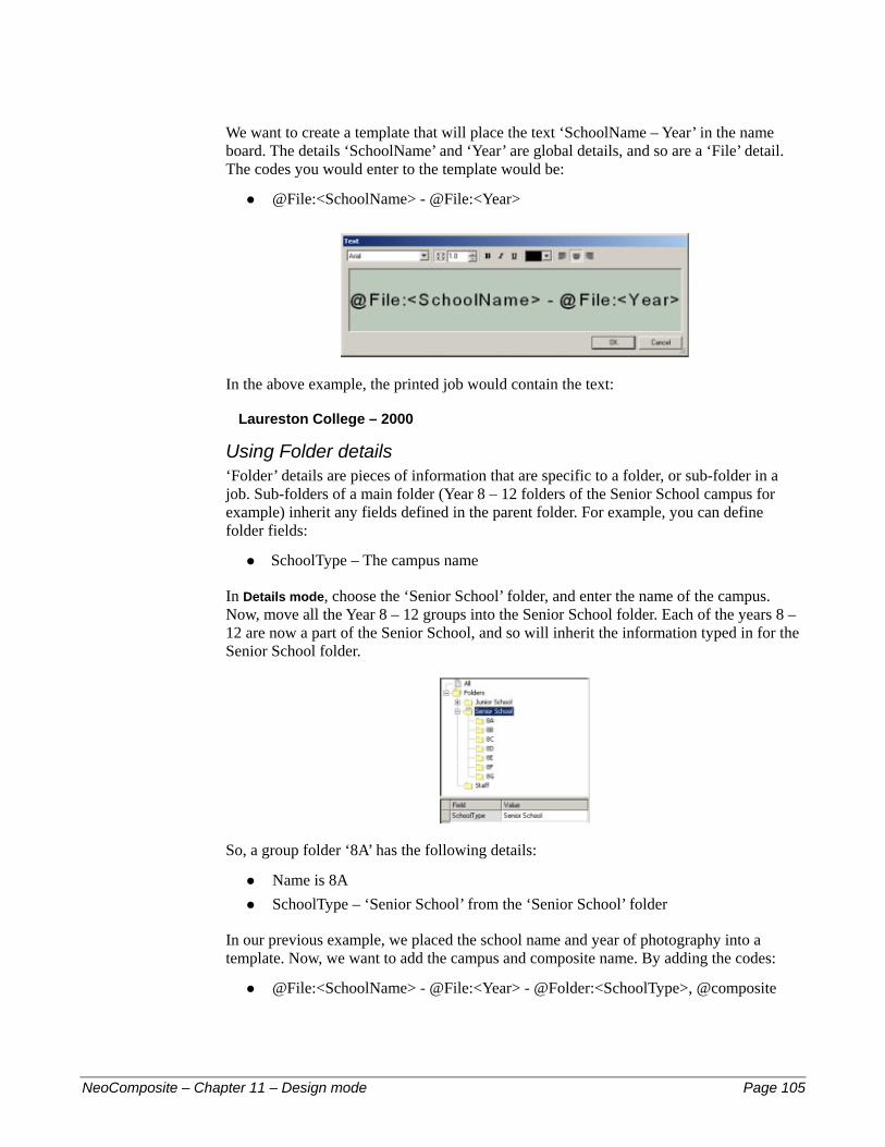
We want to create a template that will place the text ‘SchoolName – Year’ in the name board. The details ‘SchoolName’ and ‘Year’ are global details, and so are a ‘File’ detail. The codes you would enter to the template would be:
@File:<SchoolName> - @File:<Year> #
In the above example, the printed job would contain the text:
Laureston College – 2000
Using Folder details ‘Folder’ details are pieces of information that are specific to a folder, or sub-folder in a job. Sub-folders of a main folder (Year 8 – 12 folders of the Senior School campus for example) inherit any fields defined in the parent folder. For example, you can define folder fields:
SchoolType – The campus name #
In Details mode, choose the ‘Senior School’ folder, and enter the name of the campus. Now, move all the Year 8 – 12 groups into the Senior School folder. Each of the years 8 – 12 are now a part of the Senior School, and so will inherit the information typed in for the Senior School folder.
So, a group folder ‘8A’ has the following details:
Name is 8A #
#
#
SchoolType – ‘Senior School’ from the ‘Senior School’ folder
In our previous example, we placed the school name and year of photography into a template. Now, we want to add the campus and composite name. By adding the codes:
@File:<SchoolName> - @File:<Year> - @Folder:<SchoolType>, @composite
NeoComposite – Chapter 11 – Design mode Page 105

In the above example, the printed job would contain the text: Laureston College – 2000
Senior Campus, 8A
Using Labels Finally, we want to add the Principal’s details to the template. By labelling an individual as (for example) ‘Principal’ we can add these details. A label is added to an individual in Details mode.
Anne Galpin is labelled ‘Principal’
To add the Principal details, use a Label code. There are two types of code:
Matched image code – Uses the portrait image associated with the individual
#
# Text of Graphic Details code – Uses the value of a specific Details field, such as their name, ID number or even an attached graphic image
Label codes are constructed in this way:
Desired information Usage
Matched image @LabelName (i.e. @Principal)
Text or Graphic Details code @<LabelName>:DetailName
As an example, we want to design a template that will place a portrait image of the principal along with her name into a template.
Place the Matched image Click the Tagged object button in the toolbar and drag a box on the template. The Labeled Holder dialog opens. Enter the name of the label, @Principal and choose OK. Size and position the graphic box.
NeoComposite – Chapter 11 – Design mode Page 106
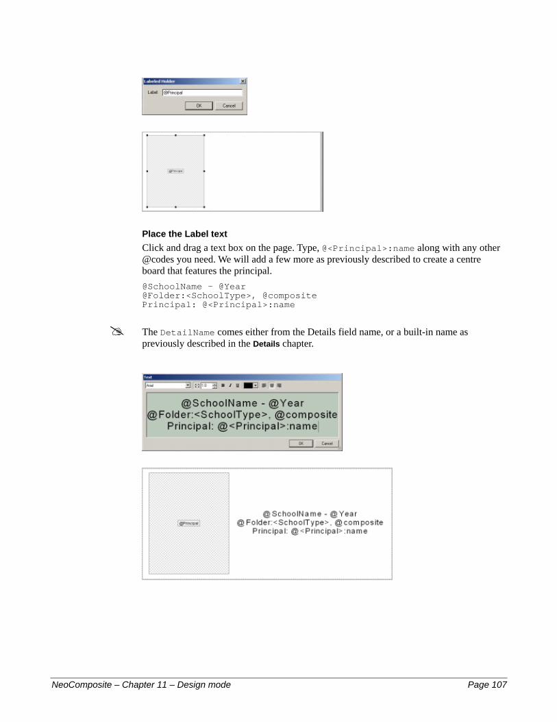
Place the Label text Click and drag a text box on the page. Type, @<Principal>:name along with any other @codes you need. We will add a few more as previously described to create a centre board that features the principal. @SchoolName - @Year @Folder:<SchoolType>, @composite Principal: @<Principal>:name
! The DetailName comes either from the Details field name, or a built-in name as previously described in the Details chapter.
NeoComposite – Chapter 11 – Design mode Page 107
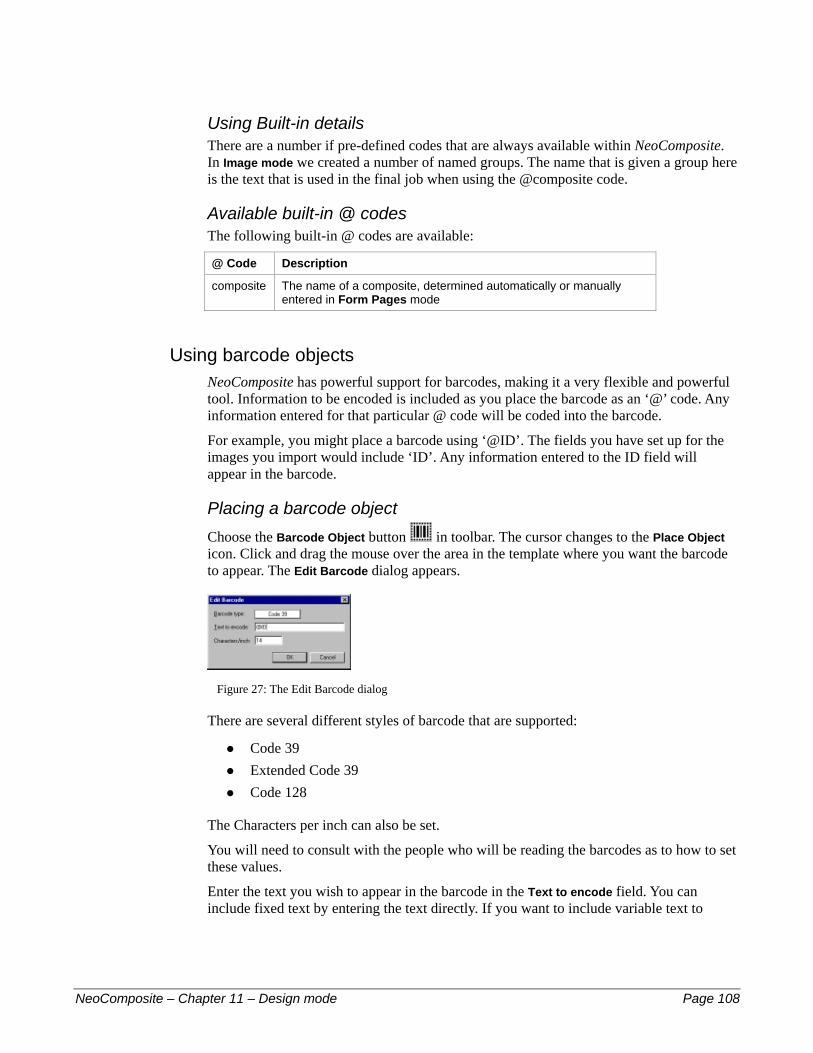
Using Built-in details There are a number if pre-defined codes that are always available within NeoComposite. In Image mode we created a number of named groups. The name that is given a group here is the text that is used in the final job when using the @composite code.
Available built-in @ codes The following built-in @ codes are available:
@ Code Description
composite The name of a composite, determined automatically or manually entered in Form Pages mode
Using barcode objects NeoComposite has powerful support for barcodes, making it a very flexible and powerful tool. Information to be encoded is included as you place the barcode as an ‘@’ code. Any information entered for that particular @ code will be coded into the barcode.
For example, you might place a barcode using ‘@ID’. The fields you have set up for the images you import would include ‘ID’. Any information entered to the ID field will appear in the barcode.
Placing a barcode object Choose the Barcode Object button in toolbar. The cursor changes to the Place Object icon. Click and drag the mouse over the area in the template where you want the barcode to appear. The Edit Barcode dialog appears.
Figure 27: The Edit Barcode dialog
There are several different styles of barcode that are supported:
Code 39 #
#
#
Extended Code 39 Code 128
The Characters per inch can also be set.
You will need to consult with the people who will be reading the barcodes as to how to set these values.
Enter the text you wish to appear in the barcode in the Text to encode field. You can include fixed text by entering the text directly. If you want to include variable text to
NeoComposite – Chapter 11 – Design mode Page 108

encode, add an ‘@’ code here. For example, ‘@ID’ to code the ‘ID’ data entered for an image.
Labeled Holders When you design your templates, you can place a ‘labeled holder’ on the page to simplify your production workflow. For example, you might want the current job’s logo to appear in the final image for each school you book. Rather than re-designing your templates to include each school’s individual logo, you can place a special box with a reference to the logo file. When you are creating the work for a particular school, you import the logo in Details mode. When the job is run, the logo is positioned in the design as specified by the template.
Creating and positioning a labeled holder To place a labeled holder, open the template you wish to use, then choose the Tagged
object button in the toolbar . Click and drag the mouse in the template where you want the object to appear. It is not necessary to be accurate. The Edit Attribute dialog is shown.
Entering the @ code Depending on how you create the jobs, you will have defined some default items in Details mode. In the previous example, we created graphic objects for the school logo, and the group teacher’s photographs. The ‘@’ Code is decided by the fieldname entered here. For example, ‘@SchoolLogo’ references the School’s logo, and ‘@TeacherPic’ references a group’s Teacher picture.
Labeled holders use the same naming as discussed in the Variable text objects section earlier in this chapter. Considering this naming procedure, the correct code for both these objects would be:
Object Code
SchoolLogo @File:<SchoolLogo>
TeacherPic @Folder:<TeacherPic>
NeoComposite – Chapter 11 – Design mode Page 109

Controlling Labeled holder scaling Images placed into a labeled holder can be scaled exactly as for a normally placed graphic. Choose the scaling you want to use by choosing the appropriate scaling from the toolbar.
Distort image to fill box
Clip image to fill boxFit image to box
Using the labeled graphic Labeled holders are fetched from Details mode. As discussed in the Details mode chapter, you can allocate various special graphic and text details:
File details – fields that are common to every folder and subject in the job. For example – a logo that is common for every group in the current job
#
#
#
#
#
#
#
Folder details – fields that are specific to a group or sub-grouping. For example, each class may have a mascot picture to be included, or a large school may be divided into ‘Junior’ and ‘Senior’ campuses.
Cut marks NeoComposite offers support for cutting templates into separate pages via cut marks. Cut marks are a flexible attribute set in a template. They will work with several different style of printer, including:
Roll to roll printers with either mid image or end/start of image punches Cut sheet printers without any punching system
For printers that support hole punches, you can define a number of cut mark positions within a pack. With our Windows NT Printer Drivers, the cut mark information is sent to the printer with the page being printed.
If your printer doesn’t support mid-image punching but has start or end of print punches, or is a cut-sheet printer, you can use cut marks to split the packs being printed. In this case, you can define a position to split the long pack. When the pack is printed, it will be sent to the printer split into a number of separate images. The result is either a punch at the beginning or end of each unit, or each unit will be printed individually.
Punch and printer types There are several types of digital printer available today:
Cut-sheet feed Long-roll, short length feed Long-roll, long length feed
NeoComposite – Chapter 11 – Design mode Page 110

A cut-sheet feed printer typically has a maximum paper advance. A good example is the Sienna FotoPrint range that typically has a maximum output size of 8x12" or 12x18" depending on the model.
A long-roll, short length feed printer is a roll to roll printer with easel mask. Again, these machines have a maximum possible paper advance. A good example is the Kodak MultiPrinter that has a maximum print size of 12x18".
A long-roll, long length feed printer is a roll to roll printer that has no maximum paper advance (aside from the paper roll length). This style of printer can create very long prints, in theory as long as the installed paper roll. A good example of this printer is the Sienna Mileca.
Cut-sheet or punching printers Cut-sheet printers typically don’t have a hole punching system built-in. Instead, they cut each individual print and process it immediately.
Punching printers are roll to roll style that usually punch either the beginning or end of a print. Once the roll of paper is processed, the prints are cut by your lab’s cutter into a stack of prints.
Additionally, some printers are able to punch the paper within a single print. You might be printing a series of packs that comprise 4 units per pack. This style printer can place a punch at the beginning of each unit in a pack as well as at the print start / end.
Hard and soft cut marks NeoComposite supports 2 types of cut mark:
Soft cut mark – the pack will be punched by the printer at the defined position
#
# Hard cut mark – NeoComposite will split the pack into separate pages at the defined position
In order to use soft cut marks, you must use a Timestone Software printer driver with a printer that supports mid-image punches. Any printer can use Hard cut marks.
Using Hard cut marks Hard cut marks are a very powerful tool, and can be used in a variety of ways. Firstly, if you have a short-advance printer, you can define a series of hard cuts in a long pack. This makes long packs easily printable by most of the digital printers available today.
Secondly, you can tune your production into manageable ‘chunks’. Digital high-speed printers need large volumes of image data delivered in a continual stream in order to keep busy. Images sent to the printer need to be delivered fast enough to keep up with it. This is much easier if the file sizes being sent to the printer are a certain ‘sweet’ size. Files larger than this sweet size can cause the printer to pause whilst the large file is being sent.
For example, the Sienna Mileca ‘likes’ to have image files around 22Mb delivered to keep it busy. If you send it a series of image files, each 22Mb in size, it will keep up easily. If you send images that are 60Mb in size, it naturally takes longer. In this case, the Mileca
NeoComposite – Chapter 11 – Design mode Page 111

will have finished printing the first print before the next is available, and have to stop the paper transport. The result is a white slug between the prints, wasting paper.
You can use hard cut marks to separate long packs into chunks that are more manageable sizes. For example, you might design your packs to be a number of 10x8" units. By defining a hard cut mark at the beginning of each unit, the pack will be split into chunks that will keep the Mileca printing without stopping.
Defining Hole Punches Hole punches are defined in a Layout template. You can define as many punch positions within a pack, but the printer must be able to use the information for the pack to be finally punched or printed correctly. This means that you must be mindful of the minimum punch distance or paper advance your printer supports.
Setting the punch position Decide where you need the punch to be positioned within the pack being designed. Choose Edit > Cut Marks. The Cut Marks dialog is displayed.
Adding a punch Choose New. A new line appears in the entry box. Choose if you want a vertical or horizontal cut position. Choose the position of the punch in the pack.
Choose the punch type If you want a cut mark to be hard, check the Hard checkbox next to the punch position. Otherwise, the Cut mark type is always soft. If you choose a soft cut mark, but your printer doesn’t support mid-image punches, the cut mark is ignored.
Adding additional cut marks If you need to add additional cut marks, choose Add. A new line is added to the Cut Marks table. Make the required settings.
Once you have added all the cut marks necessary, choose OK.
Saving templates Once you have designed the template, you must save it to the templates directory on the hard disk. The templates directory is set as a program default. Choose File > Options and choose the Paths tab. Now, choose the Design files tab. Enter the path to the directory that will hold the templates you design. You can define more than one location for the templates if required.
NeoComposite – Chapter 11 – Design mode Page 112

Any valid template files stored in this directory will be available to use with group images.
! If you are designing new templates, you must quit and re-start the program before the new files are available to the program.
Creating templates As previously discussed, the three types of template control the overall page layout, how each portrait will appear on the page, and the centre board element. Each template type has some important things to understand to utilise fully.
A Page Layout is a global style template that creates the overall look of the finished page. You can define things like the page size, number of pages, where the portrait images will appear, background images etc.
There are three broad types of page layout you are likely to create:
A simple page layout #
#
#
A page layout with portrait rotation A multi-page page layout
Creating a Simple page layout A simple page layout typically consists of a page, background image, block area and un-featured list.
Create the new page From Design mode, choose File > New. The New Template dialog opens. Choose Page Layout as the type. A new page opens.
Set the page size The page layout determines the size of the finished print. To change the set size, click the blank page – note that the page handles light up. Now, enter the desired print size in the Dimensions toolbar and click Apply. The page changes to the new size.
NeoComposite – Chapter 11 – Design mode Page 113
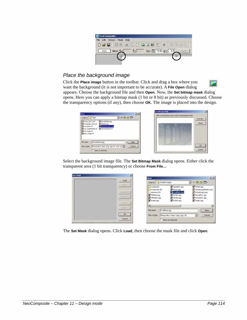
Place the background image Click the Place image button in the toolbar. Click and drag a box where you want the background (it is not important to be accurate). A File Open dialog appears. Choose the background file and then Open. Now, the Set bitmap mask dialog opens. Here you can apply a bitmap mask (1 bit or 8 bit) as previously discussed. Choose the transparency options (if any), then choose OK. The image is placed into the design.
Select the background image file. The Set Bitmap Mask dialog opens. Either click the transparent area (1 bit transparency) or choose From File…
The Set Mask dialog opens. Click Load, then choose the mask file and click Open.
NeoComposite – Chapter 11 – Design mode Page 114
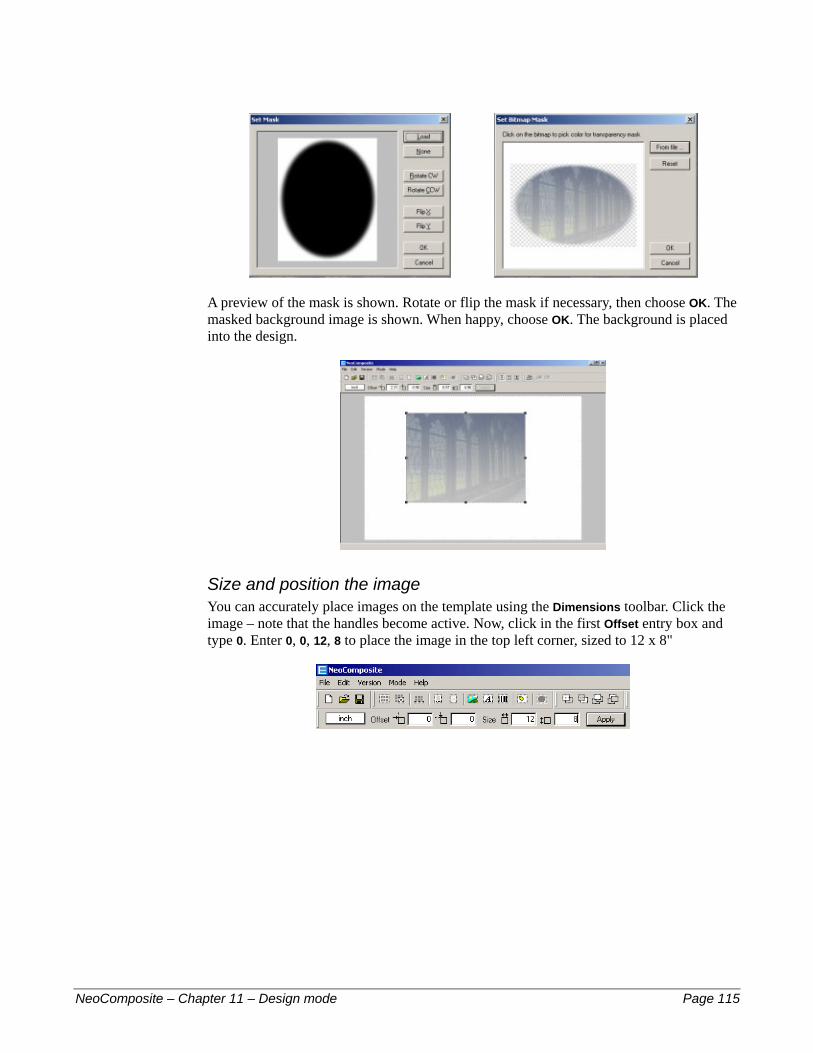
A preview of the mask is shown. Rotate or flip the mask if necessary, then choose OK. The masked background image is shown. When happy, choose OK. The background is placed into the design.
Size and position the image You can accurately place images on the template using the Dimensions toolbar. Click the image – note that the handles become active. Now, click in the first Offset entry box and type 0. Enter 0, 0, 12, 8 to place the image in the top left corner, sized to 12 x 8"
NeoComposite – Chapter 11 – Design mode Page 115
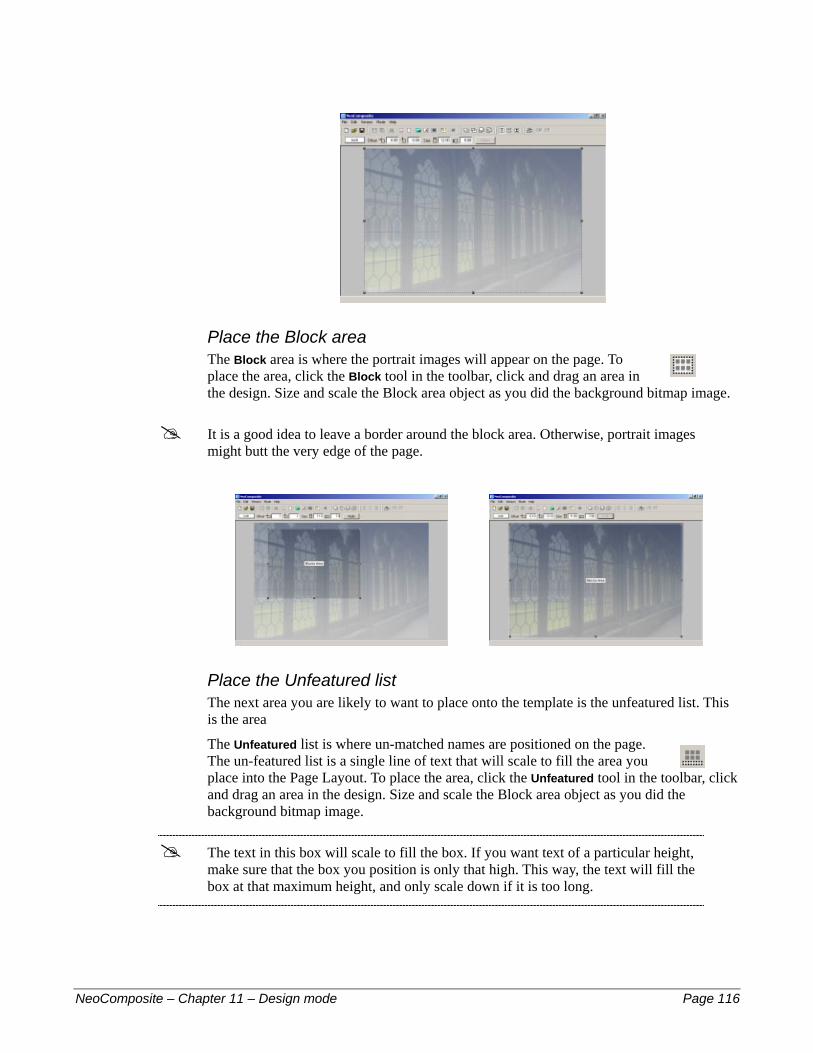
Place the Block area The Block area is where the portrait images will appear on the page. To place the area, click the Block tool in the toolbar, click and drag an area in the design. Size and scale the Block area object as you did the background bitmap image.
! It is a good idea to leave a border around the block area. Otherwise, portrait images might butt the very edge of the page.
Place the Unfeatured list The next area you are likely to want to place onto the template is the unfeatured list. This is the area
The Unfeatured list is where un-matched names are positioned on the page. The un-featured list is a single line of text that will scale to fill the area you place into the Page Layout. To place the area, click the Unfeatured tool in the toolbar, click and drag an area in the design. Size and scale the Block area object as you did the background bitmap image.
! The text in this box will scale to fill the box. If you want text of a particular height, make sure that the box you position is only that high. This way, the text will fill the box at that maximum height, and only scale down if it is too long.
NeoComposite – Chapter 11 – Design mode Page 116
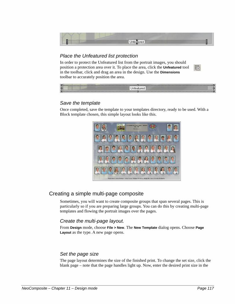
Place the Unfeatured list protection In order to protect the Unfeatured list from the portrait images, you should position a protection area over it. To place the area, click the Unfeatured tool in the toolbar, click and drag an area in the design. Use the Dimensions toolbar to accurately position the area.
Save the template Once completed, save the template to your templates directory, ready to be used. With a Block template chosen, this simple layout looks like this.
Creating a simple multi-page composite Sometimes, you will want to create composite groups that span several pages. This is particularly so if you are preparing large groups. You can do this by creating multi-page templates and flowing the portrait images over the pages.
Create the multi-page layout. From Design mode, choose File > New. The New Template dialog opens. Choose Page Layout as the type. A new page opens.
Set the page size The page layout determines the size of the finished print. To change the set size, click the blank page – note that the page handles light up. Now, enter the desired print size in the
NeoComposite – Chapter 11 – Design mode Page 117

Dimensions toolbar and click Apply. The page changes to the new size. In this example, choose a page of 24 x 8".
Set the cut position Setting a cut mark defines where the page will be split when printed. To set the cut mark, choose Edit > Cut Marks… the Cut Marks dialog opens. In this case, we want the page to be split at the 12" mark in the page.
Place the background images Place the first background image onto the page.
Place the second background image onto the page
NeoComposite – Chapter 11 – Design mode Page 118

Place the block areas Click and drag the first Block area onto the page
Then the second block on the second page
Set the board options The centre board can appear on one or all of the block areas you define. In this case, you might only want the board to appear on the first page of this series. To set this, choose the block area you want to have the board, and choose Edit > Object Attributes… the Composite Blocks Area dialog opens.
To enable boards for this area, check If a board is requested, include one in this area. Now, when a board is chosen, it will appear on this page.
NeoComposite – Chapter 11 – Design mode Page 119

Place the Unfeatured list The Unfeatured list is where un-matched names are positioned on the page. The un-featured list is a single line of text that will scale to fill the area you place into the Page Layout. To place the area, click the Unfeatured tool in the toolbar, click and drag an area in the design. Size and scale the Block area object as you did the background bitmap image.
Because this page has several pages,. You might want to place an unfeatured list on all pages. If more than one unfeatured list is placed over several pages, each page will show the same list of names.
! The text in this box will scale to fill the box. If you want text of a particular height, make sure that the box you position is only that high. This way, the text will fill the box at that maximum height, and only scale down if it is too long.
Place the Unfeatured list protection In order to protect the Unfeatured list from the portrait images, you should position a protection area over it. To place the area, click the Unfeatured tool in the toolbar, click and drag an area in the design. Use the Dimensions toolbar to accurately position the area.
Save the template Once completed, save the template to your templates directory, ready to be used. With a Block template chosen, this split page layout looks like this.
NeoComposite – Chapter 11 – Design mode Page 120

Creating ‘protected’ pages Your designers might create pages that have important graphic elements in the background. You can place protection areas over the design and so ensure that the important graphics are not obscured by portrait images.
Create the base page Create a new Page layout, and size it 12x8". Place the graphic background on the page, size and position it with the Dimensions toolbar.
Add the Blocks area Add, size and position the blocks area.
Add the first protection area It is important that the protection areas are placed on top of the block area. This indicates to NeoComposite that the portraits are not to flow over the protected area. If you place the protection area behind portrait area, the portraits will ignore it and flow over the area.
NeoComposite – Chapter 11 – Design mode Page 121
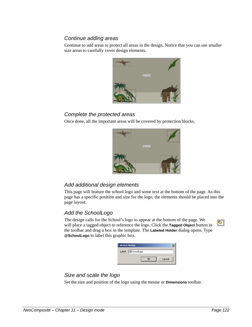
Continue adding areas Continue to add areas to protect all areas in the design. Notice that you can use smaller size areas to carefully cover design elements.
Complete the protected areas Once done, all the important areas will be covered by protection blocks.
Add additional design elements This page will feature the school logo and some text at the bottom of the page. As this page has a specific position and size for the logo, the elements should be placed into the page layout.
Add the SchoolLogo The design calls for the School’s logo to appear at the bottom of the page. We will place a tagged object to reference the logo. Click the Tagged Object button in the toolbar and drag a box in the template. The Labeled Holder dialog opens. Type @SchoolLogo to label this graphic box.
Size and scale the logo Set the size and position of the logo using the mouse or Dimensions toolbar.
NeoComposite – Chapter 11 – Design mode Page 122

Add the text box The following text is to appear in the design:
The School name #
#
#
#
The Composite name The Year of photography The Principal’s name
The codes that should be used to achieve this is a mix of internal and Details codes (see the previous chapter, Details). The codes to use are:
Desired text Type @Code
School Name Details field @SchoolName
Composite Name Internal @Composite
Year of Photography Details field @Year
Principal’s name Label / Details field @Principal
Click the Text button in the toolbar, then drag a text box in the design. The Text dialog opens. Enter the following text:
@SchoolName - @Name @Composite
Principal: @<Principal>:name Select the entered text and select a font.
NeoComposite – Chapter 11 – Design mode Page 123
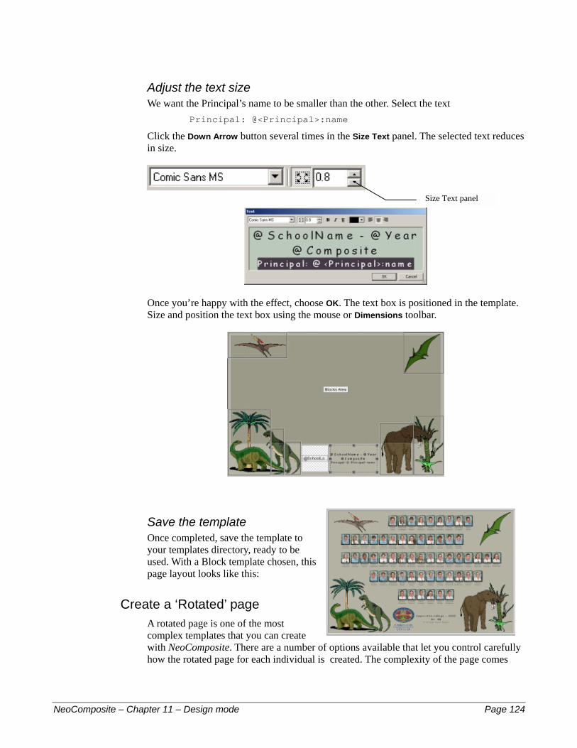
Adjust the text size We want the Principal’s name to be smaller than the other. Select the text
Principal: @<Principal>:name
Click the Down Arrow button several times in the Size Text panel. The selected text reduces in size.
Size Text panel
Once you’re happy with the effect, choose OK. The text box is positioned in the template. Size and position the text box using the mouse or Dimensions toolbar.
Save the template Once completed, save the template to your templates directory, ready to be used. With a Block template chosen, this page layout looks like this:
Create a ‘Rotated’ page A rotated page is one of the most complex templates that you can create with NeoComposite. There are a number of options available that let you control carefully how the rotated page for each individual is created. The complexity of the page comes
NeoComposite – Chapter 11 – Design mode Page 124

from the fact that the group of individuals included in the page may contain some who don’t have a portrait available to include. On a simple composite page, their name would be simply added to an absent line, but when as page contains a larger rotated image, this approach won’t work. If they don’t have a portrait, what should appear in the larger portrait image?
NeoComposite addresses this issue by allowing you to design a specific ‘Static’ and ‘Rotated’ version of the same page. The static version removes the larger portrait image, creating a conventional composite for the missing individual. The process is automatic, and no operator action is required to complete the production for the group.
This individual doesn’t have a portrait available
A static version is created for the missing individual
Create a simple rotated template A rotated template can contain a single rotated page, or you can design a separate rotated version if desired.
Create the page Create the base page as previously described.
Create the page #
#
#
#
#
Place the background Place the Blocks area Place any other graphic areas – including tagged objects Place the un-featured list and protection area if required
NeoComposite – Chapter 11 – Design mode Page 125

Place any text boxes – including ‘@’ codes #
! The ‘@’ codes used on this page are the same as those in the previous example.
Place the ‘Rotated’ portrait
Click the Rotated Portrait button in the toolbar. Click and drag the box in the template.
Size and position the Rotation Position and size the rotated area in the template. Any Subject blocks placed into the rotated area will be scaled to fit the area, but try to make the size of the area match the Subject block being used.
NeoComposite – Chapter 11 – Design mode Page 126

Save the template Once completed, save the template to your templates directory, ready to be used. With a Block template chosen, the rotated and static versions of the page layout look like this:
Create a page with separate Rotated and Static versions You might want to create a rotated page that has different elements for the Rotated and Static pages. You can design a template that contains two separate versions of the same page, one rotated and one static.
Create the different versions Open the template that you created in the previous example. Click the Use different versions button in the toolbar. Note that the Rotated and Static version buttons become active.
Click the Use Separate Versions button To activate the separate versions of the template
NeoComposite – Chapter 11 – Design mode Page 127

Switch between versions You can switch between the two versions by clicking the relevant button. After you make changes to the version, you will notice the changes.
Edit the Static version In this static version, we want to remove the rotated portrait block and widen the Unfeatured list. Make sure you have the Static version selected by clicking the Static Version button in the toolbar.
Click the Static Version button
Remove the rotated portrait Click the rotated portrait on the page and press the Delete key. The rotated portrait is deleted.
Widen the Unfeatured list Press the Tab key, or hold the CTRL key down and click the Unfeatured list box until it is selected. Adjust the width so it is filling the bottom of the page using the mouse or Dimensions toolbar. Switch between the two versions by clicking the Rotated Version and then the Static Version buttons in the toolbar.
Rotated Version
Static Version
Save the template Once completed, save the template to your templates directory, ready to be used. With a Block template chosen, the rotated and static versions of the page layout looks like this:
NeoComposite – Chapter 11 – Design mode Page 128

Subject blocks Subject blocks define how the portraits will appear on the page. They are constructed in the same way as the Page Layout templates. They also contain the font formatting for the Unfeatured list, ensuring that the font styles match.
Subject block components Subject blocks can contain a number of objects, including graphics, text, masks etc. You should use your favourite bitmap or vector editor to create the various graphic elements for the template. You then place these objects, add the masks and text to complete the design.
Creating a Subject Block template Switch to Design mode by choosing Mode > Design or pressing the F8 key. Choose File > New. The New Template dialog opens – choose the Subject Block option. A new subject Block opens.
NeoComposite – Chapter 11 – Design mode Page 129
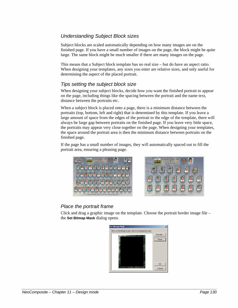
Understanding Subject Block sizes Subject blocks are scaled automatically depending on how many images are on the finished page. If you have a small number of images on the page, the block might be quite large. The same block might be much smaller if there are many images on the page.
This means that a Subject block template has no real size – but do have an aspect ratio. When designing your templates, any sizes you enter are relative sizes, and only useful for determining the aspect of the placed portrait.
Tips setting the subject block size When designing your subject blocks, decide how you want the finished portrait to appear on the page, including things like the spacing between the portrait and the name text, distance between the portraits etc.
When a subject block is placed onto a page, there is a minimum distance between the portraits (top, bottom, left and right) that is determined by this template. If you leave a large amount of space from the edges of the portrait to the edge of the template, there will always be large gap between portraits on the finished page. If you leave very little space, the portraits may appear very close together on the page. When designing your templates, the space around the portrait area is then the minimum distance between portraits on the finished page.
If the page has a small number of images, they will automatically spaced out to fill the portrait area, ensuring a pleasing page.
Place the portrait frame Click and drag a graphic image on the template. Choose the portrait border image file – the Set Bitmap Mask dialog opens.
NeoComposite – Chapter 11 – Design mode Page 130
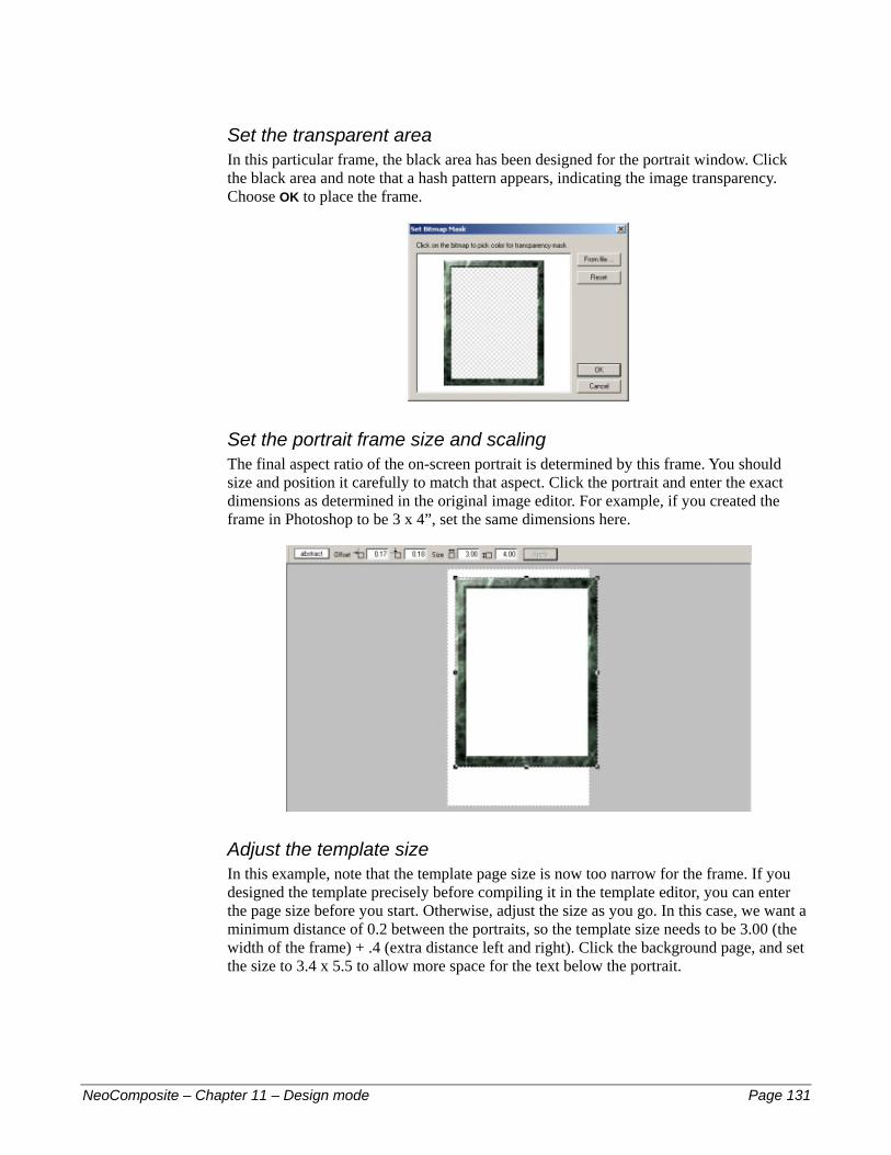
Set the transparent area In this particular frame, the black area has been designed for the portrait window. Click the black area and note that a hash pattern appears, indicating the image transparency. Choose OK to place the frame.
Set the portrait frame size and scaling The final aspect ratio of the on-screen portrait is determined by this frame. You should size and position it carefully to match that aspect. Click the portrait and enter the exact dimensions as determined in the original image editor. For example, if you created the frame in Photoshop to be 3 x 4”, set the same dimensions here.
Adjust the template size In this example, note that the template page size is now too narrow for the frame. If you designed the template precisely before compiling it in the template editor, you can enter the page size before you start. Otherwise, adjust the size as you go. In this case, we want a minimum distance of 0.2 between the portraits, so the template size needs to be 3.00 (the width of the frame) + .4 (extra distance left and right). Click the background page, and set the size to 3.4 x 5.5 to allow more space for the text below the portrait.
NeoComposite – Chapter 11 – Design mode Page 131

Position the frame Click the frame, and accurately position it using the Dimensions toolbar. We want to have slightly more space above the portrait than left or right. Enter the following values:
Horizontal offset – 0.20 #
#
#
#
Vertical Offset – 0.35 Width – 3.00 Height – 4.00
Place the portrait hole The portrait image will appear in the transparent area defined previously. We need to place an image hole and position it behind the frame to achieve the
NeoComposite – Chapter 11 – Design mode Page 132

effect. Click and drag an image hole onto the template. Position it in place over the transparent area. Note that the area is in front of the frame.
Change the layer position In order for the frame and portrait images to merge, the image hole needs to be placed behind the frame. Select the hole and click the Send to Back button in the Layer toolbar. Note that when you click the Send to Back button that the image hold and frame merge.
Click the Send to Back button
Add the names and formatting Each portrait should have a name under it, you control the way the name text is formatted by placing a text box in the template. Click and drag a text box onto the template using the Text tool. The Text dialog opens. Choose the font and color you want, then ensure Centred is set as the alignment. Enter the text: @FirstName @LastName
NeoComposite – Chapter 11 – Design mode Page 133
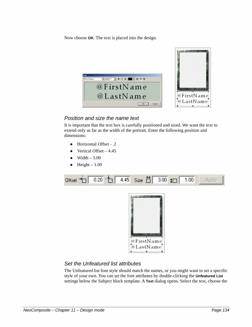
Now choose OK. The text is placed into the design.
Position and size the name text It is important that the text box is carefully positioned and sized. We want the text to extend only as far as the width of the portrait. Enter the following position and dimensions:
Horizontal Offset - .2 #
#
#
#
Vertical Offset – 4.45 Width – 3.00 Height – 1.00
Set the Unfeatured list attributes The Unfeatured list font style should match the names, or you might want to set a specific style of your own. You can set the font attributes by double-clicking the Unfeatured List settings below the Subject block template. A Text dialog opens. Select the text, choose the
NeoComposite – Chapter 11 – Design mode Page 134

font and color you want. You can edit the name of the Unfeatured list – perhaps to read ‘Absent’.
Save the template Once completed, save the template to your templates directory, ready to be used. The Subject block looks like this on the page:
NeoComposite – Chapter 11 – Design mode Page 135
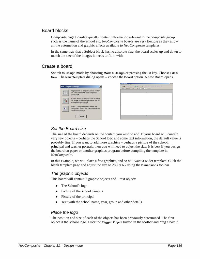
Board blocks Composite page Boards typically contain information relevant to the composite group such as the name of the school etc. NeoComposite boards are very flexible as they allow all the automation and graphic effects available to NeoComposite templates.
In the same way that a Subject block has no absolute size, the board scales up and down to match the size of the images it needs to fit in with.
Create a board Switch to Design mode by choosing Mode > Design or pressing the F8 key. Choose File > New. The New Template dialog opens – choose the Board option. A new Board opens.
Set the Board size The size of the board depends on the content you wish to add. If your board will contain very few objects – perhaps the School logo and some text information, the default value is probably fine. If you want to add more graphics – perhaps a picture of the school, principal and teacher portrait, then you will need to adjust the size. It is best if you design the board on paper or another graphics program before compiling the template in NeoComposite.
In this example, we will place a few graphics, and so will want a wider template. Click the blank template page and adjust the size to 28.2 x 6.7 using the Dimensions toolbar.
The graphic objects This board will contain 3 graphic objects and 1 text object:
The School’s logo #
#
#
#
Picture of the school campus Picture of the principal Text with the school name, year, group and other details
Place the logo The position and size of each of the objects has been previously determined. The first object is the school logo. Click the Tagged Object button in the toolbar and drag a box in
NeoComposite – Chapter 11 – Design mode Page 136

the template. The Labelled Holder dialog opens. Type @SchoolLogo to label this graphic box.
Size and position the logo using the Dimensions toolbar to .1, .7, 5.0, 5.0:
Add the text box The following text is to appear in the design:
The School name #
#
#
#
The Composite name The Year of photography The Principal’s name
The codes that should be used to achieve this is a mix of internal and Details codes (see the previous chapter, Details). The codes to use are:
Desired text Type @Code
School Name Details field @SchoolName
Composite Name Internal @Composite
Year of Photography Details field @Year
Principal’s name Label / Details field @Principal
Click the Text button in the toolbar, then drag a text box in the design. The Text dialog opens. Enter the following text:
@SchoolName - @Name
NeoComposite – Chapter 11 – Design mode Page 137

@Composite Principal: @<Principal>:name
Select the entered text and select a font.
Adjust the text size We want the Principal’s name to be smaller than the other. Select the text
Principal: @<Principal>:name
Click the Down Arrow button several times in the Size Text panel. The selected text reduces in size.
Size Text panel
Once you’re happy with the effect, choose OK. The text box is positioned in the template. Size and position the text box using the Dimensions toolbar to 6.40, 0.70, 11.00, 5.00:
Place the School picture The position and size of each of the objects has been previously determined. The first object is the school logo. Click the Tagged Object button in the toolbar and drag a box in
NeoComposite – Chapter 11 – Design mode Page 138

the template. The Labelled Holder dialog opens. Type @SchoolPic1 to label this graphic box.
Place the Principal’s picture The position and size of each of the objects has been previously determined. The first object is the school logo. Click the Tagged Object button in the toolbar and drag a box in the template. The Labelled Holder dialog opens. Type @Principal to label this graphic box.
! If you want the teacher’s (or another) picture instead of the principal’s, add the label name you will use for this graphic – (i.e. @Teacher) and label the individual in Details or Form Pages.
Save the template Once completed, save the template to your templates directory, ready to be used. With a Block template chosen, this page layout looks like this:
NeoComposite – Chapter 11 – Design mode Page 139
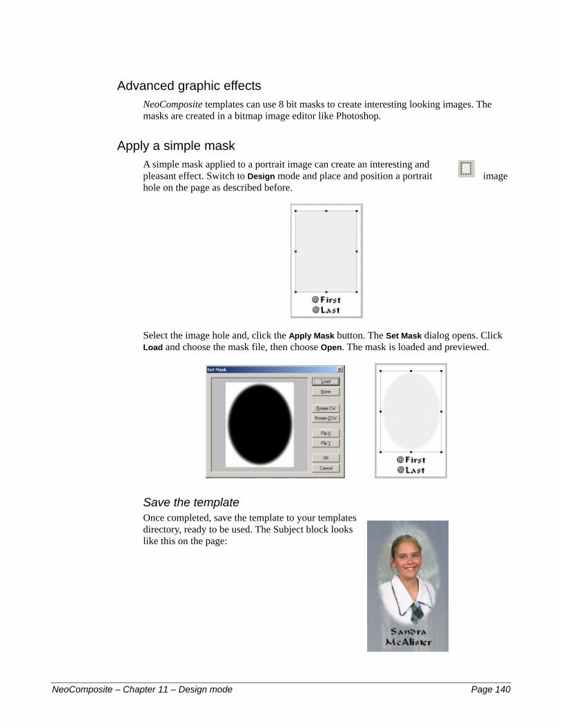
Advanced graphic effects NeoComposite templates can use 8 bit masks to create interesting looking images. The masks are created in a bitmap image editor like Photoshop.
Apply a simple mask A simple mask applied to a portrait image can create an interesting and pleasant effect. Switch to Design mode and place and position a portrait image hole on the page as described before.
Select the image hole and, click the Apply Mask button. The Set Mask dialog opens. Click Load and choose the mask file, then choose Open. The mask is loaded and previewed.
Save the template Once completed, save the template to your templates directory, ready to be used. The Subject block looks like this on the page:
NeoComposite – Chapter 11 – Design mode Page 140
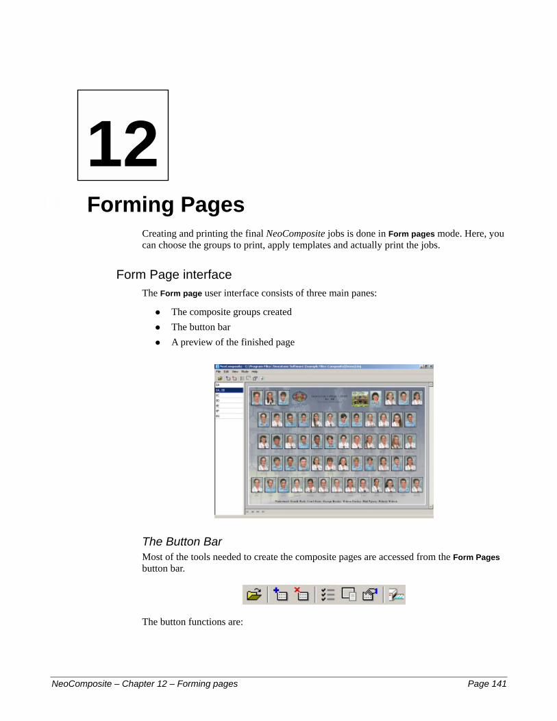
12 –
NeoCom
12
Forming PagesCreating and printing the final NeoComposite jobs is done in Form pages mode. Here, you can choose the groups to print, apply templates and actually print the jobs.
Form Page interface The Form page user interface consists of three main panes:
The composite groups created #
#
#
The button bar A preview of the finished page
The Button Bar Most of the tools needed to create the composite pages are accessed from the Form Pages button bar.
The button functions are:
posite – Chapter 12 – Forming pages Page 141

Button Description
Open File Opens a Composite Job File
Add a page composite Creates a new composite page
Delete a page composite Deletes an existing composite page
Subjects to include Choose the subjects to include on a page
Choose the Page templates Select the templates to use
Settings options Specify the order images are displayed on the page and control how unmatched images should be handled
Print Opens the print dialog
Create a new Composite page Create a new Composite page by choosing Edit > New… or clicking Add a page composite button in the toolbar. The Subjects to include dialog opens.
Choose the subjects Expand the list of available groups by clicking the ‘+’, and then the group to include. Note that the list of names appears, and the name of the composite group added to the Description.
! The Description is the text that will appear in the final page where a template uses the ‘@composite’ code. You can edit this text if desired.
NeoComposite – Chapter 12 – Forming pages Page 142
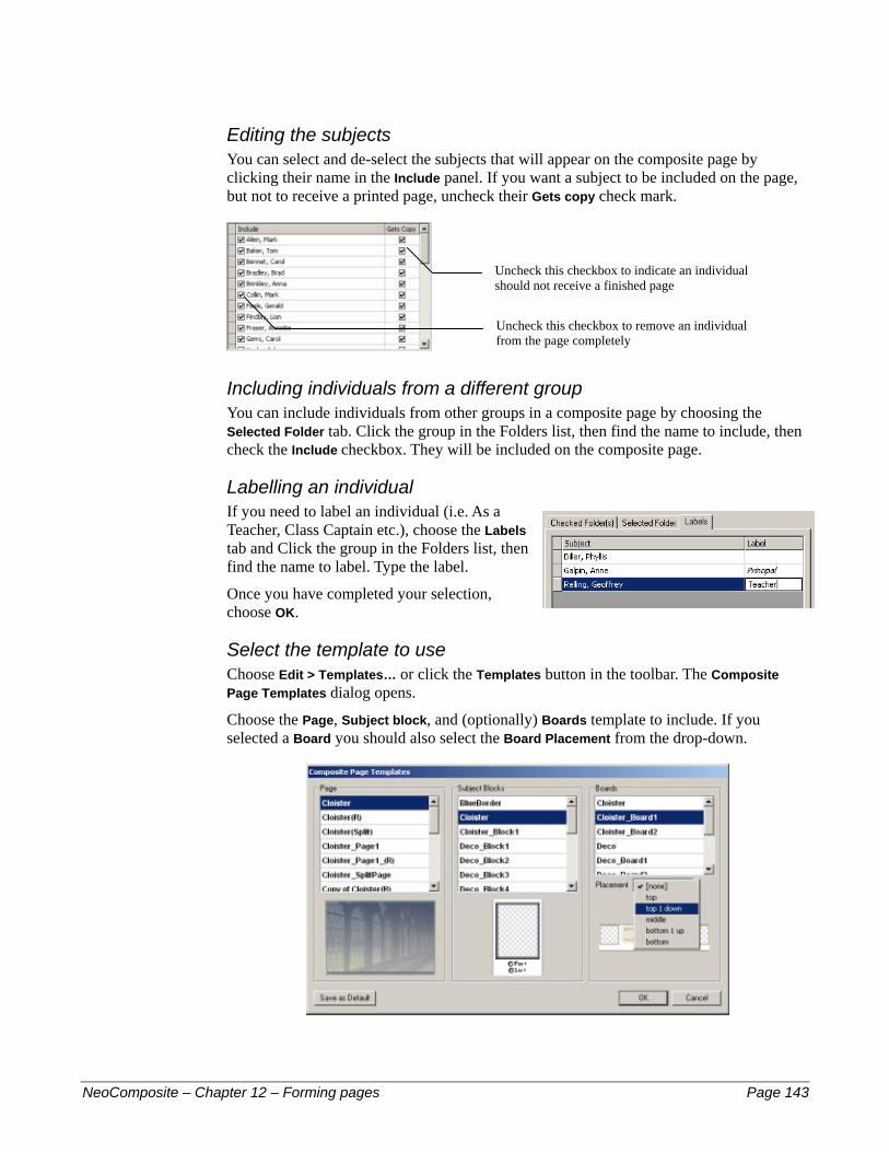
Editing the subjects You can select and de-select the subjects that will appear on the composite page by clicking their name in the Include panel. If you want a subject to be included on the page, but not to receive a printed page, uncheck their Gets copy check mark.
Uncheck this checkbox to remove an individual from the page completely
Uncheck this checkbox to indicate an individual should not receive a finished page
Including individuals from a different group You can include individuals from other groups in a composite page by choosing the Selected Folder tab. Click the group in the Folders list, then find the name to include, then check the Include checkbox. They will be included on the composite page.
Labelling an individual If you need to label an individual (i.e. As a Teacher, Class Captain etc.), choose the Labels tab and Click the group in the Folders list, then find the name to label. Type the label.
Once you have completed your selection, choose OK.
Select the template to use Choose Edit > Templates… or click the Templates button in the toolbar. The Composite Page Templates dialog opens.
Choose the Page, Subject block, and (optionally) Boards template to include. If you selected a Board you should also select the Board Placement from the drop-down.
NeoComposite – Chapter 12 – Forming pages Page 143
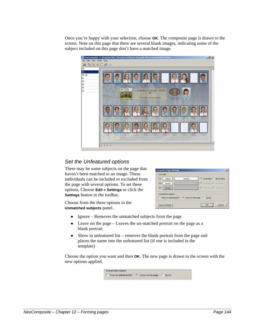
Once you’re happy with your selection, choose OK. The composite page is drawn to the screen. Note on this page that there are several blank images, indicating some of the subject included on this page don’t have a matched image.
Set the Unfeatured options There may be some subjects on the page that haven’t been matched to an image. These individuals can be included or excluded from the page with several options. To set these options, Choose Edit > Settings or click the Settings button in the toolbar.
Choose from the three options in the Unmatched subjects panel.
Ignore – Removes the unmatched subjects from the page #
#
#
Leave on the page – Leaves the un-matched portrait on the page as a blank portrait Show in unfeatured list – removes the blank portrait from the page and places the name into the unfeatured list (if one is included in the template)
Choose the option you want and then OK. The new page is drawn to the screen with the new options applied.
NeoComposite – Chapter 12 – Forming pages Page 144

Setting the sort options You can set three levels of sorting for the composite group. For example, you could create a ‘Whole School’ composite page that is sorted by group, then by name. The result is that each group is kept together and sorted alphabetically. To set the sort options, choose Edit > Settings… or click the Settings button in the toolbar.
Set the first order sort Click the 1st drop down and choose the field to sort by. Choose Subject to sort by a subject field or Folder to sort by a folder field.
Set the first order sort criteria Click the [name] drop-down to reveal the available sorting criteria. This is dependent on the folder fields you have defined in Details. Select your choice.
NeoComposite – Chapter 12 – Forming pages Page 145

Set the second order sort and criteria Select the sort field and criteria by selecting from those available. Again, the choices will depend on the fields you have defined in Details.
Once you have made your selection, choose OK. The page is re-drawn with the sorting criteria applied.
Rotated pages If you have selected a rotated page, the first page of the group is displayed, along with navigation controls at the bottom of the preview window. You can scroll through the rotated pages using these buttons.
First page
Forward one page
Last page
Back one page
NeoComposite – Chapter 12 – Forming pages Page 146
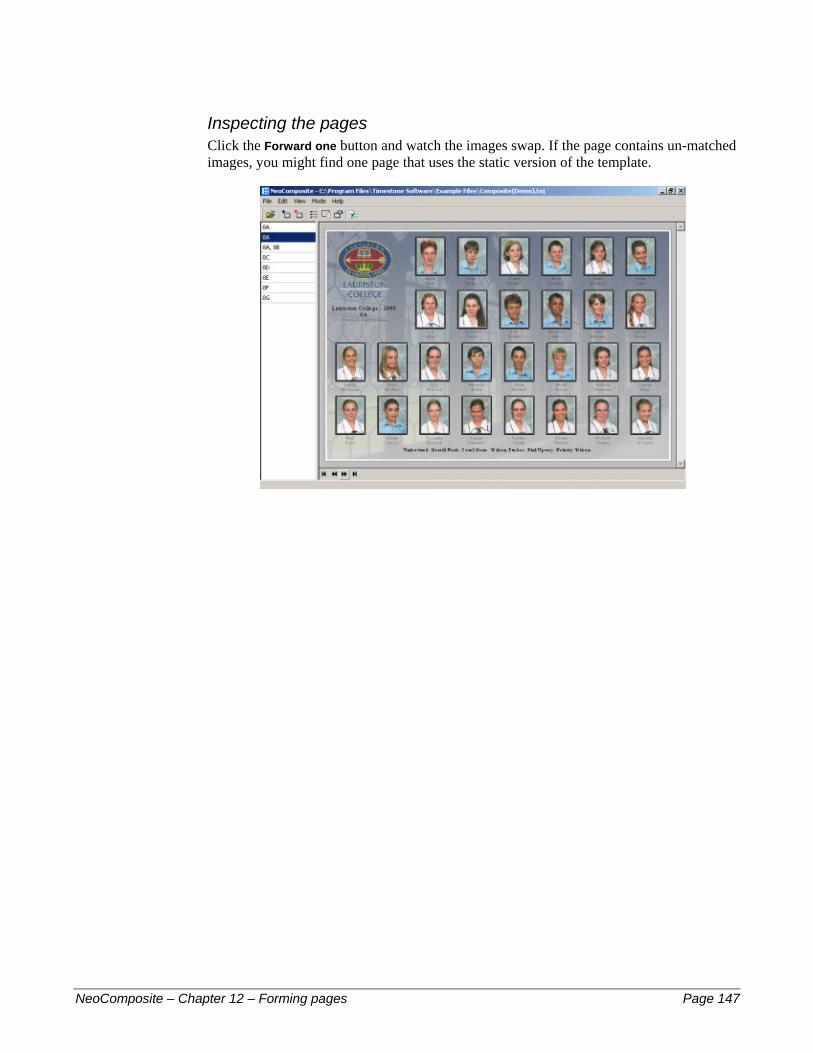
Inspecting the pages Click the Forward one button and watch the images swap. If the page contains un-matched images, you might find one page that uses the static version of the template.
NeoComposite – Chapter 12 – Forming pages Page 147

13 –
NeoCom
13
PrintingNeoComposite offers a wide variety of printing options. You can choose to print to a standard Windows NT printer driver, output bitmap files or ‘print’ to a Timestone Print Job file. Timestone Software has produced a number of Windows NT printer drivers for some of the more popular digital photographic printers, and NeoComposite can take advantage of the special features built into these drivers
If a printer driver isn’t available for your printer, you can output bitmap image files to submit to the printer using your normal printing software.
Printing to a Timestone Print Job file allows NeoComposite to participate in our Distributed Print Architecture. This is a system than minimises the time your operators wait while a job is printed, as well as ensuring there are enough prepared jobs ready to be printed by your high-speed digital printer.
Select the Groups Choose File > Print or click the Print button in the toolbar. The Print dialog opens. The dialog is divided into several sections.
The Printer to use
Copies to print
Groups and individuals who will receive prints
Bitmap output options
posite – Chapter 13 – Printing Page 148
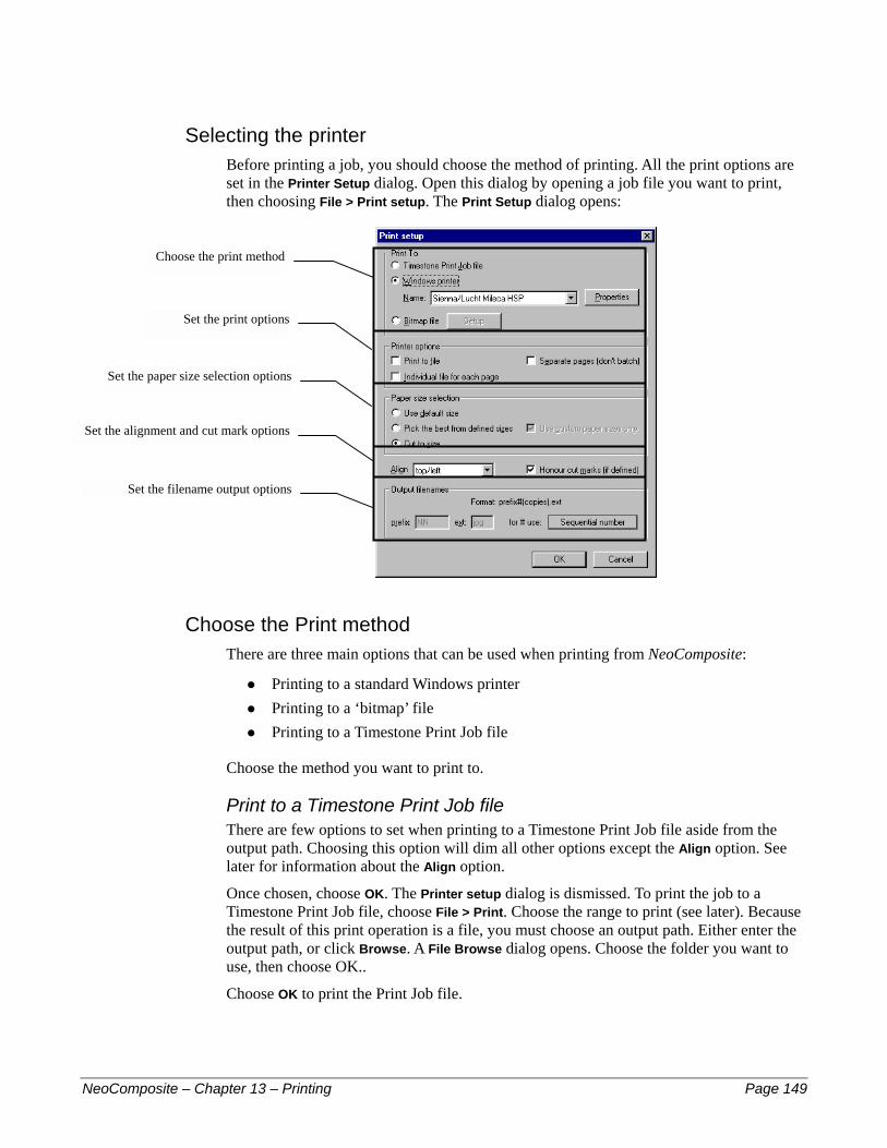
Selecting the printer Before printing a job, you should choose the method of printing. All the print options are set in the Printer Setup dialog. Open this dialog by opening a job file you want to print, then choosing File > Print setup. The Print Setup dialog opens:
Choose the print method
Set the print options
Set the paper size selection options
Set the alignment and cut mark options
Set the filename output options
Choose the Print method There are three main options that can be used when printing from NeoComposite:
Printing to a standard Windows printer #
#
#
Printing to a ‘bitmap’ file Printing to a Timestone Print Job file
Choose the method you want to print to.
Print to a Timestone Print Job file There are few options to set when printing to a Timestone Print Job file aside from the output path. Choosing this option will dim all other options except the Align option. See later for information about the Align option.
Once chosen, choose OK. The Printer setup dialog is dismissed. To print the job to a Timestone Print Job file, choose File > Print. Choose the range to print (see later). Because the result of this print operation is a file, you must choose an output path. Either enter the output path, or click Browse. A File Browse dialog opens. Choose the folder you want to use, then choose OK..
Choose OK to print the Print Job file.
NeoComposite – Chapter 13 – Printing Page 149

Print to a Standard Windows NT printer driver You can use a standard Windows NT printer driver to print from NeoComposite. There are a number of special features built into NeoComposite that automate paper size selection and a number of other options.
To choose a Windows NT printer, choose Windows printer as the Print to option, then choose the printer you wish to use by clicking the Printer drop-down and selecting it from the list. Set any printer specific options by choosing Properties. For information on the options to set, consult your printer’s driver documentation.
Print to a bitmap file NeoComposite can output bitmap files directly by choosing Bitmap file as the Print to option. Once selected, the Setup button becomes active. Click it to set the various options.
! When printing to bitmap files, any hard cut marks set in a template will be honoured, and a number of files will be created for the split pack.
Set the output resolution and format Choose the output resolution by clicking the DPI drop-down. You can choose from a variety of output file types by clicking the Format drop-down and selecting the desired format.
Set color correction Choose an output LUT from those available by clicking the Apply LUT drop-down and choosing from the list. For more information on creating LUT’s see chapter 12 for further information about LUT’s.
NeoComposite – Chapter 13 – Printing Page 150

Set the sharpness You can apply a sharpness correction by checking the Sharpen checkbox. Choose the Kernel size and strength.
! Generally, you should leave the Kernel at 3. You will have to test the sharpness strength for your system.
Set the filename option There are a number of file naming options when printing to bitmap files. Once you choose Bitmap file as the Print to, the Output filenames panel becomes active.
Files printed are named:
[Prefix][Number][Copies].[ext]
[Prefix] – each printed file will begin with the text entered #
#
#
#
[Number] – the main filename given to each printed file [Copies] – the number of copies requested in the print dialog [ext] – the filename extension
You can specify the main name used for the filename by clicking for # use and selecting from the choices available. The choices are:
Option Description
Image No. NeoComposite uses the image number – either the sequential or indexed number to name the file. If multiple packages are created, a sequential number is appended for each pack with the same image number.
Original image tag
NeoComposite uses the special image tag, if used when importing the images, to name the files. If multiple packages are created, a sequential number is appended for each pack with the same image number.
Sequential no.
NeoComposite creates its own sequential number to name the files. Different packs from the same image are gathered together sequentially, but will be named different one to the other.
NeoComposite – Chapter 13 – Printing Page 151

Once all the options have been set, choose OK.
Set the output path To print the job to Bitmap files, choose File > Print. Choose the range to print (see later). Because the result of this print operation is a file, you must choose an output path. Either enter the output path, or click Browse. A File Browse dialog opens. Choose the folder you want to use, then choose OK..
Choose OK to print the bitmap files.
! If Sequential number has been selected as the for # use option, you will be able to enter the first sequential number to use. Enter the starting number in the Next sequential number entry box.
Printing to a standard Windows printer driver There are a number of options that can help automate your printing when using NeoComposite. The main options are:
Printer Properties – configure printer specific options #
#
#
#
Printer output options – choose whether to output to a file, or to the printer Paper size selection – paper size automation functions Alignment and cut marks – how the printed image is aligned and if cut marks are on or off
Set the printer properties After selecting the printer to use, you can configure the various printer properties by choosing Properties from the Print setup dialog. The options displayed here are dependent on your printer’s driver software, and you should consult the driver software documentation for further information when setting these options.
NeoComposite – Chapter 13 – Printing Page 152
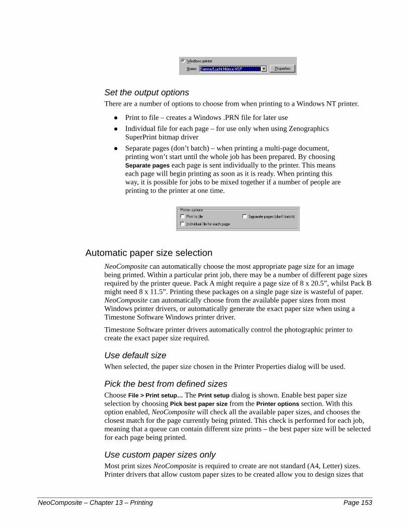
Set the output options There are a number of options to choose from when printing to a Windows NT printer.
Print to file – creates a Windows .PRN file for later use #
#
#
Individual file for each page – for use only when using Zenographics SuperPrint bitmap driver Separate pages (don’t batch) – when printing a multi-page document, printing won’t start until the whole job has been prepared. By choosing Separate pages each page is sent individually to the printer. This means each page will begin printing as soon as it is ready. When printing this way, it is possible for jobs to be mixed together if a number of people are printing to the printer at one time.
Automatic paper size selection NeoComposite can automatically choose the most appropriate page size for an image being printed. Within a particular print job, there may be a number of different page sizes required by the printer queue. Pack A might require a page size of 8 x 20.5”, whilst Pack B might need 8 x 11.5”. Printing these packages on a single page size is wasteful of paper. NeoComposite can automatically choose from the available paper sizes from most Windows printer drivers, or automatically generate the exact paper size when using a Timestone Software Windows printer driver.
Timestone Software printer drivers automatically control the photographic printer to create the exact paper size required.
Use default size When selected, the paper size chosen in the Printer Properties dialog will be used.
Pick the best from defined sizes Choose File > Print setup… The Print setup dialog is shown. Enable best paper size selection by choosing Pick best paper size from the Printer options section. With this option enabled, NeoComposite will check all the available paper sizes, and chooses the closest match for the page currently being printed. This check is performed for each job, meaning that a queue can contain different size prints – the best paper size will be selected for each page being printed.
Use custom paper sizes only Most print sizes NeoComposite is required to create are not standard (A4, Letter) sizes. Printer drivers that allow custom paper sizes to be created allow you to design sizes that
NeoComposite – Chapter 13 – Printing Page 153
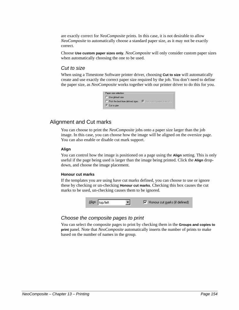
are exactly correct for NeoComposite prints. In this case, it is not desirable to allow NeoComposite to automatically choose a standard paper size, as it may not be exactly correct.
Choose Use custom paper sizes only. NeoComposite will only consider custom paper sizes when automatically choosing the one to be used.
Cut to size When using a Timestone Software printer driver, choosing Cut to size will automatically create and use exactly the correct paper size required by the job. You don’t need to define the paper size, as NeoComposite works together with our printer driver to do this for you.
Alignment and Cut marks You can choose to print the NeoComposite jobs onto a paper size larger than the job image. In this case, you can choose how the image will be aligned on the oversize page. You can also enable or disable cut mark support.
Align You can control how the image is positioned on a page using the Align setting. This is only useful if the page being used is larger than the image being printed. Click the Align drop-down, and choose the image placement.
Honour cut marks If the templates you are using have cut marks defined, you can choose to use or ignore these by checking or un-checking Honour cut marks. Checking this box causes the cut marks to be used, un-checking causes them to be ignored.
Choose the composite pages to print You can select the composite pages to print by checking them in the Groups and copies to print panel. Note that NeoComposite automatically inserts the number of prints to make based on the number of names in the group.
NeoComposite – Chapter 13 – Printing Page 154
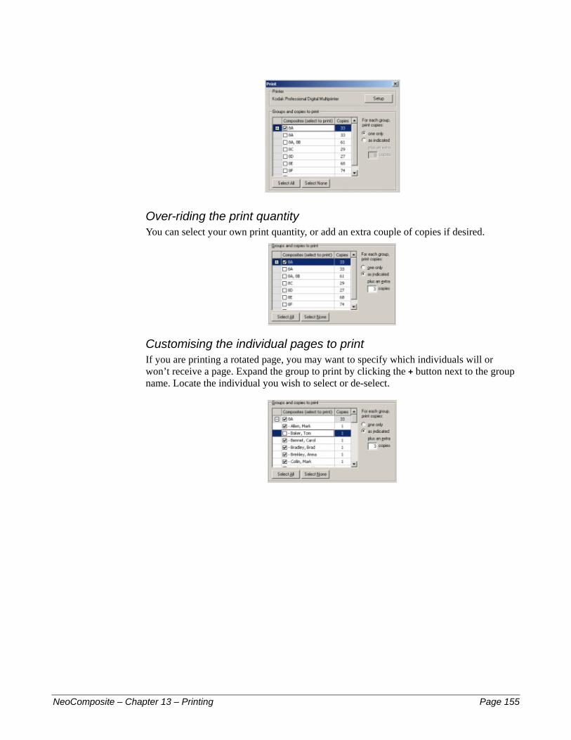
Over-riding the print quantity You can select your own print quantity, or add an extra couple of copies if desired.
Customising the individual pages to print If you are printing a rotated page, you may want to specify which individuals will or won’t receive a page. Expand the group to print by clicking the + button next to the group name. Locate the individual you wish to select or de-select.
NeoComposite – Chapter 13 – Printing Page 155

14 –
NeoCo
1414
Calibration & Color Management ! Note: Timestone Software’s Neo family of products use the ICC color managementsystem that Microsoft has built into Windows 2000. If you are using Windows 2000, you should use the ICM-2 color management system in preference to taking the steps described in previous versions of this manual. ICC color management involves creating ‘color profiles’ for every display or output device on your system, and is considerably more sophisticated than the previous method. However, the ‘calibration’ method of color management, and the creation of LUTs (Look-Up Tables) to achieve consistent color correction is still valid if you have not yet upgraded to Windows 2000, and both methods are now described in our separate Color Management Guide, which should be available on the same CD-ROM that this manual was on – or you can download it from our website at: http://www.timestone.com.au
mposite – Chapter 14 – Calibration & Color Management Page 156
Index .TNJ files ...............................................................32
compacting ........................................................63 Adding
images to a file ..................................................63 Adjusting image color, density & contrast ............68 Aspect Ratios.........................................................28
changing order of ..............................................29 creating new ......................................................29 default................................................................28 defining .............................................................28 displaying indicators .........................................29 importing...........................................................29
Block areas ............................................................81 Camera cards .........................................................72 Color management...............................................156 Compacting the job file .........................................63 Correcting images
while importing .................................................61 Cropping images....................................................67 Deleting
images ...............................................................63 Design file ..........................................See Templates Disk space..............................................................13 Dongle ................................................. See Hardlock Editing
images ...............................................................27 Editing images
using external application .................................64 Enable monitor LUT checkbox .............................33 Exporting images................... See Images, exporting Fields
adding................................................................30 default................................................................30 folder fields .......................................................31 labeled holders ..................................................51 special attributes................................................30 subject ...............................................................30
Filename format in an import image mask ...................................58 when exporting images .....................................69
Getting help ...........................................................12 Hard disk space......................................................13 Hardlock ................................................................17 Hardware requirements .........................................12 Help .......................................................................12 Hot source
importing from a................................................61 ICC color management ........................................156 Images
adding to a file...................................................63 adjusting
color, brightness & contrast ................... 68 appending on import..........................................60 aspect ratios .......................................................28 changing the number of images displayed ........65 color, adjusting ..................................................68 contrast, adjusting..............................................68 correcting while importing ..........................55, 62 cropping.............................................................67 editing................................................................27 editing while importing .....................................62 editing with an external application ..................64 exporting ...........................................................69 import options ...................................................59 import order.......................................................59 importing .....................................................55, 59 importing a range of ....................................57, 58 importing from hot source.................................61 importing from Kinetic bitmap devices.............62 importing from the Windows clipboard ............62 importing in reverse order .................................60 importing labeled objects ..................................51 importing using a mask .....................................57 inserting on import ......................................60, 63 jogging...............................................................67 labeled holders...........................................50, 109 location of....................................................32, 35 logos, etc. ..........................................................51 missing ..............................................................61 pausing during import .......................................60 referenced ..........................................................60 replacing on import ...........................................60 root directory .....................................................32 rotating while importing..............................56, 62 selecting.............................................................66 selecting to import .............................................59 setting import options........................................55 sharpening while importing.........................57, 62 storage of ...........................................................32 white space around ............................................67 zooming.............................................................67
Import options..................................................35, 59
NeoComposite – Index Page 157

Importing images...................See Images, importing Indexed file............................................................59 Job files
closing ...............................................................63 compacting ........................................................63 saving ................................................................63 size of ................................................................63
Labeled holders .............................................51, 110 License Server
backing up .........................................................19 codes..................................................................18 configuring and testing......................................17 installing............................................................16 'Last Error' info .................................................19 setup ..................................................................18 understanding ....................................................16 where to install ..................................................16
Licenses adding new ........................................................18 enabling.............................................................18 insufficient ........................................................16 multiple user......................................................16 single user .........................................................16
Logos .........................................See Labeled holders LookUp Tables ..........................................See LUTs LUTs......................................................................61 Masks
filename, when importing images .....................58 Match mode...........................................................71 Matching
adjusting a match...............................................76 difference between move and slide ...................73 effect of moving on locked ...............................77 errors .................................................................75 folders................................................................74 from shoot cards or order bags..........................73 locking a match .................................................75 manually............................................................72 miscellaneous items ..........................................75 moving & sliding data against images ..............73 overview............................................................72 the first image....................................................74 tools...................................................................73 via camera cards................................................72 via shoot cards...................................................72
Measurement units.................................................27 Minimum requirements .........................................12 Missing image files................................................61 Move and Slide....................................See Matching Moving images in Match mode .............................77 Options ..................................................................27 Original image files ...............................................35 Pausing an import ..................................................60 Portrait images.........................................See Images Pre-installation requirements .................................11 Pre-matched data ...................................................72 Protection area .......................................................81 Referenced images.................................................60 Reverse order importing (of images) .....................60 Rotated
blocks ................................................................82 portraits .............................................................82
School logo ............................... See Labeled holders Sequential file ........................................................59 Sharpening
images on import...............................................57 Size
of the job file .....................................................63 Support ..................................................................12 Technical Support..................................................12 Template
objects ...............................................................81 types ..................................................................80
Templates...............................................................33 block areas.........................................................81 location of files..................................................33 protection areas .................................................81 recognizing new files ........................................33
Timestone CapturePost..........................................72 TNJ files ................................................................32
compacting ........................................................63 UNC naming
of image locations .............................................32 Unfeatured names ............................................81, 82 Units of measurement ............................................27 Video Cards ...........................................................13 White space around images ...................................67 Workstations
configuring ........................................................19
NeoComposite – Index Page 158