user manual - digital doc #1 intraoral camera for dentists · 2018-03-11 · 4 portable x-ray...
TRANSCRIPT

(Rev. 3.6.4) 2018.03
User ManualPortable Dental X-ray SystemXray2go Model: MINIX-S

2
Portable X-ray System, Xray2Go Model: MINIX-S User Manual
Portable X-ray System, Xray2Go User Manual
2
DO NOT OPERATE THIS DEVICE UNTIL YOU HAVE READ THIS MANUAL.
This manual contains installation, operation and maintenance instructions for the portable dental X-ray system, Xray2Go. Operation should be performed only by dentists, radiologists, dental hygienists, or maintenance service technicians who are experienced in installing and servicing dental X-ray systems. DISCLAIMER: Xray2Go is sold with the understanding that the user assumes sole responsibility for radiation safety (as well as any state, provincial, or local regulatory compliance) and that DIGIMED Co., Ltd., its agents or representatives, do not accept responsibility for:
a) injury or danger to personnel from X-ray exposure, b) image over/under exposure due to poor operating techniques or procedures, c) equipment not properly serviced or maintained in accordance with instructions contained in this publication, and d) equipment which has been damaged, modified, or tampered with in any way.
The Digital Doc and Xray2Go logos are trademarks of Digital Doc LLC. DIGIMED is a trademark of DIGIMED Co., Ltd. worldwide. All other brand and product names are trademarks or registered trademarks of their respective companies. The symbols used in this publication or used to mark the equipment have the following meanings:
Attention, consult accompanying documents
Ionizing radiation
Type B equipment (providing a degree of protection against electric shock, pertaining particularly to allowable leakage currents)
Instructions for handling product at end of life
Manufacturer of the device
Date of device manufacture
SN. Unique serial number for the device
Electrical shock hazard
[STATEMENT OF COMPLIANCE] X-RAY EQUIPMENT for DENTAL INTRA-ORAL RADIOGRAPHY XRAY2GO IEC 60601-2-65: 2012 [CAUTION] FEDERAL LAW RESTRICTS THIS DEVICE TO SALE OR ON THE ORDER OF A PHYSICIAN.
DO NOT OPERATE THIS DEVICE UNTIL YOU HAVE READ THIS MANUAL.This manual contains installation, operation and maintenance instructions for the portable dental X-ray system, Xray2go . Operation should be performed only by dentists, radiologists, dental hygien-ists, or maintenance service technicians who are experienced in installing and servicing dental X-ray systems.
DISCLAIMER: Xray2go is sold with the understanding that the user assumes sole responsibility for ra-diation safety (as well as any state, provincial, or local regulatory compliance) and that DIGIMED Co., Ltd., its agents or representatives, do not accept responsibility for:
a) injury or danger to personnel from X-ray exposure,b) image over/under exposure due to poor operating techniques or procedures,c) equipment not properly serviced or maintained in accordance with instructions contained in this
publication, andd) equipment which has been damaged, modified, or tampered with in any way.
The Digital Doc and Xray2go logos are trademarks of Digital Doc LLC. DIGIMED is a trademark of DIGIMED Co., Ltd. worldwide. All other brand and product names are trademarks or registered trade-marks of their respective companies.

3
Portable X-ray System, Xray2Go Model: MINIX-S User Manual
Table of contents1. Introduction ..........................................................................................................4
1.1. Product Description .......................................................................................................41.2. Intended Use ..................................................................................................................41.3. Main Features ................................................................................................................41.4. Definitions ......................................................................................................................4
2. Important Safety Precautions ................................................................................52.1. Device Package Check ..................................................................................................52.2. Radiation Safety ............................................................................................................62.3. Usage and Duty Cycle .................................................................................................102.4. Cleaning ......................................................................................................................102.5. Storage and Transportation .........................................................................................102.6. Periodic Maintenance .................................................................................................. 112.7. Guidance and Manufacturer’s Declaration ................................................................... 11
3. Specifications of Device ......................................................................................13
4. Components and Accessories ............................................................................14
5. Description of Device ...........................................................................................155.1. Name of Each Part .......................................................................................................155.2. Description of the Control Panel and LCD Functions ..................................................16
6. Setup and Power Check .......................................................................................176.1. Backscatter Shield ........................................................................................................176.2. Remote Control Switch ................................................................................................176.3. Checking for Power ......................................................................................................17
7. Operation ...............................................................................................................187.1. Starting and Ending the System ...................................................................................187.2. Indicators on LCD screen .............................................................................................187.3. X-ray Exposure Mode Setting ......................................................................................197.4. X-ray Exposure .............................................................................................................207.5. X-ray Exposure Techniques ..........................................................................................21
8. Recommended Exposure Time Setting...............................................................22
9. Battery Handling, Charging and Maintenance ...................................................23
10. Error List ..............................................................................................................24
11. Instruction for Quick Start ..................................................................................24
12. Technical Description .........................................................................................2512.1. Basic Technical Specification .....................................................................................2512.2. X-ray Tube Specifications and Characteristics ..........................................................2612.3. Distance from Focal Spot to Radiation Aperture and Diameter of X-ray Field ...........2912.4. Optional Calibration Checks ......................................................................................3012.5. Dosimetric Control .....................................................................................................3012.6. Quality Assurance ......................................................................................................31
13 Operator Training Test .........................................................................................32
14 Operator Training Test Answers ..........................................................................35
15. Limited Warranty .................................................................................................36
16. Certificate of Training .........................................................................................37
14. Product Warranty & Registration Card ..............................................................39

4
Portable X-ray System, Xray2Go Model: MINIX-S User Manual
1.1. Product DescriptionThe portable X-ray system, Xray2go is an advanced high frequency dental X-ray apparatus with fixed 60kVDC and 2mA tube current which is designed to produce diagnostic high quality X-ray for both film and digital sensors. When X-rays are taken, the devices can be handheld or mounted on an optional stand.
1.2. Intended UseThe Xray2go X-ray system is intended to be used by trained dentists, radiologists, dental hygienists or dental technicians as an extra-oral X-ray source for diagnostic X-ray images using intra-oral image receptors. Its use is intended for both adult and pediatric subjects.
1.3. Main Features❖ Light Weight & Compact Size❖ High Frequency X-ray❖ Micro-computer and specialized circuit for precise exposure technique factors❖ Self-diagnostic control panel❖ Simple and Easy Setting for X-ray Exposure❖ Pre-programmed exposure time for fast and easy operation❖ Internal protection shield to protect operator and patient from dispersed radiation❖ Constant Emission Power Technology
(At least 30% radiation dosage reduction compared to conventional x-rays)
1.4. Definitions1) Lifting operation
A movement of unit loads consisting of goods and/or persons necessitating, at a given moment, a change of level.
2) Guided load A load where the total movement is made along rigid or flexible guides whose position is deter-mined by fixed points.
3) Working coefficient The arithmetic ratio between the load guaranteed by the manufacturer or his authorized represen-tative up to which a component is able to hold it and the maximum working load marked on the component.
4) Test coefficient The arithmetic ratio between the load used to carry out the static or dynamic tests on lifting ma-chinery or a lifting accessory and the maximum working load marked on the lifting machinery or lifting accessory.
5) Static test The test during which lifting machinery or a lifting accessory is first inspected and subjected to a force corresponding to the maximum working load multiplied by the appropriate static test coeffi-cient and then re-inspected once the said load has been released to ensure that no damage has occurred.
6) Dynamic test The test during which lifting machinery is operated in all its possible configurations at the maxi-mum working load multiplied by the appropriate dynamic test coefficient with account being taken of the dynamic behavior of the lifting machinery in order to check that it functions properly.
7) Carrier A part of the machinery on or in which persons and/or goods are supported in order to be lifted.
This X-ray unit may be dangerous to patient and operator unless the safe exposure factors and operating instructions are observed. To protect patient and operator from ionizing radiation during X-ray generation, the device should be operated with a lead apron and using the hand-switch when handheld, or mounted on an optional stand using a remote.
1. Introduction
Portable X-ray System, Xray2Go User Manual
5
2. Important Safety Precautions 2.1. Device Package Check Unwrap individual components from the protective case and check for any noticeable signs of damage. The standard package system includes the following items:
- Preliminary Checks
ITEM CHECK
Device Label Serialized Device Label is in place (Back side of unit)
Collimator Cone and Backscatter Shield
These two items provide operator protection and should be inspected for shipping damage.
Exposure Switch Should freely move in and out when depressed and released.
Device Housing Should have no cracks or fractures.
Do not open the housing (enclosure). Do not undertake disassembly of the main apparatus, or the warranty shall be invalidated. Repairs can be undertaken only by trained service personnel at an authorized distributor office. Direct all questions to an authorized distributor.
- Device Label
Please be careful not to destroy or detach the labels. The labels are necessary for the warranty service and by the governing law.
Xray2Go Device
Battery Charger
Remote Control Switch (Optional)
Power Cable
Backscatter Shield
User Manual
Long cone (Optional)

5
Portable X-ray System, Xray2Go Model: MINIX-S User Manual
2. Important Safety Precautions2.1. Device Package CheckUnwrap individual components from the protective case and check for any noticeable signs of dam-age. The standard package system includes the following items:
Portable X-ray System, Xray2Go User Manual
5
2. Important Safety Precautions 2.1. Device Package Check Unwrap individual components from the protective case and check for any noticeable signs of damage. The standard package system includes the following items:
- Preliminary Checks
ITEM CHECK
Device Label Serialized Device Label is in place (Back side of unit)
Collimator Cone and Backscatter Shield
These two items provide operator protection and should be inspected for shipping damage.
Exposure Switch Should freely move in and out when depressed and released.
Device Housing Should have no cracks or fractures.
Do not open the housing (enclosure). Do not undertake disassembly of the main apparatus, or the warranty shall be invalidated. Repairs can be undertaken only by trained service personnel at an authorized distributor office. Direct all questions to an authorized distributor.
- Device Label
Please be careful not to destroy or detach the labels. The labels are necessary for the warranty service and by the governing law.
Xray2Go Device
Battery Charger
Remote Control Switch (Optional)
Power Cable
Backscatter Shield
User Manual
Long cone (Optional)

6
Portable X-ray System, Xray2Go Model: MINIX-S User ManualPortable X-ray System, Xray2Go User Manual
6
2.2. Radiation Safety
• This x-ray device may be dangerous to operator, patient and bystander unless safe
exposure factors, operating instructions and maintenance schedules are observed. • Do not operate if the backscatter shield or collimator cone are broken!
1) Ensure proper registration and compliance with any such regulation. 2) In implementing a radiation protection program, please consult any state, provincial, and local
regulations governing radiation protection and the use of x-ray equipment. 3) Operator must follow all applicable regulatory guidelines and in-house radiation protection program
in regard to patients and operators who are pregnant or expect to become pregnant. 4) Operators must be fully acquainted with industry safety recommendations and established
maximum permissible doses. 5) Optimal operator radiation backscatter protection exists when:
- the backscatter shield is positioned at the outer end of the collimator cone, - the backscatter shield is close to the patient, - the patient tilts their head when needed to accommodate exposures, and - the operator remains within the Significant Zone of Occupancy immediately behind the device shield.
6) Do not enable Xray2Go until patient and operator are positioned and ready for the exposure, diminishing the likelihood of interruption and preventing inadvertent exposure of anyone to x-rays.
7) Do not attempt an exposure if anyone else is positioned immediately behind the patient (in line with the direction of x-ray emission). If others are assisting, then they should wear protective covering.
8) When selecting and using Position Indicating Devices (PIDs), preference should be given to models that allow the backscatter shield to remain at the outer end of the collimator cone for maximum operator protection.
Incorrect placement
Correct placement
Portable X-ray System, Xray2Go User Manual
7
9) An exposure can be terminated for any reason by abruptly releasing the depressed trigger (for more information, see Section 6.4. X-ray Exposure).
10) As shown in the table below, maximum protection (white area) from backscatter radiation (red area) exists when the Xray2Go is positioned near the patient, is perpendicular to the operator (with the patient’s head tilted if needed), and the backscatter shield is fully extended toward the patient and parallel to the operator.
Maximum Protection Minimized Protection
Proper positioning Device held back Non-perpendicular
11) Operation outside the protection zone (or with a diminished protective zone) requires proper
precautions such as the use of lead aprons. 12) Do not use low class image detectors. (Film: higher than E class, Sensor: higher than 10 lp/mm, Phosphor plate: higher than 10 lp/mm ) *Comparative Data for Whole Body Exposure (Total Annual Operator Exposures)
Occupational Dose Limit1 50 mSv
Occupational Dose Limit Required Dosimetry1 5 mSv
Average Natural Background Radiation2 3.65 mSv
Average Occupational Radiation Exposure for Flight Crews3 2.19 mSv
General Public Dose Limit1 1.00 mSv
Range of Exposure for Dental Personnel Using Conventional X-rays2 0.20~0.70 mSv
Average Exposure Using Xray2Go with E-Speed Film4 0.22 mSv
Average Exposure Using Xray2Go with Digital Sensor4 0.08 mSv
1) Standards for Protection Against Radiation, 10 CFR 20 (US Federal Standards), 1994 (see also NCRP Report No. 116)
2) NCRP Report No. 145 (National Council on Radiation Protection and Measurements), p7-9 3) "Estimated Cosmic Radiation Doses for Flight Personnel", Feng YJ et al, Space Medicine and Medical Engineering,
15(4) 2002, p265-9 4) Normalized average assumes 7,200 exposures per year, and the average length of exposure for
E-speed Film = 0.20 seconds, digital sensor = 0.10 seconds
6) Do not enable Xray2go until patient and operator are positioned and ready for the exposure, diminishing the likelihood of interruption and preventing inadvertent exposure of anyone to x-rays.
7) Do not attempt an exposure if anyone else is positioned immediately behind the patient (in line with the direction of x-ray emission). If others are assisting, then they should wear protective covering as defined in the site radiation safety plan.
8) When selecting and using Position Indicating Devices (PIDs), preference should be given to models that allow the operator to position the unit at the correct angle for maximum operator protection.
2.2. Radiation Safety
1) Ensure proper registration and compliance with any such regulation.2) In implementing a radiation protection program, please consult any state, provincial, and local
regulations governing radiation protection and the use of x-ray equipment.3) Operator must follow all applicable regulatory guidelines and in-house radiation protection
program in regard to patients and operators who are pregnant or expect to become pregnant.4) Operators must be fully acquainted with industry safety recommendations and established
maximum permissible doses.5) Optimal operator radiation backscatter protection exists when:
- the backscatter shield is positioned at the correct angle to the operator- the backscatter shield is close to the patient,- the patient tilts their head when needed to accommodate exposures- the operator remains within the Significant Zone of Occupancy immediately behind the perma-
nently attached backscatter shield
• This x-ray device may be dangerous to operator, patient and bystander unless safe exposure factors, operating instructions and maintenance schedules are observed.
• Do not operate if the backscatter shield or collimator cone are broken!

7
Portable X-ray System, Xray2Go Model: MINIX-S User ManualPortable X-ray System, Xray2Go User Manual
7
9) An exposure can be terminated for any reason by abruptly releasing the depressed trigger (for more information, see Section 6.4. X-ray Exposure).
10) As shown in the table below, maximum protection (white area) from backscatter radiation (red area) exists when the Xray2Go is positioned near the patient, is perpendicular to the operator (with the patient’s head tilted if needed), and the backscatter shield is fully extended toward the patient and parallel to the operator.
Maximum Protection Minimized Protection
Proper positioning Device held back Non-perpendicular
11) Operation outside the protection zone (or with a diminished protective zone) requires proper
precautions such as the use of lead aprons. 12) Do not use low class image detectors. (Film: higher than E class, Sensor: higher than 10 lp/mm, Phosphor plate: higher than 10 lp/mm ) *Comparative Data for Whole Body Exposure (Total Annual Operator Exposures)
Occupational Dose Limit1 50 mSv
Occupational Dose Limit Required Dosimetry1 5 mSv
Average Natural Background Radiation2 3.65 mSv
Average Occupational Radiation Exposure for Flight Crews3 2.19 mSv
General Public Dose Limit1 1.00 mSv
Range of Exposure for Dental Personnel Using Conventional X-rays2 0.20~0.70 mSv
Average Exposure Using Xray2Go with E-Speed Film4 0.22 mSv
Average Exposure Using Xray2Go with Digital Sensor4 0.08 mSv
1) Standards for Protection Against Radiation, 10 CFR 20 (US Federal Standards), 1994 (see also NCRP Report No. 116)
2) NCRP Report No. 145 (National Council on Radiation Protection and Measurements), p7-9 3) "Estimated Cosmic Radiation Doses for Flight Personnel", Feng YJ et al, Space Medicine and Medical Engineering,
15(4) 2002, p265-9 4) Normalized average assumes 7,200 exposures per year, and the average length of exposure for
E-speed Film = 0.20 seconds, digital sensor = 0.10 seconds
Portable X-ray System, Xray2Go User Manual
7
9) An exposure can be terminated for any reason by abruptly releasing the depressed trigger (for more information, see Section 6.4. X-ray Exposure).
10) As shown in the table below, maximum protection (white area) from backscatter radiation (red area) exists when the Xray2Go is positioned near the patient, is perpendicular to the operator (with the patient’s head tilted if needed), and the backscatter shield is fully extended toward the patient and parallel to the operator.
Maximum Protection Minimized Protection
Proper positioning Device held back Non-perpendicular
11) Operation outside the protection zone (or with a diminished protective zone) requires proper
precautions such as the use of lead aprons. 12) Do not use low class image detectors. (Film: higher than E class, Sensor: higher than 10 lp/mm, Phosphor plate: higher than 10 lp/mm ) *Comparative Data for Whole Body Exposure (Total Annual Operator Exposures)
Occupational Dose Limit1 50 mSv
Occupational Dose Limit Required Dosimetry1 5 mSv
Average Natural Background Radiation2 3.65 mSv
Average Occupational Radiation Exposure for Flight Crews3 2.19 mSv
General Public Dose Limit1 1.00 mSv
Range of Exposure for Dental Personnel Using Conventional X-rays2 0.20~0.70 mSv
Average Exposure Using Xray2Go with E-Speed Film4 0.22 mSv
Average Exposure Using Xray2Go with Digital Sensor4 0.08 mSv
1) Standards for Protection Against Radiation, 10 CFR 20 (US Federal Standards), 1994 (see also NCRP Report No. 116)
2) NCRP Report No. 145 (National Council on Radiation Protection and Measurements), p7-9 3) "Estimated Cosmic Radiation Doses for Flight Personnel", Feng YJ et al, Space Medicine and Medical Engineering,
15(4) 2002, p265-9 4) Normalized average assumes 7,200 exposures per year, and the average length of exposure for
E-speed Film = 0.20 seconds, digital sensor = 0.10 seconds
9) An exposure can be terminated for any reason by abruptly releasing the depressed trigger (for more information, see Section 6.4. X-ray Exposure).
10) As shown in the table below, maximum protection (white area) from backscatter radiation (red area) exists when the Xray2go is positioned near the patient, is perpendicular to the operator (with the patient’s head tilted if needed), and the backscatter shield is fully extended toward the patient and parallel to the operator.
11) Operation outside the protection zone (or with a diminished protective zone) requires proper precautions such as the use of lead aprons.
12) Do not use low class image detectors.(Film: higher than E class, Sensor: higher than 10 lp/mm, Phosphor plate: higher than 10 lp/mm )

8
Portable X-ray System, Xray2Go Model: MINIX-S User ManualPortable X-ray System, Xray2Go User Manual
8
*Comparative Data for Hand and Extremity Exposure (Total Annual Operator Exposures)
Occupational Dose Limit1 500 mSv
Occupational Dose Limit Required Dosimetry1 50 mSv
Average Exposure Using Xray2Go with E-Speed Film2 0.35 mSv
Average Exposure Using Xray2Go with Digital Sensor2 0.17 mSv
1) Standards for Protection against Radiation, 10 CFR 20 (US Federal Standards), 1994 (see also NCRP Report No. 116) 2) Normalized average (includes leakage and backscatter radiation) assumes 7,200 exposures per year, and the average
length of exposure for E-speed Film = 0.20 seconds, digital sensor = 0.10 seconds
Fixed Beam Limiting Device
Backscatter Shield
Primary Protection Shield
X-ray Generating Focal Spot
Portable X-ray System, Xray2Go User Manual
9
*Zone of Significant Occupancy Xray2Go requires the presence of an operator, with at least one significant zone of occupancy with a floor not smaller than 60 × 60 cm wide, and not shorter than 200 cm height, including the logical information as follow. 1) The type of radio examinations the significant zone of occupancy is only designated to be used for
its main purpose. 2) Location of the significant zone of occupancy includes the positions of its boundaries, and is relative
to the clearly recognizable features of the X-ray equipment. 3) Identity of the removable protective devices for use with X-ray equipment and information on their
application and use.
Backscatter Shield
Note: The backscatter shield has been permanently attached on models sold by Digital Doc, LLC.

9
Portable X-ray System, Xray2Go Model: MINIX-S User ManualPortable X-ray System, Xray2Go User Manual
8
*Comparative Data for Hand and Extremity Exposure (Total Annual Operator Exposures)
Occupational Dose Limit1 500 mSv
Occupational Dose Limit Required Dosimetry1 50 mSv
Average Exposure Using Xray2Go with E-Speed Film2 0.35 mSv
Average Exposure Using Xray2Go with Digital Sensor2 0.17 mSv
1) Standards for Protection against Radiation, 10 CFR 20 (US Federal Standards), 1994 (see also NCRP Report No. 116) 2) Normalized average (includes leakage and backscatter radiation) assumes 7,200 exposures per year, and the average
length of exposure for E-speed Film = 0.20 seconds, digital sensor = 0.10 seconds
Fixed Beam Limiting Device
Backscatter Shield
Primary Protection Shield
X-ray Generating Focal Spot
Portable X-ray System, Xray2Go User Manual
9
*Zone of Significant Occupancy Xray2Go requires the presence of an operator, with at least one significant zone of occupancy with a floor not smaller than 60 × 60 cm wide, and not shorter than 200 cm height, including the logical information as follow. 1) The type of radio examinations the significant zone of occupancy is only designated to be used for
its main purpose. 2) Location of the significant zone of occupancy includes the positions of its boundaries, and is relative
to the clearly recognizable features of the X-ray equipment. 3) Identity of the removable protective devices for use with X-ray equipment and information on their
application and use.
*Zone of Significant OccupancyXray2Go Model: MINIX-S requires the presence of an operator, with at least one significant zone of occupancy with a floor not smaller than 60 × 60 cm wide, and not shorter than 200 cm height, including the logical information as follow.
1) The type of radio examinations the significant zone of occupancy is only designated to be used for its main purpose.
2) Location of the significant zone of occupancy includes the positions of its boundaries, and is relative to the clearly recognizable features of the X-ray equipment.
3) Identity of the removable protective devices for use with X-ray equipment and information on their application and use.

10
Portable X-ray System, Xray2Go Model: MINIX-S User ManualPortable X-ray System, Xray2Go User Manual
10
2.3. Usage and Duty Cycle Xray2Go is designed to avoid any damage from overheating. The maximum duty cycle rating (the relationship between duration and frequency of exposures) is 1:60. Operator can refer to below example chart for optimal use.
<Example of optimal use>
Duration 0.1 sec 0.25 sec 0.46 sec 0.5 sec 1 sec
Cycle Every 6 sec Every 15 sec Every 28 sec Every 30 sec Every 60 sec
• The device should be used with a tripod or a mountable arm fixture for radiation safety by the EU requirements.
• Xray2Go should not be used in environments where flammable cleaning agents are present
• Locate the battery charger away from the normal patient environment. • Xray2Go is not operated with insufficient voltage.
The proper voltage rating for Xray2Go battery is 22.2V. 2.4. Cleaning 1) Ensure the battery charger is unplugged before attempting to clean, and make sure the power is
turned off while cleaning. 2) Cleaning can be done with a non-alcohol based disinfectant wipes, a cloth with a disinfectant liquid,
or spray. (Operators must be careful not to dampen the device with any liquid, alcohol, or spray. Controlling area is not designed to be waterproof.)
3) Xray2Go and the accompanying battery charger are not designed to be subjected by any kind of sterilization procedure. Xray2Go is not designed to be sterilized.
The system is rated for IPX 0; do not operate the system or use battery charger if either was immersed liquid or subjected to undue amount moisture.
2.5. Storage and Transportation
• Store the unit in a place which is not affected by air pressure, temperature (cool), humidity (dry), ventilation, sunlight, dust, salt, sulfur, etc. for long term storage. Please be careful not to drop or hit the device during storage or transportation.
• Device function and battery charging should be checked every 2-3 months. 1) Temperature conditions
Condition Storage Transportation Use
Temperature -20 ~ 60°C -20 ~ 60°C 10-35°C
2) Humidity conditions
Condition Storage Transportation Use
Percentage 5-90 %RH 5-90 %RH 10-85 %RH
3) Atmospheric pressure
Condition Storage Transportation Use
Pressure 800-1060 hPa 500-1060 hPa 800-1060 hPa
Portable X-ray System, Xray2Go User Manual
11
2.6. Periodic Maintenance
It is recommended to make annual maintenance checks by a qualified technician for performance and safety, as well as assurance of accurate X-ray exposure levels.
- Medical electrical equipment requires special precautions regarding EMC, and must be installed and put in to service according to the EMC information provided in the user manual.
- Portable and mobile RF communication equipment can effect medical electrical equipment.
- The use of accessories other than those specified in the user manual may result in increased emissions and void the warranty.
2.7. Guidance and manufacturer’s declaration The system of Xray2Go is tested and found to comply with the limits of electromagnetic compatibility standards for medical device (IEC 60601-1-2: 2007), which provide reasonable protection against harmful interference in a typical medical/dental setting. Xray2Go may generate and radiate radio frequency energy that causes interference to other devices in the vicinity, if not used in accordance with the instructions (though there is no guarantee that interference will not occur in a particular instance). If interference occurs, the user is encouraged to try the following corrective measures: reorient or relocate the receiving device; increase the separation between the equipment; consult the device manufacturer or field service technician for help. 1) Electromagnetic emissions
Guidance and manufacturer’s declaration – electromagnetic emissions
The Xray2Go is intended for use in the electromagnetic environment specified below.
The user of the Xray2Go should assure that it is used in such an environment.
Emissions test Compliance Electromagnetic environment-guidance
RF emissions CISPR 11
Group 1 Class A
The Xray2Go uses RF energy only for its internal function. Therefore, its RF emissions are very low and are not likely to cause any interference in nearby electronic equipment.
RF emissions CISPR 11
Group 1 Class A
The Xray2Go is suitable for use in all establishments, including domestic establishments and those directly connected to the public low-voltage power supply network that supplies buildings used for domestic purposes.
Harmonic emissions IEC 61000-3-2
Class A
Voltage fluctuations/ Flicker emissions
IEC 61000-3-3 Complied
2.3. Usage and Duty CycleXray2go is designed to avoid any damage from overheating. The maximum duty cycle rating (the rela-tionship between duration and frequency of exposures) is 1:60. Operator can refer to below example chart for optimal use.
2.4. Cleaning1) Ensure the battery charger is unplugged before attempting to clean, and make sure the power
is turned off while cleaning. 2) Cleaning can be done with a non-alcohol based disinfectant wipes, a cloth with a disinfectant
liquid, or spray. (Operators must be careful not to dampen the device with any liquid, alcohol, or spray. Controlling area is not designed to be waterproof.)
3) Xray2go and the accompanying battery charger are not designed to be subjected by any kind of sterilization procedure. Xray2go is not designed to be sterilized.
2.5. Storage and Transportation
Portable X-ray System, Xray2Go User Manual
10
2.3. Usage and Duty Cycle Xray2Go is designed to avoid any damage from overheating. The maximum duty cycle rating (the relationship between duration and frequency of exposures) is 1:60. Operator can refer to below example chart for optimal use.
<Example of optimal use>
Duration 0.1 sec 0.25 sec 0.46 sec 0.5 sec 1 sec
Cycle Every 6 sec Every 15 sec Every 28 sec Every 30 sec Every 60 sec
• The device should be used with a tripod or a mountable arm fixture for radiation safety by the EU requirements.
• Xray2Go should not be used in environments where flammable cleaning agents are present
• Locate the battery charger away from the normal patient environment. • Xray2Go is not operated with insufficient voltage.
The proper voltage rating for Xray2Go battery is 22.2V. 2.4. Cleaning 1) Ensure the battery charger is unplugged before attempting to clean, and make sure the power is
turned off while cleaning. 2) Cleaning can be done with a non-alcohol based disinfectant wipes, a cloth with a disinfectant liquid,
or spray. (Operators must be careful not to dampen the device with any liquid, alcohol, or spray. Controlling area is not designed to be waterproof.)
3) Xray2Go and the accompanying battery charger are not designed to be subjected by any kind of sterilization procedure. Xray2Go is not designed to be sterilized.
The system is rated for IPX 0; do not operate the system or use battery charger if either was immersed liquid or subjected to undue amount moisture.
2.5. Storage and Transportation
• Store the unit in a place which is not affected by air pressure, temperature (cool), humidity (dry), ventilation, sunlight, dust, salt, sulfur, etc. for long term storage. Please be careful not to drop or hit the device during storage or transportation.
• Device function and battery charging should be checked every 2-3 months. 1) Temperature conditions
Condition Storage Transportation Use
Temperature -20 ~ 60°C -20 ~ 60°C 10-35°C
2) Humidity conditions
Condition Storage Transportation Use
Percentage 5-90 %RH 5-90 %RH 10-85 %RH
3) Atmospheric pressure
Condition Storage Transportation Use
Pressure 800-1060 hPa 500-1060 hPa 800-1060 hPa

11
Portable X-ray System, Xray2Go Model: MINIX-S User ManualPortable X-ray System, Xray2Go User Manual
10
2.3. Usage and Duty Cycle Xray2Go is designed to avoid any damage from overheating. The maximum duty cycle rating (the relationship between duration and frequency of exposures) is 1:60. Operator can refer to below example chart for optimal use.
<Example of optimal use>
Duration 0.1 sec 0.25 sec 0.46 sec 0.5 sec 1 sec
Cycle Every 6 sec Every 15 sec Every 28 sec Every 30 sec Every 60 sec
• The device should be used with a tripod or a mountable arm fixture for radiation safety by the EU requirements.
• Xray2Go should not be used in environments where flammable cleaning agents are present
• Locate the battery charger away from the normal patient environment. • Xray2Go is not operated with insufficient voltage.
The proper voltage rating for Xray2Go battery is 22.2V. 2.4. Cleaning 1) Ensure the battery charger is unplugged before attempting to clean, and make sure the power is
turned off while cleaning. 2) Cleaning can be done with a non-alcohol based disinfectant wipes, a cloth with a disinfectant liquid,
or spray. (Operators must be careful not to dampen the device with any liquid, alcohol, or spray. Controlling area is not designed to be waterproof.)
3) Xray2Go and the accompanying battery charger are not designed to be subjected by any kind of sterilization procedure. Xray2Go is not designed to be sterilized.
The system is rated for IPX 0; do not operate the system or use battery charger if either was immersed liquid or subjected to undue amount moisture.
2.5. Storage and Transportation
• Store the unit in a place which is not affected by air pressure, temperature (cool), humidity (dry), ventilation, sunlight, dust, salt, sulfur, etc. for long term storage. Please be careful not to drop or hit the device during storage or transportation.
• Device function and battery charging should be checked every 2-3 months. 1) Temperature conditions
Condition Storage Transportation Use
Temperature -20 ~ 60°C -20 ~ 60°C 10-35°C
2) Humidity conditions
Condition Storage Transportation Use
Percentage 5-90 %RH 5-90 %RH 10-85 %RH
3) Atmospheric pressure
Condition Storage Transportation Use
Pressure 800-1060 hPa 500-1060 hPa 800-1060 hPa
Portable X-ray System, Xray2Go User Manual
10
2.3. Usage and Duty Cycle Xray2Go is designed to avoid any damage from overheating. The maximum duty cycle rating (the relationship between duration and frequency of exposures) is 1:60. Operator can refer to below example chart for optimal use.
<Example of optimal use>
Duration 0.1 sec 0.25 sec 0.46 sec 0.5 sec 1 sec
Cycle Every 6 sec Every 15 sec Every 28 sec Every 30 sec Every 60 sec
• The device should be used with a tripod or a mountable arm fixture for radiation safety by the EU requirements.
• Xray2Go should not be used in environments where flammable cleaning agents are present
• Locate the battery charger away from the normal patient environment. • Xray2Go is not operated with insufficient voltage.
The proper voltage rating for Xray2Go battery is 22.2V. 2.4. Cleaning 1) Ensure the battery charger is unplugged before attempting to clean, and make sure the power is
turned off while cleaning. 2) Cleaning can be done with a non-alcohol based disinfectant wipes, a cloth with a disinfectant liquid,
or spray. (Operators must be careful not to dampen the device with any liquid, alcohol, or spray. Controlling area is not designed to be waterproof.)
3) Xray2Go and the accompanying battery charger are not designed to be subjected by any kind of sterilization procedure. Xray2Go is not designed to be sterilized.
The system is rated for IPX 0; do not operate the system or use battery charger if either was immersed liquid or subjected to undue amount moisture.
2.5. Storage and Transportation
• Store the unit in a place which is not affected by air pressure, temperature (cool), humidity (dry), ventilation, sunlight, dust, salt, sulfur, etc. for long term storage. Please be careful not to drop or hit the device during storage or transportation.
• Device function and battery charging should be checked every 2-3 months. 1) Temperature conditions
Condition Storage Transportation Use
Temperature -20 ~ 60°C -20 ~ 60°C 10-35°C
2) Humidity conditions
Condition Storage Transportation Use
Percentage 5-90 %RH 5-90 %RH 10-85 %RH
3) Atmospheric pressure
Condition Storage Transportation Use
Pressure 800-1060 hPa 500-1060 hPa 800-1060 hPa
Portable X-ray System, Xray2Go User Manual
11
2.6. Periodic Maintenance
It is recommended to make annual maintenance checks by a qualified technician for performance and safety, as well as assurance of accurate X-ray exposure levels.
- Medical electrical equipment requires special precautions regarding EMC, and must be installed and put in to service according to the EMC information provided in the user manual.
- Portable and mobile RF communication equipment can effect medical electrical equipment.
- The use of accessories other than those specified in the user manual may result in increased emissions and void the warranty.
2.7. Guidance and manufacturer’s declaration The system of Xray2Go is tested and found to comply with the limits of electromagnetic compatibility standards for medical device (IEC 60601-1-2: 2007), which provide reasonable protection against harmful interference in a typical medical/dental setting. Xray2Go may generate and radiate radio frequency energy that causes interference to other devices in the vicinity, if not used in accordance with the instructions (though there is no guarantee that interference will not occur in a particular instance). If interference occurs, the user is encouraged to try the following corrective measures: reorient or relocate the receiving device; increase the separation between the equipment; consult the device manufacturer or field service technician for help. 1) Electromagnetic emissions
Guidance and manufacturer’s declaration – electromagnetic emissions
The Xray2Go is intended for use in the electromagnetic environment specified below.
The user of the Xray2Go should assure that it is used in such an environment.
Emissions test Compliance Electromagnetic environment-guidance
RF emissions CISPR 11
Group 1 Class A
The Xray2Go uses RF energy only for its internal function. Therefore, its RF emissions are very low and are not likely to cause any interference in nearby electronic equipment.
RF emissions CISPR 11
Group 1 Class A
The Xray2Go is suitable for use in all establishments, including domestic establishments and those directly connected to the public low-voltage power supply network that supplies buildings used for domestic purposes.
Harmonic emissions IEC 61000-3-2
Class A
Voltage fluctuations/ Flicker emissions
IEC 61000-3-3 Complied
Portable X-ray System, Xray2Go User Manual
11
2.6. Periodic Maintenance
It is recommended to make annual maintenance checks by a qualified technician for performance and safety, as well as assurance of accurate X-ray exposure levels.
- Medical electrical equipment requires special precautions regarding EMC, and must be installed and put in to service according to the EMC information provided in the user manual.
- Portable and mobile RF communication equipment can effect medical electrical equipment.
- The use of accessories other than those specified in the user manual may result in increased emissions and void the warranty.
2.7. Guidance and manufacturer’s declaration The system of Xray2Go is tested and found to comply with the limits of electromagnetic compatibility standards for medical device (IEC 60601-1-2: 2007), which provide reasonable protection against harmful interference in a typical medical/dental setting. Xray2Go may generate and radiate radio frequency energy that causes interference to other devices in the vicinity, if not used in accordance with the instructions (though there is no guarantee that interference will not occur in a particular instance). If interference occurs, the user is encouraged to try the following corrective measures: reorient or relocate the receiving device; increase the separation between the equipment; consult the device manufacturer or field service technician for help. 1) Electromagnetic emissions
Guidance and manufacturer’s declaration – electromagnetic emissions
The Xray2Go is intended for use in the electromagnetic environment specified below.
The user of the Xray2Go should assure that it is used in such an environment.
Emissions test Compliance Electromagnetic environment-guidance
RF emissions CISPR 11
Group 1 Class A
The Xray2Go uses RF energy only for its internal function. Therefore, its RF emissions are very low and are not likely to cause any interference in nearby electronic equipment.
RF emissions CISPR 11
Group 1 Class A
The Xray2Go is suitable for use in all establishments, including domestic establishments and those directly connected to the public low-voltage power supply network that supplies buildings used for domestic purposes.
Harmonic emissions IEC 61000-3-2
Class A
Voltage fluctuations/ Flicker emissions
IEC 61000-3-3 Complied
2.6. Periodic MaintenanceIt is recommended to make annual maintenance checks by a qualified technician for performance and safety, as well as assurance of accurate X-ray exposure levels.
2.7. Guidance and manufacturer’s declarationThe system of Xray2go is tested and found to comply with the limits of electromagnetic compatibility standards for medical device (IEC 60601-1-2: 2007), which provide reasonable protection against harmful interference in a typical medical/dental setting. Xray2go may generate and radiate radio fre-quency energy that causes interference to other devices in the vicinity, if not used in accordance with the instructions (though there is no guarantee that interference will not occur in a particular instance). If interference occurs, the user is encouraged to try the following corrective measures: reorient or relocate the receiving device; increase the separation between the equipment; consult the device manufacturer or field service technician for help.
Portable X-ray System, Xray2Go User Manual
10
2.3. Usage and Duty Cycle Xray2Go is designed to avoid any damage from overheating. The maximum duty cycle rating (the relationship between duration and frequency of exposures) is 1:60. Operator can refer to below example chart for optimal use.
<Example of optimal use>
Duration 0.1 sec 0.25 sec 0.46 sec 0.5 sec 1 sec
Cycle Every 6 sec Every 15 sec Every 28 sec Every 30 sec Every 60 sec
• The device should be used with a tripod or a mountable arm fixture for radiation safety by the EU requirements.
• Xray2Go should not be used in environments where flammable cleaning agents are present
• Locate the battery charger away from the normal patient environment. • Xray2Go is not operated with insufficient voltage.
The proper voltage rating for Xray2Go battery is 22.2V. 2.4. Cleaning 1) Ensure the battery charger is unplugged before attempting to clean, and make sure the power is
turned off while cleaning. 2) Cleaning can be done with a non-alcohol based disinfectant wipes, a cloth with a disinfectant liquid,
or spray. (Operators must be careful not to dampen the device with any liquid, alcohol, or spray. Controlling area is not designed to be waterproof.)
3) Xray2Go and the accompanying battery charger are not designed to be subjected by any kind of sterilization procedure. Xray2Go is not designed to be sterilized.
The system is rated for IPX 0; do not operate the system or use battery charger if either was immersed liquid or subjected to undue amount moisture.
2.5. Storage and Transportation
• Store the unit in a place which is not affected by air pressure, temperature (cool), humidity (dry), ventilation, sunlight, dust, salt, sulfur, etc. for long term storage. Please be careful not to drop or hit the device during storage or transportation.
• Device function and battery charging should be checked every 2-3 months. 1) Temperature conditions
Condition Storage Transportation Use
Temperature -20 ~ 60°C -20 ~ 60°C 10-35°C
2) Humidity conditions
Condition Storage Transportation Use
Percentage 5-90 %RH 5-90 %RH 10-85 %RH
3) Atmospheric pressure
Condition Storage Transportation Use
Pressure 800-1060 hPa 500-1060 hPa 800-1060 hPa

12
Portable X-ray System, Xray2Go Model: MINIX-S User ManualPortable X-ray System, Xray2Go User Manual
13
2) Electromagnetic immunity
Guidance and manufacturer’s declaration – electromagnetic immunity
The Xray2Go is intended for use in the electromagnetic environment specified below. The user of the Xray2Go should assure that it is used in such an environment.
Immunity Test IEC 60601 Test Level Compliance Level Electromagnetic environment guidance
Electrostatic discharge (ESD) IEC 61000-4-2
Direct Application
Contact: ±2, ±4, ±6 (kV) Air: ±2, ±4, ±8 (kV)
Direct Application
Contact: ±2, ±4, ±6 (kV) Air: ±2, ±4, ±8 (kV)
Floors should be wood concrete or ceramic tile. If floors are covered with synthetic material, the relative humidity should be at least 30 %.
Indirect Application
Contact: ±2, ±4, ±6 (kV)
Indirect Application
Contact: ±2, ±4, ±6 (kV)
Radiated Immunity IEC 61000-4-3
1) Frequency: 80 ~ 2,500 MHz 2) Position: Front, Rear, Left, Right 3) Polarity: Horizontal, Vertical 4) Field Strength: 3 V/m 5) Modulation: 80%AM (1 kHz) 6) Frequency Step: 1 % 7) Dwell Time: 3 s
1) Frequency: 80 ~ 2,500 MHz 2) Position: Front, Rear, Left, Right 3) Polarity: Horizontal, Vertical 4) Field Strength: 3 V/m 5) Modulation: 80%AM (1 kHz) 6) Frequency Step: 1 % 7) Dwell Time: 3 s
Magnetic Field Immunity IEC 61000-4-8
1) Frequency: 50, 60 Hz 2) Axis of Orientation: X, Y, Z 3) Test Level: 3 A/m
1) Frequency: 50, 60 Hz 2) Axis of Orientation: X, Y, Z 3) Test Level: 3 A/m
Fast transients/ Burst IEC 61000-4-4
1) 2.0 kV on AC IN 2) 1.0 kV on Signal
1) 2.0 kV on AC IN 2) 1.0 kV on Signal
Mains power quality should be that of a typical commercial or hospital environment.
Surges IEC 61000-4-5
1) 0.5, 1.0 kV on L1-L2 2) 0.5, 1.0, 2.0 kV on L1-PE 3) 0.5, 1.0, 2.0 kV on L2-PE
1) 0.5, 1.0 kV on L1-L2 2) 0.5, 1.0, 2.0 kV on L1-PE 3) 0.5, 1.0, 2.0 kV on L2-PE
Conducted Immunity IEC 61000-4-6
1) Frequency: 0.15 ~ 80 MHz 2) Test Point: AC IN, Signal 3) Coupling: CDN, Clamp 4) Voltage Level: 3 V 5) Modulation: 80 % AM (1kHz) 6) Frequency Step: 1 % 7) Dwell Time: 3 s
1) Frequency: 0.15 ~ 80 MHz 2) Test Point: AC IN, Signal 3) Coupling: CDN, Clamp 4) Voltage Level: 3 V 5) Modulation: 80 % AM (1kHz) 6) Frequency Step: 1 % 7) Dwell Time: 3 s
Voltage dips and interruptions IEC 61000-4-11
1) Test Level: 0, 70, 40 % UT 2) Voltage Dip/Int: > 95, 30, 60 % UT
3) Duration ms/Cycle: 0,5 cycle, 5s, 25 cycle, 5 cycle
1) Test Level: 0, 70, 40 % UT 2) Voltage Dip/Int: > 95, 30, 60 % UT
3) Duration ms/Cycle: 0,5 cycle, 5s, 25 cycle, 5 cycle
Variation of power frequency IEC 60601-1
1) Nominal Voltage: 230 V, 100 V, 120 V 2) Nominal Frequency: 50 Hz, 50/60 Hz, 60 Hz 3) Deviation: ≤1 Hz
1) Nominal Voltage: 230 V, 100 V, 120 V 2) Nominal Frequency: 50 Hz, 50/60 Hz, 60 Hz 3) Deviation: ≤1 Hz
Power frequency magnetic fields should be at levels characteristic of a typical location in a typical commercial or hospital environment.
NOTE UT is the AC mains voltage prior to application of the test level.

13
Portable X-ray System, Xray2Go Model: MINIX-S User ManualPortable X-ray System, Xray2Go User Manual
13
2) Electromagnetic immunity
Guidance and manufacturer’s declaration – electromagnetic immunity
The Xray2Go is intended for use in the electromagnetic environment specified below. The user of the Xray2Go should assure that it is used in such an environment.
Immunity Test IEC 60601 Test Level Compliance Level Electromagnetic environment guidance
Electrostatic discharge (ESD) IEC 61000-4-2
Direct Application
Contact: ±2, ±4, ±6 (kV) Air: ±2, ±4, ±8 (kV)
Direct Application
Contact: ±2, ±4, ±6 (kV) Air: ±2, ±4, ±8 (kV)
Floors should be wood concrete or ceramic tile. If floors are covered with synthetic material, the relative humidity should be at least 30 %.
Indirect Application
Contact: ±2, ±4, ±6 (kV)
Indirect Application
Contact: ±2, ±4, ±6 (kV)
Radiated Immunity IEC 61000-4-3
1) Frequency: 80 ~ 2,500 MHz 2) Position: Front, Rear, Left, Right 3) Polarity: Horizontal, Vertical 4) Field Strength: 3 V/m 5) Modulation: 80%AM (1 kHz) 6) Frequency Step: 1 % 7) Dwell Time: 3 s
1) Frequency: 80 ~ 2,500 MHz 2) Position: Front, Rear, Left, Right 3) Polarity: Horizontal, Vertical 4) Field Strength: 3 V/m 5) Modulation: 80%AM (1 kHz) 6) Frequency Step: 1 % 7) Dwell Time: 3 s
Magnetic Field Immunity IEC 61000-4-8
1) Frequency: 50, 60 Hz 2) Axis of Orientation: X, Y, Z 3) Test Level: 3 A/m
1) Frequency: 50, 60 Hz 2) Axis of Orientation: X, Y, Z 3) Test Level: 3 A/m
Fast transients/ Burst IEC 61000-4-4
1) 2.0 kV on AC IN 2) 1.0 kV on Signal
1) 2.0 kV on AC IN 2) 1.0 kV on Signal
Mains power quality should be that of a typical commercial or hospital environment.
Surges IEC 61000-4-5
1) 0.5, 1.0 kV on L1-L2 2) 0.5, 1.0, 2.0 kV on L1-PE 3) 0.5, 1.0, 2.0 kV on L2-PE
1) 0.5, 1.0 kV on L1-L2 2) 0.5, 1.0, 2.0 kV on L1-PE 3) 0.5, 1.0, 2.0 kV on L2-PE
Conducted Immunity IEC 61000-4-6
1) Frequency: 0.15 ~ 80 MHz 2) Test Point: AC IN, Signal 3) Coupling: CDN, Clamp 4) Voltage Level: 3 V 5) Modulation: 80 % AM (1kHz) 6) Frequency Step: 1 % 7) Dwell Time: 3 s
1) Frequency: 0.15 ~ 80 MHz 2) Test Point: AC IN, Signal 3) Coupling: CDN, Clamp 4) Voltage Level: 3 V 5) Modulation: 80 % AM (1kHz) 6) Frequency Step: 1 % 7) Dwell Time: 3 s
Voltage dips and interruptions IEC 61000-4-11
1) Test Level: 0, 70, 40 % UT 2) Voltage Dip/Int: > 95, 30, 60 % UT
3) Duration ms/Cycle: 0,5 cycle, 5s, 25 cycle, 5 cycle
1) Test Level: 0, 70, 40 % UT 2) Voltage Dip/Int: > 95, 30, 60 % UT
3) Duration ms/Cycle: 0,5 cycle, 5s, 25 cycle, 5 cycle
Variation of power frequency IEC 60601-1
1) Nominal Voltage: 230 V, 100 V, 120 V 2) Nominal Frequency: 50 Hz, 50/60 Hz, 60 Hz 3) Deviation: ≤1 Hz
1) Nominal Voltage: 230 V, 100 V, 120 V 2) Nominal Frequency: 50 Hz, 50/60 Hz, 60 Hz 3) Deviation: ≤1 Hz
Power frequency magnetic fields should be at levels characteristic of a typical location in a typical commercial or hospital environment.
NOTE UT is the AC mains voltage prior to application of the test level.
3. Specifications of Device
1) Grade ..................................................................................................................Class II b2) Classification ....................................................................................... Type B applied part3) X-ray Generator
• Tube Voltage .............................................................................................60 kV (Fixed)• Tube Current ............................................................................................. 2 mA (Fixed)• High Voltage Generating Circuit ................................High Frequency Inverter Method• X-ray Control Method.................................................... Controlled by Micro Processor• Time Setting Range ................................................ 0.01~1.0 second (0.01 sec. step)
4) X-ray Tube • Type ................................................................................ Stationary Anode X-ray Tube• X-ray Tube Model ............................................................................. D-081B (Toshiba)• X-ray Tube Focal Size ........................................................................................ 0.8 mm•Target Angle ..............................................................................................................20°• Total Filtration ...............................................................................................1.6 mm Al (Inherent Filtration: 0.8 mm Al, Fixed Added Filtration: 1.0 mm Al)
5) Display Method ................................................................................................ LCD display6) Source to Skin Distance (SSD) ................................................................................. 200 mm7) X-ray Field ..........................................................................................53 mm (Round style)8) Weight ................................................................................................................... 1.77 kg9) Size of Main Body ..............................................................123 (W) ×220 (D) ×134 (H) mm10) Voltage to Use
• Battery ........................................................... Lithium-ion polymer battery (DC 22.2 V)• Charge ....................... (Input: 100~240VAC, 50~60Hz 1.0A / Output: DC25.2V 0.75A)

14
Portable X-ray System, Xray2Go Model: MINIX-S User ManualPortable X-ray System, Xray2Go User Manual
14
4. Components of Product
The standard package has following components.
Xray2Go Device
Remote Control Switch Battery Charger
Mobile Stand Arm Wall Mount Arm Portable Stand Arm
• Remote control switch, and Mounting arms are optional parts. • Please check the country health ministry regulation first and equip necessary components.
Portable X-ray System, Xray2Go User Manual
15
5. Description of Device 5.1. Name of each part
Front View
① Power button (ON/OFF) ② LCD control screen ③ Control buttons ④ X-ray exposure indicating LED ⑤ X-ray emission cone ⑥ X-ray exposure button ⑦ Hand strap
Side View
① Backup port ② mA measuring port ③ Hand Switch connection port ④ Charger connection port
Bottom View
① Connection plate for arm mounting
②
④
① ③
⑤
⑥
⑦
①
②
③
④
①

15
Portable X-ray System, Xray2Go Model: MINIX-S User ManualPortable X-ray System, Xray2Go User Manual
14
4. Components of Product
The standard package has following components.
Xray2Go Device
Remote Control Switch Battery Charger
Mobile Stand Arm Wall Mount Arm Portable Stand Arm
• Remote control switch, and Mounting arms are optional parts. • Please check the country health ministry regulation first and equip necessary components.
Portable X-ray System, Xray2Go User Manual
15
5. Description of Device 5.1. Name of each part
Front View
① Power button (ON/OFF) ② LCD control screen ③ Control buttons ④ X-ray exposure indicating LED ⑤ X-ray emission cone ⑥ X-ray exposure button ⑦ Hand strap
Side View
① Backup port ② mA measuring port ③ Hand Switch connection port ④ Charger connection port
Bottom View
① Connection plate for arm mounting
②
④
① ③
⑤
⑥
⑦
①
②
③
④
①

16
Portable X-ray System, Xray2Go Model: MINIX-S User ManualPortable X-ray System, Xray2Go User Manual
16
5.2. Description of the Control Panel and LCD functions
Control Panel
No. Function Description
1 Power ON/OFF button
Press for 1 second to power on. To turn off, press
down for 2 seconds.
When power is on, power off button functions as a mode select button.
2 Adult and child display Exposure time setting differs by the patient size
3 Equipment operating condition display LCD displays READY when the unit is ready to expose X-ray
4 Battery charge indicator Remaining battery power information
5 Mode control button (S button) Press S button to begin mode control
6 Up/down control button Exposure time change by pressing up and down
7 Exposure time display X-ray exposure time
Error display E01 ~ E06 (Refer to the Chapter 8. Error List)
8 Tooth display Incisor, canine and molar of the upper and lower jaw (Maxilla and Mandible) display
①
④
⑤
⑥
⑦ ⑧
②
③
Portable X-ray System, Xray2Go User Manual
17
6. Setup and Power Check 6.1. Backscatter Shield To protect the operator from scattered radiation during operation, the Backscatter Shield (More than 0.25 mm lead equivalent and 6 inches in diameter) is permanently attached. This backscatter shield is positioned at the outer edge of the x-ray emitting cone. 6.2. Remote Control Switch To activate the Remote Control Switch, connect the hand switch jack to the connection port. The jack head should be inserted completely to the tip of the port. Press and hold the X-ray exposure button to check the function (beeping sound & X-ray exposure) from the device. X-ray exposure button should be pressed and hold until the beeping sound stops. Only the exposure button on top of the switch functions at the moment (The trigger has no function.).
6.3. Checking for Power Press power on button and check the battery power indicator icon in the upper right corner of LCD control panel. If the indicator has four bars, the battery is full charged. When the indicator shows just single bar, the device should be recharged with the battery charger. If a battery does not have enough power to expose X-ray, LCD shows below error code (E01).
Full charged Low battery power Low battery error

17
Portable X-ray System, Xray2Go Model: MINIX-S User ManualPortable X-ray System, Xray2Go User Manual
16
5.2. Description of the Control Panel and LCD functions
Control Panel
No. Function Description
1 Power ON/OFF button
Press for 1 second to power on. To turn off, press
down for 2 seconds.
When power is on, power off button functions as a mode select button.
2 Adult and child display Exposure time setting differs by the patient size
3 Equipment operating condition display LCD displays READY when the unit is ready to expose X-ray
4 Battery charge indicator Remaining battery power information
5 Mode control button (S button) Press S button to begin mode control
6 Up/down control button Exposure time change by pressing up and down
7 Exposure time display X-ray exposure time
Error display E01 ~ E06 (Refer to the Chapter 8. Error List)
8 Tooth display Incisor, canine and molar of the upper and lower jaw (Maxilla and Mandible) display
①
④
⑤
⑥
⑦ ⑧
②
③
Portable X-ray System, Xray2Go User Manual
17
6. Setup and Power Check 6.1. Backscatter Shield To protect the operator from scattered radiation during operation, the Backscatter Shield (More than 0.25 mm lead equivalent and 6 inches in diameter) is permanently attached. This backscatter shield is positioned at the outer edge of the x-ray emitting cone. 6.2. Remote Control Switch To activate the Remote Control Switch, connect the hand switch jack to the connection port. The jack head should be inserted completely to the tip of the port. Press and hold the X-ray exposure button to check the function (beeping sound & X-ray exposure) from the device. X-ray exposure button should be pressed and hold until the beeping sound stops. Only the exposure button on top of the switch functions at the moment (The trigger has no function.).
6.3. Checking for Power Press power on button and check the battery power indicator icon in the upper right corner of LCD control panel. If the indicator has four bars, the battery is full charged. When the indicator shows just single bar, the device should be recharged with the battery charger. If a battery does not have enough power to expose X-ray, LCD shows below error code (E01).
Full charged Low battery power Low battery error
6. Setup and Power Check6.1. Backscatter ShieldTo protect the operator from scattered radiation during operation, the Backscatter Shield (More than 0.25 mm lead equivalent and 6 inches in diameter) is permanently attached and cannot be removed or repositioned. This backscatter shield is positioned at the outer edge of the x-ray emitting cone.
6.2. Remote Control SwitchTo activate the Remote Control Switch, connect the hand switch jack to the connection port. The jack head should be inserted completely to the tip of the port. Press and hold the X-ray exposure button to check the function (beeping sound & X-ray exposure) from the device. X-ray exposure button should be pressed and hold until the beeping sound stops. Only the exposure button on top of the switch functions at the moment (The trigger has no function.).
6.3. Checking for PowerPress power on button and check the battery power indicator icon in the upper right corner of LCD control panel. If the indicator has four bars, the battery is full charged. When the indicator shows just single bar, the device should be recharged with the battery charger. If a battery does not have enough power to expose X-ray, LCD shows below error code (E01).

18
Portable X-ray System, Xray2Go Model: MINIX-S User ManualPortable X-ray System, Xray2Go User Manual
18
7. Operation 7.1. Starting and Ending the System
1) Power on Press power ON button on the left side of LCD screen and wait until blue light turns on. LCD displays below image during loading.
2) Power off
To turn off the power, press power OFF button
for 2 seconds. And the system turns off the LCD screen.
7.2. Indicators on LCD screen
Image Function Image Function
Exposure mode: Adult
Incisor (Upper jaw)
Exposure mode: Child
Canine (Upper jaw)
X-ray exposure is available
Premolar, Molar (Upper jaw)
Full charged battery indicator
Incisor (Lower jaw)
Exposure time setting
Canine (Lower jaw)
3 bars: Film use
Premolar, Molar (Lower jaw)
2 bars: Phosphor plate use
Dual kV Mode
1 bar: Digital sensor use
Portable X-ray System, Xray2Go User Manual
19
7.3. X-ray Exposure Mode Setting
* See Section 5.2., Description of the Control Panel and LCD functions before setting. 1) Tooth Icon Setting
• Press S button on right side of control panel and hold for 2 seconds. Then the tooth icon in the LCD window flickers and READY icon disappears. (X-ray exposure button is not working under setting mode.)
• Each press of S button will change the tooth icon to the right side. (There are 6 icons and each press will move the flickering cursor to next icon.)
• Exposure time setting on each tooth icon can be controlled with Up/Down control button.
• When exit the setting mode after the tooth icon setting, press S button for 2 seconds.
2) Exposure Subject Setting (Adult/Child) • Press S button and hold 2 seconds. • Press the power off button once.
Then adult icon ( ) or child icon ( ) flickers. • Select exposure subject with S button. • When exit the setting after the exposure subject setting, press S button
for 2 seconds.
3) Exposure Mode Change by Image Receptor • Press S button and hold 2 seconds. • Press the power off button twice.
Then exposure amount gauge bar flickers • Each press of S button will add up the bar
- 1 bar: Digital Sensor use - 2 bars: Phosphor plate use - 3 bars: Analog Film use
4) Dual kV setting 1. Press Power-off and S button at the same time shortly. 2. Dual kV icon (D) shows on the LCD. 3. At this state, press S button for 2 seconds. (until tooth icon blinks) 4. Press Power-off button 3 times shortly. 5. LCD shows the first kV level as “110s” (Check the image)
- Operator can divide 100% of kV power into 2 levels up to 9 levels with Up/Down control buttons.
- If the first kV level is set with 90%, next level is set with 10 % automatically.
5. Set the kV amount for each level (1-9), and press Power-off button to finish the setting. (Or press S button for 2 seconds.)
6. LCD shows READY.
5) Reset Defaults (Back to factory setting)
• Press and hold Power OFF button, and then press Power ON button. • The power turns on and all the time setting will return to the original factory setting.

19
Portable X-ray System, Xray2Go Model: MINIX-S User ManualPortable X-ray System, Xray2Go User Manual
18
7. Operation 7.1. Starting and Ending the System
1) Power on Press power ON button on the left side of LCD screen and wait until blue light turns on. LCD displays below image during loading.
2) Power off
To turn off the power, press power OFF button
for 2 seconds. And the system turns off the LCD screen.
7.2. Indicators on LCD screen
Image Function Image Function
Exposure mode: Adult
Incisor (Upper jaw)
Exposure mode: Child
Canine (Upper jaw)
X-ray exposure is available
Premolar, Molar (Upper jaw)
Full charged battery indicator
Incisor (Lower jaw)
Exposure time setting
Canine (Lower jaw)
3 bars: Film use
Premolar, Molar (Lower jaw)
2 bars: Phosphor plate use
Dual kV Mode
1 bar: Digital sensor use
Portable X-ray System, Xray2Go User Manual
19
7.3. X-ray Exposure Mode Setting
* See Section 5.2., Description of the Control Panel and LCD functions before setting. 1) Tooth Icon Setting
• Press S button on right side of control panel and hold for 2 seconds. Then the tooth icon in the LCD window flickers and READY icon disappears. (X-ray exposure button is not working under setting mode.)
• Each press of S button will change the tooth icon to the right side. (There are 6 icons and each press will move the flickering cursor to next icon.)
• Exposure time setting on each tooth icon can be controlled with Up/Down control button.
• When exit the setting mode after the tooth icon setting, press S button for 2 seconds.
2) Exposure Subject Setting (Adult/Child) • Press S button and hold 2 seconds. • Press the power off button once.
Then adult icon ( ) or child icon ( ) flickers. • Select exposure subject with S button. • When exit the setting after the exposure subject setting, press S button
for 2 seconds.
3) Exposure Mode Change by Image Receptor • Press S button and hold 2 seconds. • Press the power off button twice.
Then exposure amount gauge bar flickers • Each press of S button will add up the bar
- 1 bar: Digital Sensor use - 2 bars: Phosphor plate use - 3 bars: Analog Film use
4) Dual kV setting 1. Press Power-off and S button at the same time shortly. 2. Dual kV icon (D) shows on the LCD. 3. At this state, press S button for 2 seconds. (until tooth icon blinks) 4. Press Power-off button 3 times shortly. 5. LCD shows the first kV level as “110s” (Check the image)
- Operator can divide 100% of kV power into 2 levels up to 9 levels with Up/Down control buttons.
- If the first kV level is set with 90%, next level is set with 10 % automatically.
5. Set the kV amount for each level (1-9), and press Power-off button to finish the setting. (Or press S button for 2 seconds.)
6. LCD shows READY.
5) Reset Defaults (Back to factory setting)
• Press and hold Power OFF button, and then press Power ON button. • The power turns on and all the time setting will return to the original factory setting.

20
Portable X-ray System, Xray2Go Model: MINIX-S User ManualPortable X-ray System, Xray2Go User Manual
20
7.4. X-ray Exposure
1) Ready the Device • Set X-ray exposure mode as necessary as explained in Section 7.3.
2) Detector Positioning
• Place analog film or digital sensor in patient’s mouth and fix it behind the tooth for image capture.
3) X-ray Device Positioning
• Place the edge of the X-ray emission cone at least 2 inches away from patient skin, and focus the cone onto analog film or digital sensor in the patient’s mouth. (Be careful not to touch the patients’ skin)
4) Initiating an X-ray Exposure
• Press the exposure button once, and then immediately press and HOLD the exposure button a second time. (Once the X-ray exposure is started, the unit LED flashes red and makes a beeping sound at the same time.)
5) Completing an X-ray Exposure
• The user must press and hold the exposure button until the exposure beeping sound stops. If the button is released too soon (during the X-ray exposure), the X-ray irradiation stops and LCD shows the error code (E04: shot time error).
• If x-ray exposure process is finished correctly, the beeping sound stops and the LED turns to green.
6) Auto-Recovery after duty cycle
• The LCD will show “READY” icon when it is ready to make next X-ray exposure.
Portable X-ray System, Xray2Go User Manual
21
7.5. X-ray Exposure Techniques The portable X-ray system, Xray2Go is easy to position for intraoral dental X-ray diagnosis. Since it is not fixed to other device*, the exposure degree is high. So operators can make exposures while the patient is sitting upright, reclined, or lying on their back. Ensure the patient is protected by a radiation shield (Lead apron). *The device is originally designed to be portable and handheld. Xray2Go can be used with optional stands (See Chapter 4. Components of Product) 1) Handheld Use
• The portable X-ray system, Xray2Go is mainly designed to be used handheld. Operators can hold the device by both hands on its hand grip. (Operators should be careful not to grab or hold the collimator cone during X-ray exposure.)
2) Operation with Stands
• Operators can operate Xray2Go with optional stands or tripod. (See Chapter 4. Components of Product)
3) Device Positioning
• Xray2Go should be positioned appropriately on the opposite side (90°) of imaging system (intraoral digital sensor) or X-ray detecting film (Phosphor plate) in patient’s mouth. Operators may use detector positioner for correct X-ray exposure angle. The detectors may not make good quality images (cone-cutting image) if the collimator cone end is not positioned correctly.
• Exposure time may vary when X-ray exposure angle is away from 90° of image detectors (film or sensor). To have best operator protection and low patient X-ray dose, tilt patient head (target teeth) by the position of Xray2Go as needed. Operators can wear or use radiation shields (as radiation protection goggle, gloves, and lead apron) if needed.
• To avoid any cross contamination, ensure not to touch the patient
with the cone or backscatter shield. Disposable plastic cover can be used for protection.
4) X-ray Exposure Time
• Optimal exposure time setting can be determined by results of each type of imaging systems or detectors. See Chapter 8. Chart Table for Exposure Time to check the recommended time setting by each tooth, image detector and patient size.

21
Portable X-ray System, Xray2Go Model: MINIX-S User ManualPortable X-ray System, Xray2Go User Manual
20
7.4. X-ray Exposure
1) Ready the Device • Set X-ray exposure mode as necessary as explained in Section 7.3.
2) Detector Positioning
• Place analog film or digital sensor in patient’s mouth and fix it behind the tooth for image capture.
3) X-ray Device Positioning
• Place the edge of the X-ray emission cone at least 2 inches away from patient skin, and focus the cone onto analog film or digital sensor in the patient’s mouth. (Be careful not to touch the patients’ skin)
4) Initiating an X-ray Exposure
• Press the exposure button once, and then immediately press and HOLD the exposure button a second time. (Once the X-ray exposure is started, the unit LED flashes red and makes a beeping sound at the same time.)
5) Completing an X-ray Exposure
• The user must press and hold the exposure button until the exposure beeping sound stops. If the button is released too soon (during the X-ray exposure), the X-ray irradiation stops and LCD shows the error code (E04: shot time error).
• If x-ray exposure process is finished correctly, the beeping sound stops and the LED turns to green.
6) Auto-Recovery after duty cycle
• The LCD will show “READY” icon when it is ready to make next X-ray exposure.
Portable X-ray System, Xray2Go User Manual
21
7.5. X-ray Exposure Techniques The portable X-ray system, Xray2Go is easy to position for intraoral dental X-ray diagnosis. Since it is not fixed to other device*, the exposure degree is high. So operators can make exposures while the patient is sitting upright, reclined, or lying on their back. Ensure the patient is protected by a radiation shield (Lead apron). *The device is originally designed to be portable and handheld. Xray2Go can be used with optional stands (See Chapter 4. Components of Product) 1) Handheld Use
• The portable X-ray system, Xray2Go is mainly designed to be used handheld. Operators can hold the device by both hands on its hand grip. (Operators should be careful not to grab or hold the collimator cone during X-ray exposure.)
2) Operation with Stands
• Operators can operate Xray2Go with optional stands or tripod. (See Chapter 4. Components of Product)
3) Device Positioning
• Xray2Go should be positioned appropriately on the opposite side (90°) of imaging system (intraoral digital sensor) or X-ray detecting film (Phosphor plate) in patient’s mouth. Operators may use detector positioner for correct X-ray exposure angle. The detectors may not make good quality images (cone-cutting image) if the collimator cone end is not positioned correctly.
• Exposure time may vary when X-ray exposure angle is away from 90° of image detectors (film or sensor). To have best operator protection and low patient X-ray dose, tilt patient head (target teeth) by the position of Xray2Go as needed. Operators can wear or use radiation shields (as radiation protection goggle, gloves, and lead apron) if needed.
• To avoid any cross contamination, ensure not to touch the patient
with the cone or backscatter shield. Disposable plastic cover can be used for protection.
4) X-ray Exposure Time
• Optimal exposure time setting can be determined by results of each type of imaging systems or detectors. See Chapter 8. Chart Table for Exposure Time to check the recommended time setting by each tooth, image detector and patient size.

22
Portable X-ray System, Xray2Go Model: MINIX-S User ManualPortable X-ray System, Xray2Go User Manual
22
8. Recommended Exposure Time Setting X-ray exposure time settings in below chart are intended as a reference only. Read all description at Section 7.4. X-ray Exposure and 7.5. X-ray Exposure Techniques and follow for a correct operation. Each result from X-ray imaging system (digital sensor, film or phosphor plate) may vary because of many factors as image density preferences, the various digital sensors or films by speeds and brands, patient size, tooth density, operator techniques and preferences.
Recommended Exposure Time Setting Chart
(60 kV, 2 mA Fixed)
Incisor Canine Premolar, Molar
Digital Sensor
Adult 0.05 ~ 0.09 0.07 ~ 0.12 0.10 ~ 0.15
Child 0.03 ~ 0.07 0.05 ~ 0.09 0.05 ~ 0.12
Film Adult 0.20 ~ 0.25 0.23 ~ 0.27 0.25 ~ 0.30
Child 0.17 ~ 0.20 0.18 ~ 0.23 0.22 ~ 0.25
Phosphor Plate
Adult 0.07 ~ 0.10 0.09 ~ 0.12 0.12 ~ 0.17
Child 0.05 ~ 0.08 0.07 ~ 0.10 0.09 ~ 0.15
X-ray exposure time settings can be adjusted by the operator. Follow below steps for change. 1) Press S button. (The tooth icon starts to blink.) 2) Press up/down control buttons to increase or decrease the exposure time. 3) Press S button to save the adjustment and move to next tooth icon. 4) Press power off button to change the exposure mode (adult/child, image receptor setting)
Check Section 7.3. X-ray Exposure Mode Setting for more information. 5) Once the settings are all saved, the change will be maintained in memory until new adjustment or
until factory defaults are restored through the Reset Defaults. (Check Section 7.3. 5) Reset Defaults.)
X-ray exposure time settings in this section are intended as a reference only. Each result from X-ray imaging system may vary because of many factors.
Portable X-ray System, Xray2Go User Manual
23
9. Battery Handling, Charging and Maintenance
1) Do not make any physical force on the unit or the battery. If the unit or the battery is affected by any physical force and modified from its original shape, the unit and its lithium ion polymer battery may not function normally
2) The high efficiency lithium ion polymer battery makes more than 200 times of X-ray exposures after full recharging.
3) If the battery charge is too low, LCD shows error code E01. (Chapter 6.3) Then, recharge the unit with its battery charger.
4) Full battery charge takes about 3 hours. Monitor the unit during battery recharge, and be careful not to overcharge.
5) During recharge, battery charging status is displayed on the left top of LCD Screen by icon. (Battery icon blinks)
6) If the equipment is not in use for a long time, it is necessary to charge the battery once in every 3 months. (After full charge, at least 1 exposure has to be made to keep the battery in best function.)
7) Only use the authorized charger which is provided from the manufacturer or an authorized distributor.
8) Battery is a consumable part and the battery use time is shortened slowly. For best function and safety, battery pack should be replaced when its life is decreased noticeably at least 2 years later after the first use. Replace the battery if duration decreases by half when compared new.
9) Do not place the unit with heat generating devices. The battery is vulnerable to heat. Place the unit where air condition is good.
10) Best temperature for storage and recharging is between 10~25°. Operation under cold temperature may cause fast discharge. And recharging may take longer. Battery level may be indicated lower than normal.
11) Be careful with the device not to get wet. If any foreign substances and moisture come into the unit or the battery pack, it may cause malfunction.
12) There is a potential danger for an electric shock when connecting or removing the power plug to an outlet. Do not touch the outlet with wet hands or make physical contact with conducting part of the outlet.
• Once battery recharging is completed (charging indicator LED changes from red to green), disconnect the DC output connector from the charger and pull out the power connector for storage.
• For battery replacement, consult with the manufacturer or an authorized distributor. • Risk of fire or explosion exists if the battery pack inside the device is replaced by
unauthorized service personnel. • Properly dispose of spent or damaged battery packs. • Return to the manufacturer or an authorized distributor for recycling. • Do not place in municipal waste stream.

23
Portable X-ray System, Xray2Go Model: MINIX-S User ManualPortable X-ray System, Xray2Go User Manual
22
8. Recommended Exposure Time Setting X-ray exposure time settings in below chart are intended as a reference only. Read all description at Section 7.4. X-ray Exposure and 7.5. X-ray Exposure Techniques and follow for a correct operation. Each result from X-ray imaging system (digital sensor, film or phosphor plate) may vary because of many factors as image density preferences, the various digital sensors or films by speeds and brands, patient size, tooth density, operator techniques and preferences.
Recommended Exposure Time Setting Chart
(60 kV, 2 mA Fixed)
Incisor Canine Premolar, Molar
Digital Sensor
Adult 0.05 ~ 0.09 0.07 ~ 0.12 0.10 ~ 0.15
Child 0.03 ~ 0.07 0.05 ~ 0.09 0.05 ~ 0.12
Film Adult 0.20 ~ 0.25 0.23 ~ 0.27 0.25 ~ 0.30
Child 0.17 ~ 0.20 0.18 ~ 0.23 0.22 ~ 0.25
Phosphor Plate
Adult 0.07 ~ 0.10 0.09 ~ 0.12 0.12 ~ 0.17
Child 0.05 ~ 0.08 0.07 ~ 0.10 0.09 ~ 0.15
X-ray exposure time settings can be adjusted by the operator. Follow below steps for change. 1) Press S button. (The tooth icon starts to blink.) 2) Press up/down control buttons to increase or decrease the exposure time. 3) Press S button to save the adjustment and move to next tooth icon. 4) Press power off button to change the exposure mode (adult/child, image receptor setting)
Check Section 7.3. X-ray Exposure Mode Setting for more information. 5) Once the settings are all saved, the change will be maintained in memory until new adjustment or
until factory defaults are restored through the Reset Defaults. (Check Section 7.3. 5) Reset Defaults.)
X-ray exposure time settings in this section are intended as a reference only. Each result from X-ray imaging system may vary because of many factors.
Portable X-ray System, Xray2Go User Manual
23
9. Battery Handling, Charging and Maintenance
1) Do not make any physical force on the unit or the battery. If the unit or the battery is affected by any physical force and modified from its original shape, the unit and its lithium ion polymer battery may not function normally
2) The high efficiency lithium ion polymer battery makes more than 200 times of X-ray exposures after full recharging.
3) If the battery charge is too low, LCD shows error code E01. (Chapter 6.3) Then, recharge the unit with its battery charger.
4) Full battery charge takes about 3 hours. Monitor the unit during battery recharge, and be careful not to overcharge.
5) During recharge, battery charging status is displayed on the left top of LCD Screen by icon. (Battery icon blinks)
6) If the equipment is not in use for a long time, it is necessary to charge the battery once in every 3 months. (After full charge, at least 1 exposure has to be made to keep the battery in best function.)
7) Only use the authorized charger which is provided from the manufacturer or an authorized distributor.
8) Battery is a consumable part and the battery use time is shortened slowly. For best function and safety, battery pack should be replaced when its life is decreased noticeably at least 2 years later after the first use. Replace the battery if duration decreases by half when compared new.
9) Do not place the unit with heat generating devices. The battery is vulnerable to heat. Place the unit where air condition is good.
10) Best temperature for storage and recharging is between 10~25°. Operation under cold temperature may cause fast discharge. And recharging may take longer. Battery level may be indicated lower than normal.
11) Be careful with the device not to get wet. If any foreign substances and moisture come into the unit or the battery pack, it may cause malfunction.
12) There is a potential danger for an electric shock when connecting or removing the power plug to an outlet. Do not touch the outlet with wet hands or make physical contact with conducting part of the outlet.
• Once battery recharging is completed (charging indicator LED changes from red to green), disconnect the DC output connector from the charger and pull out the power connector for storage.
• For battery replacement, consult with the manufacturer or an authorized distributor. • Risk of fire or explosion exists if the battery pack inside the device is replaced by
unauthorized service personnel. • Properly dispose of spent or damaged battery packs. • Return to the manufacturer or an authorized distributor for recycling. • Do not place in municipal waste stream.
9. Battery Handling, Charging and Maintenance1) Do not impart any physical force onto the unit or the battery. If the unit or the battery is affected by
any physical force and modified from its original shape, the unit and its lithium ion polymer battery may not function normally.
2) The high efficiency lithium ion polymer battery makes more than 200 X-ray exposures after a full recharging.
3) If the battery charge is too low, LCD will show error code E01. (Chapter 6.3) indicating the need to recharge the unit with its battery charger.
4) Full battery charge takes about 3 hours. Monitor the unit during battery recharge, and be careful not to overcharge.
5) During recharge, battery charging status is displayed on the left top of LCD Screen by icon. (Battery icon blinks)
6) If the equipment is not in use for a long period of time, it is necessary to charge the battery every 3 months. (After full charge, at least 1 exposure has to be made to keep the battery functioning at its best.)
7) Only use the authorized charger which is provided from the manufacturer or an authorized distributor.
8) Battery is a consumable part and the battery use time will slowly shortened. For the best function of the unit and safety, battery pack should be replaced when its life is decreased noticeably, or at least 2 years later after the first use. Replace the battery if duration decreases by half when compared new.
9) Do not place the unit in contact with heat generating devices. The battery is vulnerable to heat. Place the unit in a cool shaded spot out of direct sunlight.
10) Best temperature for storage and recharging is between 10°C to 25°C. Operation in colder temperatures may cause fast discharge, and recharging may take longer. Battery level may indicate lower than normal readings.
11) Be careful with the device and do not get it wet. If any foreign substances and moisture come into the unit or the battery pack, it may cause malfunction.
12) There is a potential danger for an electric shock when connecting or removing the power plug to an outlet. Do not touch the outlet with wet hands or make physical contact with any conducting part of the outlet.

24
Portable X-ray System, Xray2Go Model: MINIX-S User ManualPortable X-ray System, Xray2Go User Manual
24
10. Error List If any error occurs from the unit, following error messages will help identifying the problem or status.
Error code Error name Cause and Handling
Low battery error This error code indicates the battery needs recharging. Please
recharge the battery.
kV error
This error code indicates the kV value is exceeded the tolerance range. Please contact the authorized distributor or manufacturer.
mA error
This error code indicates the mA value exceeded the tolerance range. Please contact the authorized distributor or manufacturer.
Shot time error
This error code indicates the exposure button is released too soon. Please wait and re-operate when READY icon shows.
Back up time error This error code indicates the X-ray is exposed longer than 2.2
sec. Please contact the authorized distributor or manufacturer.
H.V tank overheat error
This error code indicates temperature of H.V Tank is higher than tolerance range. Turn off the unit and cool down for 30 minutes.
• Temporary exit from each code are Press UP, DOWN or S button. • Do not attempt to disassemble or amend the device though the control panel still
shows error code. • Contact the manufacturer or an authorized distributor immediately especially with
E02, E03 or E06 error.
11. Instruction for Quick Start Function Description
Power up Press the power on button for 3 seconds (until blue light turns on).
Exposure time setting Set exposure time with up and down control buttons (△/▽).
Exposure Expose X-ray by pressing exposure button on front or by remote activator.
Power down Press the power off button for 2 seconds.
This instruction is just for operators’ convenience only, to aid with understanding before actual use. The Xray2Go should not be used until after reading the manual completely.
Portable X-ray System, Xray2Go User Manual
25
12. Technical Description 12.1. Basic Technical Specification 1) Environmental
• Operation Temperature: 10°C to 35°C Relative humidity: 10% to 85% RH
• Storage and transportation Temperature: -20°C to 60°C Relative humidity: 5% to 90% RH
2) Classification/Specification Compliance
• MDD 93/42/EEC amended by Council Directive 2007/47/EC, Annex IX: Class II b • IPX specification: IPX 0 (Do not operate under wet conditions.) • Type of protection against electric shock: Internal powered device
• Degree of protection against electric shock: Type B applied part [ ] 3) Electrical
• Rechargeable lithium polymer battery: DC 22.2 V • Maximum battery charge: DC 25.2 V • Battery current at 2 mA, 60 kV output: 15 A • Power supply:
- Input: AC100-240 V, 50-60 HZ 1.0 A - Output: DC 25.2 V, 0.75 A - Cable length of DC output: 1000 mm - Cable length of AC input: 1700 mm
• Cable length of remote controller: 3000 mm 4) X-ray Control and Generator
• Exposure time range: 0.01 ~ 1.0 sec. • Maximum duty cycle: 1 : 60 • Maximum inherent filtration: 1.6 mm Al • Maximum output power: 120 W nominal at 60 kV, 2 mA • Generator rating: 2 mA at 60 kV ±5% • Leakage technique factors: 60 kV, 2 mA, 2.0 sec.
5) Measurement Criteria of Technique Factors
• kV Measurement The kV is measured during pre-install testing using a calibrated high voltage divider with ±1% accuracy (Calibration report guaranteed). Final performance measurements are checked using a VICTOREEN NERO mAx 8000 X-ray meter from FLUKE.
• Tube Current Measurement The tube current is measured across a series connected resistor with an accuracy of ±1% and measured using a digital multi-meter, prior to encapsulation; Xray2Go has no provision for external measurement of beam current after final manufacture. Exposure time is measured during the entire exposure, referenced to 75% rise/fall, using the VICTOREEN NERO mAx 8000 X-ray meter from FLUKE.
6) Collimator Cone • Minimum source to skin distance: 200 mm
• X-ray field size and configuration: 53 mm diameter circle • Radiation shielding: lead lined

25
Portable X-ray System, Xray2Go Model: MINIX-S User ManualPortable X-ray System, Xray2Go User Manual
24
10. Error List If any error occurs from the unit, following error messages will help identifying the problem or status.
Error code Error name Cause and Handling
Low battery error This error code indicates the battery needs recharging. Please
recharge the battery.
kV error
This error code indicates the kV value is exceeded the tolerance range. Please contact the authorized distributor or manufacturer.
mA error
This error code indicates the mA value exceeded the tolerance range. Please contact the authorized distributor or manufacturer.
Shot time error
This error code indicates the exposure button is released too soon. Please wait and re-operate when READY icon shows.
Back up time error This error code indicates the X-ray is exposed longer than 2.2
sec. Please contact the authorized distributor or manufacturer.
H.V tank overheat error
This error code indicates temperature of H.V Tank is higher than tolerance range. Turn off the unit and cool down for 30 minutes.
• Temporary exit from each code are Press UP, DOWN or S button. • Do not attempt to disassemble or amend the device though the control panel still
shows error code. • Contact the manufacturer or an authorized distributor immediately especially with
E02, E03 or E06 error.
11. Instruction for Quick Start Function Description
Power up Press the power on button for 3 seconds (until blue light turns on).
Exposure time setting Set exposure time with up and down control buttons (△/▽).
Exposure Expose X-ray by pressing exposure button on front or by remote activator.
Power down Press the power off button for 2 seconds.
This instruction is just for operators’ convenience only, to aid with understanding before actual use. The Xray2Go should not be used until after reading the manual completely.
Portable X-ray System, Xray2Go User Manual
25
12. Technical Description 12.1. Basic Technical Specification 1) Environmental
• Operation Temperature: 10°C to 35°C Relative humidity: 10% to 85% RH
• Storage and transportation Temperature: -20°C to 60°C Relative humidity: 5% to 90% RH
2) Classification/Specification Compliance
• MDD 93/42/EEC amended by Council Directive 2007/47/EC, Annex IX: Class II b • IPX specification: IPX 0 (Do not operate under wet conditions.) • Type of protection against electric shock: Internal powered device
• Degree of protection against electric shock: Type B applied part [ ] 3) Electrical
• Rechargeable lithium polymer battery: DC 22.2 V • Maximum battery charge: DC 25.2 V • Battery current at 2 mA, 60 kV output: 15 A • Power supply:
- Input: AC100-240 V, 50-60 HZ 1.0 A - Output: DC 25.2 V, 0.75 A - Cable length of DC output: 1000 mm - Cable length of AC input: 1700 mm
• Cable length of remote controller: 3000 mm 4) X-ray Control and Generator
• Exposure time range: 0.01 ~ 1.0 sec. • Maximum duty cycle: 1 : 60 • Maximum inherent filtration: 1.6 mm Al • Maximum output power: 120 W nominal at 60 kV, 2 mA • Generator rating: 2 mA at 60 kV ±5% • Leakage technique factors: 60 kV, 2 mA, 2.0 sec.
5) Measurement Criteria of Technique Factors
• kV Measurement The kV is measured during pre-install testing using a calibrated high voltage divider with ±1% accuracy (Calibration report guaranteed). Final performance measurements are checked using a VICTOREEN NERO mAx 8000 X-ray meter from FLUKE.
• Tube Current Measurement The tube current is measured across a series connected resistor with an accuracy of ±1% and measured using a digital multi-meter, prior to encapsulation; Xray2Go has no provision for external measurement of beam current after final manufacture. Exposure time is measured during the entire exposure, referenced to 75% rise/fall, using the VICTOREEN NERO mAx 8000 X-ray meter from FLUKE.
6) Collimator Cone • Minimum source to skin distance: 200 mm
• X-ray field size and configuration: 53 mm diameter circle • Radiation shielding: lead lined

26
Portable X-ray System, Xray2Go Model: MINIX-S User ManualPortable X-ray System, Xray2Go User Manual
26
12.2. X-ray Tube Specifications and Characteristics 1) Stationary Anode X-ray Tube
• Specially designed for the Xray2Go • Provided with an insulation cylinder (D-081B) • The tube has a 0.8 mm focus, with a maximum tube voltage of 65 kV • Installed with a high tension transformer
2) General Data The X-ray tube is especially designed for dental X-ray unit. The tube has below specification
- ELECTRICAL • Nominal X-ray Tube Voltage (IEC60613: 2010) ------------------------------------------------------ 65 kV • Nominal Focal Spot Value ------------------------------------------------------------------------------------- 0.8 • Nominal Anode Input Power (at 1.0s) ------------------------------------------------------------------ 600 W • Exposure Duty Cycle --------------------------------------- 1:60 or more (Exposure time : Interval time)
- MECHANICAL
• Overall length ------------------------------------------------------------------------------------------------ 69 mm • Max. Diameter ------------------------------------------------------------------------------------------------ 31 mm • Target angle ------------------------------------------------------------------------------------------------------- 20˚ • Inherent filtration --------------------------------------------------- At least 0.8 mm Al equivalent at 50 kV • X-ray coverage ------------------------------------------------------------------ 354×354 mm at SID 490 mm • Weight ------------------------------------------------------------------------------------------------------------- 96 g • Cooling method ----------------------------------- Oil immersed (60°C Max.) and convection oil cooling • Tube holding -------------------------- Holding the glass envelop of the anode end and cathode end,
or the screw of the anode shank
- MAXIMUM AND MINIMUM RATING (At any time, these values must not be exceeded) • Max. Tube voltage -------------------------------------------------------------------------------------------- 65 kV • Min. Tube voltage -------------------------------------------------------------------------------------------- 50 kV • Max. Tube current ------------------------------------------------------------------------------------------- 19 mA • Max. Filament current ------------------------------------------------------------------------------------------ 2 A • Filament voltage: At max. filament current ----------------------------------------------------- 2.9 to 4.0 V • Thermal characteristics:
Anode heat storage capacity ----------------------------------------------------------------- 6.0 kJ (8.5 kHU) Max. Anode heat dissipation rate ---------------------------------------------------------- 128 W (180 HU/s)
* For IRRADIATION TIMES shorter than 0.08 s in ONE-PEAK HIGH-VOLTAGE GENERATORS and TWO-PEAK HIGH-VOLTAGE GENERATORS where, because of the dependence on the pulsed nature of SUPPLY MAINS, it is not possible to provide all values belonging to the geometrical series within the range, missing values and consequently different geometrical intervals between the values provided shall be recognisable on the scale.
Portable X-ray System, Xray2Go User Manual
27
3) Tube Rating Chart
Cooling and heating curves for the anode and tube housing are equivalent to the anode heating and cooling curves shown here.
Anode cooling curve
Anode heating curves

27
Portable X-ray System, Xray2Go Model: MINIX-S User ManualPortable X-ray System, Xray2Go User Manual
26
12.2. X-ray Tube Specifications and Characteristics 1) Stationary Anode X-ray Tube
• Specially designed for the Xray2Go • Provided with an insulation cylinder (D-081B) • The tube has a 0.8 mm focus, with a maximum tube voltage of 65 kV • Installed with a high tension transformer
2) General Data The X-ray tube is especially designed for dental X-ray unit. The tube has below specification
- ELECTRICAL • Nominal X-ray Tube Voltage (IEC60613: 2010) ------------------------------------------------------ 65 kV • Nominal Focal Spot Value ------------------------------------------------------------------------------------- 0.8 • Nominal Anode Input Power (at 1.0s) ------------------------------------------------------------------ 600 W • Exposure Duty Cycle --------------------------------------- 1:60 or more (Exposure time : Interval time)
- MECHANICAL
• Overall length ------------------------------------------------------------------------------------------------ 69 mm • Max. Diameter ------------------------------------------------------------------------------------------------ 31 mm • Target angle ------------------------------------------------------------------------------------------------------- 20˚ • Inherent filtration --------------------------------------------------- At least 0.8 mm Al equivalent at 50 kV • X-ray coverage ------------------------------------------------------------------ 354×354 mm at SID 490 mm • Weight ------------------------------------------------------------------------------------------------------------- 96 g • Cooling method ----------------------------------- Oil immersed (60°C Max.) and convection oil cooling • Tube holding -------------------------- Holding the glass envelop of the anode end and cathode end,
or the screw of the anode shank
- MAXIMUM AND MINIMUM RATING (At any time, these values must not be exceeded) • Max. Tube voltage -------------------------------------------------------------------------------------------- 65 kV • Min. Tube voltage -------------------------------------------------------------------------------------------- 50 kV • Max. Tube current ------------------------------------------------------------------------------------------- 19 mA • Max. Filament current ------------------------------------------------------------------------------------------ 2 A • Filament voltage: At max. filament current ----------------------------------------------------- 2.9 to 4.0 V • Thermal characteristics:
Anode heat storage capacity ----------------------------------------------------------------- 6.0 kJ (8.5 kHU) Max. Anode heat dissipation rate ---------------------------------------------------------- 128 W (180 HU/s)
* For IRRADIATION TIMES shorter than 0.08 s in ONE-PEAK HIGH-VOLTAGE GENERATORS and TWO-PEAK HIGH-VOLTAGE GENERATORS where, because of the dependence on the pulsed nature of SUPPLY MAINS, it is not possible to provide all values belonging to the geometrical series within the range, missing values and consequently different geometrical intervals between the values provided shall be recognisable on the scale.
Portable X-ray System, Xray2Go User Manual
27
3) Tube Rating Chart
Cooling and heating curves for the anode and tube housing are equivalent to the anode heating and cooling curves shown here.
Anode cooling curve
Anode heating curves

28
Portable X-ray System, Xray2Go Model: MINIX-S User ManualPortable X-ray System, Xray2Go User Manual
28
4) Dimensional Outline of D-081B
Portable X-ray System, Xray2Go User Manual
29
12.3. Distance from Focal Spot to Radiation Aperture and Diameter of X-ray Field
X-ray Source Focal Spot
X-ray Beam
Imaging system /Image detector
90°
200 mm
53 mm

29
Portable X-ray System, Xray2Go Model: MINIX-S User ManualPortable X-ray System, Xray2Go User Manual
28
4) Dimensional Outline of D-081B
Portable X-ray System, Xray2Go User Manual
29
12.3. Distance from Focal Spot to Radiation Aperture and Diameter of X-ray Field
X-ray Source Focal Spot
X-ray Beam
Imaging system /Image detector
90°
200 mm
53 mm

30
Portable X-ray System, Xray2Go Model: MINIX-S User ManualPortable X-ray System, Xray2Go User Manual
30
12.4. Optional Calibration Checks The Xray2Go is factory calibrated and tested prior to release (see the enclosed Final Inspection Report) and there are no adjustment options, A self-diagnostics is completed each time the device is powered up. However, the optional checks listed below may be performed by a qualified technician as desired. Setup a calibrated Performance Meter (such as the Victoreen NERO, mAx model 8000) according to manufacturer’s specifications to detect and report the following: X-ray Tube Voltage [kV Effective Mode], Radiation Time [ms Effective Mode], and Dose [mR Average Mode]. The filter card for the Test Detector should be in the 50-100kVp position. Final performance measurements are made using a NERO mAx, model 8000 X-ray meter from Victoreen. Tube current (mA) is sensed across a series connected resistor with an accuracy of ±1% and measured using a digital multimeter, prior to encapsulation; Xray2Go has no provision for external measurement of beam current after final manufacture. Exposure time is measured during the entire exposure; referenced to 75% rise/fall, using the NERO mAx 8000 X-ray meter. Accelerating voltage (kV) is measured at both peak (kVp) conditions and effective conditions (kVeff), which is the equivalent kV as if the kV were constant through the whole exposure time. Linearity is calculated per IEC 60601-2-65, 203.6.3.1.101
This X-ray unit may be dangerous to testing technician and any bystanders unless safe test exposure factors, such as placing the Test Detector in a lead lined box or the use of a protective lead apron are observed.
Enable the Xray2Go and, with the cone perpendicular to the test detector, make exposures into the Test Detector and capture the resulting data. And compare the result with the factory release parameters (indicated in the chart below). For results outside below tolerance limits, discontinue use and contact your dealer/distributor or DIGIMED.
Radiation Tolerance Limit
kV Accuracy Not greater than ± 10% from 60 kV 54 ~ 66 kV
mA Accuracy Not greater than ± 20% from 2 mA 1.6 ~ 2.4 mA
Exposure Time Accuracy Not greater than ± 5% or ± 20 ms 1.9 ~ 2.1 sec (5%)
12.5. Dosimetric Control The Xray2Go is factory tested with AIR KERMA for the selected LOADING FACTORS. As followed by the requirement of IEC EN, DAP Meter (Model: KermaX Plus TinO IDP) is used for the test. The overall deviation of the AIR KERMA from the estimated AIR KERMA does not exceed 50 %.
Portable X-ray System, Xray2Go User Manual
31
12.6. Quality Assurance We assure the accuracy and the quality of below items by the full functional test report of each device. (Final test data is available upon request by serial number.)
No. Test Item Annual Requirement
1 kV, mA, Time test
1) kV: Not greater than ± 7 % from 60 kV
2) mA: Not greater than ± 10 % from 2 mA
3) Exposure time: Not greater than ± 5% or ± 20 ms
0.2 sec (Standard use time)
0.7 sec (mA check time)
1.0 sec (Maximum load)
2 Reproducibility of the radiation output
The coefficient variation of measured value of AIR KERMA is not greater than 0.05 mGy for any combination of LOADING FACTORS.
3 X-ray load test When maximum rating is loaded on the generator, it should not have any errors.
4 X-ray beam limit test The field size diameter should be at maximum 60 mm at the outer end of the cone tip.
5 Total Filtration test for Half-Value Layer Quality Equivalent Filtration not less than 1.5 mm Al
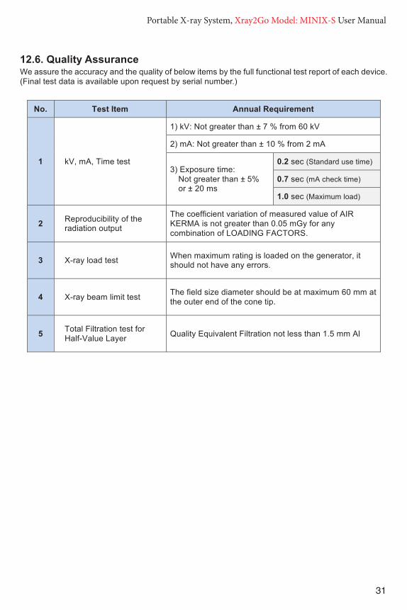
31
Portable X-ray System, Xray2Go Model: MINIX-S User ManualPortable X-ray System, Xray2Go User Manual
30
12.4. Optional Calibration Checks The Xray2Go is factory calibrated and tested prior to release (see the enclosed Final Inspection Report) and there are no adjustment options, A self-diagnostics is completed each time the device is powered up. However, the optional checks listed below may be performed by a qualified technician as desired. Setup a calibrated Performance Meter (such as the Victoreen NERO, mAx model 8000) according to manufacturer’s specifications to detect and report the following: X-ray Tube Voltage [kV Effective Mode], Radiation Time [ms Effective Mode], and Dose [mR Average Mode]. The filter card for the Test Detector should be in the 50-100kVp position. Final performance measurements are made using a NERO mAx, model 8000 X-ray meter from Victoreen. Tube current (mA) is sensed across a series connected resistor with an accuracy of ±1% and measured using a digital multimeter, prior to encapsulation; Xray2Go has no provision for external measurement of beam current after final manufacture. Exposure time is measured during the entire exposure; referenced to 75% rise/fall, using the NERO mAx 8000 X-ray meter. Accelerating voltage (kV) is measured at both peak (kVp) conditions and effective conditions (kVeff), which is the equivalent kV as if the kV were constant through the whole exposure time. Linearity is calculated per IEC 60601-2-65, 203.6.3.1.101
This X-ray unit may be dangerous to testing technician and any bystanders unless safe test exposure factors, such as placing the Test Detector in a lead lined box or the use of a protective lead apron are observed.
Enable the Xray2Go and, with the cone perpendicular to the test detector, make exposures into the Test Detector and capture the resulting data. And compare the result with the factory release parameters (indicated in the chart below). For results outside below tolerance limits, discontinue use and contact your dealer/distributor or DIGIMED.
Radiation Tolerance Limit
kV Accuracy Not greater than ± 10% from 60 kV 54 ~ 66 kV
mA Accuracy Not greater than ± 20% from 2 mA 1.6 ~ 2.4 mA
Exposure Time Accuracy Not greater than ± 5% or ± 20 ms 1.9 ~ 2.1 sec (5%)
12.5. Dosimetric Control The Xray2Go is factory tested with AIR KERMA for the selected LOADING FACTORS. As followed by the requirement of IEC EN, DAP Meter (Model: KermaX Plus TinO IDP) is used for the test. The overall deviation of the AIR KERMA from the estimated AIR KERMA does not exceed 50 %.
Portable X-ray System, Xray2Go User Manual
31
12.6. Quality Assurance We assure the accuracy and the quality of below items by the full functional test report of each device. (Final test data is available upon request by serial number.)
No. Test Item Annual Requirement
1 kV, mA, Time test
1) kV: Not greater than ± 7 % from 60 kV
2) mA: Not greater than ± 10 % from 2 mA
3) Exposure time: Not greater than ± 5% or ± 20 ms
0.2 sec (Standard use time)
0.7 sec (mA check time)
1.0 sec (Maximum load)
2 Reproducibility of the radiation output
The coefficient variation of measured value of AIR KERMA is not greater than 0.05 mGy for any combination of LOADING FACTORS.
3 X-ray load test When maximum rating is loaded on the generator, it should not have any errors.
4 X-ray beam limit test The field size diameter should be at maximum 60 mm at the outer end of the cone tip.
5 Total Filtration test for Half-Value Layer Quality Equivalent Filtration not less than 1.5 mm Al

32
Portable X-ray System, Xray2Go Model: MINIX-S User Manual
1) Parents must leave the room when x-rays are taken of their child.
a. True
b. False
2) How is the unit locked and secured when not in use?
a. Sitting on the counter in the exam room
b. Placed in a storage cabinet away from exam rooms
c. Locked in the case and place the keys in another location
3) When do you remove the backscatter shield?
a. Anytime it gets in the way
b. Never. It must stay affixed to the end of the cone for operator safety
4) What position should the backscatter shield be to the operator?
a. Perpendicular
b. Angled
c. Parallel
5) What is the meaning of ALARA?
a. As Low As Reasonably Achievable
b. As Little As Randomly Achievable
c. As Long As Rationally Alerted
6) What type of disinfectant should you use to clean the device?
a. Non-acetone and non-alcohol disinfectant wipes
b. Xylene
c. Rubbing alcohol
7) The correct way to hold the device is by the cone.
a. True
b. False
13 Operator Training TestName: _____________________________________________ Date: ___________
Results: Passed ❑ Failed ❑

33
Portable X-ray System, Xray2Go Model: MINIX-S User Manual
8) How would you change the radiology settings from adult to child?
a. • Press and hold the “S” button for 2 seconds • Press the power off button once • Press the “S” button to select child • Press and hold the “S” button for 2 seconds
b. Press the up arrow button, the down arrow button, then press OK
c. Press the up arrow button, then press OK
9) How would you change the exposure time?
a. Press the Up or Down arrow keys
b. Choose another tooth type
c. All of the above
10) What is displayed immediately after a full exposure?
a. “Xray2Go”
b. “READY”
c. “EXPOSURE”
11) How do you change the tooth type setting?
a. Press the up “^” button 3 times, then down ”v”, then OK
b. Press the down “v” button 3 times, then up “^”, then OK
c. Press and hold the “S” button for 2 seconds
Press the “S” button to select type
Press and hold the “S” button for 2 seconds
12) How do you resolve error codes?
a. Ask another technician for advice
b. Refer to the Error List in the User Manual
13) Required exposure times typically differ from film to sensor.
a. True
b. False
14) What will happen if a cell phone is used near Xray2Go?
a. A beeping signal will occur
b. An error message will appear
c. The device may autofire.

34
Portable X-ray System, Xray2Go Model: MINIX-S User Manual
15) What is the source to skin distance in accordance with FDA regulations?
a. A limit SSD to not less than 18 centimeters
b. A limit SSD to not less than 20 centimeters
16) The pistol grip is an accessory that is approved in my state for use.
a. True
b. False
17) This device is FDA approved and therefore we can ignore our state requirements.
a. True
b. False
18) Does your state department have any restrictions for a handheld x-ray device?
a. Yes
b. No
19) How do you register the Xray2Go with the state department?
a. Call the state department and let them know you have the Xray2Go.
b. Send a letter to the state health department on our letterhead and state that you have the Xray2Go.
c. Fill out an application from your state health department and send it in to them.
20) If your state department has restrictions for Xray2Go, please list the restrictions.
NOTE: Answers to Questions 16-20 will varies from state to state. The purchaser should go over their specific state requirements with their staff/employees.

35
Portable X-ray System, Xray2Go Model: MINIX-S User Manual
1. A
2. C
3. B
4. C
5. A
6. A
7. B
8. A
9. C
10. B
11. C
12. B
13. A
14. C
15. A
16. A or B ***
17. B.
18. A or B***
19. C.*** depends on each state’s regulation
14 Operator Training Test Answers

36
Portable X-ray System, Xray2Go Model: MINIX-S User ManualPortable X-ray System, Xray2Go User Manual
32
LIMITED WARRANTY
DIGIMED Co., Ltd. (DIGIMED hereunder) warrants the portable X-ray system, Xray2Go
to be free from any defects in material or workmanship for a period of one (1) years from
the date of purchase. (Battery: 12 months)
The liability of DIGIMED is limited repair or replacement of any parts that DIGIMED or its
authorized resellers determine to be defective. Parts proving defective will be repaired
or replaced free of charge, F.O.B. Seoul Korea (or the location of the authorized reseller),
if defective equipment is returned to such location for inspection, freight charges prepaid.
All warranty claims must be made not later than ten (10) business days following the
expiration of the applicable warranty period. Equipment repaired or replaced under
warranty will continue to be warranted for the balance of the original warranty term.
This warranty does not apply to equipment that is or has been abused, misused, or
altered (including opening enclosure or tampering), improperly maintained, subjected to
use beyond rated conditions, or damaged as a result of any carelessness or accidents.
This warranty does not cover ordinary wear and tear or maintenance.
DIGIMED makes no other warranty, either express or implied, with respect to any
equipment purchased from DIGIMED, including without limitation any implied warranties
of merchantability or fitness for a particular purpose, whether or not DIGIMED may have
been informed of the actual uses to which any of such equipment may be put. DIGIMED
shall not under any circumstance be liable for incidental, indirect, consequential, punitive
or exemplary damages, including without limitation damages for delay or lost profits, and
in no event shall liability of DIGIMED arising from the purchase, sale or use of the
equipment, or breach of any warranty made above, exceed in the aggregate the
purchase price paid therefore.

Portable X-ray System, Xray2Go User Manual
32
LIMITED WARRANTY
DIGIMED Co., Ltd. (DIGIMED hereunder) warrants the portable X-ray system, Xray2Go
to be free from any defects in material or workmanship for a period of one (1) years from
the date of purchase. (Battery: 12 months)
The liability of DIGIMED is limited repair or replacement of any parts that DIGIMED or its
authorized resellers determine to be defective. Parts proving defective will be repaired
or replaced free of charge, F.O.B. Seoul Korea (or the location of the authorized reseller),
if defective equipment is returned to such location for inspection, freight charges prepaid.
All warranty claims must be made not later than ten (10) business days following the
expiration of the applicable warranty period. Equipment repaired or replaced under
warranty will continue to be warranted for the balance of the original warranty term.
This warranty does not apply to equipment that is or has been abused, misused, or
altered (including opening enclosure or tampering), improperly maintained, subjected to
use beyond rated conditions, or damaged as a result of any carelessness or accidents.
This warranty does not cover ordinary wear and tear or maintenance.
DIGIMED makes no other warranty, either express or implied, with respect to any
equipment purchased from DIGIMED, including without limitation any implied warranties
of merchantability or fitness for a particular purpose, whether or not DIGIMED may have
been informed of the actual uses to which any of such equipment may be put. DIGIMED
shall not under any circumstance be liable for incidental, indirect, consequential, punitive
or exemplary damages, including without limitation damages for delay or lost profits, and
in no event shall liability of DIGIMED arising from the purchase, sale or use of the
equipment, or breach of any warranty made above, exceed in the aggregate the
purchase price paid therefore.
This Certifies that
HAS SUCCESSFULLY COMPLETED THE
OPERATOR TRAINING & SAFETYPROGRAM
AND IS THEREFORE AWARDED THIS
Certificate of TrainingDated
Supervising Physician

38
Portable X-ray System, Xray2Go Model: MINIX-S User Manual Portable X-ray System, Xray2Go User Manual
33
◈ Product Warranty & Registration Card ◈
Product name Portable Dental X-ray System
Model name Xray2Go
Serial number
Purchased date
Name of hospital or clinic
Address of hospital
Phone number
Name of distributor
Warranty period Product 1 years
Battery 12 months
DIGIMED Co., Ltd.
309~311, 318-ho, 145
Gasan digital 1-ro, Geumcheon-gu, Seoul, Korea
TEL.: +82-2-2624-1551 / FAX.: +82-2-2624-1553
www.digimed.co.kr
RAVAGNANI DENTAL Rua Delfim Ferreira, 580, 4100-199 Porto, Portugal TEL: 351-229-773-040
INNODEN LLC. 212 Wells Ave S. #102 Renton, WA 98057 USA TEL.: 425-572-0283 FAX: 425-988-1256
US Representative
ISO 13485
Certified Company

39
Portable X-ray System, Xray2Go Model: MINIX-S User ManualPortable X-ray System, Xray2Go User Manual
33
◈ Product Warranty & Registration Card ◈
Product name Portable Dental X-ray System
Model name Xray2Go
Serial number
Purchased date
Name of hospital or clinic
Address of hospital
Phone number
Name of distributor
Warranty period Product 1 years
Battery 12 months
DIGIMED Co., Ltd.
309~311, 318-ho, 145
Gasan digital 1-ro, Geumcheon-gu, Seoul, Korea
TEL.: +82-2-2624-1551 / FAX.: +82-2-2624-1553
www.digimed.co.kr
RAVAGNANI DENTAL Rua Delfim Ferreira, 580, 4100-199 Porto, Portugal TEL: 351-229-773-040
INNODEN LLC. 212 Wells Ave S. #102 Renton, WA 98057 USA TEL.: 425-572-0283 FAX: 425-988-1256
US Representative
ISO 13485
Certified Company

Digital Doc LLC.4789 Golden Foothill Parkway
El Dorado Hills, CA 95762www.digi-doc.com