user manual dillenger mid drive electric bike kit bbs ...… · user manual dillenger mid drive...
TRANSCRIPT

CONVERSION KIT
Please read through carefully before beginning your conversion
User ManualDillenger Mid Drive Electric Bike KitBBS Bafang Mid DriveBBS01, BBS02, BBSHD
English

2
SAFETY
PLEASE NOTE
Mechanical Safety Check:Routinely check the condition of your bike. Make sure no fasteners have come loose. Perform a visual inspection of the whole bicycle before every ride. Make sure tyres are correctly inflated within the range given on the tyre sidewall. Check your brakes for proper operation.
Your First Ride:Be sure to pick an area away from cars, other cyclists, obstacles or other hazards to become familiar with the controls, features and performance of your new electric bike.
Installation Difficulty:It is possible, as all bikes are manufactured differently, that certain components of your bike may remove or install differently and/or contain different steps. However we have used a bike that is quite universal to demonstrate all the processes involved in the installation of this conversion kit. If you encounter any trouble we urge you to contact us at Dillenger for further assistance.
We highly recommend purchasing the Dillenger Electric Bike Conversion BBS Toolkit. It will make your installation and ongoing maintenance much easier. This can be purchased online at www.dillengerelectricbikes.com.au
Thank you for purchasing your new Dillenger conversion kit! We know you’ll love it, and with some care it should last for a very long time. Please read through this manual carefully before operating the kit.
THANK YOU
This manual uses the BBS HD for installation steps, however most steps are the same across the board for the BBS 01, 02 and HD. If you encounter any installation difficulties please contact us.
3
Thank You 2
Safety 2
Item Check List 4
Installation Overview 5
Toolkit 6
Toolkit Checklist 7
Installation Process 8
Crank Removal 8
Bottom Bracket Removal 10
Front Derailleur Removal 11
Motor Installation 12
Crank Installation 14
Battery/ Battery Cradle Installation 15
Thumb Throttle Installation 16
Display Installation 17
E-Brakes Sensors Installation 18
Pedal Assist Sensor Installation 19
Gear Sensor Installation 20
Wiring Installation 22
Tidy Up 24
Battery Operation 25
Turning Your Bike On/Off 25
Charging 26
Maintenance and Care 27
Trouble Shooting 28
Contact Us 32
CONTENTS

4
ITEM CHECK LISTEach conversion kit is tested for quality control before shipping to a customer. Before converting your bike, it’s a good idea to lay each of the components out to visiualise how they will come together on your bicycle.
● Before you begin your conversion, it can be helpful to lay everything out first and make sure all the parts are there.
● Something missing? Double check the box, even under the flaps. Those small parts can be sneaky. If you still can’t find it let us know and we’ll assist you ASAP.
Motor/ Cranks
Thumb Throttle
Battery/ Cradle
Pedal Assist Sensor/ Magnet
Charger
Display
Gear Sensor Wiring Loom

5
INSTALLATION OVERVIEW
Remove ContentsTake your components out of the box. Remove the protective packaging. Keep track of all the parts that you remove from the box. Remove the battery and put it on charge.
1.
InstallationOnce your bike has had any necessary preparation steps completed, this manual will step through the installation of each component within the conversion kit.
3.
Ride!Once the battery is fully charged, you’ve checked your tyre pressures and fasteners you’re now ready to go!
5.
Prepare Your bikeBefore installing certain components of the kit, your bike may need some initial preperation such as removing some existing components. This manual will walk through general guidelines of this bike preparation that should apply to most bikes.
2.
Tidy UpAfter you have installed all of the components needed to control each part of the kit, it’s now time to tidy up the wiring harness and make your conversion look nice and neat.
4.

6
TOOLKITHere at Dillenger, we offer toolkits that come with all the tools you need to install the conversion kits properly. This toolkit is shown below and is available online at www.dillengerelectricbikes.com.au
We recommend you purchase one of these kits along with any of the BBS conversion kits, as it is highly important to use the correct tools when removing your existing cranks/ bottom bracket, and will be extremely difficult to complete without these tools. Worst case scenario would be the possible damaging of components from using the incorrect tools.

7
TOOLKIT CHECK LISTThe tools included in the BBS toolkit are displayed below. Each tool has a purpose within the steps of this installation and you will see the specific tools mentioned during the steps that require a particular tool.
Allen Key Set
Bottom Bracket Lock Ring Tool
Multi Sized Spanner
Socket Wrench Ratchet
8FUN Lock Ring Tool
Crank Removal Tool
Shifting Spanner Bottom Bracket Removal Tool
Phillips Head Screw Driver
8
INSTALLATION PROCESS
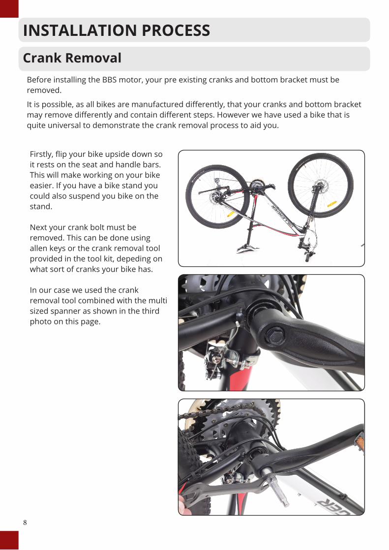
Before installing the BBS motor, your pre existing cranks and bottom bracket must be removed.
It is possible, as all bikes are manufactured differently, that your cranks and bottom bracket may remove differently and contain different steps. However we have used a bike that is quite universal to demonstrate the crank removal process to aid you.
Crank Removal
Firstly, flip your bike upside down so it rests on the seat and handle bars. This will make working on your bike easier. If you have a bike stand you could also suspend you bike on the stand.
Next your crank bolt must be removed. This can be done using allen keys or the crank removal tool provided in the tool kit, depeding on what sort of cranks your bike has.
In our case we used the crank removal tool combined with the multi sized spanner as shown in the third photo on this page.

9
Crank Removal Continued
Now the black portion of the crank removal tool should be threaded into the crank as shown in photo 1.
Next insert the silver part of the crank removal tool into the black part, as shown in photo 2, and using the multi sized spanner, continue to thread the silver portion in untill it forces the crank to pop off the spindle.
You should now have a clear spindle with no crank. As shown in photo 3.
This process can be followed to remove the crank from the other side of the bike as well.

10
The next step is to use the bottom bracket removal tool in conjuction with the ratchet to remove the bottom bracket cups.
Photo 2 shows how to insert this tool into the bottom bracket cup, then the bottom bracket cup must be loosenedusing the ratchet until it can be removed.
This should also be done to the bottom bracket cup on the other side of your bike, which should leave your bottom bracket on the frame empty as in photo 4 of this page, ready to insert the BBS motor.
Bottom Bracket Removal

11
The front derailleur and front gear cables now need to be removed. If your bike does not have a front derailleur/ front gears you can skip this step.
The front derailleur can normally be removed from the frame by simply loosening one allen key bolt. The clamp on the derailleur should unhinge in order to take it off the frame.
Now we are confronted with a tricky part. You will find that the chain goes through the front derailleur.
If you don’t care about the front derailleur, as it is not needed in the BBS motor conversion, you can simply cut the derailleur in order to remove the chain.
If you would like to keep the front derailleur as a spare part, then you must remove your chain.
This can be done easily if your chain has a quick link.
If not, you may have to break the chain using a chain breaker, as shown in photo 3.
If any of these steps seem to difficult for you, please contact us at Dillenger or a reputable bike mechanic.
Remove the cables associated with the front derailleur that was just removed.
Reinstall the chain, with the front derailleur removed and we are now ready to move on to the motor installation.
Front Derailleur Removal

12
Motor InstallationNow that the bike is ready to have the motor installed, the motor and its parts should be disassembled as shown to the right in photo 1. The components you have for this motor installation are the main motor, two cranks, two crank bolts, 8FUN locking nut, bottom bracket locking nut and the fixing plate that has two bolts.
The first step of the installation is to slide the shaft of the motor into the bottom bracket of the frame as shown in photo two.
Photo three shows how the motor should be pressed up against the down tube of your frame before tightening all the motor’s fasteners. Make sure any cables that run along the down tube of your frame are clear from being clamped down by the motor as this could cause these brake/gear cables to fail.
The next step is to put the fixing plate onto the motor shaft and tighten down the two bolts through the spacer and into the motor body as shown in the last photo.

13
Motor Installation Continued
The bottom bracket lock ring should now be threaded on to the motor axle.
This lock ring should be tightened to 50-60 Nm of torque using the bottom bracket lock ring tool as shown to the right in photo 2.
Now the 8FUN lock ring can be threaded on to the motor axle.
This lock ring should be tightened to 25-30 Nm of torque using the 8FUN lock ring tool as shown in photo 4 of this page.
The motor installation is now complete.

14
Crank Installation
BBS kits come with a new set of cranks, these simply slip onto the motor axle.
The crank bolts supplied with this kit should be inserted as they are shown in photo 1, and then tightened with an allen key as shown in photo 2.
Your pedals can now be reinstalled using the multi sized spanner included in the BBS tool kits. Most pedals will have a 15mm spanner size.
Lastly your chain should be put onto the motor sprocket as shown in the photos at the bottom of this page.
The rest of the installation operations can be carried out while the bike is standing upright on its wheels.

15
Battery/ Battery Cradle Installation
This kit comes complete with a custom built battery cradle that interfaces with the drink bottle holder holes in the downtube of your frame and allows you to securely lock the battery into place.
To start, make sure you have separated the battery from its cradle as shown in photo 1.
Next, make sure you have removed the two bolts where the drink bottle holder goes, shown in photo 2. Finally, align the slots in the cradle with the holes in the frame. Insert the two bolts through the cradle into the frame as shown in photo 3. The cradle can now be slid up and down the down tube to find the most optimum position. Once this is done, tighten the two bolts and slot the battery in it’s cradle. The completed battery and cradle installation can be seen in photo 4. Turn the key in the battery to lock it in place.

16
Thumb Throttle Installation
Start by loosening both brake levers and sliding them into the centre of your handle bars as shown in photo 1. This will give you room to install the controls that are included in this conversion kit.
Next, slide the thumb throttle onto your handlebars, usually the right side, however it is up to personal preference which side the throttle goes. Move the throttle so that it sits flush against the brake lever and tighten it in place.
Once you have the throttle secured, make sure the cable is not fouling the brake lever, otherwise readjust.
Make sure you insert the small plastic bush (you can see this in the third photo on this page) after installing the throttle. This prevents the grip from rubbing against the throttle.
Once the throttle and brake lever are in a comfortable position tighten your brake lever.
PLEASE NOTEFor users in states or territories that require no hand throttle to be used, (pedal assist only), you can pass this step and leave the throttle absent. Please move onto the RPAS installation process.

17
Display Installation
Mounting the display is easy. The display should be mounted to the clamp first, using two screws.
Next, remove the nuts and bolts from the clamp and put the clamp on the handlebars.
There are rubber spacers included in the kit that go inside the clamp depending on the thickness of your handlebars. Now put the nuts and bolts back into the clamp and tighten them securely.
Position the display so that it will be hassle free to glance at during your ride.
The angle of the display can depend on the rider style or the shape of the handle bars.
Attached to the Display is also a Pedal Assist Controller. This Controller also has the On/Off button on it.
The way this controller works is that it has a number rating that will appear on screen. The higher the number, the more that the motor will assist with your riding, or pedaling.
This pedal assist controller should be slid on to the handlebars on the side most preffered by the rider and then tightened in a comfortable position. This is shown in photo 2.
Tighten your brake lever in place, and do a final check of all the controls that they are all comfortable and tightened.
The grips can now be reinstalled to your handlebars.
18
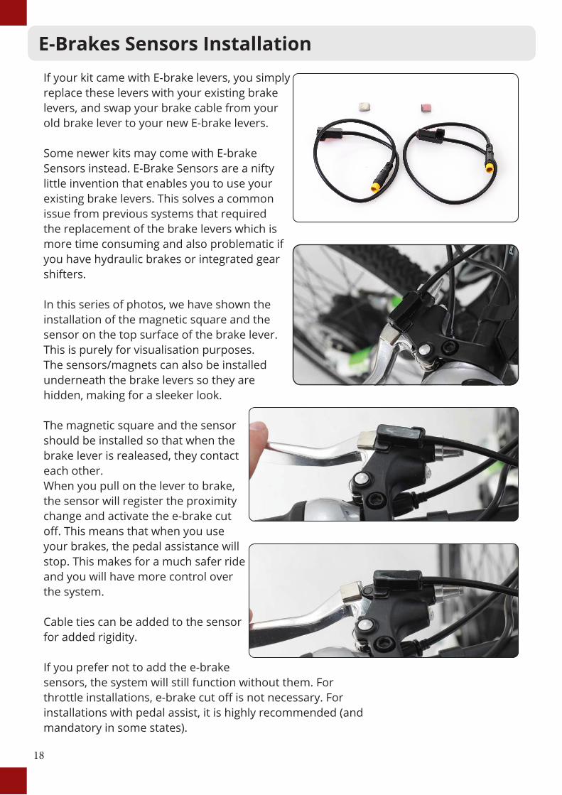
E-Brakes Sensors InstallationIf your kit came with E-brake levers, you simply replace these levers with your existing brake levers, and swap your brake cable from your old brake lever to your new E-brake levers.
Some newer kits may come with E-brake Sensors instead. E-Brake Sensors are a nifty little invention that enables you to use your existing brake levers. This solves a common issue from previous systems that required the replacement of the brake levers which is more time consuming and also problematic if you have hydraulic brakes or integrated gear shifters.
In this series of photos, we have shown the installation of the magnetic square and the sensor on the top surface of the brake lever. This is purely for visualisation purposes. The sensors/magnets can also be installed underneath the brake levers so they are hidden, making for a sleeker look.
The magnetic square and the sensor should be installed so that when the brake lever is realeased, they contact each other. When you pull on the lever to brake, the sensor will register the proximity change and activate the e-brake cut off. This means that when you use your brakes, the pedal assistance will stop. This makes for a much safer ride and you will have more control over the system.
Cable ties can be added to the sensor for added rigidity.
If you prefer not to add the e-brake sensors, the system will still function without them. For throttle installations, e-brake cut off is not necessary. For installations with pedal assist, it is highly recommended (and mandatory in some states).

19
Pedal Assist Sensor Installation
Firstly, install the pedal assist sensor on your frame as shown in photo 1, using the sticky adhesive that is on the base of the sensor. The sensor should then be zip tied in place to make sure it is secure.
The magnet should be loosened apart and then placed onto a spoke and tightened so that the magnet will be opposite and parallel of the sensor as shown in photo 4.
The purpose of the pedal assist sensor is to generate a signal from the rotation of the wheel that the controller then processes to know that you’re pedaling and want some power!
The level of assistance you receive is controlled by your handle bar display buttons, which we already fitted with the display, (up and down buttons).

Gear Sensor Installation
This unique patent pending system developed and made in Czech Republic is based on the intelligent GearSensor fixed on the shifting cable, which cuts off the motor drive when the rider activates gearshifting. This brand new technical solution eliminates user-unfriendly and noisy rear derailleur shifting which is caused by chain over straining.
As the rear derailleur shown to the right is the most common type of gears, we have chosen to demonstrate the installation steps of this type of rear derailleur. If you are installing this conversion kit on a bike with internal gears, there is a separate GearSensor manual on the Dillenger website that covers this installation process. However the same concept is involved for both the rear derailleur and internal gear installations.
Photo 1 shows where the GearSensor should be installed. The aim is to place the gear sensor within the rear derailleur cable. The cable should be kept the same length. Some material needs to be cut out so that the gear sensor can take its place. This is covered on the next page.
The first step is to remove your gear cable using allen keys. The rear derailleur with the cable removed is shown in photo 2.
20

Gear Sensor Installation Continued
In this first photo you can see the gear cable removed and the GearSensor in place for visualisation.
The next step is to cut about 50mm (the length of the GearSensor) out of your gear cable, as can be seen in photo 2.
Now that 50mm you cut out can be discarded, and replaced by the GearSensor as shown in photo 3.
The inner gear cable should now be fed back through the outer cable and through the GearSensor, and then reinstalled by tightening the inner cable back to the rear derailleur with an allen key.
As long as you tighten the inner cable in the position that it was in previously, and the overall length of the cable including the GearSensor is the same as the cable length before installing the GearSensor, then the gears should continue to function as they did before without any furhter adjustment.
21

22
Wiring Installation
The wiring now has to be connected up so that everyhting has power and can function correctly.
All the wires are colour coded so it is simply a matter of connecting the same coloured wire ends together.
1. The first wire to connect is the main wire connecting from the controller to the battery. This wire has two pins at the end as shown in the first photo. At the end of the wires are arrows, align the arrows and then insert the pins.
2. The next wire to join is from the motor to the GearSensor. These wires are colour coded yellow as shown in photo 2.
3. Then wire the pedal assist sensor to the motor. This wire as shown in photos 3 and 4 has a plastic cap that threads on after inserting the wires, to ensure a tight connection.

23
Wiring Installation Continued
4. Now connect the Wiring Loom to the motor. These wires are colour coded with a black end plug shown in photos 1 and 2 on this page.
5. One of the yellow plugs from the wiring loom goes to the throttle.
6. The green plug from the wiring loom joins with the wire coming from the Display monitor.
7. Lastly the two left over yellow plugs will connect to the E-brakes.

24
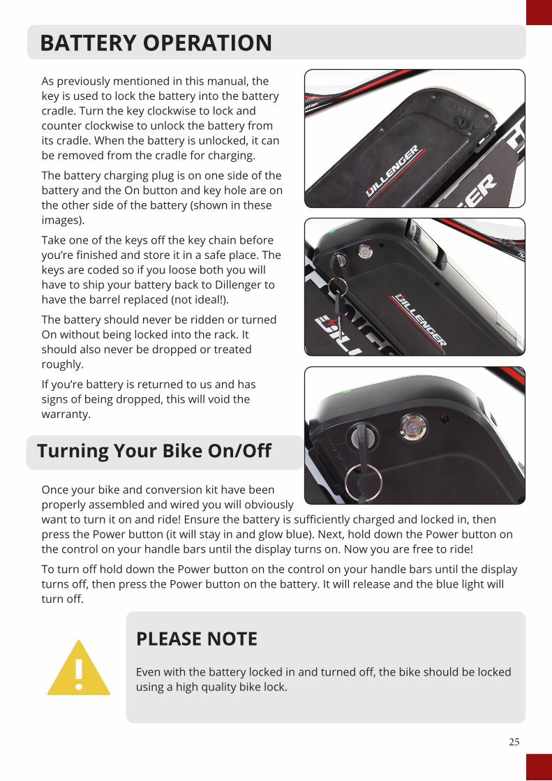
As previously mentioned in this manual, the key is used to lock the battery into the battery cradle. Turn the key clockwise to lock and counter clockwise to unlock the battery from its cradle. When the battery is unlocked, it can be removed from the cradle for charging.
The battery charging plug is on one side of the battery and the On button and key hole are on the other side of the battery (shown in these images).
Take one of the keys off the key chain before you’re finished and store it in a safe place. The keys are coded so if you loose both you will have to ship your battery back to Dillenger to have the barrel replaced (not ideal!).
The battery should never be ridden or turned On without being locked into the rack. It should also never be dropped or treated roughly.
If you’re battery is returned to us and has signs of being dropped, this will void the warranty.
Once your bike and conversion kit have been properly assembled and wired you will obviously want to turn it on and ride! Ensure the battery is sufficiently charged and locked in, then press the Power button (it will stay in and glow blue). Next, hold down the Power button on the control on your handle bars until the display turns on. Now you are free to ride!
To turn off hold down the Power button on the control on your handle bars until the display turns off, then press the Power button on the battery. It will release and the blue light will turn off.
In the final stage of the installation, it’s time to tidy up the wires and make everything look nice and neat.
In the adjacent images, you can see the provided zip/cable ties being used to bundle and secure the cables coming from the base of the battery/motor, pedal assist sensor, GearSensor, wiring loom and anything else leading up to the handlebars.
Also included in most kits is a protection pipe which can be used to group multiple brake/gear cables together to make for a neater appearance.
The installation is now complete, and your bike is ready to ride!
TIDY UP
25
PLEASE NOTEEven with the battery locked in and turned off, the bike should be locked using a high quality bike lock.
As previously mentioned in this manual, the key is used to lock the battery into the battery cradle. Turn the key clockwise to lock and counter clockwise to unlock the battery from its cradle. When the battery is unlocked, it can be removed from the cradle for charging.
The battery charging plug is on one side of the battery and the On button and key hole are on the other side of the battery (shown in these images).
Take one of the keys off the key chain before you’re finished and store it in a safe place. The keys are coded so if you loose both you will have to ship your battery back to Dillenger to have the barrel replaced (not ideal!).
The battery should never be ridden or turned On without being locked into the rack. It should also never be dropped or treated roughly.
If you’re battery is returned to us and has signs of being dropped, this will void the warranty.
Turning Your Bike On/Off
Once your bike and conversion kit have been properly assembled and wired you will obviously want to turn it on and ride! Ensure the battery is sufficiently charged and locked in, then press the Power button (it will stay in and glow blue). Next, hold down the Power button on the control on your handle bars until the display turns on. Now you are free to ride!
To turn off hold down the Power button on the control on your handle bars until the display turns off, then press the Power button on the battery. It will release and the blue light will turn off.
BATTERY OPERATION

26
PLEASE NOTEOnly charge the batteries with the specified charger. Using a different charger could damage your battery.
Charging the battery:
1. Plug the charger into the wall socket/outlet, just like a laptop of mobile phone charger.
2. Check that one of the charger indicator lights glows green
3. Plug the charger, (battery end) into the battery carefully, making sure it is all the way in. Do not force it if there is an obstruction.
4. The charger indicator lights should glow red whilst charging.
5. Once the charger indicator lights change to 1 red and 1 green, the battery is fully charged.
There is no way to over-charge the battery. When it is full, the charger will stop charging the battery automatically.
Charging time can vary from 1 to 5 hours if fully empty.
The battery should be charged once every month as a minimum to maintain healthy cells.
The best way to charge your battery is to plug it in after every use, and leave it on charge until the indicator light shows the battery is fully charged. It is not good practice to only half or partially charge the battery.
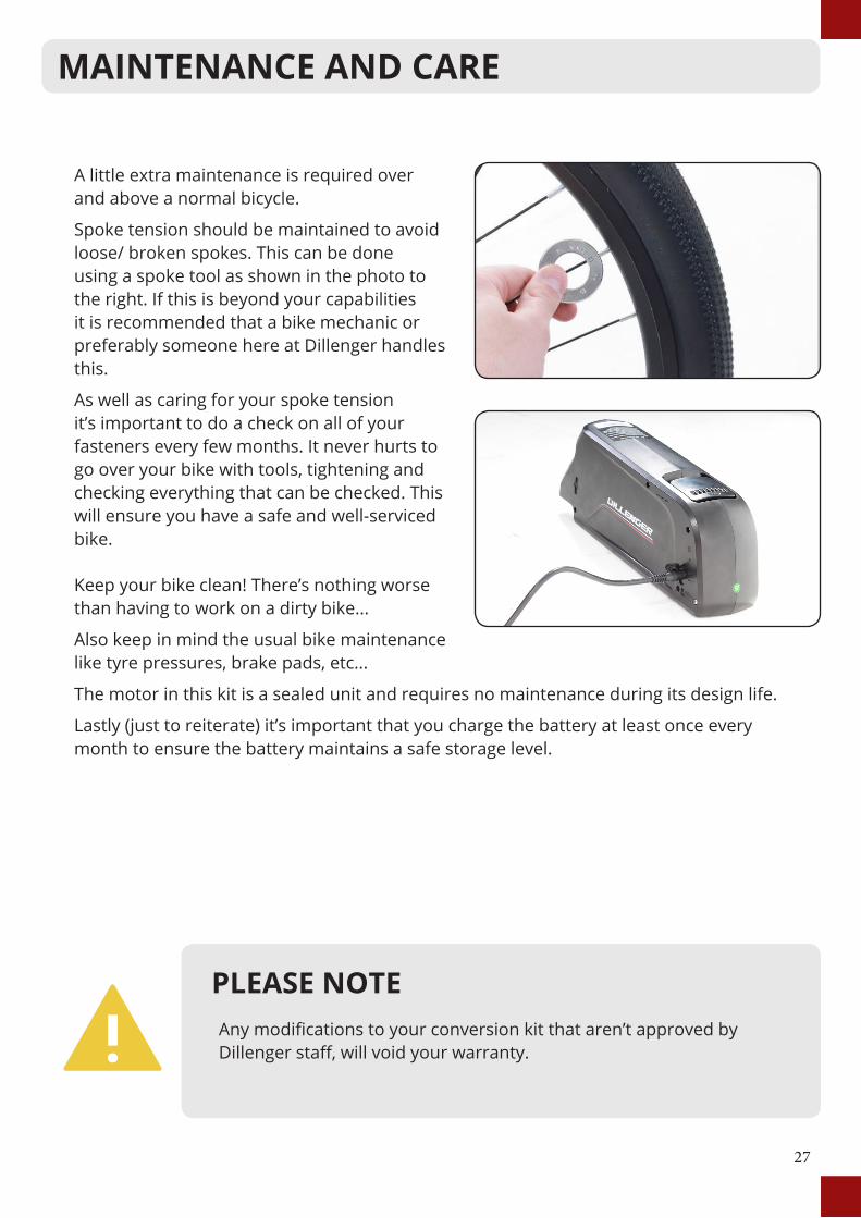
A little extra maintenance is required over and above a normal bicycle.
Spoke tension should be maintained to avoid loose/ broken spokes. This can be done using a spoke tool as shown in the photo to the right. If this is beyond your capabilities it is recommended that a bike mechanic or preferably someone here at Dillenger handles this.
As well as caring for your spoke tension it’s important to do a check on all of your fasteners every few months. It never hurts to go over your bike with tools, tightening and checking everything that can be checked. This will ensure you have a safe and well-serviced bike.
Keep your bike clean! There’s nothing worse than having to work on a dirty bike...
Also keep in mind the usual bike maintenance like tyre pressures, brake pads, etc...
The motor in this kit is a sealed unit and requires no maintenance during its design life.
Lastly (just to reiterate) it’s important that you charge the battery at least once every month to ensure the battery maintains a safe storage level.
CHARGING
27
PLEASE NOTEAny modifications to your conversion kit that aren’t approved by Dillenger staff, will void your warranty.
A little extra maintenance is required over and above a normal bicycle.
Spoke tension should be maintained to avoid loose/ broken spokes. This can be done using a spoke tool as shown in the photo to the right. If this is beyond your capabilities it is recommended that a bike mechanic or preferably someone here at Dillenger handles this.
As well as caring for your spoke tension it’s important to do a check on all of your fasteners every few months. It never hurts to go over your bike with tools, tightening and checking everything that can be checked. This will ensure you have a safe and well-serviced bike.
Keep your bike clean! There’s nothing worse than having to work on a dirty bike...
Also keep in mind the usual bike maintenance like tyre pressures, brake pads, etc...
The motor in this kit is a sealed unit and requires no maintenance during its design life.
Lastly (just to reiterate) it’s important that you charge the battery at least once every month to ensure the battery maintains a safe storage level.
MAINTENANCE AND CARE

28
Dillenger’s troubleshooting advice will take you through a logical way to diagnose any issues that may arise during installation and use.
Before commencing troubleshooting, disconnect all components. Do not short cut this process. There are countless times a loose plug has caused grief. By disconnecting all the plugs and then reconnecting just the crucial components, this will solve any loose plug issue.
Go through one by one plugging in the other components (such as the pedal assist sensor or the e-brake handles) to see if any of these are the cause of the problem. In this basic state you may discover the culprit quickly.
Fault Solution
Display turns on, but motor does not Activate
Check the motor plug from the controller. This is a very stiff connection and will not work unless the plug is all the way in to the indicator line. The twisting of the handlebars can sometimes cause the plug to pull out slightly if there is not enough slack in the motor cable.
Motor runs backwards Remove the motor from the frame and switch the direction.
Display won’t turn on, unless the battery charger is plugged in
Check all the connections, make sure the battery is charged. If the display turns on only when the battery charger is plugged in, you will have to submit a service ticked with this information.
A high pitched rattling noise can be heard when accelerating
The vibration of the motor is very small, but at this frequency it can do some odd things to the other components on the bike if they are loose. For example a loose spoke or even a bolt on your rear rack. If something is just a little bit loose, sometimes this can reverberate and make a harsh high pitch rattling sound. Nothing is broken or wrong, you just have to identify the loose part!
Rim has a buckle or spokes coming loose all the time
We would recommend a competent wheel builder to fix any major spoke tension issues, however there are some really good youtube tutorials on how to adjust spoke tension.
Spokes have snapped or missing
Dillenger stocks spare spokes for very reasonable prices, just check out our spares section online and you can find the right type and length for your kit.
TROUBLE SHOOTING

Fault Solution
Motor does not fit in the bottom bracket
Any bike with an internal bottom bracket between 68 and 73mm wide will be compatible with this kit. If the bottom bracket has any small defects like a bur or foreign particle in the way, you may need to use a file to smooth these out. The mid drive kit requires a very good fit and this can make it quite stiff to install, but it will fit!
Motor does not fit in the bottom bracket (cont.)
Unfortunately there are always going to be rare cases when a manufacturer of a bike has decided to be different. If this is the case and there is not enough thread extending out the other side of your bottom bracket (requires 10mm+) or the motor simply won’t slide into your bottom bracket if the diameter is too small, you may have to seek assistance from a bicycle mechanic or preferably, us here at Dillenger. The motor spindle that slides into your frame bottom bracket has a diameter of approximately 33.3 mm so your bottom bracket should also have a diameter around this value.
Wiring to a part of the kit is not long enough
For this problem we stock a wiring extension kit which can be purchased online. This is usually recommended for rear rack versions of this kit.
Drink bottle holder bolts won’t tighten
You may require some longer bolts. The bolts should thread into your frame a reasonable amount as they will be holding the battery to the frame and this connection should be as structur-ally sound as possible. If you feel as though the bolts aren’t long enough, please get some longer bolts as using bolts that are too small may cause the thread to strip.
Handlebar too crowded
If for instance you have integrated shifters, you might find that with the throttle and shifter on the right side, you have run out of room. If you can’t manage to shuffle everything around to make room, you may prefer to opt for a thumb throttle, which is available for purchase from Dillenger online.
I have hydraulic brakes, or integrated shifters and brakes
If the e-brakes provided are not ideal, either you can elect not to use e-brake handles (the kit will still function) or you purchase from Dillenger e-brake cut-off sensors which can mount to your existing brake handles, no matter what kind.
I don’t want to use the pedal assist, or don’t want to use throttle
The controller is configured so you can run both the pedal as-sist sensor, and the throttle, or one or the other. If installed, the throttle will always act as an override.
29
TROUBLE SHOOTING CONTINUED...

Fault Solution
Kit won’t turn on at all
Get a hold of a multimeter ($15 on ebay) and test the voltage (DC) output from the base of the battery. If this isn’t over 41V on a 36V kit, then the battery may have to be returned to Dilleng-er for testing and potential replacement. If this is not the issue, then please double check the connections. With reasonable volt-age, the kit should turn on if there is no fault with the display.
Error message on the display
Please refer to display manual for error code definition and if needed, report the error code to Dillenger in a service ticket.
My kit looses power over bumps
Check all connections to make sure all the plugs are all the way connected. Check that the battery is locked to the cradle and not loose. A momentary discontinuity in power will turn the kit off.
My battery cuts out intermittently
If the battery is low on power, or you are going up a very steep hill with a load on the motor, you will likely experience a voltage cut-off if you have overloaded the controller, or dropped the voltage below the low voltage cut-off, which is more prevalent at low power. This isn’t a fault with the kit, it’s just physics.
I would like my battery capacity tested
Please contact Dillenger by submitting a support ticket toarrange the return of your battery for testing. If the battery tests above 85% capacity within the first year (from purchase date) you will be liable for return freight. If it is tested and is under capacity within the warranty period, your battery will be replaced.
My range has degraded See next page.
Range extension:
If you’re not getting the approximate quoted range out of your e-bike system, take the following steps:
1. Pedal Assist Sensor
If you haven’t installed the pedal assist sensor, you might not get the required range out of your kit. The pedal assist modes only work for pedal assist input, not throttle. If you use the throttle on low levels of pedal assist, this will not make any difference. Pedal assist levels are only for pedal assist. The throttle is great fun to use, but even moderate use of the throttle, with pedaling, is still going to burn through the juice a lot faster than on a low-medium pedal assist setting.
2. Battery Indicator Lights – Full Charge. The LED and LCD battery level displays are a basic indication of battery charge, but they are based on voltage which is variable and not a true indication of battery capacity. The only accurate indication of a full charge, is having charged the battery and the battery charger lights glowing green to indicate that the battery is fully charged.
3. LED/LCD Indicator Light – Running Low
Some customers find that the LED/LCD charge indicator can lead them astray in terms of how far the bike will go on low power. You don’t risk damaging the system by riding all the way to the controller low voltage cutoff. Keep riding on pedal assist even after the last battery indicator bar starts blinking.
4. Hills/ Riding Style/ Other Factors
The ranges quoted are from real world testing, with some hills and some flat areas. If your commute involves a lot of hills, that’s going to impact on the range of the kit. 1,000W kits are especially susceptible to being drained a lot more on hills (more than 250W kits anyway). If you need to purchase a second charger to charge the battery at half way, or if you need an additional battery, they will be available for purchase online.
5. General Tips
• Make sure the wheels are running free (rubbing brakes can halve your range quite easily)
• Keep the battery topped up between uses
• Make sure the tyre pressures are at optimum
• Pedal harder when taking off and select the right gear for assisting up hills
If you would like to submit a Dillenger service ticket, please go to this URL:
https://dillenger.zendesk.com/hc/en-us/requests/new
30
TROUBLE SHOOTING CONTINUED...
Range extension:
If you’re not getting the approximate quoted range out of your e-bike system, take the following steps:
1. Pedal Assist Sensor
If you haven’t installed the pedal assist sensor, you might not get the required range out of your kit. The pedal assist modes only work for pedal assist input, not throttle. If you use the throttle on low levels of pedal assist, this will not make any difference. Pedal assist levels are only for pedal assist. The throttle is great fun to use, but even moderate use of the throttle, with pedaling, is still going to burn through the juice a lot faster than on a low-medium pedal assist setting.
2. Battery Indicator Lights – Full Charge. The LED and LCD battery level displays are a basic indication of battery charge, but they are based on voltage which is variable and not a true indication of battery capacity. The only accurate indication of a full charge, is having charged the battery and the battery charger lights glowing green to indicate that the battery is fully charged.
3. LED/LCD Indicator Light – Running Low
Some customers find that the LED/LCD charge indicator can lead them astray in terms of how far the bike will go on low power. You don’t risk damaging the system by riding all the way to the controller low voltage cutoff. Keep riding on pedal assist even after the last battery indicator bar starts blinking.
4. Hills/ Riding Style/ Other Factors
The ranges quoted are from real world testing, with some hills and some flat areas. If your commute involves a lot of hills, that’s going to impact on the range of the kit. 1,000W kits are especially susceptible to being drained a lot more on hills (more than 250W kits anyway). If you need to purchase a second charger to charge the battery at half way, or if you need an additional battery, they will be available for purchase online.
5. General Tips
• Make sure the wheels are running free (rubbing brakes can halve your range quite easily)
• Keep the battery topped up between uses
• Make sure the tyre pressures are at optimum
• Pedal harder when taking off and select the right gear for assisting up hills
If you would like to submit a Dillenger service ticket, please go to this URL:
https://dillenger.zendesk.com/hc/en-us/requests/new
31
TROUBLE SHOOTING CONTINUED...

32
Dillenger HQ
CONTACT US
3/13 Olympic CircuitSouthportQLD 4215AUSTRALIAPhone: 07 5532 9235dillenger.zendesk.comwww.dillengerelectricbikes.com.au
© Dillenger 2016