user manual - emerson electric...4 disclaimer transit damage is essentially an insurance claim and...
TRANSCRIPT
Copeland Scroll™
ZXV Variable speed condensing unit for refrigeration applications
User manual

Emerson is pleased to offer the ZXV/ZXLV variable speed condensing units from ZX platform, especially designed for refrigeration applications.
Overall, ZX platform CDU (ZX and ZXBmedium temperature, ZXL low temperature,ZXD/ZXLD digital modulated capacity medium temperature and low temperature, ZXV/ZXLV variable speed medium temperature and low temperature refrigeration) has been highly successful in the Asian market and enjoys proven success with its energy savings and customer-friendly electronic features.
ZXV condensing unit
Table of contents
Disclaimer 04
Features and benefits 05
Nomenclature 05
Bill of material 05
Physical layout of the unit 06
ZXV Product specification 08
Qualified refrigerants and oils 08
Operating envelopes 08
Performance data 09
Technical data 11
CoreSense™ controller 12
Network wiring 17
Installation 19
Condensing unit handling 19
Electrical connection 19
Refrigeration piping installation 20
Liquid line insulation 20
Brazing recommendations 20
Location and fixing 21
Start up and operation 21
Vacuuming 21
Charging procedure 21
Check before starting & during operation 22
ZXV do’s and don’ts 22
Alarm codes 23
Wiring diagrams 27
Temperature sensor resistance 27
Contact lists 32
4
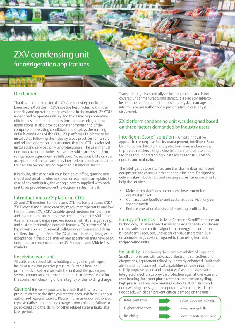
Disclaimer
Thank you for purchasing the ZXV condensing unit from Emerson. ZX platform CDUs are the best in class within the capacity and operating range available in the market. ZX CDU is designed to operate reliably and to deliver high operating efficiencies in medium and low temperature refrigeration applications. It also provides constant monitoring of the compressor operating conditions and displays the running or fault conditions of the CDU. ZX platform CDUs have to be installed by following the industry trade practices for its safe and reliable operation. It is assumed that the CDU is selected, installed and serviced only by professionals. The user manual does not cover good industry practices which are essential on a refrigeration equipment installation. No responsibility can be accepted for damage caused by inexperienced or inadequately trained site technicians or improper installation design.
If in doubt, please consult your local sales office, quoting unit model and serial number as shown on each unit nameplate. In case of any ambiguity, the wiring diagram supplied with each unit takes precedence over the diagram in this manual.
Introduction to ZX platform CDUZX and ZXB medium temperature, ZXL low temperature, ZXD/ZXLD digital modulated capacity medium temperature and low temperature, ZXV/ZXLV variable speed medium temperature and low temperature series have been highly successful in the Asian market and enjoys proven success with its energy savings and customer-friendly electronic features. ZX platform CDUs have been applied by several well-known end-users and chain retailers throughout Asia. The ZX platform is also gaining wider acceptance in the global market and specific variants have been developed and exported to the US, European and Middle East markets.
Receiving your unitAll units are shipped with a holding charge of dry nitrogen inside at a low but positive pressure. Suitable labeling is prominently displayed on both the unit and the packaging. Service connectors are provided on the CDU service valve for the convenient checking of the integrity of the holding charge.
Caution! It is very important to check that this holding pressure exists at the time you receive each unit from us or our authorized representatives. Please inform us or our authorized representative if the holding charge is non-existent. Failure to do so could void the claim for other related system faults at a later period.
Transit damage is essentially an insurance claim and is not covered under manufacturing defect. It is also advisable to inspect the rest of the unit for obvious physical damage and inform us or our authorized representative in case any is discovered.
ZX platform condensing unit was designed based on three factors demanded by industry users
Intelligent Store™ solution - A most innovative approach to enterprise facility management, Intelligent Store by Emerson architecture integrates hardware and services, to provide retailers a single view into their entire network of facilities and understanding what facilities actually cost to operate and maintain.
The Intelligent Store architecture transforms data from store equipment and controls into actionable insights. Designed to deliver value in both new and existing stores, Emerson aims to help the retailers:
• Make better decisions on recourse investment for greatest impact
• Gain accurate feedback and customized service for your specific needs
• Reduce operational costs and boosting profitability
Energy efficiency - Utilizing Copeland Scroll™ compressor technology, variable speed fan motor, large capacity condenser coil and advanced control algorithms, energy consumption is significantly reduced. End-users can save more than 20% on annual energy costs compared to than using hermetic reciprocating units.
Reliability - Combining the proven reliability of Copeland Scroll compressors with advanced electronic controllers and diagnostics, equipment reliability is greatly enhanced. Fault code alerts and fault code retrieval capabilities provide information to help improve speed and accuracy of system diagnostics. Integrated electronics provide protection against over-current, over-heating, incorrect phase rotation, compressor cycling, high pressure resets, low pressure cut-outs. It can also send out a warning message to an operator when there is a liquid floodback, which can prevent critical damage on the unit.
Intelligent store
Highest efficiency
Reliability
Better decision making
Lower energy bills
Lower maintenance cost
ZXV condensing unit for refrigeration applications
5
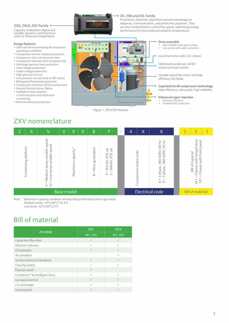
ZX, ZXB and ZXL FamilyProprietary electronic algorithms present advantage on diagnose, communication, and protection purposes. They are also fundamental to control fan speed, optimizing energy performance for local seasonal ambient temperatures
ZXD, ZXLD, ZXV FamilyCapacity modulation digital and variable speed to control precise room or showcase temperature
Good harmonic with 3 AC chokes
Drive assembly• High reliability with good cooling• Easy service with quick connectors
Figure 1. ZXV CDU features
Design features:• With real time monitoring of compressor
operating conditions• Compressor reverse rotation protection• Compressor over current protection• Compressor internal motor protector trip• Discharge gas over heat protection• Over voltage protection• Under voltage protection• High pressure cut out• Low pressure cut out (only on MT series)• Refrigerant flood back protection• Compressor minimum off time protection• Internal thermal sensor failure• Intelligent Store solution: Communication and retail store monitoring•Thermal overload protection
ZXV nomenclature
Bill of material
Z X V 0 9 0 B P - 4 X K 5 5 1
Con
dens
ing
plat
form
V =
Med
ium
tem
p va
riabl
e sp
eed
LV =
Low
tem
p va
riabl
e sp
eed
Max
imum
cap
acit
y*
B =
Nex
t gen
erat
ion
P =
R410
A, P
OE
oil
E =
R404
A, P
OE
oil
Com
pres
sor m
otor
cod
e
K =
3 ph
ase,
380
-420
V, 6
0 H
zD
= 3
pha
se, 3
80-4
20V,
50
Hz
Bill
of m
ater
ial
451
= C
hass
is w
ith
hing
ed d
oor
551
= C
hass
is w
ith
fron
t pan
el
Base model Electrical code Bill of material
ZXV BOMZXV ZXLV
451, 551 451, 551
Liquid line filter drier
Moisture indicator
Oil separator
Accumulator
Suction pressure transducer
Fixed hp switch
Fixed lp switch
CoreSense™ & Intelligent Store
Fan speed control
Circuit breaker
Sound jacket
Optimized condenser coil for maximum heat transfer
Variable speed fan motor and high efficiency fan blade
Copeland Scroll compressor technologyHigh efficiency, ultra quiet, high reliability
Enhanced vapor injection• Improved efficiency• Combined DLT protection
Note: *Maximum capacity condition of evap temp/amb temp/return gas temp Medium temp -10°C/40°C/18.3°C Low temp -32°C/40°C/5°C

6
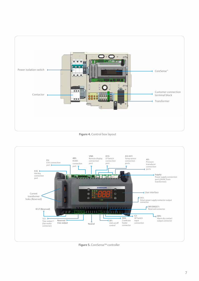
Physical layout of the unitThe following figures give an introduction to the physical layout of the ZXV CDU
Variable speed driver
Capacitor board
EMI Filter board
CoreSense™
Humidity indicator
Choke
Variable speed driver
Oil separator
Liquid receiver
Liquid filter drier
Plate heat exchanger
Suction and liquid service valve
Suction pressure transducer
Compressor oil sight glass
Receiver out service valve
Figure 2. ZXV CDU layout
Figure 3. Drive assembly layout
7
Capacitor board
ContactorCustomer connection terminal block
Transformer
CoreSense™
Figure 5. CoreSense™ controller
Figure 4. Control box layout
H-K:Hot-keyconnectionport
EV:EXV connectionport
485:RS485connectionport
VNR:Remote display connection port
D13:LP Switchconnectionport
A12-A17:Temp sensorconnectionports
Al1:Pressuretransducer connectionports
Supply:Power supply connectionport (24VAC from transformer)
Current transformer
holes (Reserved)
User interface
R-S-T (Reserved)
TO1:Triac output 1 (Fan motorconnecter)
Reserved triac output Neutral
Dl1:Unit on/offcontrol
D04:Crankcaseheaterconnector
C2:HP Switchinputconnection
D03:Driver power supply contactor outputconnector
D01/D02/C1:Reserved connector
D05:Alarm dry contactoutput connector
Power isolation switch
8
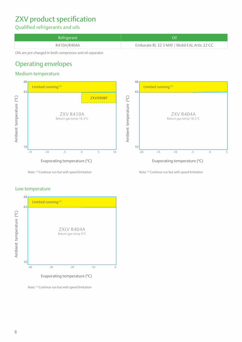
ZXV product specificationQualified refrigerants and oils
Medium temperature
Low temperature
Refrigerant Oil
R410A/R404A Emkarate RL 32 3 MAF / Mobil EAL Artic 22 CC
Oils are pre-charged in both compressor and oil separator.
Operating envelopes
Am
bien
t te
mpe
ratu
re (
0 C)
Am
bien
t te
mpe
ratu
re (
0 C)
Am
bien
t te
mpe
ratu
re (
0 C)
48
43
10
48
43
10
48
43
10
Evaporating temperature (0C)
Evaporating temperature (0C)
Evaporating temperature (0C)
ZXV R410AReturn gas temp 18.3°C
ZXLV R404AReturn gas temp 5°C
ZXV R404AReturn gas temp 18.3°C
Limited running (1)
Limited running (1)
Limited running (1)
-15
-40
-20
Note: (1) Continue run but with speed limitation
Note: (1) Continue run but with speed limitation
Note: (1) Continue run but with speed limitation
-10
-30
-15-5
-20
-100
-10
-510 55
0
0
ZXV090BP
9
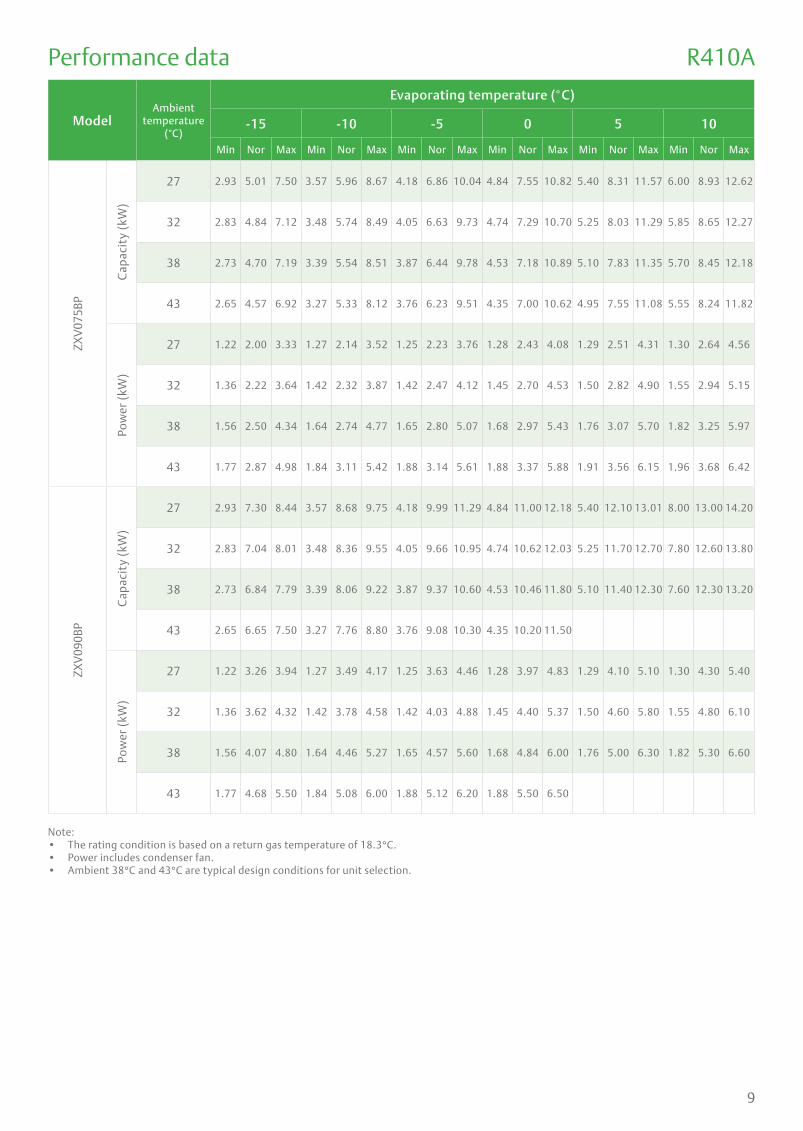
ModelAmbient
temperature (°C)
Evaporating temperature (°C)
-15 -10 -5 0 5 10
Min Nor Max Min Nor Max Min Nor Max Min Nor Max Min Nor Max Min Nor Max
ZXV
075B
P
Cap
acit
y (k
W)
27 2.93 5.01 7.50 3.57 5.96 8.67 4.18 6.86 10.04 4.84 7.55 10.82 5.40 8.31 11.57 6.00 8.93 12.62
32 2.83 4.84 7.12 3.48 5.74 8.49 4.05 6.63 9.73 4.74 7.29 10.70 5.25 8.03 11.29 5.85 8.65 12.27
38 2.73 4.70 7.19 3.39 5.54 8.51 3.87 6.44 9.78 4.53 7.18 10.89 5.10 7.83 11.35 5.70 8.45 12.18
43 2.65 4.57 6.92 3.27 5.33 8.12 3.76 6.23 9.51 4.35 7.00 10.62 4.95 7.55 11.08 5.55 8.24 11.82
Pow
er (
kW)
27 1.22 2.00 3.33 1.27 2.14 3.52 1.25 2.23 3.76 1.28 2.43 4.08 1.29 2.51 4.31 1.30 2.64 4.56
32 1.36 2.22 3.64 1.42 2.32 3.87 1.42 2.47 4.12 1.45 2.70 4.53 1.50 2.82 4.90 1.55 2.94 5.15
38 1.56 2.50 4.34 1.64 2.74 4.77 1.65 2.80 5.07 1.68 2.97 5.43 1.76 3.07 5.70 1.82 3.25 5.97
43 1.77 2.87 4.98 1.84 3.11 5.42 1.88 3.14 5.61 1.88 3.37 5.88 1.91 3.56 6.15 1.96 3.68 6.42
ZXV
090B
P
Cap
acit
y (k
W)
27 2.93 7.30 8.44 3.57 8.68 9.75 4.18 9.99 11.29 4.84 11.00 12.18 5.40 12.10 13.01 8.00 13.00 14.20
32 2.83 7.04 8.01 3.48 8.36 9.55 4.05 9.66 10.95 4.74 10.62 12.03 5.25 11.70 12.70 7.80 12.60 13.80
38 2.73 6.84 7.79 3.39 8.06 9.22 3.87 9.37 10.60 4.53 10.46 11.80 5.10 11.40 12.30 7.60 12.30 13.20
43 2.65 6.65 7.50 3.27 7.76 8.80 3.76 9.08 10.30 4.35 10.20 11.50
Pow
er (
kW)
27 1.22 3.26 3.94 1.27 3.49 4.17 1.25 3.63 4.46 1.28 3.97 4.83 1.29 4.10 5.10 1.30 4.30 5.40
32 1.36 3.62 4.32 1.42 3.78 4.58 1.42 4.03 4.88 1.45 4.40 5.37 1.50 4.60 5.80 1.55 4.80 6.10
38 1.56 4.07 4.80 1.64 4.46 5.27 1.65 4.57 5.60 1.68 4.84 6.00 1.76 5.00 6.30 1.82 5.30 6.60
43 1.77 4.68 5.50 1.84 5.08 6.00 1.88 5.12 6.20 1.88 5.50 6.50
R410A
Note:• The rating condition is based on a return gas temperature of 18.3°C.• Power includes condenser fan.• Ambient 38°C and 43°C are typical design conditions for unit selection.
Performance data
10
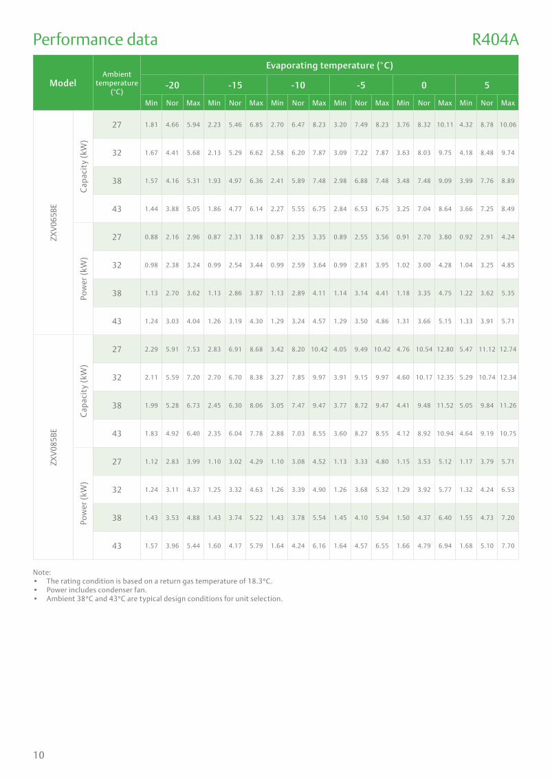
ModelAmbient
temperature (°C)
Evaporating temperature (°C)
-20 -15 -10 -5 0 5
Min Nor Max Min Nor Max Min Nor Max Min Nor Max Min Nor Max Min Nor Max
ZXV
065B
E
Cap
acit
y (k
W)
27 1.81 4.66 5.94 2.23 5.46 6.85 2.70 6.47 8.23 3.20 7.49 8.23 3.76 8.32 10.11 4.32 8.78 10.06
32 1.67 4.41 5.68 2.13 5.29 6.62 2.58 6.20 7.87 3.09 7.22 7.87 3.63 8.03 9.75 4.18 8.48 9.74
38 1.57 4.16 5.31 1.93 4.97 6.36 2.41 5.89 7.48 2.98 6.88 7.48 3.48 7.48 9.09 3.99 7.76 8.89
43 1.44 3.88 5.05 1.86 4.77 6.14 2.27 5.55 6.75 2.84 6.53 6.75 3.25 7.04 8.64 3.66 7.25 8.49
Pow
er (
kW)
27 0.88 2.16 2.96 0.87 2.31 3.18 0.87 2.35 3.35 0.89 2.55 3.56 0.91 2.70 3.80 0.92 2.91 4.24
32 0.98 2.38 3.24 0.99 2.54 3.44 0.99 2.59 3.64 0.99 2.81 3.95 1.02 3.00 4.28 1.04 3.25 4.85
38 1.13 2.70 3.62 1.13 2.86 3.87 1.13 2.89 4.11 1.14 3.14 4.41 1.18 3.35 4.75 1.22 3.62 5.35
43 1.24 3.03 4.04 1.26 3.19 4.30 1.29 3.24 4.57 1.29 3.50 4.86 1.31 3.66 5.15 1.33 3.91 5.71
ZXV
085B
E
Cap
acit
y (k
W)
27 2.29 5.91 7.53 2.83 6.91 8.68 3.42 8.20 10.42 4.05 9.49 10.42 4.76 10.54 12.80 5.47 11.12 12.74
32 2.11 5.59 7.20 2.70 6.70 8.38 3.27 7.85 9.97 3.91 9.15 9.97 4.60 10.17 12.35 5.29 10.74 12.34
38 1.99 5.28 6.73 2.45 6.30 8.06 3.05 7.47 9.47 3.77 8.72 9.47 4.41 9.48 11.52 5.05 9.84 11.26
43 1.83 4.92 6.40 2.35 6.04 7.78 2.88 7.03 8.55 3.60 8.27 8.55 4.12 8.92 10.94 4.64 9.19 10.75
Pow
er (
kW)
27 1.12 2.83 3.99 1.10 3.02 4.29 1.10 3.08 4.52 1.13 3.33 4.80 1.15 3.53 5.12 1.17 3.79 5.71
32 1.24 3.11 4.37 1.25 3.32 4.63 1.26 3.39 4.90 1.26 3.68 5.32 1.29 3.92 5.77 1.32 4.24 6.53
38 1.43 3.53 4.88 1.43 3.74 5.22 1.43 3.78 5.54 1.45 4.10 5.94 1.50 4.37 6.40 1.55 4.73 7.20
43 1.57 3.96 5.44 1.60 4.17 5.79 1.64 4.24 6.16 1.64 4.57 6.55 1.66 4.79 6.94 1.68 5.10 7.70
R404A
Note:• The rating condition is based on a return gas temperature of 18.3°C.• Power includes condenser fan.• Ambient 38°C and 43°C are typical design conditions for unit selection.
Performance data

11
Note:• The rating condition is based on a return gas temperature of 5°C.• Power includes condenser fan.• Ambient 38°C and 43°C are typical design conditions for unit selection.
Model Ambient temp(°C)
Evaporating temperature (°C)
-40 -35 -30 -25 -20 -15 -10 -5 0
Min Nor Max Min Nor Max Min Nor Max Min Nor Max Min Nor Max Min Nor Max Min Nor Max Min Nor Max Min Nor Max
ZXLV
030B
E
Cap
acit
y (k
W)
27 0.79 1.86 2.50 0.94 2.40 3.16 1.21 2.93 3.87 1.45 3.84 5.02 1.75 4.52 5.77 2.17 5.29 6.65 2.62 6.28 7.98 3.10 7.26 9.11 3.65 8.07 9.80
32 0.73 1.82 2.38 0.92 2.30 3.01 1.15 2.86 3.70 1.39 3.69 4.82 1.62 4.28 5.51 2.07 5.13 6.42 2.50 6.01 7.63 2.99 7.00 8.75 3.52 7.78 9.46
38 0.71 1.72 2.27 0.87 2.22 2.89 1.10 2.67 3.61 1.36 3.55 4.63 1.52 4.04 5.15 1.88 4.82 6.17 2.34 5.72 7.25 2.89 6.67 8.37 3.38 7.26 8.82
43 0.66 1.65 2.17 0.84 2.11 2.74 1.06 2.60 3.39 1.29 3.35 4.38 1.40 3.77 4.90 1.80 4.63 5.96 2.21 5.38 6.55 2.76 6.33 7.90 3.16 6.83 8.38
Pow
er (
kW)
27 0.84 1.79 2.33 0.85 1.90 2.46 0.86 2.00 2.33 0.86 2.05 2.40 0.89 2.17 2.98 0.87 2.32 3.20 0.87 2.37 3.37 0.90 2.56 3.58 0.91 2.71 3.82
32 0.94 1.99 2.64 0.95 2.05 2.74 0.95 2.19 2.60 0.95 2.29 2.71 0.98 2.39 3.26 0.99 2.56 3.45 1.00 2.61 3.65 1.00 2.83 3.97 1.02 3.01 4.30
38 1.08 2.28 3.10 1.09 2.36 3.18 1.09 2.53 3.00 1.07 2.59 3.07 1.13 2.71 3.64 1.13 2.88 3.89 1.13 2.91 4.13 1.15 3.16 4.43 1.19 3.36 4.77
43 1.22 2.63 3.54 1.23 2.67 3.66 1.25 2.83 3.36 1.25 2.94 3.48 1.25 3.04 4.06 1.27 3.21 4.32 1.30 3.26 4.59 1.30 3.52 4.89 1.32 3.68 5.18
ZXLV
040B
E
Cap
acit
y (k
W)
27 1.00 2.36 3.17 1.19 3.04 4.00 1.53 3.71 4.90 1.83 4.86 6.36 2.22 5.73 7.30 2.75 6.70 8.42 3.32 7.95 10.11 3.93 9.20 11.54 4.62 10.22 12.42
32 0.92 2.31 3.02 1.16 2.91 3.81 1.46 3.63 4.69 1.76 4.68 6.11 2.05 5.42 6.98 2.62 6.49 8.13 3.17 7.61 9.67 3.79 8.87 11.09 4.46 9.86 11.98
38 0.90 2.18 2.88 1.10 2.82 3.67 1.39 3.38 4.58 1.72 4.50 5.86 1.93 5.12 6.53 2.38 6.11 7.82 2.96 7.24 9.19 3.66 8.45 10.60 4.28 9.20 11.17
43 0.83 2.09 2.75 1.07 2.67 3.47 1.34 3.30 4.30 1.63 4.24 5.55 1.78 4.77 6.21 2.28 5.86 7.55 2.79 6.82 8.29 3.49 8.02 10.01 4.00 8.65 10.61
Pow
er (
kW)
27 1.07 2.34 3.15 1.08 2.48 3.32 1.09 2.62 3.15 1.09 2.67 3.24 1.13 2.84 4.01 1.11 3.03 4.31 1.11 3.09 4.54 1.14 3.35 4.82 1.16 3.54 5.15
32 1.19 2.60 3.56 1.21 2.67 3.70 1.21 2.86 3.51 1.21 2.99 3.65 1.25 3.12 4.39 1.26 3.34 4.65 1.27 3.40 4.92 1.27 3.69 5.35 1.30 3.93 5.80
38 1.37 2.98 4.18 1.39 3.08 4.29 1.38 3.30 4.04 1.36 3.38 4.14 1.44 3.54 4.90 1.44 3.76 5.25 1.44 3.80 5.57 1.46 4.12 5.97 1.51 4.39 6.43
43 1.55 3.44 4.76 1.56 3.49 4.93 1.59 3.69 4.52 1.59 3.84 4.68 1.58 3.97 5.47 1.61 4.19 5.82 1.65 4.26 6.19 1.65 4.59 6.58 1.67 4.81 6.97
Performance data R404A
12
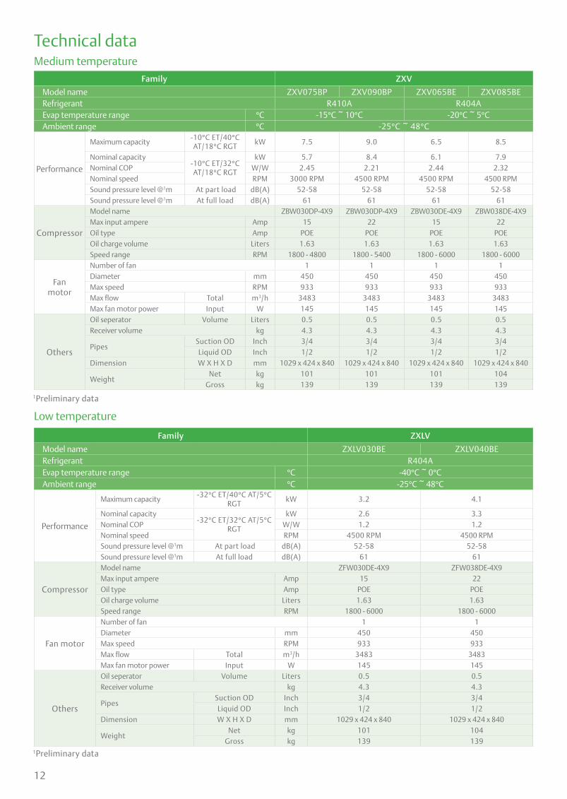
Technical dataMedium temperature
Low temperature
Family ZXV
Model name ZXV075BP ZXV090BP ZXV065BE ZXV085BERefrigerant R410A R404AEvap temperature range °C -15°C ~ 10°C -20°C ~ 5°CAmbient range °C -25°C ~ 48°C
Performance
Maximum capacity-10°C ET/40°C AT/18°C RGT
kW 7.5 9.0 6.5 8.5
Nominal capacity-10°C ET/32°C AT/18°C RGT
kW 5.7 8.4 6.1 7.9Nominal COP W/W 2.45 2.21 2.44 2.32Nominal speed RPM 3000 RPM 4500 RPM 4500 RPM 4500 RPMSound pressure level @1m At part load dB(A) 52-58 52-58 52-58 52-58Sound pressure level @1m At full load dB(A) 61 61 61 61
Compressor
Model name ZBW030DP-4X9 ZBW030DP-4X9 ZBW030DE-4X9 ZBW038DE-4X9Max input ampere Amp 15 22 15 22Oil type Amp POE POE POE POEOil charge volume Liters 1.63 1.63 1.63 1.63Speed range RPM 1800 - 4800 1800 - 5400 1800 - 6000 1800 - 6000
Fanmotor
Number of fan 1 1 1 1Diameter mm 450 450 450 450Max speed RPM 933 933 933 933Max flow Total m3/h 3483 3483 3483 3483Max fan motor power Input W 145 145 145 145
Others
Oil seperator Volume Liters 0.5 0.5 0.5 0.5Receiver volume kg 4.3 4.3 4.3 4.3
PipesSuction OD Inch 3/4 3/4 3/4 3/4Liquid OD Inch 1/2 1/2 1/2 1/2
Dimension W X H X D mm 1029 x 424 x 840 1029 x 424 x 840 1029 x 424 x 840 1029 x 424 x 840
WeightNet kg 101 101 101 104
Gross kg 139 139 139 139
Family ZXLV
Model name ZXLV030BE ZXLV040BERefrigerant R404AEvap temperature range °C -40°C ~ 0°CAmbient range °C -25°C ~ 48°C
Performance
Maximum capacity-32°C ET/40°C AT/5°C
RGTkW 3.2 4.1
Nominal capacity-32°C ET/32°C AT/5°C
RGT
kW 2.6 3.3Nominal COP W/W 1.2 1.2Nominal speed RPM 4500 RPM 4500 RPMSound pressure level @1m At part load dB(A) 52-58 52-58Sound pressure level @1m At full load dB(A) 61 61
Compressor
Model name ZFW030DE-4X9 ZFW038DE-4X9Max input ampere Amp 15 22Oil type Amp POE POEOil charge volume Liters 1.63 1.63Speed range RPM 1800 - 6000 1800 - 6000
Fan motor
Number of fan 1 1Diameter mm 450 450Max speed RPM 933 933Max flow Total m3/h 3483 3483Max fan motor power Input W 145 145
Others
Oil seperator Volume Liters 0.5 0.5Receiver volume kg 4.3 4.3
PipesSuction OD Inch 3/4 3/4Liquid OD Inch 1/2 1/2
Dimension W X H X D mm 1029 x 424 x 840 1029 x 424 x 840
WeightNet kg 101 104
Gross kg 139 139
1Preliminary data
1Preliminary data
13
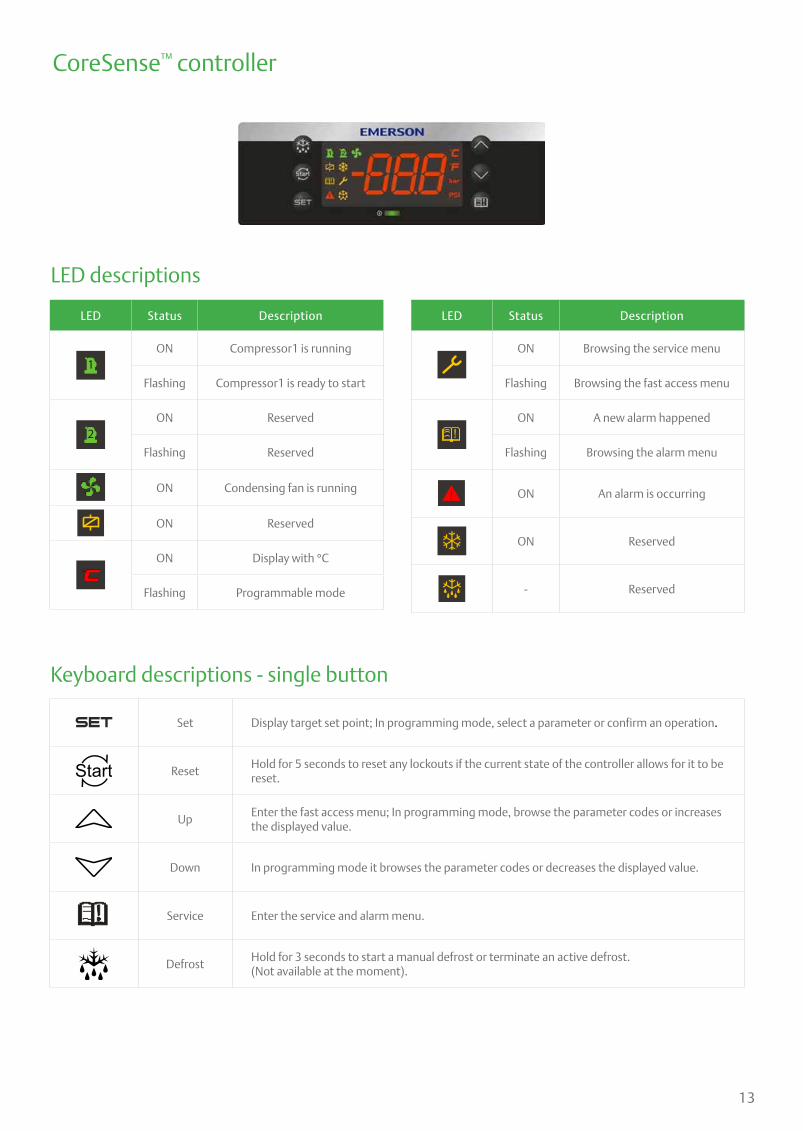
Keyboard descriptions - single button
Set Display target set point; In programming mode, select a parameter or confirm an operation.
Start ResetHold for 5 seconds to reset any lockouts if the current state of the controller allows for it to be reset.
UpEnter the fast access menu; In programming mode, browse the parameter codes or increases the displayed value.
Down In programming mode it browses the parameter codes or decreases the displayed value.
Service Enter the service and alarm menu.
DefrostHold for 3 seconds to start a manual defrost or terminate an active defrost.(Not available at the moment).
LED descriptions
LED Status Description
1ON Compressor1 is running
Flashing Compressor1 is ready to start
2ON Reserved
Flashing Reserved
ON Condensing fan is running
ON Reserved
ON Display with °C
Flashing Programmable mode
LED Status Description
ON Browsing the service menu
Flashing Browsing the fast access menu
!ON A new alarm happened
Flashing Browsing the alarm menu
! ON An alarm is occurring
ON Reserved
- Reserved
CoreSense™ controller
14
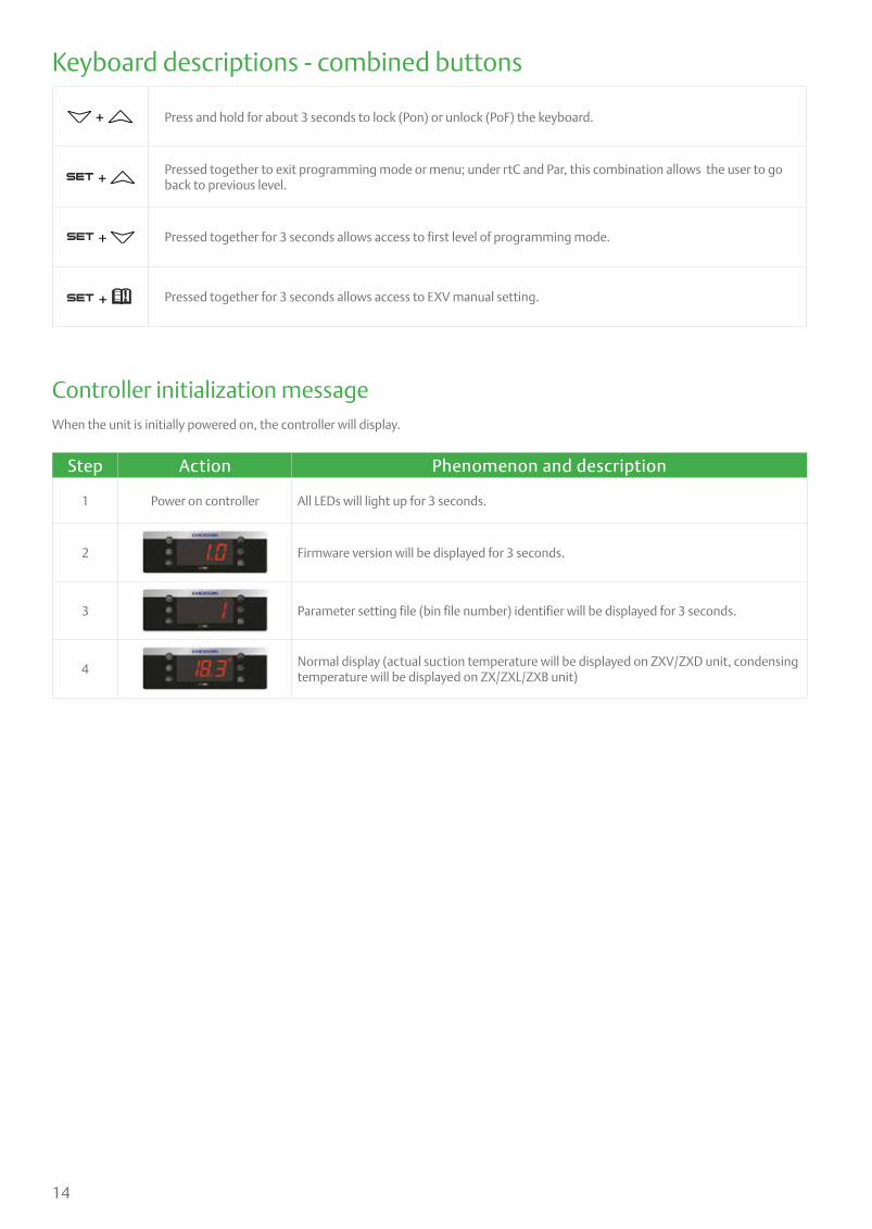
Keyboard descriptions - combined buttons
+ Press and hold for about 3 seconds to lock (Pon) or unlock (PoF) the keyboard.
+ Pressed together to exit programming mode or menu; under rtC and Par, this combination allows the user to go back to previous level.
+ Pressed together for 3 seconds allows access to first level of programming mode.
+ Pressed together for 3 seconds allows access to EXV manual setting.
Controller initialization messageWhen the unit is initially powered on, the controller will display.
Step Action Phenomenon and description
1 Power on controller All LEDs will light up for 3 seconds.
2 Firmware version will be displayed for 3 seconds.
3 Parameter setting file (bin file number) identifier will be displayed for 3 seconds.
4Normal display (actual suction temperature will be displayed on ZXV/ZXD unit, condensing temperature will be displayed on ZX/ZXL/ZXB unit)

15
Bin files number range
Step Action Phenomenon and description
1 Press “ ” + “ ” Enter menu to select “PAr” (parameter) or “rtC”
2 Press “ ” or “ ” Select“PAr (parameter)”
3 Press “ ” Confirm selection
4 Press “ ” or “ ” Browse to parameter C07
5 Press “ ” Confirm selection
6 Press “ ” or “ ” Select refrigerant to be used
7 Press “ ” The number will flash for 3 seconds and confirm the refrigerant selection
8 Press “ ” + “ ” Exit (or exit automatically after waiting for 120 seconds)
Step Action Phenomenon and description
1 Press “ ” + “ ” Enter menu to select “PAr” (parameter) or “rtC”
2 Press “ ” or “ ” Select “rtC”
3 Press “ ”
“n01” , minute
“n02” , hour
“n03” , day
“n04” , month
“n05” , year (last two digits)
4 Press “ ” Display actual value
5 Press “ ” or “ ” Modify the value
6 Press “ ” Press“SET” : the value will flash for 3 seconds, then move to the next value
7 Press “ ” + “ ” Exit to “rtC”
8 Press “ ” + “ ” Exit to main menu (or wait for 120 seconds and exit automatically)
After installation and initial power on, it is critical to double check the parameters below.
Refrigerants
Bin number range Family
701-799 ZXV, ZXLV
850 ZXV service
851 ZXLV service
Step Action Phenomenon and description
1 Press “ ” > 3 secondsPress “ ” button for more than 3 seconds, the measurement units (°C ) will flash together.
2 Press “ ” or “ ” Modify the number for target evaporating temperature
3 Press “ ”Press “ ” to confirm, the number will flash for 2 seconds (or wait for about 10 seconds to confirm)
Evaporating temperature setting
RTC (real time clock) setting

16
Quick access menu browse - sensors status and actual values
Step Action Phenomenon and description
1 Press “ ” Enter quick access menu, will display“P1P”(Press “Up” or “Down” to view other sensors
2 Press “ ” View the actual value of “P1P”
3 Press “ ” Change to next sensor code
4 Press “ ” + “ ” Exit (or exit automatically after waiting for 60 seconds)
Sensor code and values descriptions(“nP”, “noP”, or“nA” mean that the
sensor does not exist; “Err” means that the sensor fails, out of range,
disconnected, or does not configure correctly)
• P1P : Pressure value of suction(Only in ZXD & ZXV)
• P2t : Temperature value of condenser mid coil
• P2P : Pressure value of discharge(not used)
• P3t : Temperature value of DLT(discharge line temperature)
• P4t : Temperature value of VIT(vapor inlet temperature) (only in ZXL, ZXV, ZXB)
• P5t : Temperature value of VOT(vapor outlet temperature) (Only in ZXL, ZXV, ZXB)
• P6t : Temperature value of ambient temperature
• P7t : Not used
• SH : Value of superheat when control logic control vapour injection superheating, or display DLT values when control logic is control DLT
• oPP : Percentage of step EVI valve opening
• LLS : Status of the liquid line solenoid (not used)
• Std : Value of the condenser temperature setting
• Aoo : Percentage of condensing fan driver output
• dSo : Percentage of the PWM output driving the valve of the Digital Scroll compressor (not used)
• inU : Compressor speed percentage of controller sent to driver (only in ZXV)
• inS : Compressor speed percentage of the reading values from driver(only in ZXV)
• iUt : Driver input voltage values(only in ZXV)
• iPr : Driver input power values(only in ZXV)
• Lt : Minimum room temperature(not used)
• Ht : Maximum room temperature(not used)
• tU1 : Voltage 1(R-S terminal) values(not used)
• tU2 : Voltage 2(S-T terminal) values(not used)
• tU3 : Voltage 3(T-R terminal) values(not used)
• tA1 : Current 1(upper transformer) values(not used)
• tA2 : Current 2(lower transformer) values(not used)
• HM : Time Menu(hour & minute)
Pr1 parameter (1st level) browse and modification
Step Action Phenomenon and description
1 Press “ ” + Enter menu to select “PAr” (parameter) or “rtC”
2 Press “ ” or “ ” Select “PAr (parameter)”
3 Press “ ” Confirm, select, and browse Pr1 parameters
4 Press “ ” or “ ” Browse Pr1 parameters
5 Press “ ” View the actual number of the Pr1 parameters
6 Press “ ” or “ ” Modify the actual number of the Pr1 parameters
7 Press “ ”Press“SET” : The number will flash for 3 seconds and confirm the modification; Will go to the next Pr1 parameter
8 Press “ ” + Exit (or exit automatically after waiting for 120 seconds)
17
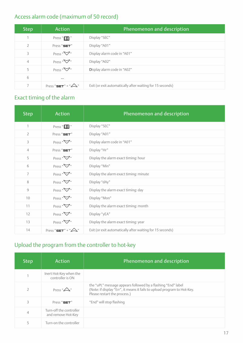
Exact timing of the alarm
Upload the program from the controller to hot-key
Step Action Phenomenon and description
1 Press “ ” Display “SEC”
2 Press “ ” Display “A01”
3 Press “ ” Display alarm code in “A01”
4 Press “ ” Display “Hr”
5 Press “ ” Display the alarm exact timing: hour
6 Press “ ” Display “Min”
7 Press “ ” Display the alarm exact timing: minute
8 Press “ ” Display “dAy”
9 Press “ ” Display the alarm exact timing: day
10 Press “ ” Display “Mon”
11 Press “ ” Display the alarm exact timing: month
12 Press “ ” Display “yEA”
13 Press “ ” Display the alarm exact timing: year
14 Press “ ” + “ ” Exit (or exit automatically after waiting for 15 seconds)
Step Action Phenomenon and description
1Inert Hot-Key when the
controller is ON
2 Press “ ”the “uPL” message appears followed by a flashing “End” label(Note: if display “Err”, it means it fails to upload program to Hot-Key.Please restart the process.)
3 Press “ ” “End” will stop flashing
4Turn-off the controller and remove Hot-Key
5 Turn-on the controller
Access alarm code (maximum of 50 record)
Step Action Phenomenon and description
1 Press “ ” Display “SEC”
2 Press “ ” Display “A01”
3 Press “ ” Display alarm code in “A01”
4 Press “ ” Display “A02”
5 Press “ ” Display alarm code in “A02”
6 …
7 Press “ ” + “ ” Exit (or exit automatically after waiting for 15 seconds)
18
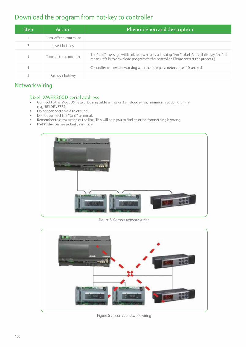
Network wiring
Dixell XWEB300D serial address • Connect to the ModBUS network using cable with 2 or 3 shielded wires, minimum section 0.5mm2
(e.g. BELDEN8772) • Do not connect shield to ground. • Do not connect the “Gnd” terminal. • Remember to draw a map of the line. This will help you to find an error if something is wrong. • RS485 devices are polarity sensitive.
Figure 5. Correct network wiring
Figure 6 . Incorrect network wiring
Download the program from hot-key to controller
Step Action Phenomenon and description
1 Turn-off the controller
2 Insert hot-key
3 Turn-on the controllerThe “doL” message will blink followed a by a flashing “End” label (Note: if display “Err”, it means it fails to download program to the controller. Please restart the process.)
4 Controller will restart working with the new parameters after 10 seconds
5 Remove hot-key

19
ZX CDU connected to XWEB300D
Figure 7. XWEB300D Connected to the Intelligent Store solution module
Dixell XWEB300D configurationXWEB300D is compatible with ZX CDU if XWEB has the library of ZX controller CoreSense.
Login into XWEB• Go to Information → Information• If this is not present, follow the steps below.
Open Dixell website http://www.dixell.com/xweb300d-xweb500-xweb500d/eng/, then login (registration required)• Go to Support → System sw update → XWEB300D XWEB500 XWEB500D• Download the upgrade package with your web-browser, login into XWEB• Go to Information → System Update menu
Provide the XW5 patch file
Once file has been selected wait until the upgrade procedure ends (XWEB reboots)Verify the installation ended successfully by checking into the menu• Go to Information → Information for string
Log in again and set up the ZX CDU
• Go to Configuration → Devices drop-down menu• Go to Actions → New• Enter device name in the Name field (e.g. ZX CDU)• Select “XCM25D” in the Model field• Enter the ModBUS address in the RS 485 address field ∙ Refer to setting of parameter “t01” in pr2 level in CoreSense™ (default setting is “1”)• Click New
Termination resistor for XWEB300D
If XWEB300D is placed at the beginning or at the end of the line, please install its termination resistor by adding a jumper in position 2 (JMP2 on the back side of the unit). Do not add the jumper if XWEB300D is placed in the middle of the RS485 line.
ZX CDU connected to the Dixell XWEB300D with the Intelligent Store solution module using RS485 ModBUS.
Connect the ZX CDU to the ModBUS network as shown in Figure 7. Connect the network cable to the three-terminal connector on the XWEB300D port that has been configured as ModBUS port (COM 12, 13, 14).
Connect port “13” of XWEB300D to port “D0485 +” of CoreSense™ and port “12” of XWEB300D to port “D1485 -” of CoreSense for RS485 communication.

20
Installation
Electrical connectionPower supplyThe ZXV condensing unit electrical connection to the power supply must be made by qualified technicians, who should refer to the electrical diagrams located inside the electric connection panel. The units are designed for below power supply at ± 10% voltage tolerance. The circuit breaker must be switched off before opening the front panel.
Electrical wiringBefore commissioning, ensure that neutral “N” wire is connected to the terminal block (“N” furthest to the right). After proper connection of the ZXV condensing unit, the control LED on the power board and control board will light up. For more details, see wiring diagrams. Customers’ wire size needs to be selected to allow for the maximum operation current of each unit.
Caution! Unit should be powered on at all times except during service. Failure to do so can result in component failure.
Copeland ZX condensing units are delivered with a holding charge of neutral gas. The condensing unit should be located in a place protected from excess amounts of dirt, sand, dust, plastic bags, leaves or paper debris which can cover and block the flow of air over the condenser (fins). The unit must be installed without restricting the airflow. A clogged condenser will result in increased condensing temperature, reducing the cooling capacity, causing the high-pressure switch to trip. Clean the condenser fins on a regular basis.
Condensing unit handling
Transport and storageMove ZXV unit only with appropriate mechanical or handling equipment according to weight. Keep in the upright position. Do not stack single boxes on top of each other without pallet in any case. Keep the packaging dry at all times.

21
Refrigeration piping installationAll interconnecting pipes should be of refrigeration grade, clean, dehydrated and must remain capped at both ends until installation. Even during installation, if the system is left for any reasonable period of time (say two hours), pipes should be re-capped to prevent moisture and contaminants from entering the system.
Do not assume that the service connection sizes on the unit (at the service valves) are the correct size to run your interconnecting refrigeration pipes. The service valve sizes have been selected for convenience of installation and in some cases (larger units) these may be considered too small. However for the very short pipe run within our units, these service connection sizes are adequate. All interconnecting pipes should be sized to satisfy the duty required.
Usually the suction line is insulated, but the liquid line is not. However the liquid line can pick up additional heat from the ambient and adversely affect the sub-cooling desirable for the liquid refrigerant before it enters the expansion valve.
The pipe should be sized to ensure optimum performance and good oil return. The sizing must also take into account the full capacity range through which this particular unit will need to operate.
Pipe runs should be kept as short as possible, using the minimum number of directional changes. Use large radius bends and avoid trapping of oil and refrigerant. This is particularly important for the suction line. The suction line should ideally slope gently towards the unit. Recommendation slope is 1/200~1/250. P traps, double risers and reduced pipe diameters may be required for suction lines where long vertical risers cannot be avoided. All pipes should be adequately supported to prevent sagging which can create oil traps.The recommended pipe clamp support distance is shown in the table.
Liquid line insulationZXV liquid line should be insulated with a 10mm insulation thickness. Temperature could be lower than 0°C.
Brazing recommendationsMaintain a flow of oxygen-free nitrogen through the system at a very low pressure during brazing. Nitrogen displaces the air and prevents the formation of copper oxides in the system. If copper oxidization is allowed to form, the copper oxide material can later be swept through the system and block screens such as those protecting capillary tubes, thermal expansion valves, and accumulator oil return holes. This minimizes any entry of contaminants and moisture.
• Remove the liquid line connection cap.
• Then remove the suction connection cap.
• Open both valves midway. Care should be taken to avoid the holding charge from releasing too quickly.
• Be sure tube fitting inner diameter and tube outer diameter are clean prior to assembly.
• Since both tubes are extended from the condensing unit housing, we recommend insulating the housing by using a wet cloth on the copper tubing.
• Recommended brazing materials: a copper / phosphorous or copper / phosphorous / silver alloy rod should be used for joining copper to copper whereas to join dissimilar or ferric metals, use a silver alloy rod, either flux coated or with a separate.
• Use a double tip torch.
Tube sizeMax distance between
2 clamp support
12.7mm (1/2 inch) 1.20 m
16.0mm (5/8 inch) 1.50 m
22.0mm (7/8 inch) 1.85 m
28.5mm (1 1/8 inch) 2.20 m
End of Tube
During brazing protect housing with damp cloth
During brazing pull back fire insulation
OUTSIDE INSIDE UNIT
22
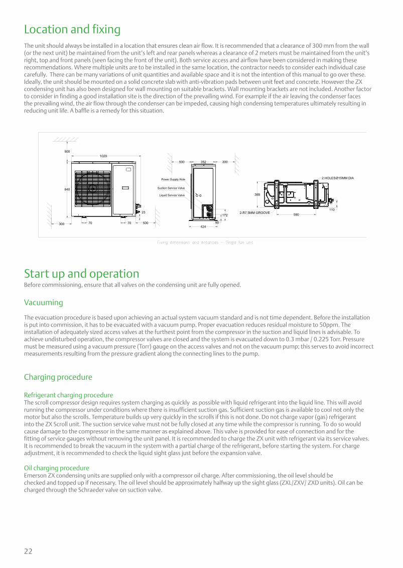
Location and fixing
The unit should always be installed in a location that ensures clean air flow. It is recommended that a clearance of 300 mm from the wall (or the next unit) be maintained from the unit’s left and rear panels whereas a clearance of 2 meters must be maintained from the unit’s right, top and front panels (seen facing the front of the unit). Both service access and airflow have been considered in making these recommendations. Where multiple units are to be installed in the same location, the contractor needs to consider each individual case carefully. There can be many variations of unit quantities and available space and it is not the intention of this manual to go over these. Ideally, the unit should be mounted on a solid concrete slab with anti-vibration pads between unit feet and concrete. However the ZX condensing unit has also been designed for wall mounting on suitable brackets. Wall mounting brackets are not included. Another factor to consider in finding a good installation site is the direction of the prevailing wind. For example if the air leaving the condenser faces the prevailing wind, the air flow through the condenser can be impeded, causing high condensing temperatures ultimately resulting in reducing unit life. A baffle is a remedy for this situation.
840
500
500300
300500 352
7070
23
90
172
424
Power Supply Hole
Suction Service Valve
Liquid Service Valve
1242
172
90
500 300
a 500
500
352
70 70
1029
23
424
94Liquid Service Valve
Suction Service Valve
Power Supply Hole388
110580
2 HOLESØ15MM DIA
2-R7.5MM GROOVE
388
110580
2 HOLESØ15MM DIA
2-R7.5MM GROOVE
1029
Start up and operationBefore commissioning, ensure that all valves on the condensing unit are fully opened.
Vacuuming
The evacuation procedure is based upon achieving an actual system vacuum standard and is not time dependent. Before the installation is put into commission, it has to be evacuated with a vacuum pump. Proper evacuation reduces residual moisture to 50ppm. The installation of adequately sized access valves at the furthest point from the compressor in the suction and liquid lines is advisable. To achieve undisturbed operation, the compressor valves are closed and the system is evacuated down to 0.3 mbar / 0.225 Torr. Pressure must be measured using a vacuum pressure (Torr) gauge on the access valves and not on the vacuum pump; this serves to avoid incorrect measurements resulting from the pressure gradient along the connecting lines to the pump.
Charging procedure
Refrigerant charging procedureThe scroll compressor design requires system charging as quickly as possible with liquid refrigerant into the liquid line. This will avoid running the compressor under conditions where there is insufficient suction gas. Sufficient suction gas is available to cool not only the motor but also the scrolls. Temperature builds up very quickly in the scrolls if this is not done. Do not charge vapor (gas) refrigerant into the ZX Scroll unit. The suction service valve must not be fully closed at any time while the compressor is running. To do so would cause damage to the compressor in the same manner as explained above. This valve is provided for ease of connection and for the fitting of service gauges without removing the unit panel. It is recommended to charge the ZX unit with refrigerant via its service valves. It is recommended to break the vacuum in the system with a partial charge of the refrigerant, before starting the system. For charge adjustment, it is recommended to check the liquid sight glass just before the expansion valve.
Oil charging procedureEmerson ZX condensing units are supplied only with a compressor oil charge. After commissioning, the oil level should bechecked and topped up if necessary. The oil level should be approximately halfway up the sight glass (ZXL/ZXV/ ZXD units). Oil can be charged through the Schraeder valve on suction valve.
23
Scroll compressor rotation directionScroll compressors, like several other types of compressors, will only compress in one rotational direction. Comparing to normal 3-phase fixed compressors, ZXV unit compressor rotational direction is checked at the right direction in the plant. Customer power connection sequence does not change the compressor rotation direction.
Maximum compressor cycleMaximum permitted starts per hour is 10.
Check before starting & during operationBoth valves should be fully opened on the liquid line, in order to prevent trapping liquid. • Check that all valves are fully opened. • After starting and operation conditions are stabilized, it is recommended to check the oil level in compressor(s) and see if there is a need to add oil to ensure a sufficient oil level (halfway up the sight glass).
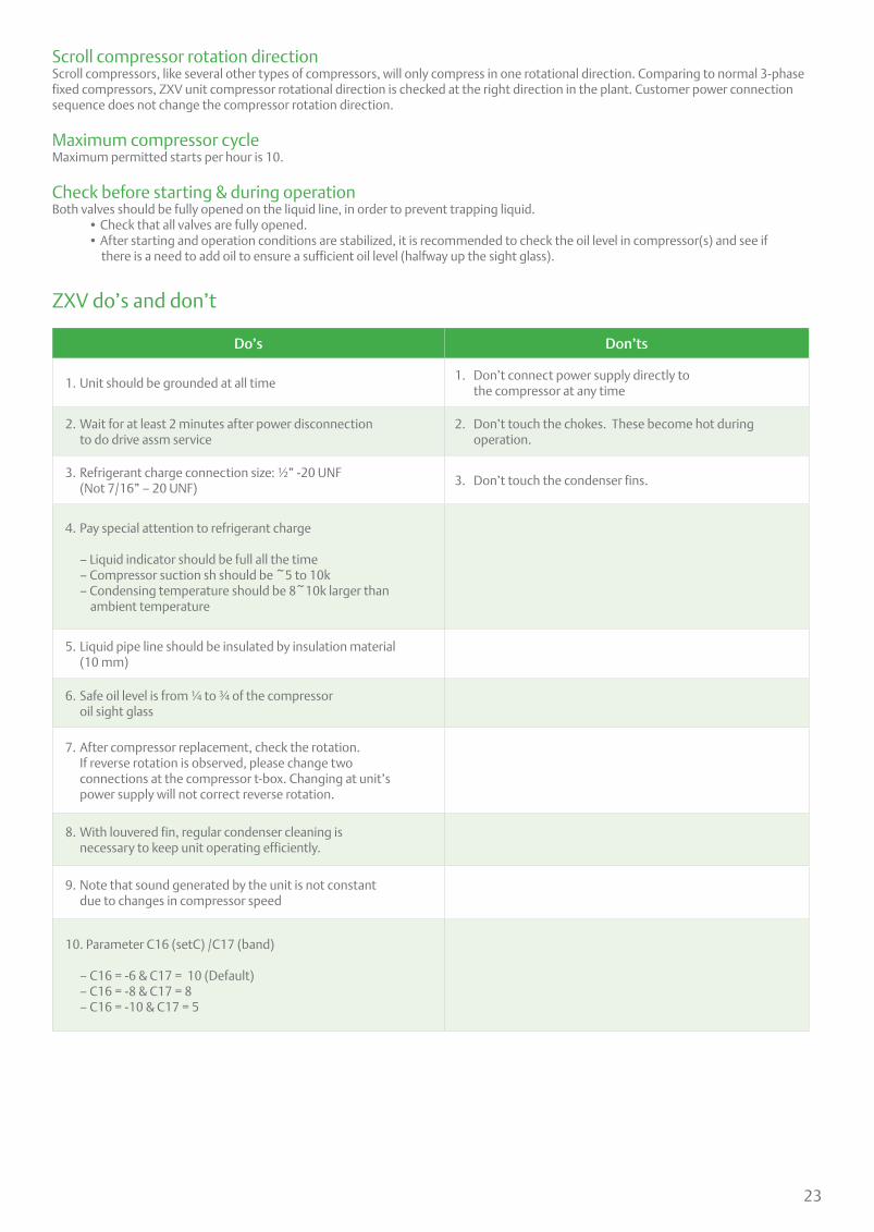
Do’s Don’ts
1. Unit should be grounded at all time1. Don’t connect power supply directly to the compressor at any time
2. Wait for at least 2 minutes after power disconnection to do drive assm service
2. Don’t touch the chokes. These become hot during operation.
3. Refrigerant charge connection size: ½” -20 UNF (Not 7/16” – 20 UNF)
3. Don’t touch the condenser fins.
4. Pay special attention to refrigerant charge
– Liquid indicator should be full all the time – Compressor suction sh should be ~5 to 10k – Condensing temperature should be 8~10k larger than
ambient temperature
5. Liquid pipe line should be insulated by insulation material (10 mm)
6. Safe oil level is from ¼ to ¾ of the compressor oil sight glass
7. After compressor replacement, check the rotation. If reverse rotation is observed, please change two connections at the compressor t-box. Changing at unit’s power supply will not correct reverse rotation.
8. With louvered fin, regular condenser cleaning is necessary to keep unit operating efficiently.
9. Note that sound generated by the unit is not constant due to changes in compressor speed
10. Parameter C16 (setC) /C17 (band)
– C16 = -6 & C17 = 10 (Default) – C16 = -8 & C17 = 8 – C16 = -10 & C17 = 5
ZXV do’s and don’t
24
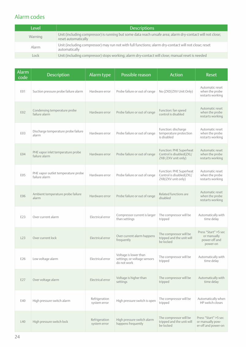
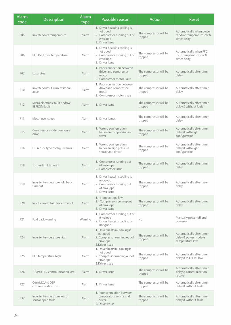
Alarm codes
Alarm code
Description Alarm type Possible reason Action Reset
E01 Suction pressure probe failure alarm Hardware error Probe failure or out of range No (ZXD/ZXV Unit Only)Automatic reset when the probe restarts working
E02Condensing temperature probe failure alarm
Hardware error Probe failure or out of rangeFunction: fan speed control is disabled
Automatic reset when the probe restarts working
E03Discharge temperature probe failure alarm
Hardware error Probe failure or out of rangeFunction: discharge temperature protection is disabled
Automatic reset when the probe restarts working
E04PHE vapor inlet temperature probe failure alarm
Hardware error Probe failure or out of rangeFunction: PHE Superheat Control is disabled(ZXL/ZXB /ZXV unit only)
Automatic reset when the probe restarts working
E05PHE vapor outlet temperature probe failure alarm
Hardware error Probe failure or out of rangeFunction: PHE Superheat Control is disabled(ZXL/ZXB/ZXV unit only)
Automatic reset when the probe restarts working
E06Ambient temperature probe failure alarm
Hardware error Probe failure or out of rangeRelated functions are disabled
Automatic reset when the probe restarts working
E23 Over current alarm Electrical errorCompressor current is larger than settings
The compressor will be tripped
Automatically with time delay
L23 Over current lock Electrical errorOver current alarm happens frequently
The compressor will be tripped and the unit will be locked
Press “Start” >5 sec or manually
power-off and power-on
E26 Low voltage alarm Electrical errorVoltage is lower than settings; or voltage sensors do not work
The compressor will be tripped
Automatically with time delay
E27 Over voltage alarm Electrical errorVoltage is higher than settings
The compressor will be tripped
Automatically with time delay
E40 High pressure switch alarmRefrigeration system error
High pressure switch is openThe compressor will be tripped
Automatically when HP switch closes
L40 High pressure switch lockRefrigeration system error
High pressure switch alarm happens frequently
The compressor will be tripped and the unit will be locked
Press “Start” >5 sec or manually pow-er-off and power-on
Level Descriptions
WarningUnit (including compressor) is running but some data reach unsafe area; alarm dry-contact will not close; reset automatically
AlarmUnit (including compressor) may run not with full functions; alarm dry-contact will not close; resetautomatically
Lock Unit (including compressor) stops working; alarm dry-contact will close; manual reset is needed

25
Alarm code
Description Alarm type Possible reason Action Reset
E41 Low pressure switch alarmRefrigeration system
errorLow pressure switch is open
The compressor will be tripped
Automatically when LP switch closes and time
delay
E44High discharge temperature alarm
Refrigeration system error
Discharge temperature is higher than settings
The compressor will be tripped
Automatically when discharge temperature is lower than settings and
time delay
E46High condensing temperature alarm
Refrigeration system error
Condensing temperature is higher than settings
NoAutomatically when
condensing temperature is lower than settings
E47 EXV Full-open warningRefrigeration system
errorLess refrigerant charge or leakage
NoAutomatically when EXV is
not at full-open
E48 Less injection warningRefrigeration system
errorLess refrigerant charge or leakage
NoAutomatically when PHE super heat is smaller than
settings
E50 High side liquid back warningRefrigeration system
errorSuction liquid back or injection too much
No
Automatically when the difference of discharge
temperature and condensing temperature
is higher than settings and time delay
E80 RTC warning Misc. ErrorThe time is configured for the new controller
NoAutomatically when finish
time configuration
E81 RTF warning Misc. ErrorCommunication error between MCU and unit clock
NoAutomatically when the
communication recovers
E82Probe configuration error alarm
Misc. ErrorThe same probes are configured
NoAutomatically when the probes are configured
correctly
E83Digital inputs configuration error alarm
Misc. ErrorThe same digital inputs are configured
The related functions will be disabled
Automatically when the digital inputs are
configured correctly
E84Compressor configuration error alarm
Misc. ErrorDigital compressor and solenoid valve configura-tion does not match
The compressor will not work
Manually power off and power on after the
compressor configuration is right
E85Injection probe configuration error alarm
Misc. ErrorEXV and injection configuration do not match
EXV will not workAutomatically when injec-tion probe is configured
correctly
L86 EEPROM R/W error lock Misc. Errorwrite/read error into EEPROM
The compressor will tripped and the unit will be locked
Hold “start” button for 5s or manual power off and on, alarm will disappear
when the communication between MCU and EEPROM
is success.
F01 AC input over current Alarm
1. Compressor running out of envelope 2. Input voltage out of range 3. Driver issue
The compressor will be tripped
Automatically after timer delay
F02 DC bus over voltage Alarm
1. Input voltage higher than maximum 2. Compressor running out of envelope
The compressor will be tripped
Automatically when DC bus voltage is smaller than
settings & timer delay
F03 DC bus under voltage Alarm
1. Input voltage lower than minimum2. Compressor running out of envelope
The compressor will be tripped
Automatically when DC bus voltage is higher than
settings & timer delay
26
Alarm code
DescriptionAlarm type
Possible reason Action Reset
F05 Inverter over temperature Alarm
1. Driver heatsink cooling is not good2. Compressor running out of envelope3. Driver issue
The compressor will be tripped
Automatically when power module temperature low & timer delay
F06 PFC IGBT over temperature Alarm
1. Driver heatsink cooling is not good2. Compressor running out of envelope3. Driver issue
The compressor will be tripped
Automatically when PFC IGBT temperature low & timer delay
F07 Lost rotor Alarm
1. Poor connection between driver and compressor motor2. Compressor motor issue
The compressor will be tripped
Automatically after timer delay
F10Inverter output current imbal-ance
Alarm
1. Poor connection between driver and compressor motor2. Compressor motor issue
The compressor will be tripped
Automatically after timer delay
F12Micro electronic fault or drive EEPROM fault
Alarm 1. Driver issueThe compressor will be tripped
Automatically after timer delay & without fault
F13 Motor over speed Alarm 1. Driver issuesThe compressor will be tripped
Automatically after timer delay
F15Compressor model configure error
Alarm1. Wrong configuration between compressor and driver
The compressor will be tripped
Automatically after timer delay & with right configuration
F16 HP sensor type configure error Alarm1. Wrong configuration between high pressure sensor and driver
The compressor will be tripped
Automatically after timer delay & with right configuration
F18 Torque limit timeout Alarm1. Compressor running out of envelope2. Compressor issue
The compressor will be tripped
Automatically after timer delay
F19Inverter temperature fold back timeout
Alarm
1. Driver heatsink cooling is not good2. Compressor running out of envelope3. Driver issue
The compressor will be tripped
Automatically after timer delay
F20 Input current fold back timeout Alarm
1. Input voltage low 2. Compressor running out of envelope 3. Driver issue
The compressor will be tripped
Automatically after timer delay
F21 Fold back warning Warning
1. Compressor running out of envelope2. Driver heatsink cooling is not good
NoManually power-off and power-on
F24 Inverter temperature high Alarm
1. Driver heatsink cooling is not good 2. Compressor running out of envelope3.Driver issue
The compressor will be tripped
Automatically after timer delay & power module temperature low
F25 PFC temperature high Alarm
1. Driver heatsink cooling is not good 2. Compressor running out of envelope3.Driver issue
The compressor will be tripped
Automatically after timer delay & PFC-IGBT low
F26 DSP to PFC communication lost Alarm 1. Driver issueThe compressor will be tripped
Automatically after timer delay & communication recover
F27Com MCU to DSP communication lost
Alarm 1. Driver issueThe compressor will be tripped
Automatically after timer delay & without fault
F32Inverter temperature low or sensor open fault
Alarm
1. Poor connection between temperature sensor and driver2. Driver issue
The compressor will be tripped
Automatically after timer delay & without fault
27
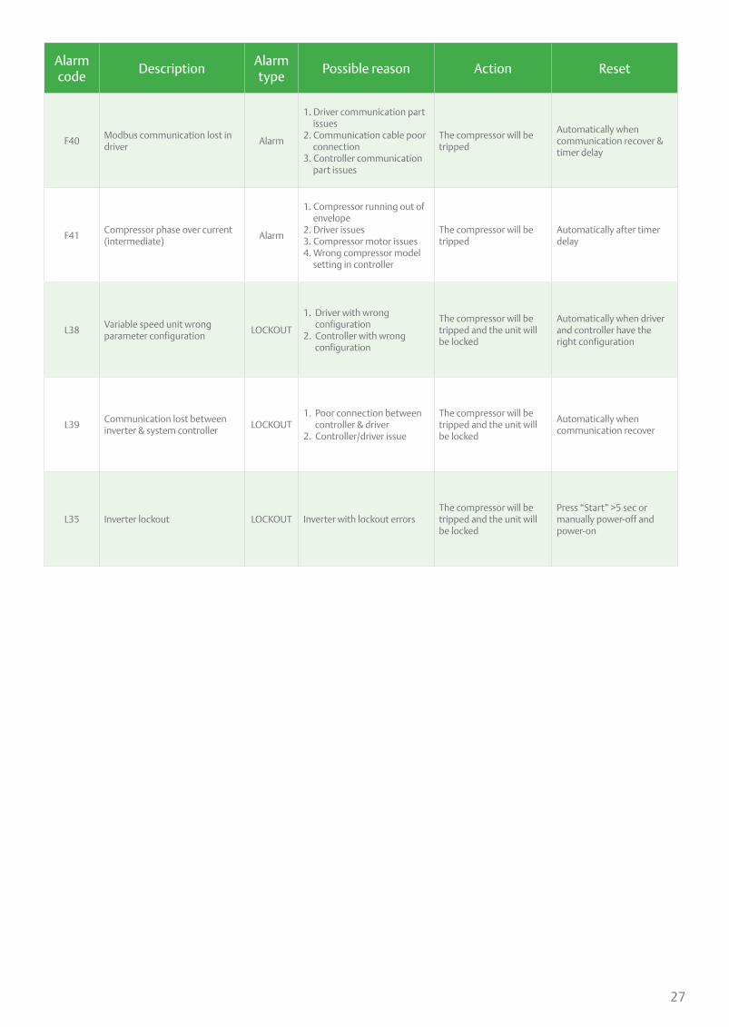
Alarm code
DescriptionAlarm type
Possible reason Action Reset
F40Modbus communication lost in driver
Alarm
1. Driver communication part issues2. Communication cable poor connection3. Controller communication part issues
The compressor will be tripped
Automatically when communication recover & timer delay
F41Compressor phase over current (intermediate)
Alarm
1. Compressor running out of envelope2. Driver issues3. Compressor motor issues4. Wrong compressor model setting in controller
The compressor will be tripped
Automatically after timer delay
L38Variable speed unit wrong parameter configuration
LOCKOUT
1. Driver with wrong configuration 2. Controller with wrong configuration
The compressor will be tripped and the unit will be locked
Automatically when driver and controller have the right configuration
L39Communication lost between inverter & system controller
LOCKOUT1. Poor connection between controller & driver 2. Controller/driver issue
The compressor will be tripped and the unit will be locked
Automatically when communication recover
L35 Inverter lockout LOCKOUT Inverter with lockout errorsThe compressor will be tripped and the unit will be locked
Press “Start” >5 sec or manually power-off and power-on
28
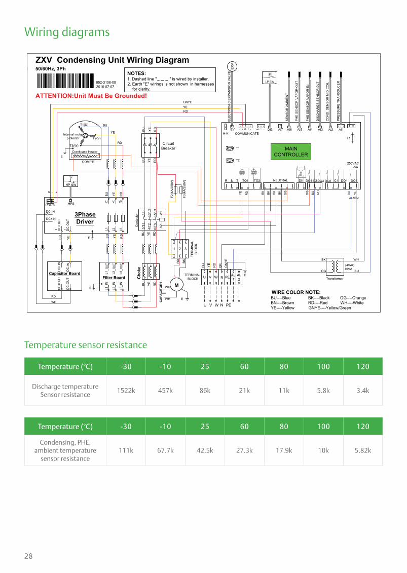
Temperature (°C) -30 -10 25 60 80 100 120
Discharge temperatureSensor resistance
1522k 457k 86k 21k 11k 5.8k 3.4k
Temperature (°C) -30 -10 25 60 80 100 120
Condensing, PHE,ambient temperature
sensor resistance111k 67.7k 42.5k 27.3k 17.9k 10k 5.82k
U V W PE
U V W
24VAC40VA
CA
PAC
ITO
R1
BK
E
M
ZXV Condensing Unit Wiring Diagram380V, 50/60Hz, 3Ph
ATTENTION:Unit Must Be Grounded!
ALARM
CircuitBreaker
PE
BU YE RD
RD
YE RD BK BK BK RD
OG
BK WH
BU
BU
BU YE RD
BK
E
BU YE
BU YE RD
WIRE COLOR NOTE: BU----Blue BK----Black OG----Orange BN----Brown RD----Red WH----White YE----Yellow GNYE----Yellow/Green
NOTES:1. Dashed line " " is wired by installer.2. Earth "E" wirings is not shown in harnesses for clarity.
GN
YE
Transformer
F3(4
A/25
0V)
F2(4
A/25
0V)
N
N
BK
R TO1 TO2 DI1 DO4 C2 DO5DO1C1DO2DO3
T1
T2
H-KEV - + G + -
COMMUNICATEVNR + - DI3 AI7 AI6
SEN
SOR
AM
BIEN
T
AI5
PHE
SEN
SOR
VAP
OR
-OU
T
AI4
PHE
SEN
SOR
VAP
OR
-IN
AI3
DIS
CH
ARG
E SE
NSO
R D
LT
AI2
CO
ND
. SEN
SOR
MID
CO
IL
AI1
F1
SW
P
LP
MAINCONTROLLER
S T NEUTRAL
250VAC /5A
PRES
SUR
E TR
ANSD
UC
ER
1/L1
3/L2
5/L3
A1
2/T1
4/T2
6/T3 A2
L1_ O
UT
L2_O
UT
L3_O
UT
L1_I
N
L2_I
N
L3_I
N
Filter Board
Internal motorprotector
ECOMP'R
T1(U)
T2(V)
T3(W)
BU
Cho
keDC
+IN
DC
- IN
DC
+OU
T
DC
-OU
T
Capacitor Board
L1 L2 L3
U V W
DC-IN
DC+IN
DC
OU
T
DC
OU
T
SW
P
HP
AL1
AL2
BU YE RD
BU YE RD
BU YE RD
BU YE RD
BU YE E
E
TERMINAL BLOCK
RS485
G - +
3PhaseDriver
ELEC
TRO
NIC
EXP
ANSI
ON
VAL
VEEX
V
HPS
1 2 3
Con
tact
or
1 2 Crankcase Heater
OG
OG
+ -
RD
WH
WH
WH
052-3108-00 2016-07-07
GNYEYERD
YE
RD
TER
MIN
ALBL
OC
K
Wiring diagrams
Temperature sensor resistance

29
Notes

30
Notes
General informationTechnical data are correct at the time of printing. Updates may occur, and should you need confirmation of a specific value, please contact Emerson clearly stating the information required.
Emerson cannot be held responsible for errors in capacities, dimensions, etc., stated herein. Products, specifications and data in this literature are subject to change without notice.
The information given herein is based on data and tests which Emerson believes to be reliable and which are in accordance with today’s technical knowledge. It is intended for use by persons having the appropriate technical knowledge and skill, at their own discretion and risk. Our products are designed and adapted for fixed locations. For mobile applications, failures may occur.
The suitability for this has to be assured from the plant manufacturer, which may include making appropriate tests.
Note:The components listed in this catalogue are not released for use with caustic, poisonous or flammable substances. Emerson cannot be held responsible for any damage caused by using these substances.
About Emerson
Emerson (NYSE: EMR), headquartered in St. Louis, Missouri (USA), is a global technology and engineering company providing innovative solutions for customers in industrial, commercial, and residential markets. Our Emerson Automation Solutions business helps process, hybrid, and discrete manufacturers maximize production, protect personnel and the environment while optimizing their energy and operating costs. Our Emerson Commercial and Residential Solutions business helps ensure human comfort and health, protect food quality and safety, advance energy efficiency, and create sustainable infrastructure. For more information visit Emerson.com.

Emerson is a trademark of Emerson Electric Co. or one of its affiliated companies. ©2019 Emerson Electric Co. All rights reserved.
Emerson.com
Contact lists
@EmersonComResAP
Scan to visit:
Emerson Asia
Asia Pacific HeadquartersSuite No. 2503-10A, 25/F, Exchange Tower, 33 Wang Chiu Road, Kowloon Bay, Kowloon, Hong KongTel: (852) 2866 3108Fax: (852) 2520 6227
Australia356 Chisholm RoadAuburn NSW 2144, AustraliaTel: (612) 9795 2800 Fax: (612) 9738 1699
China - BeijingBeijing Sales OfficeRoom 1017 JianWei Building, 66 Nan Lishi Road, XiCheng District, Beijing, PRC Tel: (8610) 5763 0488Fax: (8610) 5763 0499
China - GuangzhouGuangzhou OfficeUnit 2202B, 22/F, Leatop Plaza,32 Zhujiang East Road, Tianhe Dist.,Guangzhou 510623, PRC Tel: (8620) 8595 5188
China - ShanghaiShanghai Sales Office7F, Emerson Building, 1582 GumeiRd, Shanghai, PRCTel: (8621) 3338 7333
India - MumbaiDelphi B-Wing, 601-602, 6th FloorCentral Avenue, Hiranandani Business Park,Powai, Mumbai 400076, IndiaTel: (9122) 6786 0793Fax: (9122) 6662 0500
India - Pune Plot No. 23, Rajiv Gandhi Infotech Park,Phase - II, Hinjewadi,Pune 411 057, Maharashtra, IndiaTel: (9120) 4200 2000Fax: (9120) 4200 2099
IndonesiaBSD Taman Tekno 8 Jl. Tekno Widya Blok H10 No 2 & 3Tangerang Selatan 15314IndonesiaTel: (6221) 2966 6242 Fax: (6221) 2966 6245
JapanShin-yokohama Tosho Building No. 3-9-5 Shin-Yokohama, Kohoku-kuYokohama 222-0033 JapanTel: (8145) 475 6371Fax: (8145) 475 3565
MalaysiaLevel M2, Blk A, Menara PKNS-PJJalan Yong Shook Lin46050 Petaling Jaya, Selangor, Malay-siaTel: (603) 7949 9222Fax: (603) 7949 9333
Middle East & AfricaPO Box 26382Jebel Ali Free Zone - SouthDubai, UAETel: (9714) 811 8100Fax: (9714) 886 5465
Philippines10/F SM Cyber West Avenue, EDSA cor. West Avenue, Barangay Bungad, Diliman, Quezon City 1105 PhilippinesTel: (632) 689 7200
Saudi ArabiaPO Box 34332 - 3620 Building 7874Unit 1, 67th street 2nd Industrial CityDammam, Saudi ArabiaToll Free: 800 844 3426Tel: +966 3 8147560Fax: +966 3 8147570
South Korea3F, The Pinnacle Gangnam 343, Hakdong-ro, Gangnam-gu,Seoul 06060, Republic of KoreaTel: (822) 3483 1500Fax: (822) 592 7883
Taiwan3F No. 122 Lane 235,Pao Chiau Rd., XinDianv Dist.,New Taipei City 23145, Taiwan (R.O.C.)Tel: (8862) 8912 1360Fax: (8862) 8912 1890
Thailand34th Floor, Interlink Tower,1858/133, Bangna Trad,Bangkok 10260, ThailandTel: (662) 716 4700Fax: (662) 751 4241
United Arab EmiratesJebel Ali Free ZonePO Box 26382Dubai UAEToll Free: 800 441 3428Tel: +971 4 811 8100Fax: +971 4 886 5465
VietnamLevel 6, Melinh Point Tower, 2 Ngo Due Ke,District 1, Ho Chi Minh CityVietnamTel: (84) 908 009 189