user manual - farnell element14 · tm tm page 19/05/16 v1.0 front panel overview display...
TRANSCRIPT
www.element14.comwww.farnell.comwww.newark.comwww.cpc.co.ukwww.mcmelectronics.com
TM
TM
Page <1> V1.019/05/16
Digital-Control and Programmable DC Power Supply
Models: 72-2535, 72-2540, 72-2545, 72-2550 & 72-10480
User Manual

www.element14.comwww.farnell.comwww.newark.comwww.cpc.co.ukwww.mcmelectronics.com
TM
TM
Page <2> V1.019/05/16
Safety Symbols This chapter contains important safety instructions that you must follow when operating the Tenma power supply and
when keeping it in storage. Read the following before any operation to insure your safety and to keep the best condition for the Tenma power supply.
Safety Symbols These safety symbols may appear in this manual or on the series.
WARNING
DANGER High Voltage.
Earth (ground) Terminal
Safety Instruction Safety Guidelines Do not block or obstruct the cooling fan vent opening. Avoid severe impacts or rough handling that leads to damage. Do not discharge static electricity. Do not disassemble unless you are qualified as service personnel.
AC Input
AC Input Voltage : 110V / 120V / 220V / 230V , 50 / 60Hz Connect the protective grounding conduct or of the AC power cord to an earth ground, to avoid electrical shock.
Operation Environment Location: Indoor, no direct sunlight, dust free, almost non-conductive pollution (note below) Relative Humidity: < 80% Altitude: < 2000m Temperature: 0-40°C
Storage environment Location: Indoor Relative Humidity: < 70% Temperature: -10-70°C

www.element14.comwww.farnell.comwww.newark.comwww.cpc.co.ukwww.mcmelectronics.com
TM
TM
Page <3> V1.019/05/16
Fuse
Model 110/ 120V 220 /230V
72-10480 T4A/ 250V T2A/ 250V72-2535 T5A/ 250V T3A/ 250V72-2540 T5A/ 250V T3A/ 250V72-2545 T5A/ 250V T3A/ 250V72-2550 T5A/250 T3A/250V
To ensure fire protection, replace the fuse only with the specified type and rating. Disconnect the power cord before fuse replacement. Make sure the cause of fuse blowout is fixed before fuse replacement.
Series Lineup/Main Features Model V Meter A Meter USB Resolution
72-10480 4 digit 4 digit No 10mV/1mA72-2535 4 digit 4 digit Yes 10mV/1mA72-2540 4 digit 4 digit Yes 10mV/1mA72-2545 4 digit 4 digit Yes 10mV/1mA72-2550 4 digit 4 digit Yes 10mV/1mA
Performance Low noise: cooling fan controlled by heat sink temperature Compact size, light weight Operation Constant voltage / constant current operation Digital panel control 4 pairs of panel setup save / recall Coarse and fine Voltage / Current control Software calibration Beep output Key lock function Protection Overload protection Reverse polarity protection Interfaces USB/RS 232 for remote control (only for 72-2535, 72-2540, 72-2545, 72-2550)

www.element14.comwww.farnell.comwww.newark.comwww.cpc.co.ukwww.mcmelectronics.com
TM
TM
Page <4> V1.019/05/16
Front Panel Overview
DisplayVoltage level V Voltmeter displays the setup value of output voltage.
Current level A Displays the setup value of output current.
Condition Indication OVP OVP is the indicator of over voltage protection. When over voltage function is turned on, OVP indicator lights on; when
output voltage is higher than protection setup value due to unexpected conditions, output cuts off and OVP indicator flick-ers; Press the key OVP again, and the power supply recovers.
OCP OCP is OCP indicator. When over current function is turned on, OCP indicator lights on. C.C C.C is constant current indicator. When power supply is in the mode of constant current, this light is on. C.V C.V is constant voltage indicator. When power supply is in the mode of constant voltage, this light is on. OUT OUT is output indicator. If light on, there is voltage output in the output terminal.
Storage Indication
Indication of saving and recalling 5 setups stored internally.

www.element14.comwww.farnell.comwww.newark.comwww.cpc.co.ukwww.mcmelectronics.com
TM
TM
Page <5> V1.019/05/16
Brief Introduction of Panel Operation
Saves or recalls panel settings. For settings, 1 ~ 4 are available. For save / recall details, see Page 08.
Front panel lock_out function. For details, see Page 07
Over-Current protect on/off, Pressing this key for more than 2 seconds will make beep On/OFF.
Over-voltage Protect On/Off
Output On/Off.
Voltage-Current Setting Adjustment
Digit Selector Buttons
Selection Voltage / Current for Adjustment Pressing the key, the volt indicator starts to flicker; pressing it again, the ampere indicator starts to flicker. Then turn the key ADJUST and the settings of the setted voltage or current can be adjusted.
On / Off main power. For power up sequence, see Page 06
Outputs voltage and current.
Connects the ground (earth) terminal.
www.element14.comwww.farnell.comwww.newark.comwww.cpc.co.ukwww.mcmelectronics.com
TM
TM
Page <6> V1.019/05/16
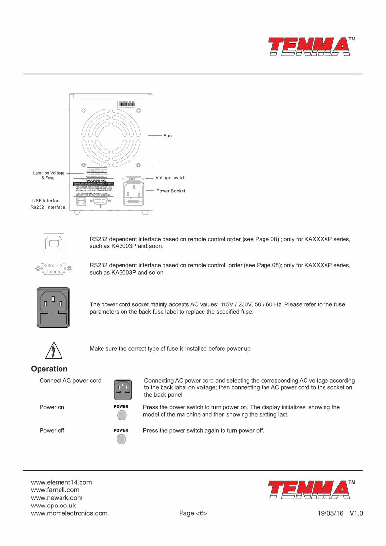
RS232 dependent interface based on remote control order (see Page 08) ; only for KAXXXXP series, such as KA3003P and soon.
RS232 dependent interface based on remote control order (see Page 08); only for KAXXXXP series, such as KA3003P and so on.
The power cord socket mainly accepts AC values: 115V / 230V, 50 / 60 Hz. Please refer to the fuse parameters on the back fuse label to replace the specified fuse.
Make sure the correct type of fuse is installed before power up
Operation Connect AC power cord Connecting AC power cord and selecting the corresponding AC voltage according
to the back label on voltage; then connecting the AC power cord to the socket on the back panel
Power on Press the power switch to turn power on. The display initializes, showing the model of the ma chine and then showing the setting last.
Power off Press the power switch again to turn power off.

www.element14.comwww.farnell.comwww.newark.comwww.cpc.co.ukwww.mcmelectronics.com
TM
TM
Page <7> V1.019/05/16
Output On / OffPanel Operation Press the Output button to turn on output; and the button LED also turns on. Press ing the Output button again to turn off
the output and the LED.
Note: If there are any of the following conditions, the output will automatically turn off. 1. OVP turns on and there are unusual OVP on the output terminal. 2. The setting voltage is more than that of the OVP. 3. Recalling other se tups from the memory.
Beep On / OffPanel Operation By default, the beep sound is enabled. To turn off the beep, press the OCP (BEEP) button for 2 se co nds. A beep comes
out and the beep setting will be turned off . To enable the beep, press the OCP (BEEP) button again for 2 seconds.
Front Panel LockPanel operation Press the LOCK button to lock the front panel button operation. The LED turns on. To unlock, press the LOCK button
for 2 seconds.
Output SetPanel operation 1. Connecting the load to the front port, red ( +), black (-). 2. Setting output voltage and current. Press the button Voltage/Current selection to switch voltage adjustment and current adjustment. Adjusting voltage and
current with Voltage / Current Adjustment knob. By default, the Voltage and Current knob work in the coarse mode. To activate the fine mode, press the buttons to select the coarse mode or the fine mode.
3. Turning on the output and press ing the output button. The button LED turns on and displays CV or CC mode.
Save / Recall SetupSave Setup Back ground The front panel settings can be stored into one of the four internal memories. Contents The following list shows the se tup contents:
Fine / coarse knob editing mode Beep on / off Output voltage / current level The following settings are always saved as “off “. Output on / off Front panel lock on / off
Panel operation Press one of the 4 buttons(M 1,M2,M3,M4) and the LED light turns on accordingly. After you adjust the value, it is saved automatically once it stops blinking.
Recall Set up The front panel settings can be recalled from one of the four internal memories.

www.element14.comwww.farnell.comwww.newark.comwww.cpc.co.ukwww.mcmelectronics.com
TM
TM
Page <8> V1.019/05/16
Press any button of M1 to M4, and take M1 for example; the memory of panel set tings is recalled in M1. After you recall M4, rot at e the shuttle knob and then M5 is recalled.
It means the current memory is recalled that the memory indicator on the panel lights on accordingly.
Note When a set ting is recalled, the out put automatically turns off.
Remote ControlRemote Control Setup All the models 72-2535,72-2540,72-2545,72-2550 etc. can be connected to the PC through interfaces USB/RS232 on the
back of the machine and controlled by the remote control.
COM setting Set up the COM port inside the PC according to the following list. Baud rate: 9600 Parity bit: None Data bit: 8 Stop bit: 1 Data flow control: None
Functionality check Run this query command via the terminal application such as MTTTY (Multi-threaded TTY). *IDN? This should return the identification information: Manufacturer, model name, serial number. 72-10480 SN:xxxxxxxx Vx.xx
Remote Control ProceduresEntering the Remote Control Mode 1. Connecting USB 2. The power supply will automatically connect. After normal connection, there will be a tweet from the power supply itself. 3. The panel keys are locked, so the power supply can only rely on the remote control.Exiting from the Remote Control Mode 1. Closing the remote control software. 2. Disconnecting USB from the back. 3. The power supply disconnects; a tweet from the beep with the hint that the remote control is over. 4. The power supply automatically comes into the panel control mode.

www.element14.comwww.farnell.comwww.newark.comwww.cpc.co.ukwww.mcmelectronics.com
TM
TM
Page <9> V1.019/05/16
FAQ Q1: The panel buttons don’t work when power on. A1: The panel is locked. Press the key for over 2 seconds, and then the panel will unlock.
Q2: Pressing ON/OFF, there is no out put when power on. A2: Current set up is 0.
Q3: Output voltage rises slowly when out put button is on. A3: Current set up is too small.
Q4: Making OCP on and pressing out put switch; and then the out put is automatically shut off. A4: Current protection value set up is too small. You could press output switch and then make OCP on.
SpecificationsNote: The specifications below are tested under the conditions of temperature 25°C ±5°C and the warm-up for 20 minutes.
Models 72-10480 72-2535 72-2540 72-2545 72-2550Voltage Range 0-30V 0-30V 0-30V 0-60V 0-60VCurrent Range 0-3A 0-3A 0-5A 0-2A 0-3A
Load Regulation
Voltage Current ≤0.01% +2mV≤0.1% +5mV
≤0.01% +2mV≤0.1% +10mV
≤0.01% +2mV≤0.1% +5mV
≤0.01% +2mV≤0.1% +5mV
≤0.01% +2mV≤0.1% +5mV
Line Regulation
Voltage Current ≤0.01% +3mV≤0.1% +3mV
≤0.01% +3mV≤0.1% +3mV
≤0.01% +3mV≤0.1% +3mV
≤0.01% +3mV≤0.1% +3mV
≤0.01% +3mV≤0.1% +3mV
Setup Resolution
Voltage Current 10mV1mA
10mV1mA
10mV1mA
10mV1mA
10mV1mA
Setup Accuracy (25°C ±5°C)
Voltage Current ≤0.5% +20mV≤0.5% +5mV
≤0.5% +20mV≤0.5% +5mV
≤0.5% +20mV≤0.5% +10mV
≤0.5% +30mV≤0.5% +5mV
≤0.5% +30mV≤0.5% +5mV
Ripple (20-20M)
Voltage Current ≤1mVrms≤3mArms
≤1mVrms≤3mArms
≤2mVrms≤3mArms
≤1mVrms≤3mArms
≤1mVrms≤3mArms
Temp. Coefficient
Voltage Current ≤150ppm≤150ppm
≤150ppm≤150ppm
≤150ppm≤150ppm
≤150ppm≤150ppm
≤150ppm≤150ppm
Read Back Accuracy
Voltage Current 10mV1mA
10mV1mA
10mV1mA
10mV1mA
10mV1mA
Read Back Temp. Coefficient
Voltage Current ≤150ppm≤150ppm
≤150ppm≤150ppm
≤150ppm≤150ppm
≤150ppm≤150ppm
≤150ppm≤150ppm
Reaction Time
Voltage RiseVoltage Drop
≤100mS≤100mS
(10% Rated Load)
≤100mS≤100mS
(10% Rated Load)
≤100mS≤100mS
(10% Rated Load)
≤100mS≤100mS
(10% Rated Load)
≤100mS≤100mS
(10% Rated Load)

www.element14.comwww.farnell.comwww.newark.comwww.cpc.co.ukwww.mcmelectronics.com
TM
TM
Page <10> V1.019/05/16
Important Notice : This data sheet and its contents (the “Information”) belong to the members of the Premier Farnell group of companies (the “Group”) or are licensed to it. No licence is granted for the use of it other than for information purposes in connection with the products to which it relates. No licence of any intellectual property rights is granted. The Information is subject to change without notice and replaces all data sheets previously supplied. The Information supplied is believed to be accurate but the Group assumes no responsibility for its accuracy or completeness, any error in or omission from it or for any use made of it. Users of this data sheet should check for themselves the Information and the suitability of the products for their purpose and not make any assumptions based on information included or omitted. Liability for loss or damage resulting from any reliance on the Information or use of it (including liability resulting from negligence or where the Group was aware of the possibility of such loss or damage arising) is excluded. This will not operate to limit or restrict the Group’s liability for death or personal injury resulting from its negligence. Tenma is the registered trademark of the Group. © Premier Farnell plc 2012.
InterfaceOptional Interface (for programmable models only): RS232, USBAccessoriesUser manual 1PC; Power Cord: 1×UK power cord and 1×Euro power CordWeight and Dimensions(mm)110(W) × 156(H) × 260(D), 72-10480/722535 × 3.6kg, 72-2540, 72-2545 × 4.3kg, 72-2550 × 4.8kg