user manual for contool 2000xp - home | contronic · 2016-03-22 · 4 starting a project ... 11.1.1...
TRANSCRIPT

User manual for Contool 2000xp Version 2.0.0 (release 3058)
© 2011-08-23, Conson A/S, all rights reserved.
Copying all or part of this manual is only allowed by written permission from Conson A/S.
Short excerpts for use in education or press statement are allowed by stating the source
reference.
Guidelines on how to work with Contool 2000xp, especially from a technical point of view

Content
1 INTRODUCTION ...................................................................................................................... 1.1
2 QUICK START GUIDE ............................................................................................................ 2.1
2.1 BEST PRACTICE SHORT LIST ................................................................................................ 2.1
3 INSTALLATION ....................................................................................................................... 3.1
3.1 PROJECT FILES ................................................................................................................... 3.1
4 STARTING A PROJECT ......................................................................................................... 4.1
4.1 STARTING WITH AN EMPTY PROJECT .................................................................................... 4.1
4.2 IMPORTING A PROJECT FROM A PREVIOUS VERSION .............................................................. 4.2
4.2.1 Exporting files ............................................................................................................... 4.2
4.2.2 Importing files ............................................................................................................... 4.2
4.3 DOWNLOADING DATA FROM MODULES .................................................................................. 4.2
4.4 CHANGING LICENCE ............................................................................................................ 4.3
5 OVERALL ORGANIZATION OF THE USER INTERFACE .................................................... 5.1
6 DETECTION OF MODULES AND XP SENSORS .................................................................. 6.2
6.1 PLACING DETECTED MODULES ............................................................................................. 6.2
6.2 PLACING DETECTED XP SENSORS ....................................................................................... 6.2
7 FLOOR PLAN: DESIGN STATE ............................................................................................. 7.1
7.1 THE MAIN PANEL ................................................................................................................. 7.1
7.1.1 Drag and drop .............................................................................................................. 7.1
7.1.2 Hovering ....................................................................................................................... 7.1
7.1.3 Left-clicking .................................................................................................................. 7.1
7.1.4 Right-clicking ................................................................................................................ 7.1
7.1.5 Drawing lines ................................................................................................................ 7.2
7.2 THE ACTION PANEL ............................................................................................................. 7.2
7.2.1 Floor plans .................................................................................................................... 7.2
7.2.2 Floor plan links ............................................................................................................. 7.4
7.2.3 Sensors/actors ............................................................................................................. 7.5
7.2.4 Detect XP sensors........................................................................................................ 7.5
8 FLOOR PLAN: PROGRAMMING STATE .............................................................................. 8.1
8.1 THE MAIN PANEL ................................................................................................................. 8.1
8.1.1 Hovering ....................................................................................................................... 8.1
8.1.2 Left-clicking .................................................................................................................. 8.1
8.1.3 Right-clicking ................................................................................................................ 8.1
8.1.4 Right-click menu: Actor console… ............................................................................... 8.2
8.1.5 Right-click menu: Actor programming… ...................................................................... 8.2
8.1.6 Right-click menu: Setup alert… .................................................................................... 8.2
8.1.7 Right-click menu: Configure webcam… ....................................................................... 8.3
8.1.8 Right-click menu: Configure… ..................................................................................... 8.3
8.1.9 Right-click menu: Connect eye… ................................................................................. 8.3
8.1.10 Right-click menu: Upload single module… .............................................................. 8.4
8.2 THE ACTION PANEL ............................................................................................................. 8.4
8.2.1 General workflow.......................................................................................................... 8.4
8.2.2 Alternative workflow: Programming multiple push panels at the same time ................ 8.5
8.2.3 Alternative workflow: Programming remotes through eyes ......................................... 8.6
8.2.4 Alternative workflow: Programming by selecting module and channel ........................ 8.6

8.2.5 Alternative workflow: Custom programming of all on/all off ......................................... 8.6
8.3 THE PROGRAMMING DIALOG ................................................................................................ 8.7
8.3.1 The settings section ..................................................................................................... 8.7
8.3.2 The programming section ............................................................................................ 8.7
8.4 THE SENSORS .................................................................................................................... 8.8
8.4.1 XP sensor ..................................................................................................................... 8.8
8.4.2 XP28 ............................................................................................................................. 8.8
8.4.3 B&O .............................................................................................................................. 8.8
8.4.4 UHF .............................................................................................................................. 8.9
8.4.5 IR .................................................................................................................................. 8.9
8.4.6 Timer ............................................................................................................................ 8.9
8.4.7 CP programming (XP20) .............................................................................................. 8.9
9 FLOOR PLAN: USAGE STATE .............................................................................................. 9.1
9.1 THE MAIN PANEL ................................................................................................................. 9.1
9.1.1 Left-clicking .................................................................................................................. 9.1
9.1.2 Double-clicking ............................................................................................................. 9.1
9.1.3 Actor feedback ............................................................................................................. 9.1
9.2 THE ACTION PANEL ............................................................................................................. 9.1
9.2.1 Miscellaneous ............................................................................................................... 9.1
9.2.2 Sensor .......................................................................................................................... 9.3
10 FLOOR PLAN: THE SETTINGS MENU ................................................................................ 10.1
10.1.1 Invert function ......................................................................................................... 10.1
10.1.2 Automatic connection ............................................................................................. 10.1
10.1.3 Show connection lines ........................................................................................... 10.1
10.1.4 Show info panels .................................................................................................... 10.1
10.1.5 Fire on select in programming state ....................................................................... 10.2
10.1.6 Fire on select in usage state .................................................................................. 10.2
11 PROGRAMMING EXAMPLES FOR THE XP SERIES ......................................................... 11.1
11.1 EXHAUST FAN ................................................................................................................... 11.1
11.1.1 Auto Report Events ................................................................................................ 11.1
11.1.2 Actor Programming ................................................................................................ 11.1
11.1.3 Invert function ......................................................................................................... 11.1
11.1.4 A note on the Fan symbol and XP24/XP24P ......................................................... 11.2
11.2 CURTAIN CONTROL ........................................................................................................... 11.2
11.2.1 Curtain actors ......................................................................................................... 11.2
11.2.2 Programming Curtains ........................................................................................... 11.2
11.2.3 All on/All off functions with curtains ........................................................................ 11.3
11.2.4 Direct programming ................................................................................................ 11.4
11.2.5 Controlling blinds .................................................................................................... 11.4
11.3 B&O ................................................................................................................................ 11.4
11.3.1 Programming in Contool 2000xp ............................................................................ 11.4
11.3.2 Operating the real-life BEO4 remote control .......................................................... 11.5
11.3.3 Programming example ........................................................................................... 11.6
11.4 PROGRAMMING WITH HELP FUNCTION, GROUP ON/OFF AND SHORT/LONG ............................. 11.6
11.4.1 Fundamentals of group on/off ................................................................................ 11.7
11.4.2 Fundamentals of short/long .................................................................................... 11.7
11.4.3 Fundamentals of invert ........................................................................................... 11.8
12 FUSE BOX ............................................................................................................................. 12.1
12.1 MOVING MODULES AROUND ............................................................................................... 12.1

12.1.1 Identifying a CP module ......................................................................................... 12.1
12.1.2 Identifying an XP module ....................................................................................... 12.1
12.1.3 Moving a module .................................................................................................... 12.1
12.1.4 Replacing a broken module ................................................................................... 12.2
12.2 UPLOADING DATA TO MODULES ......................................................................................... 12.2
12.2.1 Installing and detecting the Conbeam (XP78) ....................................................... 12.2
12.2.2 Selecting data to upload ......................................................................................... 12.3
12.2.3 Uploading data (XP130 and XP78) ........................................................................ 12.4
12.2.4 Uploading data (XP78) ........................................................................................... 12.5
12.3 DOWNLOADING DATA FROM MODULES ................................................................................ 12.5
12.3.1 The tree download mode ....................................................................................... 12.7
12.3.2 The CP interval mode ............................................................................................ 12.7
12.3.3 The CP anonymous mode ..................................................................................... 12.7
12.3.4 Downloading data (XP130) .................................................................................... 12.7
12.3.5 Downloading data (XP78) with wizard ................................................................... 12.8
13 QUOTATION .......................................................................................................................... 13.1
13.1 QUOTATION (AND TEMPLATE) ............................................................................................ 13.1
13.2 UNIT LIST ......................................................................................................................... 13.2
13.2.1 Discount ................................................................................................................. 13.2
13.2.2 Price lists ................................................................................................................ 13.2
13.2.3 Adding and removing units to the quotation ........................................................... 13.3
13.2.4 Managing units ....................................................................................................... 13.3
13.3 INVOICE ........................................................................................................................... 13.4
14 DOCUMENTATION ............................................................................................................... 14.1
14.1 FLOOR PLAN REPORT ........................................................................................................ 14.1
14.2 FUSE BOX REPORT ........................................................................................................... 14.1
14.3 SENSOR REPORT .............................................................................................................. 14.1
14.4 ACTOR REPORT ................................................................................................................ 14.1
14.5 FUNCTION COLLECTION REPORT ........................................................................................ 14.1
15 TIMERS .................................................................................................................................. 15.1
15.1 TIMER DESCRIPTION ......................................................................................................... 15.1
15.2 TIMER ACTION AND TIME TRIGGER ...................................................................................... 15.1
15.3 REPEAT ........................................................................................................................... 15.1
15.4 TIMER REPETITION SETTINGS............................................................................................. 15.2
16 WEB SERVICE ...................................................................................................................... 16.1
16.1 SETTING UP THE WEB SERVICE ......................................................................................... 16.1
16.1.1 External access ...................................................................................................... 16.1
16.1.2 Wap setup .............................................................................................................. 16.2
16.1.3 Html setup .............................................................................................................. 16.2

2011-08-23 section 1.1
1 Introduction Contool 2000xp is the successor of the old Contool application which was used to
programme modules in the original CP series.
The new Contool 2000xp is an application offering the complete set of tools needed to
work with the new Concept 2000xp – also referred to as the XP series. Conson is
renowned for its backwards compatibility and this quality persists in Contool 2000xp since
it also fully supports the original CP series.
In short Contool 2000xp supports the complete process when working with a new
installation: projecting an installation with the end user, making a quotation, programming
and documenting an installation is all integrated in the intuitive workflow.
Even though this user manual focuses on the use of Contool 2000xp from a technical
point of view, it is extremely important to point out that the purpose of Contool 2000xp is to
make a piece of software which is easy to use for non-technicians. The end user is in
focus due to the fact that it all adds up to provide a user-friendly view of the installation on
a blueprint which can be directly operated by the end user.
Even though Contool2000xp is now released in version 1.0, we will continuously be
adding more features and will appreciate any feedback you may have. We cannot
guarantee that your feedback will be handled right away but we do guarantee that all
remarks will be recorded and taken into consideration.

2011-08-23 section 2.1
2 Quick start guide We strongly advise you to read the complete manual carefully before creating your first
project, but we also realize that sometimes time is short. Consequently, we have summed
up the most important key points in a quick start guide.
When planning an installation, it is advisable to assign a fuse for each XP11 and perhaps
even an HPFI relay if it is economically feasible.
The default IP address is 192.168.1.17 when connecting to the XP130. Best practice is to
use a notebook with a wireless connection enabling you to move freely around the
installation with Contool 2000xp at hand. All XP modules and XP sensor will be
automatically detected when connecting to XP130 (in online mode). The modules will be
placed on the fuse box tab in a random order, while the XP sensor will be listed on the
floor plan tab (on the inline tab “Detect XP sensors” in “Design state”).
Verify that the number of XP modules and XP sensors match the expected number in the
installation. If this is the case you can assume that all modules and sensors are wired up
correctly since they all respond. If the numbers do not match try to manually detect them
as described in section 6. If you are still missing modules and/or sensors, you should start
to verify that you have connected everything correctly.
The XP sensors must be dragged to the floor plan before they become operational in
Contool 2000xp. Upload a blueprint image or similar to the floor plan to make the most
intuitive installation.
Before placing the XP sensors, you need to activate each sensor by pressing the two
upper buttons – see section 7.2.4. Doing so will also timestamp the detected XP sensors
in Contool 2000xp and by keeping track of your route through the installation, you will
know in which order to place the sensors. By bringing a wireless connected notebook, you
will be able to easily verify, that all sensors are being time stamped correctly – and thus
avoiding to accidently place them in an incorrect order at the floor plan.
2.1 Best practice short list
Read the manual before you run into an accident
Make sure you have lights available at your installation
Your toolbox should contain: work light, wireless router (tested before you leave for
the work site), an XP130, and a small working test project
Bring enough working sockets (with cord and light bulb) to enable you to have a
light connected to all outlets you will be programming
A handy tool is to further bring a module and a switch that you are confident is
working for testing purposes. Mount the switch at your XP24 at clamp B-C-D-E to

2011-08-23 section 2.2
make the switch run on its own “Consonbus”1. Mount the module at the “Conbus”2
as the last module on the “Conbus”.
When programming a module it will power down and reboot. So make sure to
programme in accordance to the end users’ needs. And remember that it is
possible to programme a module at a time if you need to.
All switches have unique serials which cannot be overwritten
When testing a module directly on the claps (minus to a clap) make sure to tighten
the screw on the clap. Otherwise you might end up with a loose connection.
When programming or firmware updating a module or sensor/switch all data in the
module is overwritten.
Save your project regularly using the save as… functionality and provide a new
name each time (like “my project 1 – units placed” and “my project 2 – XP24
programmed”). This will enable you to go back in time to any critical point in your
installation.
Even though all naming is stored in the project – and backed up in the XP modules
and sensors (with a few limitations) for restoring a project – it is still important to
document the installation properly.
1 The ”long” bus
2 The “short” bus
3 XP25xx is shown to the left, and XP26xx is shown to the right
2 The “short” bus

2011-08-23 section 3.1
3 Installation Contool 2000xp is distributed as a single installation file which currently runs on Windows
(XP, Vista and Windows 7) in both 32-bit and 64-bit.
The installation is done through a classic installation wizard:
1. Accept the license agreement to proceed.
2. Select destination directory. Default is ““Program Files\Contool2000XP”.
3. Select whether to create a Start Menu folder/shortcut. Default is “Contool2000XP”.
4. Close installation wizard.
Finally the application can be uninstalled both through the Start Menu folder as well as
Programs under Control Panel.
3.1 Project files
All projects in Contool 2000xp have a unique name which makes it easy to identify a
project and which is also used to organize the project files. Creating a new project in
Contool also creates a new folder located at [installation directory]\Projects\[project
name]\.
This is useful when moving the application from one computer to another: simply copy the
complete project folder. Make sure that the revision number of the destination installation
of Contool 2000xp is identical with the source installation. This can be verified by looking
at the installation directory – or in the “Help” menu, “About” dialog.

2011-08-23 section 4.1
4 Starting a project Start Contool 2000xp from the Start menu, Contool2000xp folder by clicking the .exe file
named “Contool2000XP” with the symbol.
This brings up the login screen with a list of projects to the left. Initially, this list will be
empty but when it is populated, selecting a project to the left will display detailed
information in the fields to the right.
4.1 Starting with an empty project
Start by pressing the “Create new…” button, which will bring up the “Create new” dialog:
The top of the dialog holds the option of whether to create a new project or import an
existing project. This section describes the default option (creating a new project).
The field “Project name” is mandatory while remaining fields are not mandatory. If you
choose to fill out the user name and password, you will be prompted to login before being
able to start the project.
The most important fields are the IP and port of the XP130 which you will be connecting
through, and the checkbox indicating whether to start in offline mode.
When starting a project, Contool will even in offline mode try to start its web service by
binding it to port 9090. Due to the fact that only one service can be bound to a port, an
error message will occur if trying to start a project in more than one instance of Contool.
The second started project will work just fine – only the web service will not be
operational.
Finally an XP130 only accepts one open connection, so it is only possible to have one
project in online mode accessing the same XP130.

2011-08-23 section 4.2
4.2 Importing a project from a previous version
Saving and loading a project in Contool is dependent on the Contool release number.
Consequently, you cannot load a project file from a previous version of Contool. If you
need to upgrade a project to a newer version of Contool use the “Export Project to files…”
and “Import existing Project…”
4.2.1 Exporting files
To export a project, choose “Files”, “Export Project to
files”. This will open a file dialog, where you can point to
an existing folder where your export files should go – or
a new folder can be created directly from the file dialog.
Either way a new folder with the project name will be
created at the selected location. If such a folder is
already present at the selected location, the export will
not be executed in order to ensure that previous export
are not accidently overwritten.
After the export, the folder is populated with a .con file
for each module in the system, a floor plan table (.ftp)
and the graphic files for each floor plan.
If you want to exchange projects with others, you can zip the entire folder.
4.2.2 Importing files
To import the project in another version of
Contool, choose the second option in top of the
“Create new…” dialog marked in red.
After having filled out all relevant fields in the
dialog, pressing OK will bring up a file chooser
dialog. Browse to your folder containing the
exported project files in order to have Contool
import the project. After a while you should get
the “Project import successful” dialog. Note that
importing big projects may take a couple of
minutes to complete. Now you can save your
project as a normal Contool project.
The import function can only be executed in
offline mode. To go online with the system after
successful import, choose “Files”, “Disconnect”,
uncheck the “Offline mode” checkbox in the
project view, and start the project again.
4.3 Downloading data from modules
If you lose a project file it is still possible to recreate a project from data in the
modules/sensors by downloading data from the modules.

2011-08-23 section 4.3
The new units from Concept 2000xp contain enough data to automatically restore a
project, while the old units from Concept 2000 only contain the most critical data. A wizard
is provided when downloading data from the old modules in order to guide the user to fill
in the missing pieces.
The process is described in detail in 12.3.
4.4 Changing licence
When starting Contool for the first time all functionality will be present. But it is possible to
restrict this functionality to the suit the needs of a typical “end user”. This is done in the
Settings menu by clicking the “Change licence…” menu item.
Doing so will display a dialog requesting a global password needed to switch to the limited
end user licence. In order to switch back to the full licence, use the same menu item – and
the same global password. This password is available on request.
Notice that the license setting affects the installation of Contool and not the project. In
other words the complete Contool installation will have its licence changed but it will still
be possible to move a project to another (full) installation and thus have full functionality in
that (and any other) project.

2011-08-23 section 5.1
5 Overall organization of the user interface When the project is loaded the below user interface is shown. The interface has the same
basic look and feel throughout the entire application:
At the top a menu is located
o Files gives access to functionality like save, export, import and close
o Settings will be described in detail where they apply
o Help contains a link to documentation etc.
At the left (marked in red) a series of tabs are located which contains the main
panel of Contool 2000xp
o Floor plans holds blueprints and placed units
o Fuse box holds fuse boxes and upload/download functionality
o Graphs display data from the modules. Beta version
o Quotations contains prices, unit lists and a simple invoice system
o Documentation automatically created from data in floor plans and fuse
box.
o Timers provides functionality to trigger actions based on setup rules
o Web service gives access to setup web-access to Contool2000xp
At the right (marked in green) an action panel associated with the selected tab
from the right side is located. Not all tabs have an action panel.

2011-08-23 section 6.2
6 Detection of modules and XP sensors There are three (identical) ways that Contool 2000xp can detect modules and XP sensors:
1. By simply starting the application in online mode (by not checking the “offline
mode” checkbox at the start up screen)
2. By navigating to the fuse box tab and selecting “Detect XP” in the panel to the left
3. By navigating to the floor plans tab and selecting “Detect XP” in the panel to the
left
If starting the application in online mode, all modules and sensors will be detected during
start up, but it is also possible to detect newly added units after the project is loaded.
6.1 Placing detected modules
All detected modules will automatically be added to the fuse box at the first vacant slot
from the top left corner. Since the modules will respond in a random order during
detection, they must manually be replaced afterwards. See 12.1 for further detail.
6.2 Placing detected XP sensors
Unlike the modules, the detected XP sensors are not automatically placed. Instead they
are listed in floor plan in design state in the “Detect XP sensors” tab. See 7.2.4 for further
detail.
2011-08-23 section 7.1
7 Floor plan: Design state The floor plan tab is the most comprehensive part of Contool 2000xp. The action panel
consists of three inline tabs.
Design state
Programming state
Usage state
Together they form a workflow for setting up an installation. The first part of this workflow
is the design state used to add all needed units and connect these. Consequently, the
target audience is technicians.
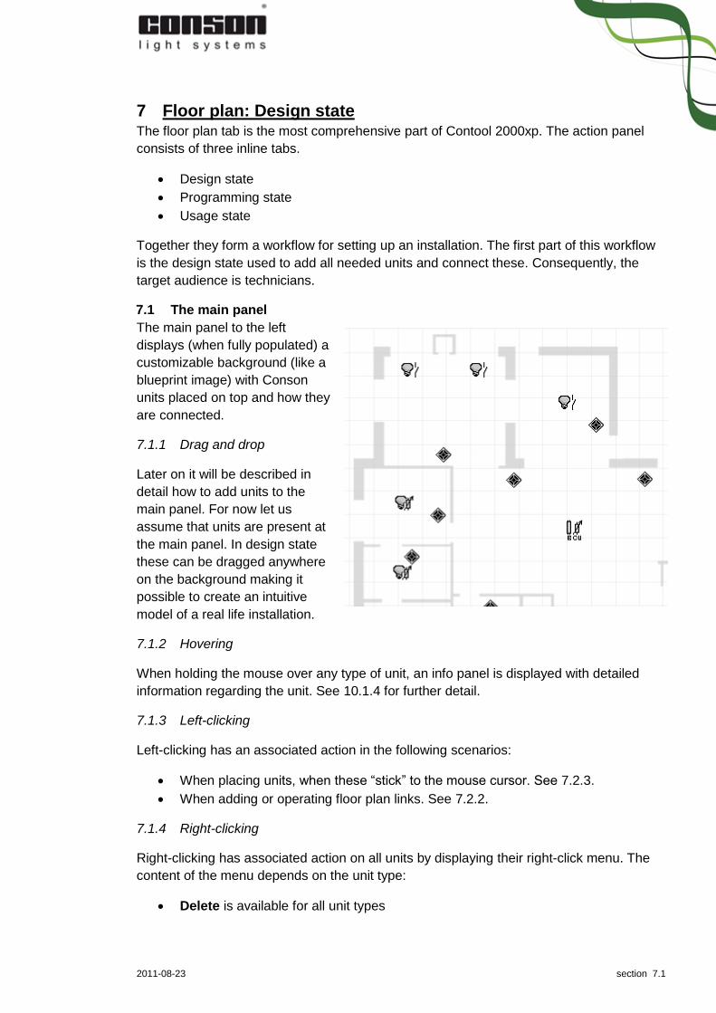
7.1 The main panel
The main panel to the left
displays (when fully populated) a
customizable background (like a
blueprint image) with Conson
units placed on top and how they
are connected.
7.1.1 Drag and drop
Later on it will be described in
detail how to add units to the
main panel. For now let us
assume that units are present at
the main panel. In design state
these can be dragged anywhere
on the background making it
possible to create an intuitive
model of a real life installation.
7.1.2 Hovering
When holding the mouse over any type of unit, an info panel is displayed with detailed
information regarding the unit. See 10.1.4 for further detail.
7.1.3 Left-clicking
Left-clicking has an associated action in the following scenarios:
When placing units, when these “stick” to the mouse cursor. See 7.2.3.
When adding or operating floor plan links. See 7.2.2.
7.1.4 Right-clicking
Right-clicking has associated action on all units by displaying their right-click menu. The
content of the menu depends on the unit type:
Delete is available for all unit types

2011-08-23 section 7.2
Is WAP enabled… is available for all sensors. This will toggle whether the sensor
is part of the WAP access. By default no sensors are part of the WAP access. See
16.1.2 for further detail.
Blink is available for all XP sensors. This will make the unit blink both on the floor
plan as well as the real-life installation making it easy to identity the unit. The menu
item is only enabled if online.
Start rotate is available for all XP sensors. This will the unit enter “rotate mode”
just like pressing the “start listening” in 7.2.4. The menu item is only enabled if
online.
Stop rotate is available for all XP sensors. This will make the unit exit rotate
mode. The menu item is only available if online.
7.1.5 Drawing lines
Lines can be drawn, coloured and deleted anywhere on the floor plan by doing the
following:
Hold down the “W” key on the keyboard to start drawing a straight line from the
original mouse coordinates. Release the “W” to end the line.
Press the “T” key to switch the colour of the latest line. There are 7 different
colours available.
Press the “D” key to delete the latest line, or the “C” key to clear all lines.
The scope of the “T”, “D” and “C” commands are the current floor plan. Consequently,
pressing “C” will only clear the lines on the currently selected floor plan.
All of the above actions only apply if the floor plan is in focus. Do so by clicking anywhere
on the floor plan.
7.2 The action panel
The top part of the action panel in design state consists of four tabs:
1. Floor plans used to add, remove, copy, rename and replace blueprint images
2. Floor plan links used to create links between floor plans
3. Sensors/actors used to add sensors and actors to the floor plans
4. Detect XP sensors used to add detected XP sensor to the floor plans
The bottom part of the action panel in design state is occupied by the “Unit list” in the first
three of the four tabs listed above. The unit list simply displays all placed units (sensors,
actors, modules etc.) in the project. By using the up and down arrows in the middle of the
list is a possible to move units out of the quotation.
The remaining part of this section regarding the design state will focus on the functionality
on the four tabs listed above.
7.2.1 Floor plans
Most of the controls on this tab speak for themselves but these controls used to select a
new floor plan image are worth commenting further:

2011-08-23 section 7.3
In Contool 2000xp it is possible to
use professional blueprints, your
own customized background image
or even room photos for each of the
project floor plans.
For demo purposes Contool
2000xp is shipped with several
blueprints as well as a photo of a
B&O equipped room. These images
will be used throughout the user
manual, but obviously each real life
project should always use real life blueprints/photos supplied by the end user.
Preferably, the image should be the same size as the floor plan view port area. Since it is
possible to resize Contool 2000xp to fit different screen solutions, a fixed size cannot be
set. However, if you use the standard window size of Contool 2000xp, you can import
images with a 650 x 580 pixels resolution. Importing larger images will place scrollbars in
the viewport, allowing you to scroll horizontally/vertically across the entire image.
If you wish to resize a larger image to fit the floor plan viewport, use an image editing
application. Several webpages offer this functionality like http://picresize.com.
Basically the site consists of 3 steps illustrated in the following collage:
Upload image through a simple file chooser
Resize settings (see illustration)
Save image
Default viewport:
580 pixel
Default viewport:
650 pixel
2011-08-23 section 7.4
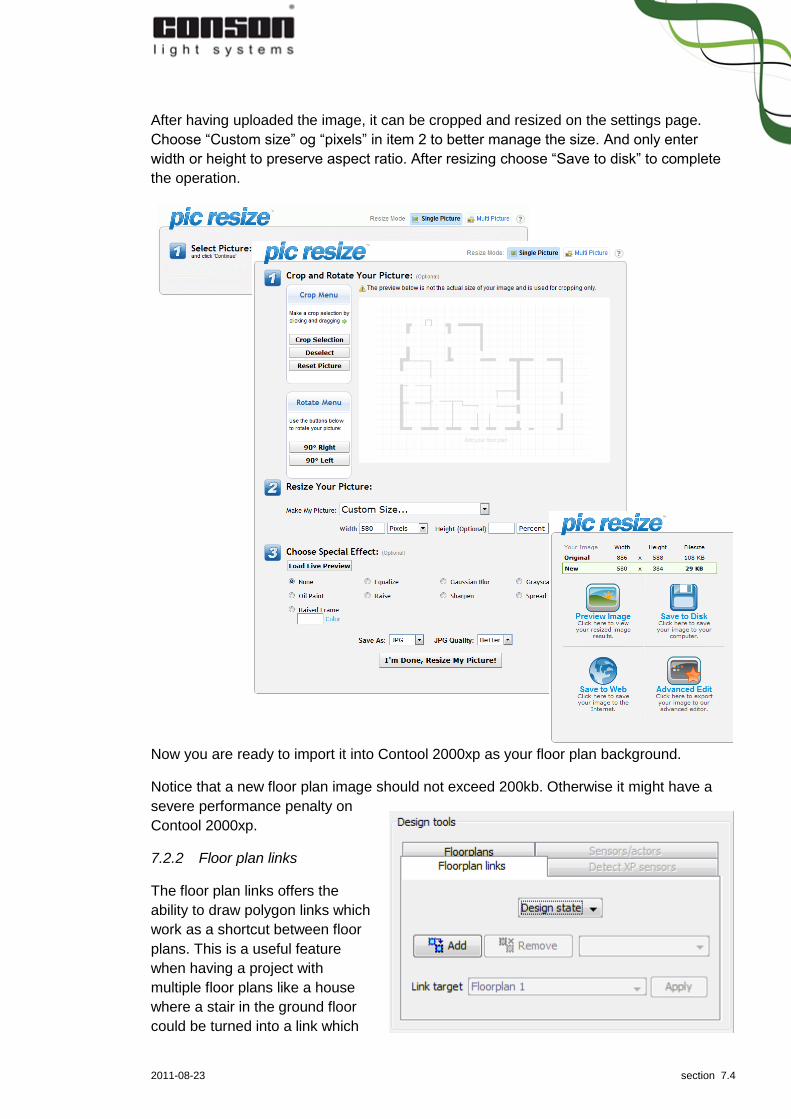
After having uploaded the image, it can be cropped and resized on the settings page.
Choose “Custom size” og “pixels” in item 2 to better manage the size. And only enter
width or height to preserve aspect ratio. After resizing choose “Save to disk” to complete
the operation.
Now you are ready to import it into Contool 2000xp as your floor plan background.
Notice that a new floor plan image should not exceed 200kb. Otherwise it might have a
severe performance penalty on
Contool 2000xp.
7.2.2 Floor plan links
The floor plan links offers the
ability to draw polygon links which
work as a shortcut between floor
plans. This is a useful feature
when having a project with
multiple floor plans like a house
where a stair in the ground floor
could be turned into a link which

2011-08-23 section 7.5
leads to the upper floor.
When created a link, set it in “Design state”, press the “add” button and click on the floor
plan where you want the polygon to start. Each click will create a new edge to the polygon
and dragging the highlighted edges will resize the polygon. The “link target” holds the floor
plan which the polygon will link to.
Finish off by setting the state to “test state”.
7.2.3 Sensors/actors
All units are located on the
“Sensors/actors” tab on drop down
menus. Sensors are units like
push buttons, remotes, PIR
detectors etc. which all trigger
actions on actors which are
outlets, lamps, motors fan, etc.
By clicking a unit, this unit “sticks”
to the mouse cursor which is
moved inside the main panel (the
floor plan to the left). After placing a
unit by left-clicking on the floor plan, a new unit of the same type “sticks” to the mouse
cursor until ESC is pressed or the mouse cursor is moved outside the floor plan area.
Most actors require a connection to a module and some sensors require a connection to
an “eye”. Whether this connection is handled automatically by Contool 2000xp or handled
manually by the user is set in the “Settings” menu by the “Automatic connection” option.
See the sections 8 and 11 for an in-depth description of how to program units.
7.2.4 Detect XP sensors
The “detect XP sensors” tab
replaces the unit list with a list of
detected XP sensors. If the list
does not contain the expected
count of units, press the “Detect XP
sensors” button to make Contool
2000xp try to re-detect sensors.
The list contains information about
serial number and module type in a random order, but in order to place the sensors
correctly on the floor plan it is important to be able to have them displayed in a sorted
order. They can be sorted by pressing the “start listening” and walk around the installation
in a fixed order, pressing the push buttons on the way. Each unit will, when pressed, send
out a timestamp which the application will use to order the units.
2011-08-23 section 7.6
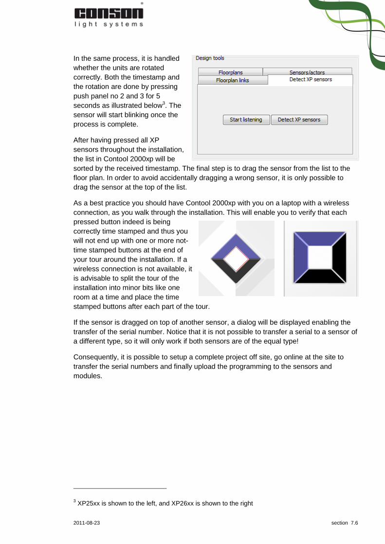
In the same process, it is handled
whether the units are rotated
correctly. Both the timestamp and
the rotation are done by pressing
push panel no 2 and 3 for 5
seconds as illustrated below3. The
sensor will start blinking once the
process is complete.
After having pressed all XP
sensors throughout the installation,
the list in Contool 2000xp will be
sorted by the received timestamp. The final step is to drag the sensor from the list to the
floor plan. In order to avoid accidentally dragging a wrong sensor, it is only possible to
drag the sensor at the top of the list.
As a best practice you should have Contool 2000xp with you on a laptop with a wireless
connection, as you walk through the installation. This will enable you to verify that each
pressed button indeed is being
correctly time stamped and thus you
will not end up with one or more not-
time stamped buttons at the end of
your tour around the installation. If a
wireless connection is not available, it
is advisable to split the tour of the
installation into minor bits like one
room at a time and place the time
stamped buttons after each part of the tour.
If the sensor is dragged on top of another sensor, a dialog will be displayed enabling the
transfer of the serial number. Notice that it is not possible to transfer a serial to a sensor of
a different type, so it will only work if both sensors are of the equal type!
Consequently, it is possible to setup a complete project off site, go online at the site to
transfer the serial numbers and finally upload the programming to the sensors and
modules.
3 XP25xx is shown to the left, and XP26xx is shown to the right

2011-08-23 section 8.1
8 Floor plan: Programming state The programming state enables programming the units placed in design state.
Consequently, the target audience is technicians.
8.1 The main panel
The main panel to the left displays the units placed in design state and the programming
as the programming of the units are created during this state.
8.1.1 Hovering
The exact same information is displayed in programming state as in design state when
hovering. See 7.1.2.
8.1.2 Left-clicking
Left-clicking has an associated action in the following scenarios:
1. When clicking a sensor (except remotes needing an eye)4. This will display a zoom
of the sensor at the action panel.
2. When clicking a remote needing an eye. This will prompt the user to select a
compatible eye and making the selection easy by hiding all non-compatible units.
3. When clicking an empty coordinate on the floor plan. This will exit the state
entered at any of the two items above.
8.1.3 Right-clicking
Similar to the design state, right-clicking any unit will display their right-click menu, and the
content of the menu depends on the unit type:
Module setup… is available for all actors and all XP sensors
Update firmware… is available for all XP actors and all XP sensors. This will open
a dialog with functionality to update the firmware by selecting which firmware
version to update to. The newest firmware files are always shipped with Contool
2000xp. Updating firmware will clear all data in the unit. Hence doing so will mark
the unit for upload in the upload dialog (see 12.2.2 for further details).
View action table… is available for all XP actors and XP sensors and opens a
dialog with the serial number, link number and content of the action table.
Actor console… is available for all XP actors. The functionality is described in
details in 8.1.4.
Actor programming… is available for all XP actors. The functionality is described
in details in 8.1.4.
Setup alert… is available for all XP actors. The functionality is described in details
in 8.1.6.
Configure webcam… is available for webcams. The functionality is described in
details in 8.1.7.
Configure… is available for eyes. The functionality is described in details in 8.1.8.
4 Remotes are by definition also sensors.

2011-08-23 section 8.2
Connect eye… is available for remotes needing eyes. The functionality is
described in details in 8.1.9.
Upload single module… is available for actors. The functionality is described in
details in 8.1.10.
8.1.4 Right-click menu: Actor console…
Selecting the “Actor console…” from the right-click menu opens a dialog with three
features:
1. Enable auto reporting. This is used to enable actor event on “make” and “break”
and is by default turned off to reduce traffic on the bus. If enabled it will
furthermore be used to display the state of the actor in usage state and can be
used in conjunction actor programming. This See 8.1.5 for further details.
2. Enable toggle. This is used to enable/disable the possibly to toggle the actor
directly from usage state (or the dialog itself). See 9.1.1 for further details.
3. Enable light level (only available if the actor is connected to a XP31 or XP33).
This is used to enable/disable the possibly to set the light level directly from the
dialog itself.
8.1.5 Right-click menu: Actor programming…
Selecting the “Actor programming…” from the right-click menu of an XP actor will set the
floor plan in “Actor programming state” which is shown by marking the actor (invoker) with
an orange circle and prompting the user to select a second actor (invokee).
The process is similar to selecting a push panel on a sensor (invoker) and subsequently
selecting an actor (invokee). This is due to the fact that the new Concept 2000xp enables
the actors to fire events on “make” and “break” and this event can be used to trigger
events on other actors. Consequently, when selecting the second actor (invokee) the
regular programming dialog will be shown. To exit the “Actor programming state”, press
the ESC key on the keyboard.
For a complete example on how to utilize actor programming see 11.1
8.1.6 Right-click menu: Setup alert…
The menu item “Setup alert…” opens the dialog below.

2011-08-23 section 8.3
Through the dialog it is possible to have Contool 2000xp sent out an e-mail when a certain
actor is turned on/off e.g. if the outlet at the freezer is turned off.
Be careful to test whether your SMTP server filled in at the bottom of the dialog allows you
to send out e-mails without SMTP Authentication5.
Finally beware that the message type SMS is not implemented in this version.
8.1.7 Right-click menu: Configure webcam…
The menu item “Configure webcam”
opens the regular webcam viewer in
Contool 2000xp. Pressing the “Setup”
button will open another dialog used
configure the stream to display in the
webcam viewer. It is possible to connect
to either a USB camera or an HTTP/IP
camera. The latter is very easy since it is
typically merely a question of filling in the
correct URL and this URL can be tested
by using the external viewer found at the
bottom of the dialog.
The former (USB) can be a little more
tricky. It needs a viewer application which
is usually shipped together with the web
cam. For easy of use a simple viewer is
shipped together with Contool 2000xp at
[installation
path]/USBWebCamViewer/WebCamView
er.exe.
8.1.8 Right-click menu: Configure…
The “Configure…” menu item is only found at eyes and it opens a dialog for setting the
channel (for XP eyes) or for adding and connecting modules with channel and link (for CP
eyes).
8.1.9 Right-click menu: Connect eye…
The “Connect eye…” menu item is used to setup default connections for ease of use in
the usage state.
If no eye is connected to an eye-needing remote control, selecting this remote control in
usage state will prompt the user to select which eye to go through when operating the
remote. This step can be eliminated by setting up a default connection.
5 Verifying this is beyond the scope of this user manual.

2011-08-23 section 8.4
To connect to an eye, select the “Connect eye” menu item on the remote and left-click the
preferred eye. To disconnect repeat the same steps as when connecting. To exit the
“connect eye state” left-click on an empty coordinate at the floor plan.
Notice that selecting more than one eye in the same mode is ambiguous and will not
provide the necessary information to eliminate “the select remote control step” in usage
state.
8.1.10 Right-click menu: Upload single module…
The “Upload single module…” is only found at actors and acts as a shortcut to upload
data to the module which the current actor is connected to. This will open the same
upload dialog used when uploading to multiple units from the Fusebox. Only difference is
the fact that there will always only be uploaded one single module when triggered from
“Upload single module…” menu item.
8.2 The action panel
In order to start working with the action panel, the first step is to select a sensor (by left-
clicking on it) on the main panel to the left. Doing so makes displays a zoom of the
selected sensor.
How to process from here depends mainly on the type of the selected sensor and settings
in the Settings menu. The various paths on how to complete the programming are shown
in the below work flow chart where all paths start by selecting a sensor.
8.2.1 General workflow
This workflow applies to all XP switches, CP switches in automatic connection mode,
CP70C remotes6 and the virtual 70D sensor.
The general workflow is displayed as the series of light blue squares and represents the
shortest path. Since every single step (except the “Select a pushbutton”) is part of any
other path, each step will be explained in details below:
1. Select a sensor from the main panel to the left.
2. Enter placement and rename sensor. Notice that the sensor is already named,
so renaming it is not mandatory.
3. Select a pushbutton on the zoomed sensor.
4. Rename pushbutton. Notice that the pushbuttons are already named, so
renaming them is not mandatory.
5. Select programming method is strictly speaking not part of the shortest path but
it is the most common path since most sensors offers more than one programming
methods. But since a few sensors only have one programming method, the step is
left out in these cases.
6. Select actor on the floor plan by left-clicking on an actor at the main panel which
opens up a dialog.
6 CP70C01, CP70C05, CP70C08 and CP70C16.

2011-08-23 section 8.5
7. Add the preferred function in dialog and press “Ok” button. This dialog is
described in detail in 8.3.
Select a sensor
Select a pushbutton
Select actor on floor
plan
Select programming
method
Add preferred function
in dialog and press
”Ok”
Enter placement and
rename sensor
Rename pushbutton
Select multiple push
panels
Select an eye
Select module and
channel
8.2.2 Alternative workflow: Programming multiple push panels at the same time
It is possible to select multiple push panels in any workflow by holding down the Ctrl key
at the keyboard and select several push panels. Release the Ctrl key after having
selected the preferred push panels and before proceeding to the step “Rename
pushbutton”.
If pushbuttons with conflicting programming have been selected, the following dialog will
appear with the following options (when releasing the Ctrl key):
Copy programming from first selected will delete any programming on all other
push panels than the first selected and copy the programming from the first
selected.

2011-08-23 section 8.6
Delete programming will delete the programming on all the selected push panels.
Cancel will not have any impact besides clearing the selection.
Proceed with step “Rename pushbutton”, unless having selected “Delete programming”.
8.2.3 Alternative workflow: Programming remotes through eyes
This workflow applies for all remotes controls needing eyes to operate7.
These remote controls are easy to spot, since the action panel will display a message to
select an eye after having selected an eye-needing remote control. Furthermore, all non-
compatible units will be hidden, making it easy to select a compatible eye8 at the main
panel. After having selected a compatible eye proceed with the general workflow at “Enter
placement and rename sensor”.
8.2.4 Alternative workflow: Programming by selecting module and channel
CP switches in manual connection mode or just CP switches through XP28 units need
additional steps to complete their workflow. After having selected a programming mode,
controls to select a CP/XP20 or an XP28 will become available. If selecting an XP28, this
can be done in the dropdown list or by selecting the XP28 directly on the main panel.
Selecting the channel is last part of the step which is done by left-clicking the preferred
radio button. Selecting the channel is not enabled if having selecting the programming
mode “All on” or “All off” and a CP20/XP20 module due to the fact that this programming
mode is set at fixed channels.
The background colour of each channel indicates whether the channel is vacant or not
and more in-depth information is available in an info panel when moving the mouse cursor
over each channel:
Green symbolizes vacant
Red symbolizes non-vacant and the info
panel will display link and input number
alongside with a list of all sensor
connected with the channel.
Finally notice that when selecting a channel
which is already programmed through another connected sensor, the existing
programming will be displayed. And changing the functionality will affect all sensors
connected to that channel.
8.2.5 Alternative workflow: Custom programming of all on/all off
7 Either a BeO4 or a CP79
8 If the remote is a BeO4 select one of the following eyes: XP 2506B, XP 2606B, CP 2502B, CP
2507B, CP 2509, CP 2602B, CP 2607B, CP2609 If the remote is a CP70 select one of the following eyes: XP 2506A, XP 2606A, CP 2502, CP 2507, CP 2602, CP 2607

2011-08-23 section 8.7
All on and all off are built-in function collections of switch on and switch off functions,
respectively. All actors are by default included in these function collections with exception
of motors (since they take up two or more outputs).
Changing the default all on/all off programming is possible by following the general
workflow right up until the final step (the programming dialog). This dialog contains
“Member of all on”/”Member of all off” checkboxes – se 8.3.1 for further details.
Unchecking these checkboxes will obviously remove the actor/output from these built-in
function collections but furthermore it will enable the controls at the programming section
of the programming dialog (se 8.3.2) and thus make it possible to add custom
programming to be executed alongside the default. This is useful when wanting to leave
the light at the front door on for a couple of minutes after having turned all other light off.
Checking the “Member of all on”/”Member of all off” checkboxes will delete any custom
programming and re-add the default programming.
8.3 The programming dialog
The programming dialog is the final step of any programming workflow and consists of:
The name of the actor.
A number of tabs equal the number of output occupied by that actor. If an output is
named at the fusebox, the name will be displayed right after the output number
(like “red cable” in the example).
A settings section (marked in red)
A programming section (marked in yellow)
8.3.1 The settings section
The “member of all on/all off” checkboxes are checked by default indicating that all actors
by default are included in the all on/all off sets. Changing this setting will remove/add the
output to the set.
“Auto reporting” is the same functionality
as described in 8.1.4. By default it is not
enabled.
“Push panel feedback” triggers the LED
in the selected push panel when the
actor connected to the current output
changes state (is turned on/off). This is
accomplished by having the push panel
listen for this change which is indicated
by the auto reporting telegram.
Consequently, checking the “push panel
feedback” will automatically check the
“auto reporting”.
8.3.2 The programming section

2011-08-23 section 8.8
The programming section enables the use of function with parameters which can be
added, removed or sorted. Several functions can be added to any output and it is solely
the user’s responsibility to add compatible functions.
8.4 The sensors
Since the type of the sensor has such a great impact on how the work flow goes, let us
have a closer look the sensors. The sensors can be categories based on differences in
their functionality. The ultimate responsibility of all sensors9 is to broadcast a telegram
(when activated) which is a combination of their type, a link number (tied to the unit) and a
channel number (tied to a push panel or similar). This is important due to the fact that
there are constraints on these combinations:
In the Concept 2000 (CP series) a maximum of 4 different link numbers per type
are available.
In the Concept 2000xp (XP series) a maximum of 100 different link numbers per
type are available. One of these link numbers are reserved which leaves a
maximum of 99 units of the same type.
For guidelines on how to program these sensors see section 11 for further details.
8.4.1 XP sensor
The sensors named XP 2506 and XP 2606 are XP sensors. Both of them have variants
with a B&O eye10 (named with a post fixed B) or an IR eye11 (named with a post fixed A).
An XP sensor holds both module type, link number and channels numbers in itself as well
as push panels and can be programmed without being dependant of any other units. This
is also the case with the A and B variants, which have built-in “eyes”.
The input number is “built-in” each individual push panel
8.4.2 XP28
The sensors named XP 28 are XP 28 type sensors – and like the XP sensors they come
in A and B variants.
Even though the XP28 sensors are very closely related to the XP sensors, there is one
major difference: XP28 sensors have no push panels. Consequently, push panels from
“non-programmable” sensors must be wired to an XP 28 sensor in order to operate it.
8.4.3 B&O
In Concept 2000 B&O integration is possible through a “B&O eye” in a sensor12 and a CP
70B module. In Concept 2000xp this is still possible (all though the module to use is called
XP 70B). Both of these modules are programmed using Conbeam/XP78.
9 If the sensor is a CP sensor, the responsibility to broadcast the telegram is actually the module,
which the sensor is connected to. 10
XP 2506B, XP 2606B 11
XP 2506A, XP 2606A 12
CP 2502B, CP 2507B, CP 2509, CP 2602B, CP 2607B, CP2609

2011-08-23 section 8.9
The preferred way is to simply use a B variant of an XP sensor or XP 28 sensor which
holds both the needed eye as well as the module-functionality.
8.4.4 UHF
In Concept 2000 UHF integration is possible through the CP 70C module. In Concept
2000xp UHF integration is very similar through the XP 70C module. Both of these
modules are programmed using Conbeam/XP78.
8.4.5 IR
The IR integration is (from a sensor/module point of view) very similar to the B&O
integration:
In Concept 2000 IR integration is possible through an “IR-eye” in a sensor13 and a CP 70A
module. In Concept 2000xp this is still possible (all though the module to use is called XP
70C). Both of these modules are programmed using Conbeam/XP78.
The preferred way is to simply use the A variant of an XP sensor or XP 28 sensor which
holds both the needed eye as well as the module functionality.
8.4.6 Timer
There is no actual real life sensor available for the timer type, due to the fact that it only
consists of a module. But since everything programmable in Contool 2000xp must be
accessed through a unit on the floor plan, a virtual sensor for 70D is added.
Like B&O, UHF and IR both a CP 70D and a XP 70D modules exist and both are
programmed using Conbeam/XP78.
8.4.7 CP programming (XP20)
The Concept 2000 general way to program most functionality (by placing a sensor and
connecting this sensor to a CP20 module) is still supported in Contool 2000xp. The
connection from the sensor to the module can now also be done with an XP 20 module.
13 CP 2502, CP 2507, CP 2602, CP 2607

2011-08-23 section 9.1
9 Floor plan: Usage state The usage state is the third and final state where all units have been placed, connected
and programmed. The state merely contains functionality to operate the units.
Consequently, its target audience is the end user.
9.1 The main panel
The main panel looks identical to the previous two states, but the functionality differs.
9.1.1 Left-clicking
It is possible to left-click both sensors and actors:
Left-clicking a sensor brings up a zoom of the sensor at the action panel. See
9.2.2.
Left-clicking an actor toggles the actor – if a toggle is available through a
programmed function and if toggle is enabled (see 8.1.4).
9.1.2 Double-clicking
Double-clicking a webcam will open a dialog displaying the webcam viewer.
9.1.3 Actor feedback
If the actor is set to send feedback, operating a function in any way14 will change the icon
of the actor to illustrate its state (on or off).
9.2 The action panel
The action panel in usage state consists of the parts:
1. Miscellaneous which enables the end user to operate two different set of actions:
a. Custom actions which operate external programs outside Contool – like
opening websites and locally installed programs. These actions are
editable.
b. Special Contool integrated functions which operates functionality within
Contool. These actions are not editable.
2. Sensor which enables the end user to trigger programming in Contool 2000xp as
if pressing the physical push panel.
9.2.1 Miscellaneous
Contool 2000xp is shipped with language specific template functionality for the
miscellaneous section in usage state. When creating a new project, the template for
chosen language is copied to the project.
Consequently, changing language after the project is created will not change anything in
this section, since it is bound to a copy of the selected language template at creation of
14 There are three ways to operate an actor:
1. In usage state by left-clicking the actor 2. In usage state by left-clicking a push panel on the zoomed sensor in the action panel 3. In real life by pushing a push panel on a physical sensor.

2011-08-23 section 9.2
the project. The template contains for instance examples of links to webpages (for grocery
shopping) and lists of freezer content in both Excel and Open Office formats.
Graphically, the sections hold 3 x 6 buttons where each of these buttons can control one
or more actions. The default layout
is shown below.
When left-clicking one of the 18
controls, one of the following will
happen:
If there is no action
defined, merely the
message “No functionality
has been specified for this
button” will be displayed.
If there is only one custom action defined, this action will be initiated. In revision
2670 the actions can be either opening a webpage or a locally installed
programme from a URL.
If there is more than one custom action defined, a popup list will be displayed
with all the actions. Double click the wanted action.
Furthermore the three buttons marked in a red square are populated with special
Contool integrated functions which are only operational if on custom action is
defined on the button:
o The alarm clock enables an alarm to be set at a fixed point in time (within
24 hours)
o The time glass enables a countdown (within 24 hours)
o The key lock holds a simple (key)lock for Contool
When right-clicking a control you will get the following options:
“Change icon” used to change the icon by picking another image located on the
computer. This action is always available.
“Delete URL” used to delete the action on the control. This is only available if there
is only one action defined on the control.
When right-clicking an item in the popup list, you will get the following options:
“Delete item” used to delete the selected action
“Edit name” used to rename the selected action.
It is possible to drag and drop a URL for instance from the address field of the browser
window to one of the 18 controls in the usage state in Contool. By doing so, the URL will
be saved as a new custom action and added to the bottom of the list. By dragging the
complete path of a locally installed programme or document (like C:\Program
Files\Microsoft Office\Office12\Outlook.exe) it is also possible to add this as a custom
action.
In the popup list the items/actions can be sorted by dragging them to a new position.

2011-08-23 section 9.3
9.2.2 Sensor
Clicking a sensor on the floor plan to the left brings up a zoom of the current sensor.
Pressing the push panels of this sensor will make Contool 2000xp trigger functions on the
live modules – as if you were pressing the same push panel in real life!
But notice that this is the default behaviour which can be change in the Settings menu.
See 10.1.6

2011-08-23 section 10.1
10 Floor plan: The settings menu The Settings menu found at the top menu in
Contool 2000xp contains a series of application
wide settings. Items enclosed in green are solely
related to the floor plan, and they are shown with
their default settings.
10.1.1 Invert function
When selected, the “Invert function” will become
visible at the programming dialog offering the
possibility to invert a programmed function. See
11.1.3 for further detail.
10.1.2 Automatic connection
When selected, the “Automatic connection” makes
it faster to place and program units since the user
is no longer prompted to make some of the
detailed decisions.
In design state, the user is not prompted to choose at which output at which module to
connect an actor if placing an actor. Contool 2000xp will automatically choose the first
vacant output at the first suitable module, and if no module is present a new module will
automatically be added. The same kind of logic applies when placing a unit with a B&O
eye or an IR eye: if “Automatic connection” is selected, Contool 2000xp will not prompt
you to select the channel on which the eye should look for data.
In programming state, the user is not prompted to choose at which input at which
CP20/XP20 module to connect a push panel to if programming a CP sensor.
In order to have full control over these decisions deselect the “Automatic connection”.
10.1.3 Show connection lines
When a push panel is programmed to affect one or more actors, a connection line will be
shown between the sensor and the actor/actors and all the units will be circled.
If a programmed sensor is selected, all the units affected by the sensor will have their
connection lines displayed. When hovering or
selecting a push panel, only the units affected by
that push panel will have their connection line
displayed.
Connection lines are shown in programming and
usage state if the menu item “Show connection
lines” is selected.
10.1.4 Show info panels
When selected, the “Show info panels” will display a

2011-08-23 section 10.2
panel with text on a grey background. The information on the panel is always displayed
when a unit is hovered on the floor plan image to the left. But the content of the info panel
will vary depending on the following:
Any unit will display its name in any state.
o In design and programming state actors will furthermore display details
regarding their connected module
o In design and programming state sensors will display their placement text
and XP sensors will furthermore display their serial and link number.
If a push panel on the action panel to the right is selected, the info panel will
besides the above listed information display details regarding the programmed
functions from the selected push panel. This is the case in both programming and
usage state.
10.1.5 Fire on select in programming state
By default when clicking a push panel in programming state, the push panel is selected.
This setting can be used to change the default behaviour to fire the function instead
(making it work like the default setting in usage state)
10.1.6 Fire on select in usage state
In usage state the default setting is opposite the setting in programming state: By default a
function is fired by clicking a push panel, but it can be changed to selecting the push panel
instead. This is useful for showing full details in info panels like described in 10.1.4 for
further details.

2011-08-23 section 11.1
11 Programming examples for the XP series
11.1 Exhaust fan
This short guide describes how a bathroom
exhaust fan can be programmed with
Contool. A normal way to control a bathroom
exhaust fan is to have it running on a timer,
delaying start and stop with respect to the
bathroom light. This is done in Contool using
Auto report events, actor programming and
invert function.
11.1.1 Auto Report Events
Each actor can send out an event when the
status of one of its outputs changes.
This must be enabled in the Actor Console
(Right-click lamp, choose “Actor Console”,
and check the “Enable Auto Reporting” flag).
You can only do this while online with the
system.
11.1.2 Actor Programming
To use the auto report events from a lamp (actor) to invoke functions on your fan, right-
click the lamp and choose “Actor Programming”.
Now choose the actor
(Fan) that should be
controlled with respect to
the bathroom light. This
will give you the usual
programming dialog.
11.1.3 Invert function
You must have access to
the invert function to
program the fan, so make
sure the ”Invert function”
is checked in the
”Settings” menu.
Auto report events come
in two flavours: A “make”
event when the actor
switches on, and a “break”
event when the actor
switches off.

2011-08-23 section 11.2
The Invert checkbox lets you choose which event should invoke this particular function. If
the Invert checkbox is checked, the “break” event is used to invoke the function, if
unchecked, the “make” is used (this is the normal situation).
To turn on the fan, the ”On After” function is used with a time parameter specifying the
delay from the bathroom light turns on, to the fan is turned on.
To turn off the fan, the “Off” function is used with a time parameter specifying how long
time the fan should run after the bathroom light is turned off. This function must be
triggered by the “break” event.
On the figure above you can see the entire programming of the fan. Press “Ok” as usual
when done, and you will see a link between the bathroom light and the fan, just as you
would between a sensor and a lamp.
11.1.4 A note on the Fan symbol and XP24/XP24P
When designing floor plans, the fan symbol uses an XP24 module. If you want to run the
fan from an XP24P module, turn off “Automatic Connection” in the “Settings” menu. You
will then be able to connect the fan to either an XP24 or an XP24P.
11.2 Curtain control
In Contool you have some actor symbols used for controlling curtains and blinds. In this
section we will look at how they are used.
11.2.1 Curtain actors
In design state you find the motors for curtain control under the XP tab by pressing the
motor button.
There are two standard AC motors, using two relays from either an XP24 or an XP24P
(power registration). The relay pairs (1-2 and 3-4) will be mutual exclusive, with a dead
time of 300ms. The dead time can be changed using the “Direct programming” dialogue,
see illustration below in this section.
Furthermore there is one DC motor using four relays from an XP24, and finally a simple
fan motor, using one relay from an XP24. If you need XP24P for fan control, disable
automatic connection in the “Settings” menu.
11.2.2 Programming Curtains
We will describe programming curtains using an example: We have a curtain and an up-
button and a down-button. We want to be able to stop the curtains at any time. If we for
instance press “Up” while the curtain is already moving in that direction, we want it to stop.
So both the “Up” and “Down” button must do “up-stop-up” and “down-stop-down” when
pressed multiple time.
We also want the relays to go off after one minute, to remove power supply from the
motor when not needed.
Say the up direction is controlled by Relay 1 (Output 1) of the XP24, and the down
direction by output 2.

2011-08-23 section 11.3
To program the desired function, in programming state select a push panel from the floor
plan, then select the button that should be used for ”Up”. Click the motor and add “Toggle
1 min”15 on the “Output 1” tab. Then select the “Down” button on the sensor, and click the
motor again. Now select the “Output 2” tab, and add another “Toggle 1 min” function.
Below is shown how the programming looks in Contool.
11.2.3 All on/All off functions with curtains
In the programming dialogue, notice that curtain relays are not default members of the “All
on” or “All off” group the way a normal lamp is. This is because the system cannot know
what “All on” or “All off” should mean for a curtain – should it go up or down, using which
relay?
The All On/All Off functionally has to be added manually. In this example we want the
curtains to go up on when “All off” is pressed.
To do this, select one16 of the “All off” buttons, click the curtain actor on the floor plan
which will bring up the programming dialogue. Now select the output 1 tab (output 1 was
15 Giving the toggle function a time parameter will restrict its “on” time to the time parameter.
16 You only need to select one of the “All off” buttons for this programming, even though you might
have several “All off” buttons in your system. This is because each button which has the “All off”
2011-08-23 section 11.4
the “up” relay remember), and add the function “On 1 min” to the tab. With this function,
the relay 1 (Up relay) will go on for 1 minute each time an “All off” button is pressed.
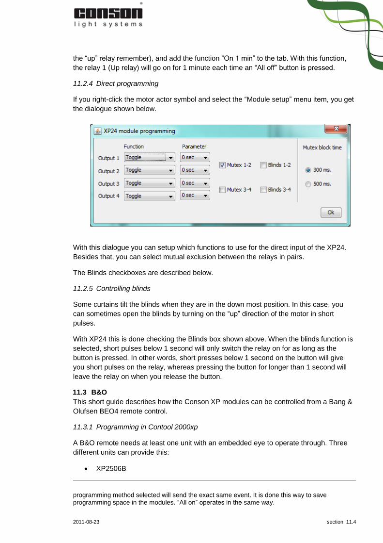
11.2.4 Direct programming
If you right-click the motor actor symbol and select the “Module setup” menu item, you get
the dialogue shown below.
With this dialogue you can setup which functions to use for the direct input of the XP24.
Besides that, you can select mutual exclusion between the relays in pairs.
The Blinds checkboxes are described below.
11.2.5 Controlling blinds
Some curtains tilt the blinds when they are in the down most position. In this case, you
can sometimes open the blinds by turning on the “up” direction of the motor in short
pulses.
With XP24 this is done checking the Blinds box shown above. When the blinds function is
selected, short pulses below 1 second will only switch the relay on for as long as the
button is pressed. In other words, short presses below 1 second on the button will give
you short pulses on the relay, whereas pressing the button for longer than 1 second will
leave the relay on when you release the button.
11.3 B&O
This short guide describes how the Conson XP modules can be controlled from a Bang &
Olufsen BEO4 remote control.
11.3.1 Programming in Contool 2000xp
A B&O remote needs at least one unit with an embedded eye to operate through. Three
different units can provide this:
XP2506B
programming method selected will send the exact same event. It is done this way to save programming space in the modules. “All on” operates in the same way.

2011-08-23 section 11.5
XP2606B
XP28B
After having placed a BEO4 and at least one unit with an embedded eye17, select the
BEO4 and afterwards select an eye. This will display a zoom of the BEO4 at the action
panel to the left.
The channel group configured at the eye determines which key combinations are
available. By default the channel group is set to 0. This can be reconfigured by right-
clicking the eye and selecting “Configure”:
Channel group
Available key
0 Symbol keys (5 combinations)
Green
Yellow
Blue
Red
Stop Numeric keys 0 – 11 combined with action keys (60 combinations)
Wind [˃˃]
Rewind [˂˂]
Step up [˄]
Step down [˅]
Go
12 Numeric keys 12 – 23 combined with action keys (60 combinations)
24 Numeric keys 24 – 35 combined with action keys (60 combinations)
36 Numeric keys 36 – 47 combined with action keys (60 combinations)
48 Numeric keys 48 – 59 combined with action keys (60 combinations)
The symbol keys are operated by themselves like any other push panel
on a sensor.
Numeric keys can either be one or two digits combined by an action
key. The numeric first key will be marked in blue, the second will be
marked in green, and the action key will be marked in red.
Consequently any numeric key combination is available in 5 variants –
and since a channel group decodes 12 numeric key combinations 60
functions are available with each eye18.
After having selected a key combination, continue programming by
selecting an actor like with any other sensor.
11.3.2 Operating the real-life BEO4 remote control
To control the lights the BEO4 must be in the LIGHT mode. To enter
this mode, press the [LIGHT] button. Subsequently operate the remote
17 The following units contain an BEO4 eye: XP2506B, XP2606B, XP28B
18 65 for channel group 0, since it also decodes the 5 symbol keys.

2011-08-23 section 11.6
just like when programming the remote in Contool 2000xp.
To summarize the following key combinations are available:
[LIGHT] + [SYMBOL KEY]
[LIGHT] + [NUMERIC KEY(S)] + ACTION
It is not necessary to press the [LIGHT] key if the remote is already in light mode. And
when operating functions on the numeric key 0, this key can be left out, since it is the
default. Consequently operating consecutive function on key 0 can be done by only
pressing action keys.
11.3.3 Programming example
Say you have 3 lights in a living room, controlled by the Conson XP33 3-channel light
dimmer.
The lights are numbered 1, 2, 3, and you want to control the lights both individually and as
a group, using the [˄] for light up, [˅] for light down and (GO) for off.
The group functions are added to key group 0. In Contool programming press [0] followed
by [˄] on the BEO image to the right, and add the increase level function to each of the 3
lights. Then press [0] followed by [˅], and add the decrease function to each light. Finally,
press [0] followed by (GO) and add the off function to each light.
Then press [1] followed by [˄], and add a level increase function to light 1. The rest is
programmed in the same manner.
Now all 3 lights can be controlled together with group 0, for instance increasing light level
for all lights are done pressing [LIGHT] followed by [˄]. To decrease light for light 3, press
[LIGHT]19, [3] and [˅].
11.4 Programming with help function, group on/off and short/long
An often needed function is to operate a group of outputs synchronously when turning
them on or off. If the outputs are only operated by a single push panels a simple “toggle”
function will do the job.
But often outputs are operated by several push panels (on
several sensors) and thus they might not be in the same
state when wanting to turn them on or off. To exemplify:
the two lamps above the kitchen table can individually be
operated by the two sensors on each entrance to the
kitchen. But they can also be operated simultaneous from
one of the sensors.
In order to ensure that outputs will operate synchronously, the “help function” found at the
regular programming dialog should be added to each output. The help function will turn
the output on when receiving a “make” and turn the output off when receiving a “break”.
Normally a “make” will be sent when pressing the push panel and a “break” will be sent
19 You do not need to press [LIGHT] if the remote control is already in “LIGHT” mode.

2011-08-23 section 11.7
when releasing the push panel. Consequently, the outputs will turn on and off at the push
of a panel, which is probably not the desired functionality.
This default behaviour can be configured by right-clicking the sensor, selecting the
“Module setup…” option and thus displaying the following dialog:
The first row of the dialog holds the
numbers 1-8 which symbolises the
possible 8 inputs of the XP25, XP26
and XP28 series.
The wiring to XP28 is done manually
which makes the mapping between the
numbering of the channels in the
dialog and the real life sensor explicit.
In the XP25 and XP26 series the
wiring is done under the covers. The
mapping is shown in the illustration
below:
The second and third row of
checkboxes at the dialog holds
configuration for “short/long” and
“group on/off”.
11.4.1 Fundamentals of group on/off
Group on/off basically changes the default behaviour of the push panel by splitting the
“make” and “break” event across two push evens:
The first time the push panel is pushed it will send a “make” event – but no event,
when the push panel is released.
The second time the push panel is pushed it will send a “break” event – but no
event, when the push panel is released.
Consequently, by using the group on/off in conjunction with the help function this will
make the outputs turn on and off in perfect synchronisation.
11.4.2 Fundamentals of short/long
Short/long basically changes the default behaviour of the push panel by splitting the
“make” and “break” event across two push events:
A short event: If a push panel is pushed and released within 300 milliseconds,
it will send out a “make” (but no “break”) event.

2011-08-23 section 11.8
A long event: If a push panel is pushed and released after 300 milliseconds, it
will send out a “break” (but no “make”) event.
Consequently, by using the short/long in conjunction with the help function this will make
the outputs turn on and off in perfect synchronisation
11.4.3 Fundamentals of invert
The first row of checkboxes at the dialog holds the configuration for “invert”. Checking
“invert” for a channel will invert the default behaviour at this channel:
The default behaviour will be changed to “break” event at push and “make” event
at release of a push panel
The short/long behaviour will be changed to “break” for a short event and “make”
for a long event
The group on/off will also be inverted, but this will have little impact since it is
basically a cyclic sequence stepped through by repeating the same action
(pushing and releasing a push panel).

2011-08-23 section 12.1
12 Fuse box Modules can be added to the fuse box in four different ways:
1. When sensors/actors are added to the floor plan which requires a module and no
vacant modules are available. See 7.2.3 for further details.
2. When modules are added manually using the “Add…” button and dialog located at
the action panel associated with the fuse box tab.
3. When detecting modules which only apply to XP 24, XP 31 and XP 33 modules.
See 6 for further details.
4. When downloading module data using the download button and dialog located at
the at action panel associated with the fuse box tab.
In either case, added modules are placed at the first vacant slot20 which most likely does
not match the real life fuse box.
12.1 Moving modules around
In order to make the virtual fuse box in Contool 2000xp match the real life fuse box, the
first step is to identify the module.
This will probably not match the placement in the real life fuse box but it is easy to move
the modules around. First, identify which module to move. This can be done in two ways,
depending on whether it is a Concept 2000 (CP) or Concept 2000xp (XP) module.
12.1.1 Identifying a CP module
If it is a CP module, the only identification possible is by using the module number field
found at the top right corner of the module panel. Consequently, it is important to be very
careful to update this field correctly when adding CP modules.
12.1.2 Identifying an XP module
If it is an XP module it is a lot easier. By pressing the thumbnail of the
module, it will start blinking – both in the real life fuse box as well as the
fuse box in Contool 2000xp.
12.1.3 Moving a module
After having identified a module, it can be moved by pressing the surrounding grey panel,
which will highlight the selected panel as shown below. The highlighted panel is the
“source” panel and pressing the surrounding grey panel on another module (the
“destination” panel) will make the two panels swap place. This can also be done with an
empty slot. If you accidentally press the wrong source module, simply press the module
again21.
20 From the top left corner to the bottom right corner
21 In order to swap it with itself.

2011-08-23 section 12.2
12.1.4 Replacing a broken module
If you need to replace a broken module in a running installation, this can easily be done by
following these steps:
If the module is an XP module
1. Start the project in offline mode
2. Change the serial number (at the top of the module like “0020012508”) to match
the serial number of the new module.
3. Save the project and disconnect
4. Replace the module at the real life fuse box
5. Start the project in online mode. In the start up process, the new module will be
detected, but since it already exists on the fuse box (due to that fact that the old
module has just had its serial number updated)
6. Upload data to the module. It is only necessary to upload data to the newly
replaced module.
If the module is a CP module
1. Replace the module at the real life fuse box
2. Start the project in online mode
3. Upload data to the module. It is only necessary to upload data to the newly
replaced module.
12.2 Uploading data to modules
The upload section is placed at the bottom of the action panel (just above the download
section). The upload section is responsible for transferring data from Contool 2000xp to
the modules (and the XP sensors).
12.2.1 Installing and detecting the Conbeam (XP78)
If you need to transfer data to modules from the old Concept 2000 series or the newer XP
variants22, you will need to first install the Conbeam driver which is shipped with Contool
22 XP20, XP70A, XP70B, XP70C or XP70D

2011-08-23 section 12.3
2000xp. Go to the [installation folder]/ConbeamUSBDriver/ and locate the appropriate
driver in a subfolder matching your operating system. Please refer to the installation
guides in these folders on how to install the driver.
Once the driver is installed, all you need to do in order to detect the COM port is to press
the “Detect” button, which is located in the upload and download dialog displayed after
having pressed either of the two buttons. The detected COM port will be entered in the
text field by the application. If you know the COM port, you may also enter the information
yourself instead of pressing the detect button.
12.2.2 Selecting data to upload
Pressing the “Upload” button will
display a dialog containing a tree view
of all programmable units in the project.
The tree view is organized in two sub
trees:
XP78
XP130
The XP78 sub tree is only present if
any units requiring upload through the
Conbeam23 are present and has non-
conflicting module numbers.
The XP130 sub tree is only present if
any units requiring upload through the XP130 are present and these units have a valid
serial number. All XP actor modules and all XP sensors are placed in the XP130 sub tree.
Both XP78 and XP130 units have an extra level assigned to them: this level displays
information of which units are connected to their inputs (for sensors) or outputs (for
modules). This information is available to enhance the overview of each unit.
Moving the mouse over a XP sensor on the list (like “0020012497 – XP2606, Floor plan
1”) will make the application switch to the floor plan containing that specific XP sensor and
mark it by displaying its info panel.
The bottom section named “Conbeam upload method” is only of interest if uploading
through the Conbeam (XP78). Besides the COM port described in 12.2.1 it holds two
options:
“Module”: to send the data directly to each modules
“Conkey”: to send the data to the XP79/Conkey. Afterwards, this can be used to
transfer the data to each individual module by hand.
23 Units from the old Concept 2000 and new XP variants: XP20, XP70A, XP70B, XP70C or XP70D

2011-08-23 section 12.4
Contool 2000xp keeps track of which units are in need of being updated and these will
already be selected when opening the dialog. It is possible to change the selection but
usually it is recommended to let the application handle which units to update.
If an installation behaves in an unexpected manner, uploading all units is advisable in
order to make sure all units are in sync with data in Contool 2000xp. Do so by selecting
the top nodes of the tree view and press “Ok”.
12.2.3 Uploading data (XP130 and XP78)
Most of the upload process is fully
automated and all you need to do is to
wait for it to finish. When doing so, you
can see the progress at the progress
bar in the upload dialog.
Underneath the progress bar two tables
list complete and incomplete units.
Complete units are unit which have
successfully completed their upload
while incomplete units have failed
during their upload.
Pressing the abort button will abort the
remaining upload – but it will not roll
back changes and leave the real life
modules/sensors in a non-consistent
state.
The upload runs in the following order
1. XP130 transferring data
a. XP modules
i. Action tables for
each module
ii. Setup data for each module
iii. Contool data for each module
b. XP sensors
i. Action tables for each sensor
ii. Setup data for each sensor
iii. Contool data for each sensor
2. XP78 transferring data
a. Action tables for each CP module
Without going into too must details, the “action table” holds the programming created in
the floor plan by selecting which action a sensor event (like the push of a push panel) will
have on an actor.
The “setup data” is the setup made by right-clicking an actor on the floor plan (or a
module on the fuse box) and selecting “Module setup…”

2011-08-23 section 12.5
The “Contool data” is the most critical data needed to restore a Contool 2000xp project if
the project file is lost. Only the modules and sensors programmed through XP130 are able
to store the data needed to restore a project.
12.2.4 Uploading data (XP78)
Before uploading each module
through XP78, Contool 2000xp will
prompt the user to place the
Conbeam at the module.
If a connection cannot be
established to the module, the user
will be prompted once again to
move the Conbeam. The
connection is very sensitive to both
a correct placement over the
module as well as direct sunlight or
similar.
Placing the Conbeam at the 2nd
groove from the left at the module
and keeping a distance of about
half a centimetre from the top edge
of Conbeam to the module usually
works well.
The retry dialog also holds the option to skip or to abort. By pressing skip the current
module will be skipped while moving to the next module in line. By pressing abort all
remaining modules will be skipped.
Notice that either option will result in
an incomplete upload with no option to
roll back the upload done to the
modules/sensor prior to skipping or
aborting.
12.3 Downloading data from modules
The download section is located at the very bottom of the action panel. Download of data
is basically only a last resort if the project file is lost. But it is a very powerful feature since
it offers the possibility to restore a project from the most critical data stored in the
modules.
Notice that downloading data can only be done in a blank project with no actor or sensors
added to the floor plan24!
Enough data is stored in the XP modules/sensors to automatically restore a project, while
only the basic data is stored at the CP modules. The table below shows exactly which
24 When starting a blank project, all XP modules and sensors will be detected. This is fine as long
as no sensors (or actors) are added to the floor plan.

2011-08-23 section 12.6
data is restored from the two different types. The “action tables” contain the programmed
functions, while the “setup data” holds the direct programming”. The “coordinates…”,
“naming…” and “connected…” are also known as Contool data.
The “naming” and “connected actors” are not stored in the CP modules, but at the end of
the download a wizard guides you through entering this information for the CP units.
As the table shows not all data are available:
Naming of the units, the push panels on the sensors and the output of the modules
are available for the new Concept 2000xp units, but only at a maximum length of
24 characters.
Only the first push panel at any channel at an XP28 will be restored.
The floor plan image will not be restored. Even though the units are placed on their
previous coordinates, the background image is not present. Yet it is possible to
upload a (backup of the) image which will replace the default image.
The restored units will be part of the quotation but any discount, extra added units
etc. will not be restored.
The project settings and the name of the project will not be restored either. Notice
that all settings in the “Settings” menu are global for the entire application and
hence not project related.
Actio
n t
able
s
Se
tup
data
Co
ord
inate
s o
n f
loor
pla
n
/fu
se b
ox
Na
min
g (
ma
x. le
ng
th o
f 2
4)
Co
nn
ecte
d a
cto
rs/s
ensors
Flo
or
pla
n im
age
Qu
ota
tio
n
Pro
ject
sett
ings
XP modules/sensors • • • • • CP modules • • (•) (•)
Pressing the “Download” button will bring up a dialog with the option to download in three
different modes:
Tree
CP Interval
CP anonymous
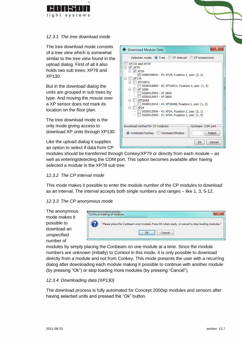
2011-08-23 section 12.7
12.3.1 The tree download mode
The tree download mode consists
of a tree view which is somewhat
similar to the tree view found in the
upload dialog. First of all it also
holds two sub trees: XP78 and
XP130.
But in the download dialog the
units are grouped in sub trees by
type. And moving the mouse over
a XP sensor does not mark its
location on the floor plan.
The tree download mode is the
only mode giving access to
download XP units through XP130.
Like the upload dialog it supplies
an option to select if data from CP
modules should be transferred through Conkey/XP79 or directly from each module – as
well as entering/detecting the COM port. This option becomes available after having
selected a module in the XP78 sub tree.
12.3.2 The CP interval mode
This mode makes it possible to enter the module number of the CP modules to download
as an interval. The interval accepts both single numbers and ranges – like 1, 3, 5-12.
12.3.3 The CP anonymous mode
The anonymous
mode makes it
possible to
download an
unspecified
number of
modules by simply placing the Conbeam on one module at a time. Since the module
numbers are unknown (initially) to Contool in this mode, it is only possible to download
directly from a module and not from Conkey. This mode presents the user with a recurring
dialog after downloading each module making it possible to continue with another module
(by pressing “Ok”) or stop loading more modules (by pressing “Cancel”).
12.3.4 Downloading data (XP130)
The download process is fully automated for Concept 2000xp modules and sensors after
having selected units and pressed the “Ok” button.
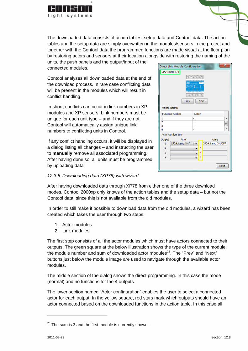
2011-08-23 section 12.8
The downloaded data consists of action tables, setup data and Contool data. The action
tables and the setup data are simply overwritten in the modules/sensors in the project and
together with the Contool data the programmed functions are made visual at the floor plan
by restoring actors and sensors at their location alongside with restoring the naming of the
units, the push panels and the output/input of the
connected modules.
Contool analyses all downloaded data at the end of
the download process. In rare case conflicting data
will be present in the modules which will result in
conflict handling.
In short, conflicts can occur in link numbers in XP
modules and XP sensors. Link numbers must be
unique for each unit type – and if they are not,
Contool will automatically assign unique link
numbers to conflicting units in Contool.
If any conflict handling occurs, it will be displayed in
a dialog listing all changes – and instructing the user
to manually remove all associated programming.
After having done so, all units must be programmed
by uploading data.
12.3.5 Downloading data (XP78) with wizard
After having downloaded data through XP78 from either one of the three download
modes, Contool 2000xp only knows of the action tables and the setup data – but not the
Contool data, since this is not available from the old modules.
In order to still make it possible to download data from the old modules, a wizard has been
created which takes the user through two steps:
1. Actor modules
2. Link modules
The first step consists of all the actor modules which must have actors connected to their
outputs. The green square at the below illustration shows the type of the current module,
the module number and sum of downloaded actor modules25. The “Prev” and “Next”
buttons just below the module image are used to navigate through the available actor
modules.
The middle section of the dialog shows the direct programming. In this case the mode
(normal) and no functions for the 4 outputs.
The lower section named “Actor configuration” enables the user to select a connected
actor for each output. In the yellow square, red stars mark which outputs should have an
actor connected based on the downloaded functions in the action table. In this case all
25 The sum is 3 and the first module is currently shown.

2011-08-23 section 12.9
four outputs need an actor and the first output has already had a “CP24, Lamp on/off”
connected. At the right column the actor can be name. By default it is name the same as
the actor type. Remember to press enter to exit and save the name when renaming.
When all actor modules have had the actors connected to all “red star marked” outputs,
press the Next button at the bottom right corner to go to the second step of the wizard.
The second step of the wizard deals with the link modules26. Just like the first step it
shows the type, link number and amount in the top left corner.
The “Prev” and “Next” buttons are used to navigate through the modules and below is the
direct programming.
The bottom left corner (marked in a green square) holds the eight inputs and their
functions. A red number indicates that this input is not yet connected with a push panel.
The part marked in a yellow square holds all available sensor types at the right, and
available sensor in the project at the left. The marked sensor is shown at the bottom right
corner.
26 CP20/XP20, CP/XP70A-D

2011-08-23 section 12.10
Selecting a push panel works just like it does at the floor plan by enabling the text fields –
but also the option to select which channel from the left side to connect to the selected
push panel (marked in a red square).
Connect all inputs from all link modules to push panels like described above before
pressing the “Finish button”. Doing so will close the wizard and place all new actors on the
floor plan to the left and all new sensors to the right. The actors will be organized in the
order their connected modules are placed at the fuse box (one row per module) and
subsequently by which output they are connected (first output to the far left, last output to
the far right).

2011-08-23 section 13.1
13 Quotation A quotation module is available in the application to generate quotations, unit lists and
simple invoices.
A toolbar is placed at the top of the quotation tab with controls related to the current
quotation (marked in a red square) and controls related to templates (marked in a yellow
square), which will be described in details later on. Underneath this toolbar are two inline
tabs: “Quotation text” and “Unit list management”.
13.1 Quotation (and template)
The inline tab “Quotation text” holds a series of editable text snippets stored in templates.
The template is selected in the yellow square, which also holds icons to “save/save as…”
and “delete” the currently selected template.
The text of the template is editable, but the layout is fixed. In order to see the layout, press
the “Print preview” icon located in the red square. Doing so will open the following dialog
which enables you to select the documents you want to have displayed. The “Unit list” and
“Invoice” part will be described in their own sections later on.
The unit list (marked in a green square) is placed in the middle of the quotation and will be
described in the following section.
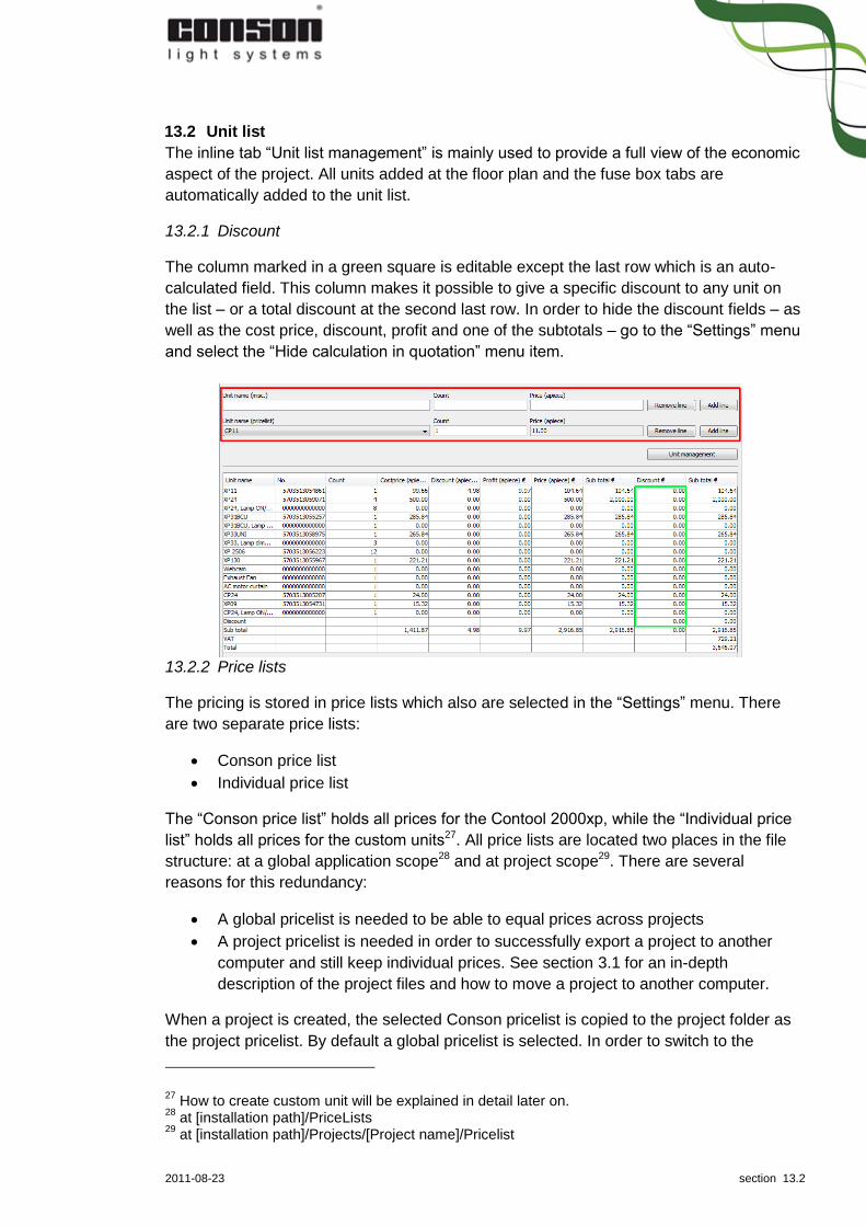
2011-08-23 section 13.2
13.2 Unit list
The inline tab “Unit list management” is mainly used to provide a full view of the economic
aspect of the project. All units added at the floor plan and the fuse box tabs are
automatically added to the unit list.
13.2.1 Discount
The column marked in a green square is editable except the last row which is an auto-
calculated field. This column makes it possible to give a specific discount to any unit on
the list – or a total discount at the second last row. In order to hide the discount fields – as
well as the cost price, discount, profit and one of the subtotals – go to the “Settings” menu
and select the “Hide calculation in quotation” menu item.
13.2.2 Price lists
The pricing is stored in price lists which also are selected in the “Settings” menu. There
are two separate price lists:
Conson price list
Individual price list
The “Conson price list” holds all prices for the Contool 2000xp, while the “Individual price
list” holds all prices for the custom units27. All price lists are located two places in the file
structure: at a global application scope28 and at project scope29. There are several
reasons for this redundancy:
A global pricelist is needed to be able to equal prices across projects
A project pricelist is needed in order to successfully export a project to another
computer and still keep individual prices. See section 3.1 for an in-depth
description of the project files and how to move a project to another computer.
When a project is created, the selected Conson pricelist is copied to the project folder as
the project pricelist. By default a global pricelist is selected. In order to switch to the
27 How to create custom unit will be explained in detail later on.
28 at [installation path]/PriceLists
29 at [installation path]/Projects/[Project name]/Pricelist

2011-08-23 section 13.3
project price list go to the “Settings” menu and select the project pricelist which is marked
with a dark background colour.
13.2.3 Adding and removing units to the quotation
As stated earlier all units added through the floor plan and fuse box tabs are automatically
added to the quotation. Besides adding and removing units through these tabs, it is also
possible to add units directly to the quotation.
In order to remove placed units from the unit list, go to the “Floor plan” tab in design state
and use the arrow controls underneath the top unit list table to remove/un-remove units
from the quotation.
In order to add further units to the quotation go back to the “Quotations” tab and the inline
tab “Unit list management” and use the controls in the upper part (marked in a red
square). The top row makes it possible to enter any text, while the bottom row makes it
possible through a drop down list to select any unit found in Contool 2000xp – as well as
selecting custom units. The built-in Contool 2000xp units are located at the top of the list
while the custom units are located at the bottom. A dotted line in drop down list separates
the two.
But notice that all manually added units only appear in the quotation and these units are
not available for programming. Furthermore notice that all manually added units are kept
at the bottom of the quotation. Even if an automatically added XP11 is present in the
quotation, a manually added XP11 will still be kept in its own record at the bottom.
As shown in section 13.1 it is possible to print the unit list, which will respect the
hide/unhide calculation setting.
13.2.4 Managing units
The “Unit management” button
at the right opens the dialog
below. The upper part marked in
a green square updates the VAT
and currency symbol of both the
Conson pricelist as well as the
Individual pricelist.
The lower part consists of two
inline tabs which update the
Conson pricelist and Individual
pricelist, respectively. The
controls at the lower part marked
in a red square only interacts
with the pricelist on the selected
tab.
The “Modify all” button opens a
dialog with the option to change
the discount and profit percentage for all units (but still only on the selected tab).

2011-08-23 section 13.4
Pressing the “Copy price list” button, will open “save as… like” dialog and the new pricelist
will automatically be selected. In order to copy both pricelists, this action must be
performed on both tabs.
13.3 Invoice
Finally the quotation part of Contool 2000xp is able to print out a simple invoice as shown
in section 13.1. The layout is basically identical to the unit list except for “invoice number”
and “terms of payment” which are filled out by the user prior to creating the print.

2011-08-23 section 14.1
14 Documentation Documentation is automatically generated from the data present in the Fuse box and the
Floor plans tab. The documentation is divided in five reports which can be toggled on/off
at the action panel to the left.
The documentation is updated each time the
Documentation tab is selected, or a report is toggled
on/off.
14.1 Floor plan report
The floor plan report consists of a screen dump of
each floor plan followed by a list of the sensors and
actors as well as a list of the associated fuse boxes.
14.2 Fuse box report
The fuse box report consists of a graphical overview of the modules present on each fuse
box and their placement.
Underneath the graphical overview is a textual overview with all the modules listed in the
same order as graphical overview. Each module is listed with its type, coordinates, serial
number and a list of the units connected with it’s in- and outputs.
14.3 Sensor report
The sensor report lists all sensors. It shows which address30 each input transmits and a
detailed list of the content of each associated function collection.
14.4 Actor report
The actors report lists all actors. It shows its connected module and the sensors affecting
the actor as well as detailed information about which function are setup for each actor.
14.5 Function collection report
The function collection report lists all functions which are grouped by the address by which
they are triggered. This is referred to as a function collection. Each is listed with details
regarding the address, complete content of the function collection, which sensors
triggering it and which actors are affected by it.
30 by link and channel number

2011-08-23 section 15.1
15 Timers Timers can be created to trigger events at a certain point in time. Timers operate on top of
programmed functionality from the floor plan. A simply way to explain the timer module is
to think of it a pressing a push panel at a pre-defined (and perhaps recurring) point in
time.
The timers dialog is shown below where you will notice that it consists of four sections
explained below in detail.
15.1 Timer description
A short description of the timer function displayed at the list (underneath the dialog)
15.2 Timer action and time trigger
Used to specify the time of day when the timer should be executed and to select which
action to trigger. The action is pointed out by selecting a floor plan, a sensor on the floor
plan, a push panel on the sensor and finally whether to push, release or toggle31 the
button.
15.3 Repeat
If you are familiar with the calendar function in Outlook, you should find it easy to use,
since the functionality is displayed in a similar manner. Basically each tab offers you
functionality to repeat the timer on a daily, weekly, monthly or yearly basis.
31 push followed by release

2011-08-23 section 15.2
15.4 Timer repetition settings
This part should also look familiar to user of the calendar in Outlook. This section lets you
select the start date of the timer as well as the end date, if the timer is recurring.

2011-08-23 section 16.1
16 Web service In order to take advantage of the web service in Contool 2000xp, you must have access to
a web server and the following description rests on the assumption that you have such
access and possess basic knowledge on how to operate a web server.
Contool 2000xp contains a Web service in html and wap format. Both of these offer an
interface to operate the functions programmed through Contool 2000xp. The wap format
is pure text based, while the html version contains both text and images. Notice that the
web service is fully functional but it is currently limited to only display Sesam push buttons.
16.1 Setting up the Web service
The following description is a “generic” description which does not deal with differences in
operating system nor network hardware. The image below illustrates a setup similar to the
example in the following section.
Important: Both the wap and the www/html setup need file permission to write and modify
files and subfolders at the “file server path”.
16.1.1 External access

2011-08-23 section 16.2
Which IP/host name to enter in this section depends upon how “remotely” it must be
possible to access Contool 2000xp?
1. If Contool 2000xp and web server are installed on the same computer as the
access is needed: “127.0.0.1” or “localhost” is the right choice. This is rarely the
case but it is sufficient for demo purposed
2. If Contool 2000xp must be accessed from a computer running on the same LAN:
the IP address of the network adapter found on the computer running Contool
2000xp is the right choice32.
3. If Contool 2000xp must be accessed from a computer running outside the LAN:
the IP address must be the global IP of the LAN on which Contool 2000xp is
installed – or a hostname pointed to the global IP of the LAN. Furthermore the
router on the LAN must forward the traffic on the entered port (default 9090) using
NAT to the IP address of the network adapter found on the computer running
2000xp.
16.1.2 Wap setup
In order to enable Wap support, start by check the box “Mobile phone light control service
enabled”.
The “server URL” is simply the URL to access your web server – e.g.
mydomain.com/conson/wap.
The “file server path” must be specified with a drive letter – e.g.
C:/inetpub/wwwroot/conson/wap/. Consequently it is far the easiest to have the web
server installed on the same computer as Contool 2000xp but if this is inconvenient there
are workarounds:
Third party tools can map an ftp connection to a remote server as a drive letter
Third party tools can auto-copy files from a local folder to a remote server
The “update” button generates new wap files on the specified “server file path”. And
checking “auto upload” makes Contool 2000xp handle this operation automatically
whenever events occurs which facilitates changes in these files.
The “select sensors” buttons makes it possible to select which sensors should be included
in the wap functionality. By default any new sensor is not part of this functionality.
16.1.3 Html setup
This section is nearly identical to the wap setup and to avoid confusion only the
differences will be pointed out.
The “server URL” is still the URL to access your web server – e.g.
mydomain.com/conson/www
32 On Windows this can be found by running a command prompt and typing “ipconfig” followed by
Enter

2011-08-23 section 16.3
The “server file path” should be different from the wap setup. It could for instance be
C:/inetpub/wwwroot/conson/www/.
When updating the www files a few static images are copied to “server file path”/images
folder (only on first update) and an image of the current floor plans are dynamically
created and copied (on each update) to “server file path”/images/floorplans. The html file
contains a WebClip Bookmark which can be used to easily create a link on the home
screen of a iPhone/iPad.