user manual gl2000 series - vectorvector informatik gmbh has iso 9001:2008 certification. the iso...
TRANSCRIPT

User Manual
GL2000 Series
Version 2.5 English

Imprint Vector Informatik GmbH Ingersheimer Straße 24 D-70499 Stuttgart Vector reserves the right to modify any information and/or data in this user documentation without notice. This documentation nor any of its parts may be reproduced in any form or by any means without the prior written consent of Vector. To the maximum extent permitted under law, all technical data, texts, graphics, images and their design are protected by copyright law, various international treaties and other applicable law. Any unauthorized use may violate copyright and other applicable laws or regulations. © Copyright 2018, Vector Informatik GmbH. Printed in Germany. All rights reserved.
User Manual GL2000 Series Table of Contents
© Vector Informatik GmbH Version 2.5 - I -
Table of Contents
1 Introduction 3
1.1 About this User Manual 4 1.1.1 Certification 5 1.1.2 Warranty 5 1.1.3 Support 5 1.1.4 Trademarks 5
1.2 Important Notes 6 1.2.1 Safety Instructions and Hazard Warnings 6
1.2.1.1 Proper Use and Intended Purpose 6 1.2.1.2 Hazards 6 1.2.1.3 Disclaimer 7
1.2.2 SEGGER emFile Module 7
2 GL2000 – Data Logger 9
2.1 General Information 10 2.2 Features 11
2.2.1 Connectors 11 2.2.2 SD/SDHC Memory Card 14 2.2.3 Serial Number 16 2.2.4 LED Display 17 2.2.5 Digital Input/Output 18 2.2.6 Analog Inputs 19 2.2.7 Serial Interface 19 2.2.8 Real-Time Clock with Battery 19 2.2.9 Beep 21 2.2.10 Wake-up / Sleep 21 2.2.11 CCP/XCP 22 2.2.12 Diagnostics 23
2.3 Operating Modes 23 2.4 CAN and LIN 24
2.4.1 CAN/CAN FD 24 2.4.2 CAN/CAN FD Piggybacks 24 2.4.3 LIN 27
2.5 GPS Mouse 27 2.6 Ethernet 28 2.7 3G (UMTS) 28 2.8 Technical Data 29 2.9 Included with Delivery 30 2.10 Accessories 30
3 Installation Configuration Programs 31
3.1 Overview 32 3.2 Installation Vector Logger Configurator 32
3.2.1 Requirements 32 3.2.2 Setup 33 3.2.3 Overview 33 3.2.4 Quick Start 34
3.3 Installation G.i.N. Configuration Program 35

User Manual GL2000 Series Table of Contents
© Vector Informatik GmbH Version 2.5 - II -
3.3.1 Requirements 35 3.3.2 Setup 35 3.3.3 Overview 36 3.3.4 Quick Start 37
4 Index 39

User Manual GL2000 Series Introduction
© Vector Informatik GmbH Version 2.5 - 3 -
1 Introduction
In this chapter you find the following information:
1.1 About this User Manual page 4 Certification Warranty Support Trademarks
1.2 Important Notes page 6 Safety Instructions and Hazard Warnings SEGGER emFile Module

User Manual GL2000 Series Introduction
© Vector Informatik GmbH Version 2.5 - 4 -
1.1 About this User Manual
To find information quickly
The user manual provides you the following access helps: > At the beginning of each chapter you will find a summary of the contents, > In the header you can see the current chapter and section, > In the footer you can see to which version the user manual replies, > At the end of the user manual you will find an index.
Conventions In the two following charts you will find the conventions used in the user manual regarding utilized spellings and symbols.
Style Utilization bold Blocks, surface elements, window- and dialog names of the
software. Accentuation of warnings and advices. [OK] Push buttons in brackets File | Save Notation for menus and menu entries
Windows Legally protected proper names and side notes. Source code File name and source code. Hyperlink Hyperlinks and references. <STRG>+<S> Notation for shortcuts. Symbol Utilization
Here you can find additional information and hints that eases the work with the loggers.
This symbol calls your attention to warnings.
Here you can find additional information.
Here is an example that has been prepared for you.
Step-by-step instructions provide assistance at these points.
Instructions on editing files are found at these points.
This symbol warns you not to edit the specified file.

User Manual GL2000 Series Introduction
© Vector Informatik GmbH Version 2.5 - 5 -
1.1.1 Certification
Certified Quality Management System
Vector Informatik GmbH has ISO 9001:2008 certification. The ISO standard is a globally recognized standard.
1.1.2 Warranty
Restriction of warranty
We reserve the right to modify the contents of the documentation or the software without notice. Vector disclaims all liabilities for the completeness or correctness of the contents and for damages which may result from the use of this documentation.
1.1.3 Support
You need support? You can get through to our hotline at the phone number
+49 711 80670-200
or you write an email to [email protected].
1.1.4 Trademarks
Protected trademarks
All brand names in this documentation are either registered or non registered trademarks of their respective owners.

User Manual GL2000 Series Introduction
© Vector Informatik GmbH Version 2.5 - 6 -
1.2 Important Notes
1.2.1 Safety Instructions and Hazard Warnings
Caution: In order to avoid personal injuries and damage to property, you have to read and understand the following safety instructions and hazard warnings prior to installation and use of the loggers of this G2000 family. Keep this documentation (manual) always near the logger.
1.2.1.1 Proper Use and Intended Purpose
Caution: The loggers are measuring devices which are mainly used in the automotive and commercial vehicles industries. The loggers are designed for gathering and recording data of the bus communication, for analyzing and possibly controlling electronic control units. This includes, inter alia, bus systems like CAN and LIN.
The loggers may only be operated in a closed state. In particular, printed circuits must not be visible. The loggers may only be operated according to the instructions and descriptions of this manual. Only suitable accessories should be used, such as the original Vector accessories or accessories approved by Vector.
The loggers are exclusively designed for use by skilled personnel as its operation may result in serious personal injuries and damage to property. Therefore, only those persons may operate the loggers who (i) have understood the possible effects of the actions which may be caused by the loggers; (ii) are specifically trained in the handling with the loggers, bus systems and the system intended to be influenced; and (iii) have sufficient experience in using the loggers safely.
The logger specific information can be acquired via the specific manuals as well as from the Vector KnowledgeBase at www.vector.com. Please consult the Vector KnowledgeBase for updated information prior to the operation of the loggers. The knowledge necessary for the bus systems used, can be acquired in workshops and internal or external seminars offered by Vector.
1.2.1.2 Hazards
Caution: The loggers may control and/or otherwise influence the behavior of electronic control units. Serious hazards for life, body and property may arise, in particular, without limitation, by interventions in safety relevant systems (e.g. by deactivating or otherwise manipulating the engine management, steering, airbag and/or braking system) and/or if the loggers are operated in public areas (e.g. public traffic, airspace). Therefore, you must always ensure that the loggers are used in a safe manner. This includes, inter alia, the ability to put the system in which the loggers are used into a safe state at any time (e.g. by „emergency shutdown“), in particular, without limitation, in the event of errors or hazards.
Comply with all safety standards and public regulations which are relevant for the operation of the system. Before you operate the system in public areas, it should be tested on a site which is not accessible to the public and specifically prepared for performing test drives in order to reduce hazards.
User Manual GL2000 Series Introduction
© Vector Informatik GmbH Version 2.5 - 7 -
1.2.1.3 Disclaimer
Caution: Claims based on defects and liability claims against Vector are excluded to the extent damages or errors are caused by improper use of the loggers or use not according to its intended purpose. The same applies to damages or errors arising from insufficient training or lack of experience of personnel using the loggers.
1.2.2 SEGGER emFile Module
Note: The firmware of the GL2000 series contains the copyright protected emFile module of SEGGER Microcontroller GmbH & Co. KG.
It should be noted that the Licensing Terms of the Licensor expressly prohibit the use of the SEGGER emFile module in weapons/weapons systems and/or their deployment in same. A “weapons system” is to be understood as meaning, in particular, a system whose primary or material purpose is to injure, incapacitate or kill a person or an opponent, or to destroy or damage the property of a person or an opponent, or to threaten a person or an opponent, irrespective of whether the weapon or the weapon system can be used to attack, defend, threaten or protect.


User Manual GL2000 Series GL2000 – Data Logger
© Vector Informatik GmbH Version 2.5 - 9 -
2 GL2000 – Data Logger
In this chapter you find the following information:
2.1 General Information page 10
2.2 Features page 11 Connectors SD/SDHC Memory Card Serial Number LED Display Digital Input/Output Analog Inputs Serial Interface Real-Time Clock with Battery Beep Wake-up / Sleep CCP/XCP Diagnostics
2.3 Operating Modes page 23
2.4 CAN and LIN page 24 CAN/CAN FD CAN/CAN FD Piggybacks LIN
2.5 GPS Mouse page 27
2.6 Ethernet page 28
2.7 3G (UMTS) page 28
2.8 Technical Data page 29
2.9 Included with Delivery page 30
2.10 Accessories page 30
User Manual GL2000 Series GL2000 – Data Logger
© Vector Informatik GmbH Version 2.5 - 10 -
2.1 General Information
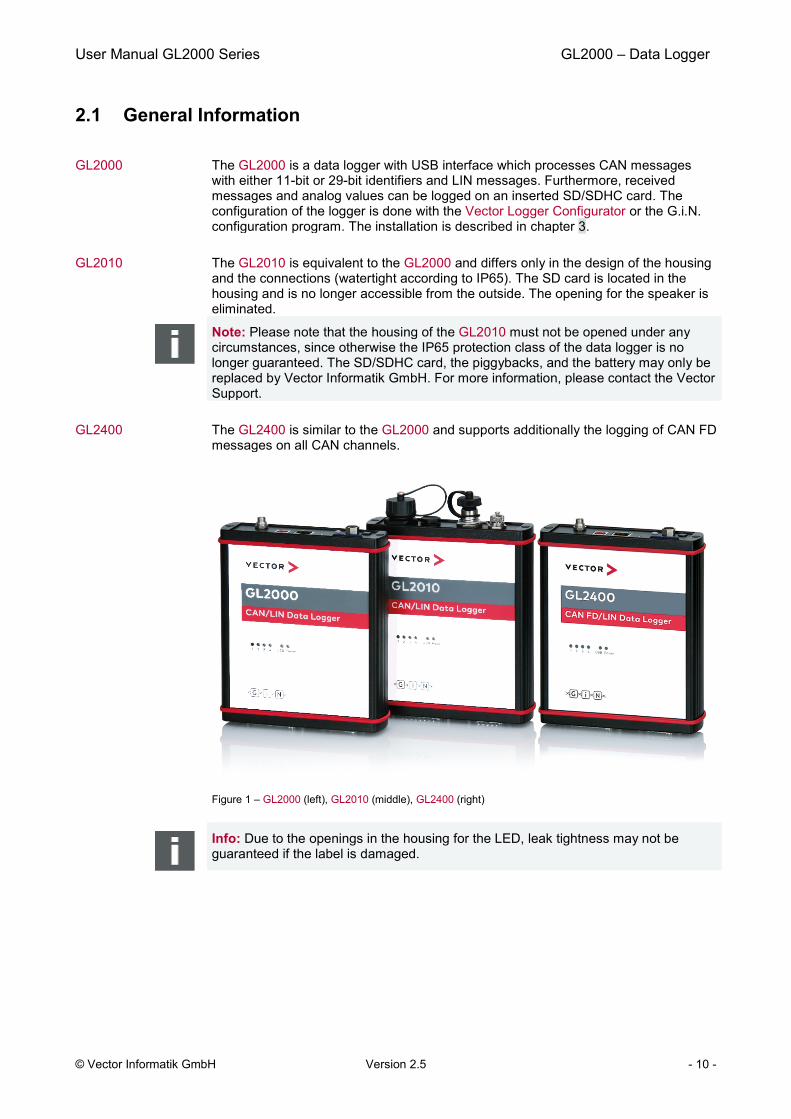
GL2000 The GL2000 is a data logger with USB interface which processes CAN messages with either 11-bit or 29-bit identifiers and LIN messages. Furthermore, received messages and analog values can be logged on an inserted SD/SDHC card. The configuration of the logger is done with the Vector Logger Configurator or the G.i.N. configuration program. The installation is described in chapter 3.
GL2010 The GL2010 is equivalent to the GL2000 and differs only in the design of the housing and the connections (watertight according to IP65). The SD card is located in the housing and is no longer accessible from the outside. The opening for the speaker is eliminated.
Note: Please note that the housing of the GL2010 must not be opened under any circumstances, since otherwise the IP65 protection class of the data logger is no longer guaranteed. The SD/SDHC card, the piggybacks, and the battery may only be replaced by Vector Informatik GmbH. For more information, please contact the Vector Support.
GL2400 The GL2400 is similar to the GL2000 and supports additionally the logging of CAN FD messages on all CAN channels.
Figure 1 – GL2000 (left), GL2010 (middle), GL2400 (right)
Info: Due to the openings in the housing for the LED, leak tightness may not be guaranteed if the label is damaged.

User Manual GL2000 Series GL2000 – Data Logger
© Vector Informatik GmbH Version 2.5 - 11 -
2.2 Features
2.2.1 Connectors
General information The loggers have the following connectors: > USB connector: data transfer between PC and logger > DSUB25 connector Vehicle containing:
4 CAN channels 2 LIN channels 2 digital inputs/outputs 4 analog inputs Battery and ground Ignition
> DSUB15 connector Extension containing: 2 digital inputs/outputs GPS module Switch box External supply for galvanically isolated piggybacks
> SD/SDHC card slot (externally accessible) > AUX connection for logger accessories > Event connector for switch box E2T2L (GL2000 V2.0 and GL2400 only)
DSUB25 pin assignment
The pins of the Vehicle connector have the following meaning. The colors refer to the included connection cable Vehicle.
Pin Assignment Color Pin Assignment Color 1 Battery (VCC) white 14 CAN3 Low white/blue 2 RS232 Rx white/green 15 CAN1 High yellow 3 RS232 Tx brown/pink 16 CAN1 Low green 4 GND brown 17 CAN4 High white/gray 5 Battery (VCC) white/black 18 CAN4 Low white/pink 6 I/O 1 white/yellow 19 CAN2 High grey 7 GND brown/red 20 Wake/KL15 black 8 I/O 2 brown/yellow 21 CAN2 Low pink 9 Analog In 1 grey/pink 22 GND brown/blue 10 Analog In 2 red/blue 23 LIN 1 lilac 11 Analog In 3 blue 24 LIN 2 red 12 Analog In 4 brown/green 25 K-Line brown /gray 13 CAN3 High white/red
The three GND pins are connected together internally and have the same potential as the power supply ground.

User Manual GL2000 Series GL2000 – Data Logger
© Vector Informatik GmbH Version 2.5 - 12 -
Caution: It is recommended to connect the logger to the same voltage supply (e.g. battery of the vehicle) as the vehicle or test equipment, respectively.
If two different voltage supplies are used for the logger and the test equipment, the ground (GND) pins of the two voltage supplies must be connected.
Connection cable Vehicle
In the delivery a connection cable for the Vehicle connector is included with the following connections.
CAN1 DSUB9 with black cap CAN2 DSUB9 with red cap LIN1 DSUB9 with yellow cap Vbatt/KL30 red pin plug GND black pin plug Wake/KL15 red pin plug All other wires have open wire ends. If these wires are not used, it is recommended to
terminate them. This prevents short circuits between the open wires. At the same time the EMC properties are improved.
Note: The connecting cable does not conform to IP65.
DSUB15 pin assignment
The pins of the Extension connector have the following meaning.
Pin Assignment Pin Assignment 1 CAN3_Vbatt 9 CAN3_GND 2 CAN4_Vbatt 10 CAN4_GND 3 LIN1_Vbatt (24V) 11 I/O 4 4 LIN2_Vbatt (24V) 12 V+ (switch box) 5 I/O 3 13 T1 (switch box) 6 V+ (GPS) 14 T2 (switch box) 7 Rx (GPS) 15 GND 8 Tx (GPS)
The four GND pins on the connectors Vehicle and Extension are connected together internally and have the same potential as the power supply ground.
Connection cable Extension (not for GL2000 V2.0 and GL2400)
In the delivery a connection cable for the Extension connector is included.
The delivered switch box E2T2L is connected to the 5-pin Binder connector. The PS2 connector is provided for an optional serial GPS mouse. The contacts for further pins are loosely added.
You can find further information about the GPS mouse in chapter 2.5.
User Manual GL2000 Series GL2000 – Data Logger
© Vector Informatik GmbH Version 2.5 - 13 -
Note: The connecting cable does not conform to IP65.
Event connection (GL2000 V2.0 and GL2400 only)
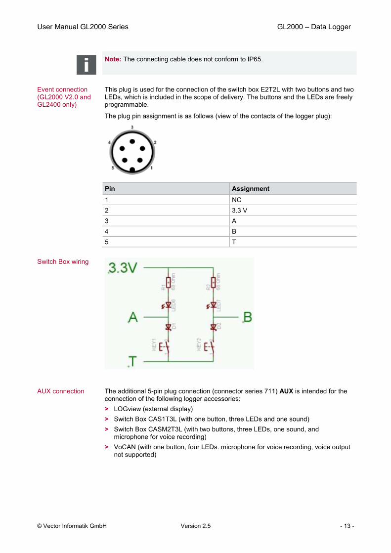
This plug is used for the connection of the switch box E2T2L with two buttons and two LEDs, which is included in the scope of delivery. The buttons and the LEDs are freely programmable.
The plug pin assignment is as follows (view of the contacts of the logger plug):
Pin Assignment 1 NC 2 3.3 V 3 A 4 B 5 T
Switch Box wiring
AUX connection The additional 5-pin plug connection (connector series 711) AUX is intended for the connection of the following logger accessories:
> LOGview (external display) > Switch Box CAS1T3L (with one button, three LEDs and one sound) > Switch Box CASM2T3L (with two buttons, three LEDs, one sound, and
microphone for voice recording) > VoCAN (with one button, four LEDs. microphone for voice recording, voice output
not supported)

User Manual GL2000 Series GL2000 – Data Logger
© Vector Informatik GmbH Version 2.5 - 14 -
The plug pin assignment is as follows (view of the contacts of the logger socket): Pin Assignment 1 +5V 2 Ground 3 CAN high 4 CAN low 5 Vbatt
The AUX connection is wired to CAN5 internally. For this reason, this channel is always equipped with a high-speed transceiver without wake-up capability and can no longer be used freely if an AUX connection is used.
2.2.2 SD/SDHC Memory Card
SD and SDHC cards The logger supports industrial grade SD cards up to 2 GB and industrial grade SDHC cards.
For the proper use only the industrial grade cards released by Vector may be used. These cards are listed below. Please note that cards may be listed which are no longer available.
Note for formatting: The memory cards have to be FAT32 formatted. For optimum speed we recommend FAT32 formatting with the possible maximum cluster size.
Recommended SD cards
The following SD cards with industrial grade are recommended, see also section 2.8: > Xmore industrial 2 GB (SD-2G0-XIWE21, SD-2G0-XIE82) > Cactus Industrial Grade 2 GB (KS 2GRI-800), some higher start-up time
Recommended SDHC cards
The following SDHC cards with industrial grade are recommended, see also section 2.8: > Xmore industrial 8 GB (SD-8G0-XIE23, SD-8G0-XIE82) > Xmore industrial 16 GB (SD-16G-XIE23, SD-16G-XIE82) > Xmore industrial 32 GB (SD032GXQI8C016Z) > Cactus Industrial Grade 4 GB (KS 4GRI-800) > Cactus Industrial Grade 8 GB (KS 8GRI-800) > SanDisk Industrial XT 32 GB (SDSDAF-032G-XI SD)
GL2000: Inserting and removing SD card
The GL2000 has a push-and-pull card holder for inserting and removing the SD card. To insert the memory card, push it in until the locking mechanism engages securely. To remove the memory card, push it slightly into the card holder until it unlocks. Now, release the memory card. The card moves from its original position and can now be removed.
Do not pull the SD card from the card holder forcefully, since this could cause mechanical damage!
User Manual GL2000 Series GL2000 – Data Logger
© Vector Informatik GmbH Version 2.5 - 15 -
GL2000 V2.0 and GL2400: Remove SD card with shutdown button
GL2000 V2.0 and GL2400 have a shutdown button on the top cover. It interrupts an active logging in order to remove or exchange the SD card. Required firmware for GL2000 V2.0: Firmware V1.38 or higher (available from Vector Logger Configurator 2.5 SP4).
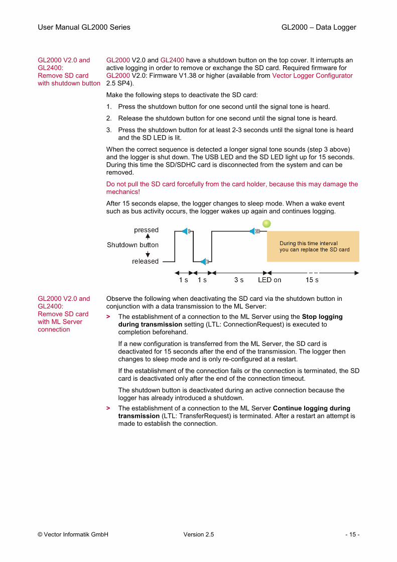
Make the following steps to deactivate the SD card:
1. Press the shutdown button for one second until the signal tone is heard.
2. Release the shutdown button for one second until the signal tone is heard.
3. Press the shutdown button for at least 2-3 seconds until the signal tone is heard and the SD LED is lit.
When the correct sequence is detected a longer signal tone sounds (step 3 above) and the logger is shut down. The USB LED and the SD LED light up for 15 seconds. During this time the SD/SDHC card is disconnected from the system and can be removed.
Do not pull the SD card forcefully from the card holder, because this may damage the mechanics!
After 15 seconds elapse, the logger changes to sleep mode. When a wake event such as bus activity occurs, the logger wakes up again and continues logging.
GL2000 V2.0 and GL2400: Remove SD card with ML Server connection
Observe the following when deactivating the SD card via the shutdown button in conjunction with a data transmission to the ML Server: > The establishment of a connection to the ML Server using the Stop logging
during transmission setting (LTL: ConnectionRequest) is executed to completion beforehand.
If a new configuration is transferred from the ML Server, the SD card is deactivated for 15 seconds after the end of the transmission. The logger then changes to sleep mode and is only re-configured at a restart.
If the establishment of the connection fails or the connection is terminated, the SD card is deactivated only after the end of the connection timeout.
The shutdown button is deactivated during an active connection because the logger has already introduced a shutdown.
> The establishment of a connection to the ML Server Continue logging during transmission (LTL: TransferRequest) is terminated. After a restart an attempt is made to establish the connection.

User Manual GL2000 Series GL2000 – Data Logger
© Vector Informatik GmbH Version 2.5 - 16 -
GL2000 V1.0: Remove SD card with event buttons
The GL2000 V1.0 has no shutdown button on the top cover. Instead you can use the two buttons on the delivered switch box E2T2L to interrupt an active logging in order to remove or exchange the SD card.
Therefore, the logger must contain the firmware V1.40 or higher (available from Vector Logger Configurator 2.6 SP3).
Make the following step to deactivate the SD card: > Press the two buttons on the switch box E2T2L simultaneously for five seconds.
After each second a signal tone is heard.
Afterwards the GL2000 V1.0 is shut down and LED1 to LED4 are off. The USB LED lights up for 15 seconds. During this time the SD/SDHC card is disconnected from the system and can be removed.
Do not pull the SD card forcefully from the card holder, because this may damage the mechanics!
After 15 seconds elapse, the logger changes to sleep mode. When a wake event such as bus activity occurs, the logger wakes up again and continues logging.
GL2010: SD card The SD card is already contained in the housing of the GL2010 and cannot be removed or replaced.
Note: Please note that the housing of the GL2010 must not be opened under any circumstances, since otherwise the IP65 protection class of the data logger is no longer guaranteed. The SD/SDHC card may only be replaced by Vector Informatik GmbH. For more information, please contact the Vector Support.
Data transfer The logged data can be downloaded with a configuration program from the SD/SDHC card in the logger or in a card reader. Alternatively logging files can be copied to the PC via the Windows Explorer. On the PC the logging files can be converted.
2.2.3 Serial Number
Serial number The serial number is stored in the logger and is copied to the SD card after download of the configuration and start in logging mode.
The configuration program reads out the serial number of the logger in the configuration mode. The serial number is displayed correctly, if an SD card is inserted and the logger was at least one time in the logging mode with this SD card. If this SD card is inserted in another logger and the logger is not started in logging mode afterwards, the serial number of the first logger will be displayed in the configuration program.
User Manual GL2000 Series GL2000 – Data Logger
© Vector Informatik GmbH Version 2.5 - 17 -
2.2.4 LED Display
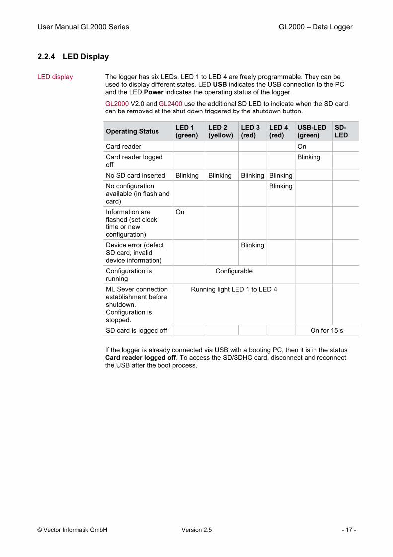
LED display The logger has six LEDs. LED 1 to LED 4 are freely programmable. They can be used to display different states. LED USB indicates the USB connection to the PC and the LED Power indicates the operating status of the logger.
GL2000 V2.0 and GL2400 use the additional SD LED to indicate when the SD card can be removed at the shut down triggered by the shutdown button.
Operating Status LED 1 (green)
LED 2 (yellow)
LED 3 (red)
LED 4 (red)
USB-LED (green)
SD-LED
Card reader On Card reader logged
off Blinking
No SD card inserted Blinking Blinking Blinking Blinking No configuration
available (in flash and card)
Blinking
Information are flashed (set clock time or new configuration)
On
Device error (defect SD card, invalid device information)
Blinking
Configuration is running
Configurable
ML Sever connection establishment before shutdown. Configuration is stopped.
Running light LED 1 to LED 4
SD card is logged off On for 15 s
If the logger is already connected via USB with a booting PC, then it is in the status Card reader logged off. To access the SD/SDHC card, disconnect and reconnect the USB after the boot process.

User Manual GL2000 Series GL2000 – Data Logger
© Vector Informatik GmbH Version 2.5 - 18 -
2.2.5 Digital Input/Output
Digital IO The logger supports four pins which can be used either as digital inputs or as digital outputs.
Using as input A digital input can be used e.g. as external trigger.
In unconnected state the digital inputs are set to High (TRUE). After connecting the input with GND the status is set to Low (FALSE).
Technical data
Operating voltage range -0.3 V…36 V Pull-up resistor 10 kΩ to 3.3 V Threshold Low → High 1.9 V Threshold High → Low 0.55 V Sampling rate 1 kHz State unconnected input High (TRUE)
Using as output When used as a digital output, the pin is connected to GND when the output is switched on (so called “low side switch”). To switch a consumer it is necessary to connect it between the pin of the digital output and the battery.
Technical data
Operating voltage range -0.3 V…36 V Current when switched on Max. 500 mA per output Nominal output current
(all channels on) Max. 250 mA* per output
Amount of all digital outputs Max. 1000 mA* Internal resistance
(on resistance) 1 Ω
Circuit time Typ. 1 ms
* Output current depends on external circuit
User Manual GL2000 Series GL2000 – Data Logger
© Vector Informatik GmbH Version 2.5 - 19 -
2.2.6 Analog Inputs
Analog inputs The logger has four independent analog channels which can be configured separately.
Technical data
Voltage range 0 V … 18 V Resolution 10 bit Precision 1 % Sampling rate Max. 1 kHz Type Single-ended to ground, unipolar Input resistance 155.6 kΩ
Reverse-polarity protection -50 V … +50 V -150 V … +150 V (for max. 3 seconds)
Averaging It is possible to average the measured analog inputs over a defined sampling period between 1 kHz and 1 Hz. E.g. for a 1 Hz sampling frequency, the measured values are averaged over the last second. The internal sampling rate is 1 kHz for each channel.
2.2.7 Serial Interface
RS232 The serial interface with the Rx and Tx lines is logging interfaces only. The baudrate of the interfaces can be configured. Received data can be stored on the SD card as CAN messages.
Info: The serial interface cannot be used to download a configuration or upload logging data.
2.2.8 Real-Time Clock with Battery
Real-time clock The loggers have an internal real-time clock, which is battery supplied, and thus continues running even if the logger is disconnected from power supply. The real-time clock inside the logger is required to store the date and time together with the logged data.
The configuration of the clock is done with the configuration program (SD card must be inserted). After setting the real-time clock the logger is switched off.
It is recommended to set the real-time clock before first logging.
Battery The internal battery supplies the real-time clock only. The battery has a typical durability of approximately 5-10 years under the following conditions:
T = +40°C to +80°C for at most 40 hours per week T = -40°C to +40°C in the rest of the time

User Manual GL2000 Series GL2000 – Data Logger
© Vector Informatik GmbH Version 2.5 - 20 -
GL2010/GL2400: Battery
Please note that the housing of the GL2010 must not be opened under any circumstances, since otherwise the IP65 protection class of the data logger is no longer guaranteed.
The battery of GL2010/GL2400 may only be replaced by Vector Informatik GmbH. For more information, please contact the Vector Support.
GL2000: Replacing battery
The battery of the GL2000 can be exchanged after life cycle end.
Notes: > First read the installation instruction completely.> The case has to be opened to exchange the piggybacks.> This must be done very cautiously and carefully.
The battery is exchanged as follows:
1. First remove the two black decorative caps and the screws from the bottom coverof the GL2000. The bottom cover contains the two DSUB connectors.
2. Then, remove the two black decorative caps and the screws from the top cover.Among other things, the top cover contains the USB connector.
3. Carefully remove the bottom cover together with the main board and the topcover completely from the housing.
Note: The circuit board is connected to the AUX connection of the top cover via acable. Therefore, the top cover must be inserted together with the circuit boardfrom the top to the bottom of the housing. Please make sure not to damage thecable.
4. You will find mounting location almost at the center of the main circuit board (seegreen circle in Figure 3).
5. Remove the battery carefully from the mounting location.
6. Insert the replacement battery. Look out for the correct polarity, + must be on top.Please handle the contact spring with care. Do not bend it too much and makesure the spring has contact to the new battery after replacement.
7. Reassemble the unit in reverse order. First insert the top cover into the housingvia the opening at the bottom. Insert the circuit board into the housing afterwardsand make sure that the circuit board has been inserted into the correct guide rail(groove 1). Please be sure that the frame around the LEDs do not snag on thehousing.
8. It should be possible to slide the main board in the housing up to a fewmillimeters from the end without forcing it in. Close the housing by applying lightpressure, and then secure the covers with the appropriate screw fasteners. Thescrews should be secure but not excessively tight.
9. Please also attach the black decorative caps.
Dispose of the removed battery according to the applicable laws (e.g. the Battery Law in Germany).
User Manual GL2000 Series GL2000 – Data Logger
© Vector Informatik GmbH Version 2.5 - 21 -
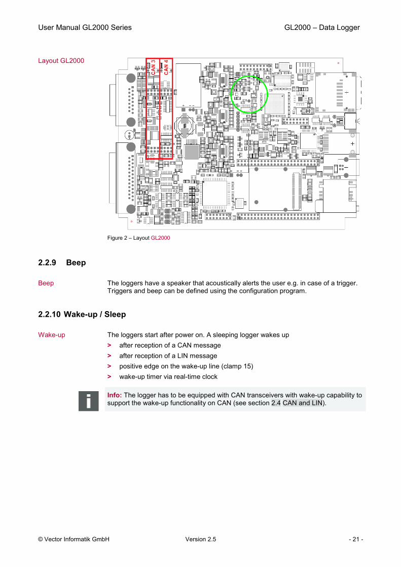
Layout GL2000
Figure 2 – Layout GL2000
2.2.9 Beep
Beep The loggers have a speaker that acoustically alerts the user e.g. in case of a trigger. Triggers and beep can be defined using the configuration program.
2.2.10 Wake-up / Sleep
Wake-up The loggers start after power on. A sleeping logger wakes up > after reception of a CAN message > after reception of a LIN message > positive edge on the wake-up line (clamp 15) > wake-up timer via real-time clock
Info: The logger has to be equipped with CAN transceivers with wake-up capability to support the wake-up functionality on CAN (see section 2.4 CAN and LIN).
User Manual GL2000 Series GL2000 – Data Logger
© Vector Informatik GmbH Version 2.5 - 22 -
Sleep The logger can be configured to go to sleep mode if no CAN and LIN messages are received for a defined time. This time can be configured (max. 18.000 s = 5 hours). The sleep mode needs a very low current consumption of typ. 1 mA.
Fast wake-up from standby mode (GL2000/GL2010)
The loggers can be configured in the configuration program such that they go to standby mode instead of sleep mode. The fast wake-up from standby mode allows the recoding of the very first message waking up the logger. The logger is waken up from standby mode by the same events as from sleep mode. However, with typ. 50 mA the standby mode has a higher current consumption than the sleep mode.
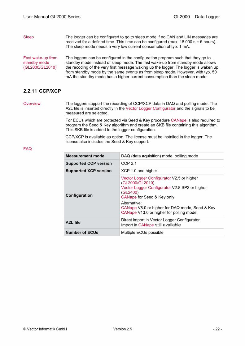
2.2.11 CCP/XCP
Overview The loggers support the recording of CCP/XCP data in DAQ and polling mode. The A2L file is inserted directly in the Vector Logger Configurator and the signals to be measured are selected.
For ECUs which are protected via Seed & Key procedure CANape is also required to program the Seed & Key algorithm and create an SKB file containing this algorithm. This SKB file is added to the logger configuration.
CCP/XCP is available as option. The license must be installed in the logger. The license also includes the Seed & Key support.
FAQ
Measurement mode DAQ (data aquisition) mode, polling mode
Supported CCP version CCP 2.1
Supported XCP version XCP 1.0 and higher
Configuration
Vector Logger Configurator V2.5 or higher (GL2000/GL2010) Vector Logger Configurator V2.8 SP2 or higher (GL2400) CANape for Seed & Key only Alternative: CANape V8.0 or higher for DAQ mode, Seed & Key CANape V13.0 or higher for polling mode
A2L file Direct import in Vector Logger Configurator
Import in CANape still available Number of ECUs Multiple ECUs possible
User Manual GL2000 Series GL2000 – Data Logger
© Vector Informatik GmbH Version 2.5 - 23 -
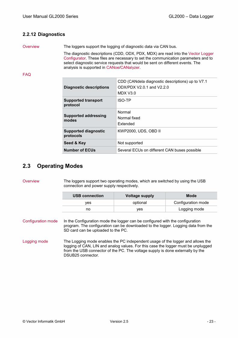
2.2.12 Diagnostics
Overview The loggers support the logging of diagnostic data via CAN bus.
The diagnostic descriptions (CDD, ODX, PDX, MDX) are read into the Vector Logger Configurator. These files are necessary to set the communication parameters and to select diagnostic service requests that would be sent on different events. The analysis is supported in CANoe/CANalyzer.
FAQ
Diagnostic descriptions CDD (CANdela diagnostic descriptions) up to V7.1 ODX/PDX V2.0.1 and V2.2.0 MDX V3.0
Supported transport protocol
ISO-TP
Supported addressing modes
Normal Normal fixed Extended
Supported diagnostic protocols
KWP2000, UDS, OBD II
Seed & Key Not supported Number of ECUs Several ECUs on different CAN buses possible
2.3 Operating Modes
Overview The loggers support two operating modes, which are switched by using the USB connection and power supply respectively.
USB connection Voltage supply Mode yes optional Configuration mode no yes Logging mode
Configuration mode In the Configuration mode the logger can be configured with the configuration program. The configuration can be downloaded to the logger. Logging data from the SD card can be uploaded to the PC.
Logging mode The Logging mode enables the PC independent usage of the logger and allows the logging of CAN, LIN and analog values. For this case the logger must be unplugged from the USB connector of the PC. The voltage supply is done externally by the DSUB25 connector.
User Manual GL2000 Series GL2000 – Data Logger
© Vector Informatik GmbH Version 2.5 - 24 -
2.4 CAN and LIN
2.4.1 CAN/CAN FD
CAN channels GL2000 and GL2010 support four CAN channels. Channel 1 - 2 Permanently occupied by high-speed CAN transceiver TJA1043 Channel 3 - 4 Freely configurable via piggyback PCBs
CAN FD channels GL2400 supports four CAN/CAN FD channels (optionally ISO CAN FD or NON-ISO CAN FD).
Channel 1 - 4 Freely configurable via GLT piggyback PCBs
Wake-up capability The logger can be woken up on the four CAN or CAN FD channels. The channels must be occupied with piggybacks with wake-up capable CAN transceivers if the wake-up will be executed via these channels.
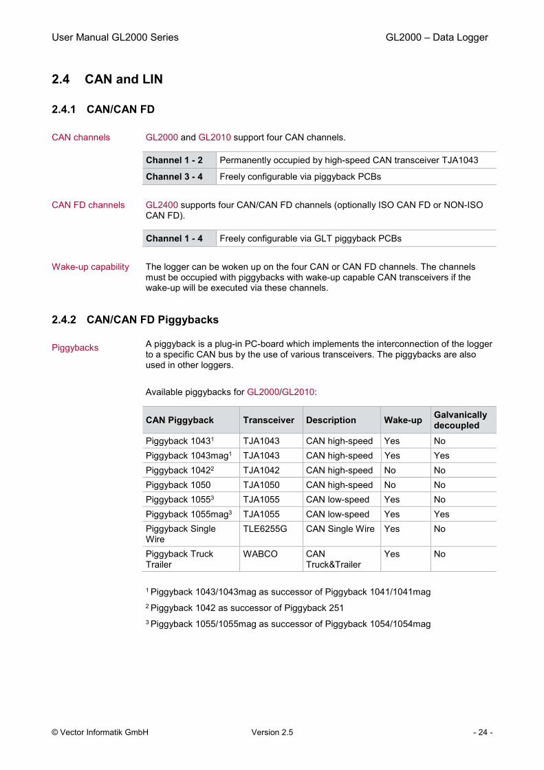
2.4.2 CAN/CAN FD Piggybacks
Piggybacks A piggyback is a plug-in PC-board which implements the interconnection of the logger to a specific CAN bus by the use of various transceivers. The piggybacks are also used in other loggers.
Available piggybacks for GL2000/GL2010:
CAN Piggyback Transceiver Description Wake-up Galvanically decoupled
Piggyback 10431 TJA1043 CAN high-speed Yes No Piggyback 1043mag1 TJA1043 CAN high-speed Yes Yes Piggyback 10422 TJA1042 CAN high-speed No No Piggyback 1050 TJA1050 CAN high-speed No No Piggyback 10553 TJA1055 CAN low-speed Yes No Piggyback 1055mag3 TJA1055 CAN low-speed Yes Yes Piggyback Single
Wire TLE6255G CAN Single Wire Yes No
Piggyback Truck Trailer
WABCO CAN Truck&Trailer
Yes No
1 Piggyback 1043/1043mag as successor of Piggyback 1041/1041mag 2 Piggyback 1042 as successor of Piggyback 251 3 Piggyback 1055/1055mag as successor of Piggyback 1054/1054mag

User Manual GL2000 Series GL2000 – Data Logger
© Vector Informatik GmbH Version 2.5 - 25 -
For the GL2400 GLT piggybacks are required. The following GLT piggybacks are available:
CAN/CAN FD Piggyback Transceiver Description Wake-up Galvanically
decoupled GLT piggyback 1043 TJA1043TK CAN/CAN FD
high-speed Yes No
GLT piggyback 1055 TJA1055 CAN low-speed Yes No
Note: Transceivers with wake-up capability are supplied directly from the supply voltage of the logger. During logger start, for the TJA1041 and TJA1054 transceivers the supply voltage must not exceed 27 V in order to not damage the transceivers. After start and during operation for these transceivers a supply voltage of maximum 30 V can be applied.
GL2000/GL2010: Galvanically decoupled piggybacks
Piggybacks 1041mag, 1043mag, 1054mag and 1055mag are magnetically decoupled and available for CAN channels 3 and 4. Due to the decoupling, the power supply and ground for these piggybacks must be connected at the DSUB15 plug Extension. For proper galvanic isolation, the piggybacks must be powered from a different source than the logger.
Info: For the galvanically decoupled transceiver, power supply (CAN3/4_Vbatt) and ground (CAN3/4_GND) must be connected separately.
GL2010: Piggybacks Please note that the housing of the GL2010 must not be opened under any circumstances, since otherwise the IP65 protection class of the data logger is no longer guaranteed. The piggybacks may only be replaced by Vector Informatik GmbH. For more information, please contact the Vector Support.
GL2000: Replacing piggybacks
The piggybacks can be exchanged. The installed piggybacks are automatically detected (“plug & play”).
Info: > First read the installation instruction completely. > The case has to be opened to exchange the piggybacks. > This must be done very cautiously and carefully.
Now proceed as follows:
1. First remove the two black decorative caps and the screws from the bottom cover of the GL2000. The bottom cover contains the both DSUB connectors.
2. Carefully pull out the cover with the main circuit board from the housing until you can reach the piggybacks. For this you only have to pull out the circuit board 1/3 of its length.
Caution: The other side of the circuit board is connected to the AUX connection of the top cover via a cable. Therefore, you have to pull out the circuit board not more than maximum to the STOP marker.
User Manual GL2000 Series GL2000 – Data Logger
© Vector Informatik GmbH Version 2.5 - 26 -
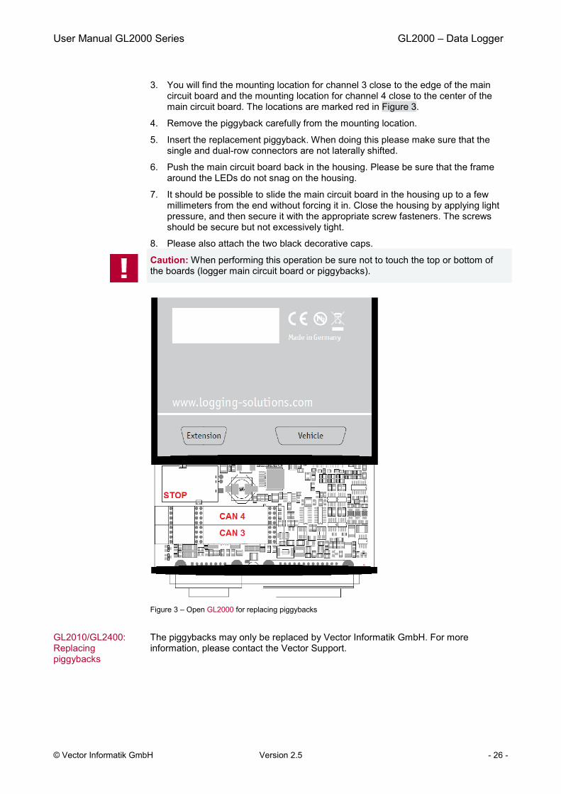
3. You will find the mounting location for channel 3 close to the edge of the main circuit board and the mounting location for channel 4 close to the center of the main circuit board. The locations are marked red in Figure 3.
4. Remove the piggyback carefully from the mounting location.
5. Insert the replacement piggyback. When doing this please make sure that the single and dual-row connectors are not laterally shifted.
6. Push the main circuit board back in the housing. Please be sure that the frame around the LEDs do not snag on the housing.
7. It should be possible to slide the main circuit board in the housing up to a few millimeters from the end without forcing it in. Close the housing by applying light pressure, and then secure it with the appropriate screw fasteners. The screws should be secure but not excessively tight.
8. Please also attach the two black decorative caps.
Caution: When performing this operation be sure not to touch the top or bottom of the boards (logger main circuit board or piggybacks).
Figure 3 – Open GL2000 for replacing piggybacks
GL2010/GL2400: Replacing piggybacks
The piggybacks may only be replaced by Vector Informatik GmbH. For more information, please contact the Vector Support.
User Manual GL2000 Series GL2000 – Data Logger
© Vector Informatik GmbH Version 2.5 - 27 -
2.4.3 LIN
LIN channels LIN frames can be recorded with both internal LIN channels. The sending of LIN frames is not supported on these channels. A LINprobe X or LINprobe G are required for this purpose and is available as a logger accessory.
LIN transceiver The LIN transceivers TJA1021 are already mounted on the main board of the loggers. Therefore LIN piggybacks are not needed.
LIN level The LIN channels are supplied with maximum 12 V from the supply voltage of the data logger. If the reference voltage for a LIN channel is higher than 12 V, this voltage (e.g. 24 V) must be applied to the LIN1_Vbatt or LIN2_Vbatt pins. In all other cases, the LIN1/2_Vbatt pins are not connected.
It is recommended to connect also GND as ground supply beside the LIN pins.
Wake-up capability The logger can be woken up over either LIN channel.
2.5 GPS Mouse
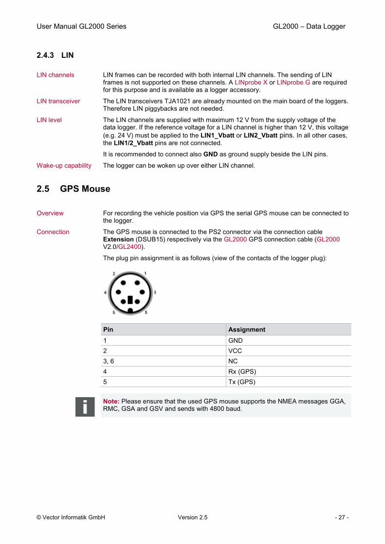
Overview For recording the vehicle position via GPS the serial GPS mouse can be connected to the logger.
Connection The GPS mouse is connected to the PS2 connector via the connection cable Extension (DSUB15) respectively via the GL2000 GPS connection cable (GL2000 V2.0/GL2400).
The plug pin assignment is as follows (view of the contacts of the logger plug):
Pin Assignment 1 GND 2 VCC 3, 6 NC 4 Rx (GPS) 5 Tx (GPS)
Note: Please ensure that the used GPS mouse supports the NMEA messages GGA, RMC, GSA and GSV and sends with 4800 baud.

User Manual GL2000 Series GL2000 – Data Logger
© Vector Informatik GmbH Version 2.5 - 28 -
2.6 Ethernet
Ethernet connector An Ethernet connection with the following function is located on the top cover:
Logger as bus interface
The logger supports a monitoring interface that allows the use of the logger as bus interface for monitoring in CANoe/CANalyzer (since version 8.2).
The logger is connected via Ethernet to the CANoe/CANalyzer PC and sends after measurement start the bus data to CANoe/CANalyzer, where the data can be analyzed in the measurement setup. Sending messages with CANoe/CANalyzer is not possible. The relevant CANoe/CANalyzer licenses must be provided by a connected hardware interface on the PC or by a license dongle.
You can find further information in the Vector Logger Configurator manual, chapter Monitoring Interface. There the configuration of the logger and CANoe/CANalyzer is described in Tutorial: Usage as interface.
Connection of 3G router
The connection of the GL2000 3G router for the GL2000 series enables wireless data transmission via 3G/UMTS. Find more information to 3G/UMTS in chapter 2.7 3G (UMTS).
Connection to a PC via LAN
The logger supports the data transmission to a PC directly via LAN. For data transmission the TransferRequest license must be installed on the logger.
You can set the events that cause a connection and the transfer of logged data from the logger to the destination system in the Vector Logger Configurator.
The data transmission is carried out using the Multi-Logger ML Server software. The basic version is included in the scope of delivery.
2.7 3G (UMTS)
Overview The logger optionally supports wireless data transmission via 3G/UMTS.
The GL2000 3G router for the GL2000 sereis is connected to the Ethernet connection of the logger for this. The router is either permanently supplied externally or via the GLA600 adapter. In the latter case, the router is switched on by the logger only for the duration of the transmission.
The router is certified for the following regions: > EU member states > North America
Please see the technical data in the device manual of the manufacturer.
For data transmission the TransferRequest license must be installed on the logger.
The events that cause a 3G connection and the transfer of logged data from the logger to the destination system can be set in the Vector Logger Configurator.
The data transmission is carried out using the Multi-Logger ML Server software. The basic version is included in the scope of delivery.
A SIM card is not included in the scope of delivery. A contract must be separately entered into with a provider.
User Manual GL2000 Series GL2000 – Data Logger
© Vector Informatik GmbH Version 2.5 - 29 -
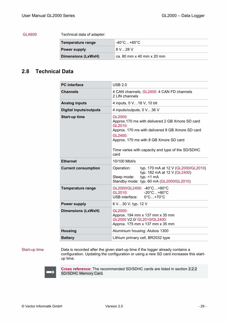
GLA600 Technical data of adapter:
Temperature range -40°C…+85°C
Power supply 8 V…28 V Dimensions (LxWxH) ca. 80 mm x 40 mm x 20 mm
2.8 Technical Data
PC interface USB 2.0 Channels 4 CAN channels, GL2400: 4 CAN FD channels
2 LIN channels Analog inputs 4 inputs, 0 V…18 V, 10 bit Digital inputs/outputs 4 inputs/outputs, 0 V…36 V Start-up time GL2000:
Approx.170 ms with delivered 2 GB Xmore SD card GL2010: Approx. 170 ms with delivered 8 GB Xmore SD card GL2400: Approx. 170 ms with 8 GB Xmore SD card Time varies with capacity and type of the SD/SDHC card
Ethernet 10/100 Mbit/s Current consumption Operation: typ. 170 mA at 12 V (GL2000/GL2010)
typ. 182 mA at 12 V (GL2400) Sleep mode: typ. <1 mA Standby mode: typ. 60 mA (GL2000/GL2010)
Temperature range GL2000/GL2400: -40°C…+80°C GL2010: -20°C…+80°C USB interface: 0°C…+70°C
Power supply 6 V…30 V, typ. 12 V Dimensions (LxWxH) GL2000:
Approx. 194 mm x 137 mm x 35 mm GL2000 V2.0/ GL2010/GL2400: Approx. 175 mm x 137 mm x 35 mm
Housing Aluminium housing: Alubos 1300 Battery Lithium primary cell, BR2032 type
Start-up time Data is recorded after the given start-up time if the logger already contains a configuration. Updating the configuration or using a new SD card increases this start-up time.
Cross reference: The recommended SD/SDHC cards are listed in section 2.2.2 SD/SDHC Memory Card.

User Manual GL2000 Series GL2000 – Data Logger
© Vector Informatik GmbH Version 2.5 - 30 -
2.9 Included with Delivery
Standard scope of delivery
> GL2000 or GL2010 or GL2400 logger > Vector Logger Configurator on CD > Vector Logging Exporter on CD > G.i.N. configuration program on CD > Basic version of Multi-Logger ML Server software > Manuals on CD > 2 GB SD memory card (not for GL2400) > Switch box E2T2L > USB cable > Connection cable Vehicle for DSUB25 > Connection cable Extension DSUB15 with Binder 5-pol (connection for switch
box E2T2L) (not for GL2000 V2.0) > Mounting brackets (GL2000/GL2400 only)
Optional > CCP/XCP license for CAN > TransferRequest license for data transfer to ML Server > GL2010 Ethernet cable IP65/IP20
2.10 Accessories
Optional > 3G modem (incl. antennas) for wireless data transfer > GPS receiver for recording the vehicle position via GPS > LINprobe as extension for the LIN channels > VoCAN for voice recording (1 button, 4 LEDs and signal tone) > CASM2T3L for voice recording (2 buttons, 3 LEDs and signal tone) > CAS1T3L (1 button, 3 LEDs and signal tone) > LOGview for displaying signal and status information
User Manual GL2000 Series Installation Configuration Programs
© Vector Informatik GmbH Version 2.5 - 31 -
3 Installation Configuration Programs
In this chapter you find the following information:
3.1 Overview page 32
3.2 Installation Vector Logger Configurator page 32 Requirements Setup Overview Quick Start
3.3 Installation G.i.N. Configuration Program page 35 Requirements Setup Overview Quick Start

User Manual GL2000 Series Installation Configuration Programs
© Vector Informatik GmbH Version 2.5 - 32 -
3.1 Overview
Overview This instruction describes the installation of the software package for the GL2000 series containing: > Vector Logger Configurator
Graphic user interface for easy configuration > G.i.N configuration program
User interface to create complex configurations with LTL (Log Task Language) The programs are included with delivery.
Vector Logger Configurator
The Vector Logger Configurator offers a wide range of features to easily create configurations for the logger. The Vector Logger Configurator also supports the download of the configuration and the upload of logging data including the export to different file formats. Additionally the configuration can be saved as LTL code to be used in the G.i.N. configuration program.
G.i.N. configuration program
The G.i.N. configuration program can be used as configuration program for high end configurations. It offers full support of all features available with LTL (Log Task Language). This program can be used to import LTL code from the Vector Logger Configurator or from existing configurations written in LTL (e.g. from GL1000) or to write own configurations in LTL.
3.2 Installation Vector Logger Configurator
Overview This instruction describes the installation of the Vector Logger Configurator for the GL2000 series containing: > Vector Logger Configurator > Online help for the Vector Logger Configurator > User manual for the Vector Logger Configurator > This user manual
3.2.1 Requirements
Operating system The following software requirements must be fulfilled to run the Vector Logger Configurator: > Windows 7 / Windows 8.1 (32/64 Bit) > Windows 10 (64 Bit)
Restriction Windows 8.1: AUTOSAR databases are not supported.
User Manual GL2000 Series Installation Configuration Programs
© Vector Informatik GmbH Version 2.5 - 33 -
3.2.2 Setup
Program variants The Vector Logger Configurator can be installed as a 32-bit or 64-bit program. Due to the larger address space, the 64-bit variant can process very extensive databases. 32-bit and 64-bit variants are otherwise functionally identical.
The 64-bit version can only be installed on 64-bit operating systems.
The 32-bit version can be installed on 32-bit and 64-bit operating systems.
The Vector Logger Configurator is installed as follows.
1. Execute the setup, which is found on the installation CD: .\VLConfig\Setup_64Bit.exe or .\VLConfig\Setup_32Bit.exe
2. Please, follow the instructions in the setup program to complete the installation.
3. After successful installation, the Vector Logger Configurator can be found in the start menu (if selected during installation).
4. Also install the basic software e.g. for wireless transmission. The software can be found on the installation CD under .\GLtools\setup.exe
3.2.3 Overview
About Vector Logger Configurator
Vector Logger Configurator enables the configuration of the loggers and offers a wide range of settings. You may set baud rates for CAN and LIN, define triggers and filters, set LEDs and manage logging files on the SD card. Furthermore, for the CAN bus diagnostics and CCP/XCP can be configured. For CCP/XCP the logger needs an installed license. For Seed & Key CANape is required. Vector Logger Configurator also supports trigger and filter access by symbolic names defined in CAN and LIN databases.
Main features are: > Customizable filters for CAN and LIN messages > Customizable triggers > Support of CAN and LIN databases > Support of diagnostics > File management > CCP/XCP (optional)

User Manual GL2000 Series Installation Configuration Programs
© Vector Informatik GmbH Version 2.5 - 34 -
Device Information The Vector Logger Configurator can read out hardware information from the logger. Connect the logger with inserted memory card via USB and select the item File Manager|Logger Device|Device Information in the list view on the left hand side.
Cross reference: The Vector Logger Configurator is described in detail in the user manual of this configuration program. The user manual is available as PDF and can be opened via the program group in the start menu.
3.2.4 Quick Start
Quick start Follow the instructions below to configure the logger, start logging and read out logging data.
1. Start the program.
2. Open a new configuration via the menu File|New Project…. Select in the displayed dialog the logger type GL2000 oder GL2400.
3. Select suitable baud rates for CAN and/or LIN (Hardware|CAN Channels and/or Hardware|LIN Channels), respectively.
4. Select the timeout to sleep mode (Hardware|Settings).
5. Configure the logger for a permanent logging of all data from switching on to switching off of the logger by activating the Use permanent logging option in Logging|Triggers.
6. Insert an empty, FAT32 formatted SD card into the GL2000/GL2400. The SD card is contained in the GL2010.
7. Connect the logger to PC via USB cable. If the logger is not automatically detected, press <F5> to refresh the display of connected logger devices.
8. Download the configuration via menu Configuration|Write to Device….
User Manual GL2000 Series Installation Configuration Programs
© Vector Informatik GmbH Version 2.5 - 35 -
9. Set the real-time clock via menu Device|Set Real-Time Clock… (recommended before first logging).
10. Disconnect the logger from the PC.
11. Connect the logger e.g. to your test system (CAN bus). Switch power on via connecting cable on DSUB25.
12. Start logging. LED1 flashes permanently (standard setting for new configurations, can be configured).
13. Stop logging by switching off CAN. Wait until the logger goes to sleep mode (CAN transceiver with wake-up capability necessary) i.e. LED1 must be off.
14. Connect the logger to PC via USB cable.
15. Open the File Manager node in the tree view.
16. Click on Logger Device|Classic View. Now the logging files are displayed.
17. Select in the General Settings the destination folder and the format for the converted files.
18. Select in the Advanced Settings the options for conversion.
19. Click on the [Convert] button to start the readout and conversion of all data. The files will be located in <Destination folder>/< Destination subdirectory>.
3.3 Installation G.i.N. Configuration Program
Overview This instruction describes the installation of the G.i.N. Configuration Program for the GL2000 series containing: > G.i.N. configuration program > G.i.N. user manuals for the configuration program and the hardware
3.3.1 Requirements
Operating system The following software requirements must be fulfilled to run the G.i.N. configuration program:
Windows 7, Windows 8.1 and Windows 10
3.3.2 Setup
Follow the instructions below to install the G.i.N. configuration program:
1. Execute the setup, which is found on the installation CD: .\GiNconf\setup.exe
2. Please, follow the instructions found there to complete the installation.
3. After successfully installation, the G.i.N. configuration program can be found in the start menu.
4. If you want to use 3G, you also have to install the basic software that can be found on the installation CD under .\GLtools\setup.exe
User Manual GL2000 Series Installation Configuration Programs
© Vector Informatik GmbH Version 2.5 - 36 -
3.3.3 Overview
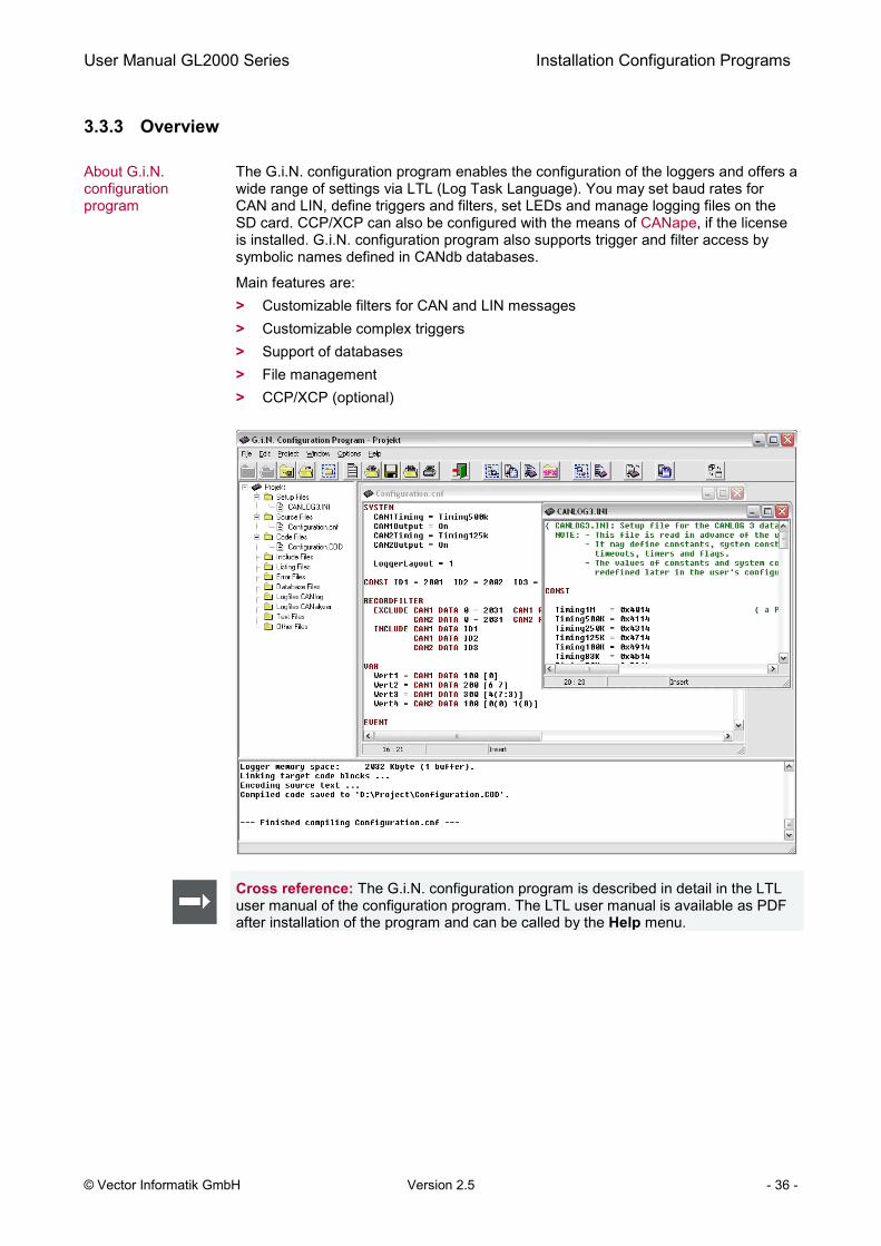
About G.i.N. configuration program
The G.i.N. configuration program enables the configuration of the loggers and offers a wide range of settings via LTL (Log Task Language). You may set baud rates for CAN and LIN, define triggers and filters, set LEDs and manage logging files on the SD card. CCP/XCP can also be configured with the means of CANape, if the license is installed. G.i.N. configuration program also supports trigger and filter access by symbolic names defined in CANdb databases.
Main features are: > Customizable filters for CAN and LIN messages > Customizable complex triggers > Support of databases > File management > CCP/XCP (optional)
Cross reference: The G.i.N. configuration program is described in detail in the LTL user manual of the configuration program. The LTL user manual is available as PDF after installation of the program and can be called by the Help menu.

User Manual GL2000 Series Installation Configuration Programs
© Vector Informatik GmbH Version 2.5 - 37 -
3.3.4 Quick Start
Quick start Follow the instructions below to configure the logger, start logging and readout logging data.
1. Start the program.
2. Create a new project (File|New Project). Select the project path and the device GL2000.
3. Create a new source file (File|New File) and set the baud rate for CAN and the timeout for sleep mode, e.g. SYSTEM Can1Timing = Timing500K Can2Timing = Timing500K SleepSeconds = 5 END
4. Save the file (File|Save File as) as LTL file in your project directory.
5. Compile this file via Project|Compile or press [F9]. A COD file is created.
6. Insert an empty, FAT32 formatted SD card in the logger. The SD card is contained in the GL2010.
7. Connect the logger to PC via USB cable.
8. Download the COD file with [F10] or via Project|Compile and Download.
9. Disconnect the logger from PC.
10. Connect the logger e.g. to your test system (CAN bus). Switch power on via connecting cable on DSUB25.
11. Start logging.
12. Stop logging by switching off CAN. Wait until the logger goes to sleep mode (CAN transceiver with wake-up capability necessary).
13. Connect logger to PC via USB cable.
14. Start the control program with [F11] or via Project|Run Control Program. Select Read out and Export after readout for the CAN logfile and click on [OK].
15. Select the destination directory for the logging files. The upload is started afterwards.
16. The log files are uploaded in a raw format and displayed in the tree view under Logfiles GiN Logger.
17. After readout the Export dialog is automatically displayed. Select the file format and export parameters and click on [OK]. The raw log file is now converted to the selected file format.

User Manual GL2000 Series Index
© Vector Informatik GmbH Version 2.5 - 39 -
4 Index
3
3G (UMTS) ......................................................... 28
A
Analog inputs ...................................................... 19
B
Battery................................................................. 19
Beep.................................................................... 21
C
CAN .............................................................. 24, 25
CCP/XCP ............................................................ 22
Configuration mode ............................................ 23
Connection cable ................................................ 12
Connectors ......................................................... 11
D
Delivery ............................................................... 30
Device information .............................................. 34
Diagnostics ......................................................... 23
Digital input/output .............................................. 18
DSUB15 .............................................................. 12
DSUB25 .............................................................. 11
E
Ethernet .............................................................. 28
F
FAT32 ................................................................. 14
Features .............................................................. 11
G
G.i.N configuration program................................ 35
GPS mouse ........................................................ 27
L
Layout GL2000 ............................................. 21, 26
LED .................................................................... 17
LIN...................................................................... 27
Logging mode .................................................... 23
M
Memory cards .................................................... 14
O
Operating modes ............................................... 23
P
Piggybacks ......................................................... 24
Pin assignment ............................................ 11, 12
Q
Quick start .................................................... 34, 37
R
Real-time clock .................................................. 19
Requirements ............................................... 32, 35
S
Safety instruction ................................................. 7
SD/SDHC ........................................................... 14
Serial interface ................................................... 19
Serial number ..................................................... 16
Sleep .................................................................. 21
Start-up time ...................................................... 29
Support ................................................................ 5
T
Technical data .................................................... 29
Transceiver .................................................. 24, 25
U
UMTS ................................................................. 28
V
Vector Logger Configurator ............................... 32

User Manual GL2000 Series Index
© Vector Informatik GmbH Version 2.5 - 40 -
W Wake-up ............................................................. 21


More Information
> News > Products > Demo Software > Support > Training Classes > Addresses
www.vector.com