user manual - spectrafy.com · user information spectrafy inc. strongly recommends reading this...
TRANSCRIPT
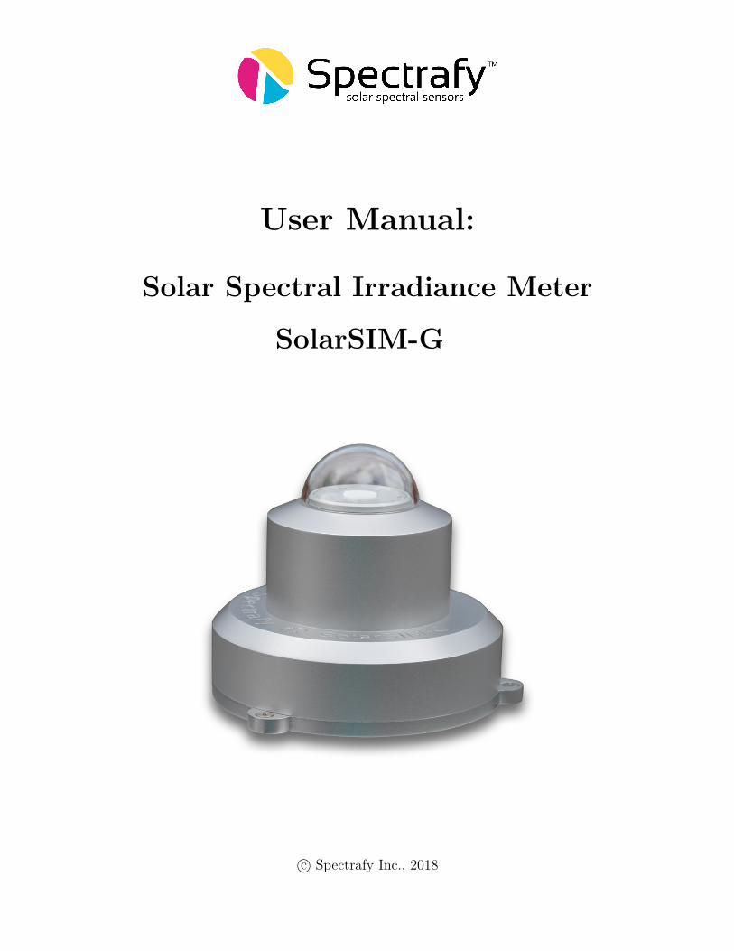
User Manual:
Solar Spectral Irradiance Meter
SolarSIM-G
c© Spectrafy Inc., 2018

User informationSpectrafy Inc. strongly recommends reading this instruction manual prior to installation andoperation of your global Solar Spectral Irradiance Meter (SolarSIM-G).
If you have any comments about this manual or our products, please send them to:
Spectrafy Inc. Inc.4 Florence St, Suite 204Ottawa, Ontario, CanadaK2P 0W7Tel: [email protected]
www.spectrafy.com
Spectrafy Inc. reserves the right to make modifications to the user manual without priornotice.
Warranty and liabilitySpectrafy Inc. guarantees that the Solar Spectral Irradiance Meter (SolarSIM-G) has beenthoroughly tested to ensure that it meets all of the stated specifications. A two year warrantyis provided from date of invoice, subject to correct installation and operation. Spectrafy Inc.accepts no liability for any loss or damages arising from improper usage of this product.
i
ContentsIntroduction 1
1 Main components 21.1 Glass dome . . . . . . . . . . . . . . . . . . . . . . . . . . . . . . . . . . . . 31.2 Enclosure . . . . . . . . . . . . . . . . . . . . . . . . . . . . . . . . . . . . . 31.3 Bandpass filters . . . . . . . . . . . . . . . . . . . . . . . . . . . . . . . . . . 31.4 Bubble level . . . . . . . . . . . . . . . . . . . . . . . . . . . . . . . . . . . . 31.5 Connector . . . . . . . . . . . . . . . . . . . . . . . . . . . . . . . . . . . . . 31.6 Backplate . . . . . . . . . . . . . . . . . . . . . . . . . . . . . . . . . . . . . 3
2 Installation 42.1 Contents of delivery . . . . . . . . . . . . . . . . . . . . . . . . . . . . . . . . 42.2 Mechanical installation . . . . . . . . . . . . . . . . . . . . . . . . . . . . . . 4
3 Maintenance 63.1 Cleaning . . . . . . . . . . . . . . . . . . . . . . . . . . . . . . . . . . . . . . 63.2 Alignment . . . . . . . . . . . . . . . . . . . . . . . . . . . . . . . . . . . . . 63.3 Desiccant . . . . . . . . . . . . . . . . . . . . . . . . . . . . . . . . . . . . . 63.4 Recalibration . . . . . . . . . . . . . . . . . . . . . . . . . . . . . . . . . . . 6
4 Connectivity 74.1 SolarSIM-G Communication Box . . . . . . . . . . . . . . . . . . . . . . . . 84.2 Serial-over-Ethernet converter . . . . . . . . . . . . . . . . . . . . . . . . . . 84.3 Datalogger . . . . . . . . . . . . . . . . . . . . . . . . . . . . . . . . . . . . . 10
5 SolarSIM-G DAQ Application 105.1 Software installation . . . . . . . . . . . . . . . . . . . . . . . . . . . . . . . 105.2 Software settings . . . . . . . . . . . . . . . . . . . . . . . . . . . . . . . . . 105.3 Using the software . . . . . . . . . . . . . . . . . . . . . . . . . . . . . . . . 115.4 Data type and storage . . . . . . . . . . . . . . . . . . . . . . . . . . . . . . 145.5 Data collection size . . . . . . . . . . . . . . . . . . . . . . . . . . . . . . . . 155.6 Changing default language for non-Unicode characters . . . . . . . . . . . . 16
6 Datalogger setup 186.1 Serial port configuration . . . . . . . . . . . . . . . . . . . . . . . . . . . . . 186.2 Serial commands . . . . . . . . . . . . . . . . . . . . . . . . . . . . . . . . . 186.3 Raw data file format . . . . . . . . . . . . . . . . . . . . . . . . . . . . . . . 206.4 SolarSG application . . . . . . . . . . . . . . . . . . . . . . . . . . . . . . . . 21
ii
List of Figures1 SolarSIM-G components and main dimensions. . . . . . . . . . . . . . . . . . 22 Assembled SolarSIM-G on a mounting plate. . . . . . . . . . . . . . . . . . . 53 Dimensional drawing of a mounting plate. . . . . . . . . . . . . . . . . . . . 54 The SolarSIM-G ComBox. . . . . . . . . . . . . . . . . . . . . . . . . . . . . 75 Server configuration for VxComm software. . . . . . . . . . . . . . . . . . . . 96 Port configuration for VxComm software. . . . . . . . . . . . . . . . . . . . . 97 Installation of the SolarSIM-G software. . . . . . . . . . . . . . . . . . . . . 108 Adjustment of the SolarSIM-G user settings. . . . . . . . . . . . . . . . . . . 119 Browsing to the calibration file. . . . . . . . . . . . . . . . . . . . . . . . . . 1310 Selecting multiple calibration files. . . . . . . . . . . . . . . . . . . . . . . . . 1311 Failing to detect the SolarSIM-G. . . . . . . . . . . . . . . . . . . . . . . . . 1312 Changing and verifying geographic settings. . . . . . . . . . . . . . . . . . . 1313 SolarSIM-G DAQ application . . . . . . . . . . . . . . . . . . . . . . . . . . 1414 SolarSIM-G spectrum data file snippet. . . . . . . . . . . . . . . . . . . . . . 1515 SolarSIM-G daily summary file snippet. . . . . . . . . . . . . . . . . . . . . . 1516 Clock, Language, and Region settings in the Control Panel. . . . . . . . . . 1617 Changing the system locale. . . . . . . . . . . . . . . . . . . . . . . . . . . . 1618 Changing the default language for non-Unicode characters. . . . . . . . . . . 1719 SolarSG input file snippet. . . . . . . . . . . . . . . . . . . . . . . . . . . . . 2020 Modifying geographic settings for the SolarSG application. . . . . . . . . . . 21
List of Tables1 Wiring guide for the SolarSIM-G. . . . . . . . . . . . . . . . . . . . . . . . . 82 SolarSIM-G DAQ program settings. . . . . . . . . . . . . . . . . . . . . . . . 123 SolarSIM-G serial port configuration. . . . . . . . . . . . . . . . . . . . . . . 184 Processed output example for Nxxxx E command. . . . . . . . . . . . . . . . 19
iii

IntroductionDear customer, thank you for purchasing the Solar Spectral Irradiance Meter (SolarSIM-G)from Spectrafy Inc. Please become familiar with this instruction manual for a full under-standing of the use of your SolarSIM-G.
The SolarSIM-G is designed to be a cost-effective tool for accurately determining the solarspectrum and global horizontal/tilted irradiance (GHI/GTI) as part of on-site solar resourceassessments and module performance characterization studies. The instrument uses siliconphotodiodes, integrated with hard-coated bandpass filters to measure the solar spectral irra-diance in nine narrow wavelength bands. The SolarSIM-G’s proprietary software uses thesemeasurements to resolve the global solar spectrum and the global irradiance.
If you have any questions, please feel free to contact a Spectrafy representative or [email protected]
1

1 Main componentsThe side view of SolarSIM-G components is shown in Figure 1, which includes
• a glass dome,• an enclosure,• bandpass filters,• bubble level,• a connector, and• a backplate.
Figure 1: SolarSIM-G components and main dimensions.
2
1.1 Glass domeThe glass dome prevents the ingress of moisture and debris.
1.2 EnclosureThe anodized aluminum enclosure secures SolarSIM-G components in place, while providingrobust protection from the environment.
1.3 Bandpass filtersNine bandpass filters transmit a narrow band of spectral irradiance to the detectors.
1.4 Bubble levelThe bubble level ensures the SolarSIM-G is leveled when measuring the irradiance in globalhorizontal orientation.
1.5 ConnectorThe connector provides the power and communication to the SolarSIM-G electronics.
1.6 BackplateThe anodized aluminum backplate seals the back of the enclosure with four screws.
3

2 Installation
2.1 Contents of deliveryPer each ordered SolarSIM-G the received package should contain:
• a SolarSIM-G ×1,• a communication cable ×1,• a SolarSIM-G Communication Box ×1 (optional),• a mounting plate ×1 (optional),• mounting screws ×3,• mounting springs ×3, and• a USB key loaded with the SolarSIM-G software.
Please check the contents of the package and note if any damages have occurred duringshipment. A claim should be filed with the shipment carrier should this be the case. Addi-tionally, please contact a Spectrafy representative to facilitate the repair or replacement ofthe instrument and/or its accessories.
2.2 Mechanical installationThe SolarSIM-G installation requires fastening it to the mounting plate via three M4 screwsand springs, as demonstrated in Figure 2. The mounting plate is 7.3 mm thick and hasthree slots with a 132 mm diameter that are 4.5 mm wide for external fastening, as shown inFigure 3. The screws for external mounting are not provided. The procedure for mechanicalinstallation is described as follows:
1. Place the SolarSIM-G on the mounting plate as per Figure 3.2. Place the spring under the SolarSIM-G so that it roughly aligns with one of the
mounting holes on the SolarSIM-G.3. Insert the mounting screw through the SolarSIM-G’s mounting hole and the
spring. Then thread the screw into the mounting plate for a few revolutions, only.4. Repeat steps 2 and 3 for the remaining two screws and springs.5. Tighten all screws to compress the springs by about 10 mm.6. Adjust the mounting screws until the bubble level is centered with the bulls eye.
4

Figure 2: Assembled SolarSIM-G on a mounting plate.
Figure 3: Dimensional drawing of a mounting plate.
5
3 MaintenanceThe SolarSIM-G requires very little maintenance. The most important task is to make surethat the glass dome of the SolarSIM-G is clean at all times, as the accumulation of dirtcan lead to misrepresented data. Furthermore, the horizontal alignment of the SolarSIM-Gshould be checked periodically.
3.1 CleaningAs a general rule, we recommend cleaning the SolarSIM-G’s front glass with a dry, non-abrasive cloth, or paper towel, once per week, in order to maintain optimum performance.This frequency can be altered depending on your local climatic conditions.
3.2 AlignmentWith each cleaning, it is also advised to check the leveling of the instrument using the bubblelevel. If the bubble is not centered within the circle, adjust the appropriate mounting screwsto re-level the SolarSIM-G.
3.3 DesiccantThe desiccant is used to maintain an appropriate humidity level within the SolarSIM-G.The internal humidity of the device is reported within the daily summary data files and cantherefore be monitored over time. The lifetime of the desiccant is expected to exceed twoyears, although it may vary based on local climatic conditions. The desiccant can be replacedas part of the SolarSIM-G’s re-calibration procedure.
3.4 RecalibrationWe recommend that the SolarSIM-G is returned to Spectrafy for recalibration every 1-2 yearsin order to maintain the SolarSIM’s specified measurement accuracy.
6

4 ConnectivityThe SolarSIM-G offers various connectivity options suitable for most use case scenarios. Theconnectivity solutions include:
1. A SolarSIM ComBox2. A serial-over-Ethernet converter, or3. A datalogger.
Option 1 uses the SolarSIM Communication Box (ComBox) - a seamless link between aPC and the SolarSIM-G, as shown in Figure 4. A standard 6 ft USB cable is connected fromthe ComBox to a PC. On the other side, a 10 m RS-485 communication cable is connectedfrom the ComBox to the SolarSIM-G. This option is ideal for test sites and locations whereone has the access to a personal computer (PC) or when quick, in-field spectral measurementsare necessary with a laptop.
Option 2 allows the user to interface with the SolarSIM-G via a serial-over-Ethernetconverter, provided there is Internet access. For this option the user must manually connectthe power and communication wires to the SolarSIM-G by following the wiring guide inSection 4.2. This option is ideal for test sites and locations which have Internet access, but noPC nearby. Both options 1 and 2 make use of the SolarSIM-G DAQ graphical user interface,which must be installed on a Windows-based PC or a server, as explained in Section 5.
Option 3 uses a datalogger to acquire raw data from the SolarSIM-G. This raw datamust be specifically formatted by the user into a .csv file, which is then fed into the SolarSGsoftware to generate the complete SolarSIM-G data set, as further detailed to in Section 6.3.This option is ideal for remote test sites and locations with existing datalogger systems.
Figure 4: The ComBox is necessary to interface the SolarSIM-G wih a PC.
7

4.1 SolarSIM-G Communication BoxThe ComBox is the best option for stable communication between a PC and the SolarSIM-G.Please follow these steps to install the ComBox:
1. Connect one end of the communication cable to the SolarSIM-G.2. Connect the other end to the ComBox.3. Connect one end of a male-to-male USB cable to the ComBox.4. Connect the other end of a male-to-male USB cable to a PC. A blue LED on the
top of the ComBox indicates power to the SolarSIM-G.5. Wait for the PC to install the FTDI drivers, which may take a few minutes.6. Once the FTDI drivers are installed, restart the PC.
4.2 Serial-over-Ethernet converterFor remote test site applications the SolarSIM-G can be connected to anetworked PC via a suitable serial-over-Ethernet (SOE) converter - suchas the ICP DAS I-7188-E21. The user must connect the SolarSIM-G com-munication cable wires as per Table 1. More specifically, the D+ and D−lines, brown and black wires, respectively, must be connected to the cor-responding terminal block inputs on the SOE device, while the blue andwhite wires - to the positive and common ground sides of the 12 VDC po-wer supply, respectively. The SOE converter and the power supply musthave a common ground. Note, supplying the SolarSIM-G with the voltagehigher than 12 VDC will damage the SolarSIM-G electronics.
The network must assign a static IP address to the SOE converter. Afterwards, avirtual communication link can be established via the VxComm software2. The latter mustbe configured as per Figures 5 and 6. Once properly configured, the VxComm software
1https://www.icpdas-usa.com/i_7188e2.html2http://ftp.icpdas.com/pub/cd/8000cd/napdos/driver/vxcomm_driver/windows/
Table 1: Wiring guide for the SolarSIM-G.
Colour Label FunctionBlue Vin Input voltage (+12 VDC)
White GND Common groundBlack D− Negative RS-485 inputBrown D+ Positive RS-485 input
∗12 VDC only
8

creates a virtual serial port on the networked PC, which the SolarSIM-G DAQ applicationuses to communicate to the SolarSIM-G.
Figure 5: Server configuration for VxComm software. Note, the SolarSIM-G supports onlythe ASCII RS-485 communication mode.
Figure 6: Port configuration for VxComm software. Note, the SolarSIM-G supports onlythe ASCII RS-485 communication mode.
9

4.3 DataloggerThe connectivity with a datalogger is similar to the SolarSIM-G’s integration with the SOEconverter. The SolarSIM-G communication cable is connected to the corresponding datalog-ger inputs as per Section 4.2. The datalogger must have a spare RS-485 port.
5 SolarSIM-G DAQ ApplicationThe SolarSIM-G DAQ application provides the user with the real-time status of the instru-ment, data acquisition and storage, and daily data plots. The SolarSIM-G DAQ softwarecommunicates via a serial port and thus can be used with either a ComBox or a SOE conver-ter. This section will go over the software installation, the program settings, and the generalknow-how for using the SolarSIM-G DAQ.
5.1 Software installationThe software installation is performed by executing the setup.exe inside the SolarSIM setupfolder located on the provided USB key, as shown in Figure 7. The user should follow theinstallation instructions as prompted by the software.
5.2 Software settingsOnce the SolarSIM-G software is installed, the user must define the location-specific geo-graphic settings for the SolarSIM-G to work properly. This process can be accomplished
Figure 7: Installation of the SolarSIM-G software
10
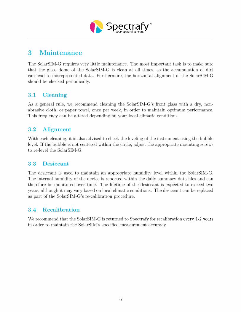
Figure 8: Adjustment of the SolarSIM-G user settings.
in two ways. The first option is for the user to change the values for altitude, longitude,and latitude in the user settings.conf file, located in the Settings folder of the installationdirectory, as shown in Figure 8. The second option is to modify these parameters when auto-matically prompted by the software, as will be explained in Section 5.3. The modifications ofthe remaining parameters is optional. If Auto mode is ON, upon launching, the applicationdoes not interact with the user and begins the data collection automatically. The DAQ timersets the data acquisition rate for the entire SolarSIM-G data set. If it is desired to have aseparate data rate for the spectral data, the user can turn ON the Custom spectrum timerand change the spectral data acquisition to a desired rate via the Spectrum timer. Pleaserefer to Table 2 for the summary of the user settings.
5.3 Using the softwareThe SolarSIM-G software is launched by double-clicking the SolarSIM-G DAQ.exe in theinstallation directory. The application runs automatically in the administrator mode, as it
11
Table 2: SolarSIM-G DAQ program settings.
Setting Value range UnitsAltitude 0.0 to 9000.0 metres
Longitude 0.00 to 180.00∗ degreesLatitude 0.00 to 90.00∗∗ degrees
Auto mode 0 or 1 OFF or ONDAQ timer 1.0 to 3600.0 seconds
Custom spectrum timer 0 or 1 OFF or ONSpectrum timer 0 or 1 OFF or ON
∗longitude is negative for western hemisphere∗∗latitude is negative for southern hemisphere
is a prerequisite to save data in the Program �les directory. Once launched, the programautomatically searches for the SolarSIM-G calibration file. If none is found, the SolarSIM-GDAQ will prompt the user to browse to the calibration file’s directory, as shown in Figure 9.Browse to the provided USB key and select the appropriate calibration file. The applicationthen copies this file to the Settings folder and will not ask for it again. If the SolarSIM-GDAQ detects multiple calibration files, the application will prompt the user to select thedesired SolarSIM-G, as shown in Figure 10.
Once the calibration file is loaded, the SolarSIM-G DAQ software searches for the serialport to which the SolarSIM-G is connected. If the SolarSIM-G is not detected, the programdisplays the message as shown in Figure 11 and exits. In this case, please ensure that your PCdetects the serial port by viewing the available serial or COM ports in the Device manager.If similar problem arises with the SOE converter, please double-check the setup procedureas explained in Section 4.2.
Once the SolarSIM-G is found, the SolarSIM-G DAQ prompts the user to verify and/orchange the geographic settings, which include altitude, longitude and latitude, as shown inFigure 12. If these parameters are incorrect, the user can change them by modifying theappropriate values in the pop-up window. When ready, press Apply, and the program willsave these settings permanently by writing them to the user settings.conf file. Please notethat the latitude and longitude must be negative for southern and western hemispheres,respectively.
The SolarSIM-G DAQ is depicted in Figure 13. The software displays the daily plots ofthe photodiode currents, the ambient temperature and pressure, the GHI in the 350–1830 nmand the 280–4000 nm ranges, the aerosol optical depth, the ozone content, the water vapouramount, and, elevation and azimuth angles. Data for all plots, other than the ambienttemperature and pressure, is recorded between the sunrise and the sunset. Furthermore, thereal-time plot of the solar spectrum is provided.
The desired DAQ timer rate (left of the Start DAQ button) should be set before begin-
12
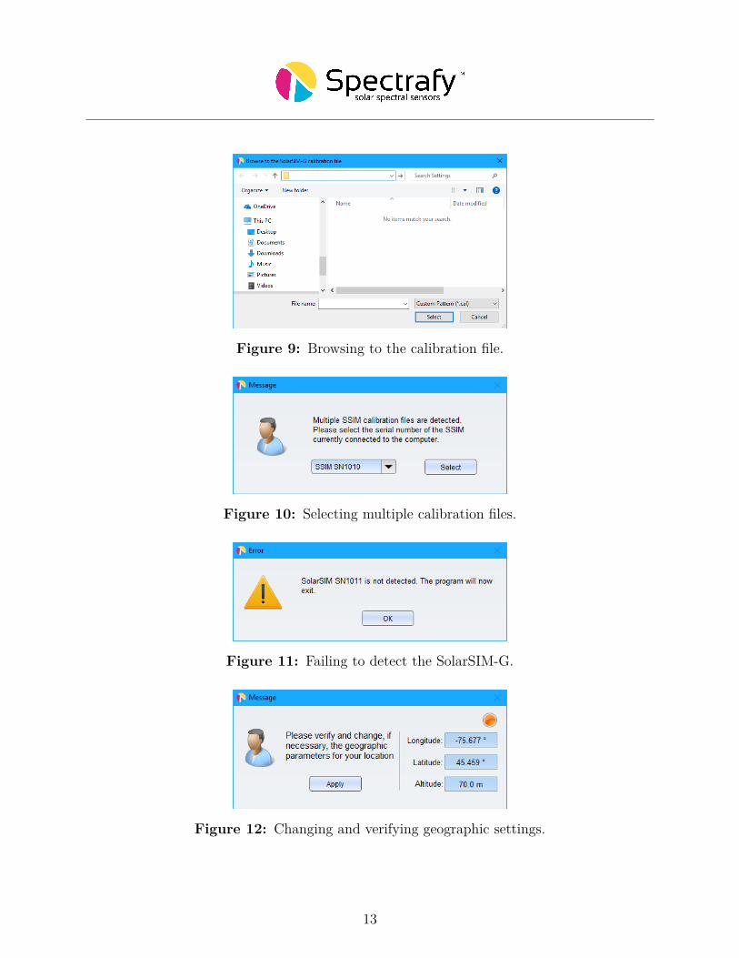
Figure 9: Browsing to the calibration file.
Figure 10: Selecting multiple calibration files.
Figure 11: Failing to detect the SolarSIM-G.
Figure 12: Changing and verifying geographic settings.
13
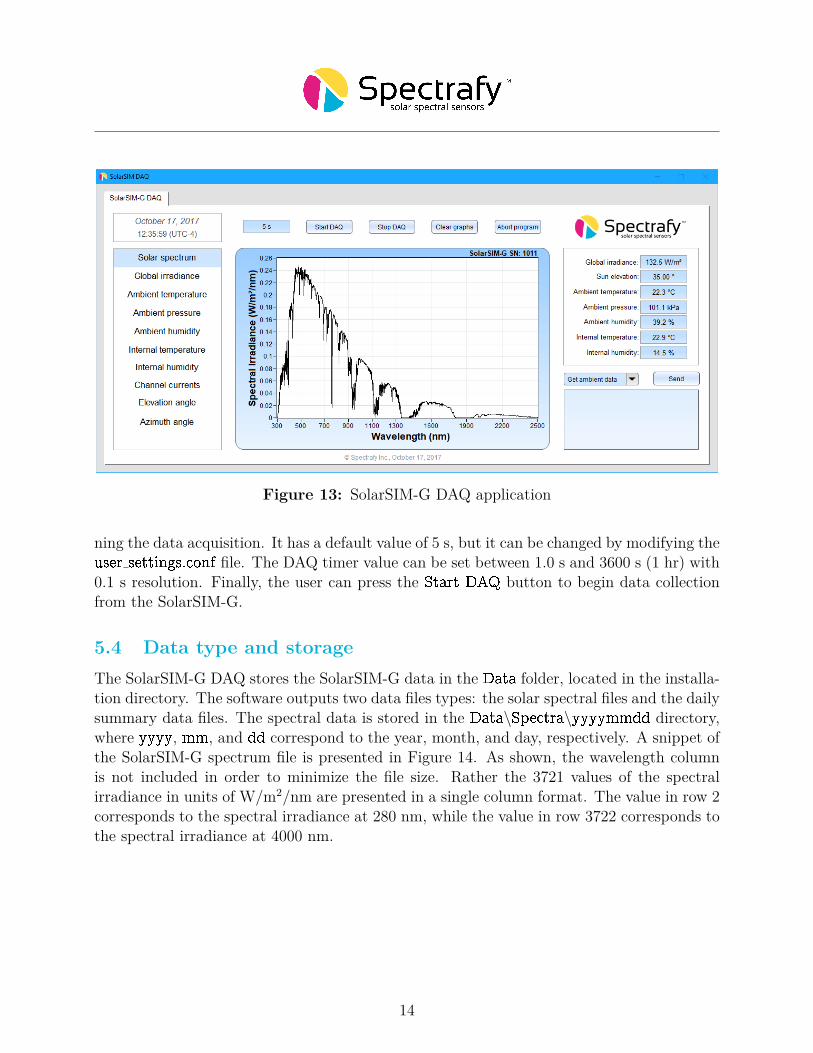
Figure 13: SolarSIM-G DAQ application
ning the data acquisition. It has a default value of 5 s, but it can be changed by modifying theuser settings.conf file. The DAQ timer value can be set between 1.0 s and 3600 s (1 hr) with0.1 s resolution. Finally, the user can press the Start DAQ button to begin data collectionfrom the SolarSIM-G.
5.4 Data type and storageThe SolarSIM-G DAQ stores the SolarSIM-G data in the Data folder, located in the installa-tion directory. The software outputs two data files types: the solar spectral files and the dailysummary data files. The spectral data is stored in the Data\Spectra\yyyymmdd directory,where yyyy, mm, and dd correspond to the year, month, and day, respectively. A snippet ofthe SolarSIM-G spectrum file is presented in Figure 14. As shown, the wavelength columnis not included in order to minimize the file size. Rather the 3721 values of the spectralirradiance in units of W/m2/nm are presented in a single column format. The value in row 2corresponds to the spectral irradiance at 280 nm, while the value in row 3722 corresponds tothe spectral irradiance at 4000 nm.
14
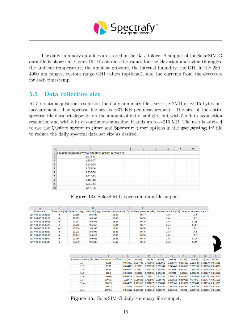
The daily summary data files are stored in the Data folder. A snippet of the SolarSIM-Gdata file is shown in Figure 15. It contains the values for the elevation and azimuth angles,the ambient temperature, the ambient pressure, the internal humidity, the GHI in the 280–4000 nm ranges, custom range GHI values (optional), and the currents from the detectorsfor each timestamp.
5.5 Data collection sizeAt 5 s data acquisition resolution the daily summary file’s size is ∼2MB or ∼115 bytes permeasurement. The spectral file size is ∼37 KB per measurement. The size of the entirespectral file data set depends on the amount of daily sunlight, but with 5 s data acquisitionresolution and with 8 hr of continuous sunshine, it adds up to ∼210 MB. The user is advisedto use the Custom spectrum timer and Spectrum timer options in the user settings.ini fileto reduce the daily spectral data set size as desired.
Figure 14: SolarSIM-G spectrum data file snippet.
Figure 15: SolarSIM-G daily summary file snippet.
15

5.6 Changing default language for non-Unicode charactersFor users of computers with non-Latin based languages, such as Chinese, the SolarSIM-GDAQ may improperly display non-Unicode characters. To solve this problem, the user mustchange the default language for non-Unicode programs to English. To do so, first locate theClock, Language, and Region settings in the Control Panel, then click on Region settings,as show in Figure 16. Then navigate to the Administrative tab and select Change systemlocale..., as demonstrated in Figure 17. Lastly, change the language to English from the dropdown menu, as shown in Figure 18, and press OK.
Figure 16: Clock, Language, and Region settings in the Control Panel.
Figure 17: Changing the system locale in the Administrative tab of the Region settings.
16
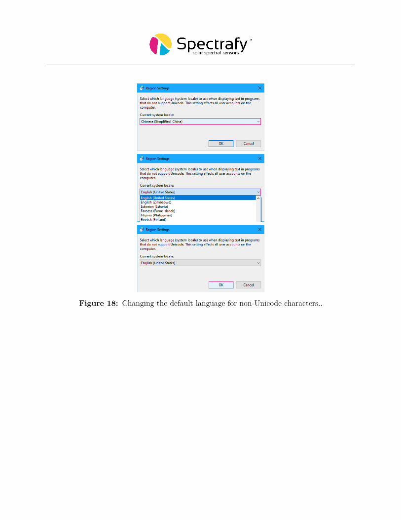
Figure 18: Changing the default language for non-Unicode characters..

6 Datalogger setupThe SolarSIM-G can be interfaced with any datalogger, provided the latter has the RS-485functionality. However, compared to other SolarSIM-G connectivity options, this approachis slightly more involved. In a nutshell, the user must execute the following steps to processthe data from the SolarSIM-G:
1. Setup the serial communication between the datalogger and the SolarSIM-G.2. Send the serial command from the datalogger to the SolarSIM-G.3. Retrieve the raw data from the datalogger.4. Format the raw data into a specific format.5. Place the formatted raw data files into the SolarSG software’s directory and run
the application.
This section discusses in detail how to proceed with each step, including the serial portconfiguration, sending and parsing the serial command, formatting the SolarSIM-G raw datainto a required format, and how to use the SolarSG software.
6.1 Serial port configurationPrior to configuring the serial port on a datalogger, the user must wire the SolarSIM-G byfollowing instructions from Section 4.2. The serial port is then configured with standardserial parameters as per Table 3.
6.2 Serial commandsThere is only one serial command that one needs to use to acquire the SolarSIM-G data:
Nxxxx Ewhere xxxx corresponds to the 4-digit serial number of your SolarSIM-G. In return, theSolarSIM-G sends an ASCII string with the ambient pressure, external temperature, internaltemperature, relative humidity, and seven voltages from the detectors. The following ASCIIstring is a sample output:
Table 3: SolarSIM-G serial port configuration.
Parameter ValueBaud rate 9600
Parity NoneData bits 8Stop bits 1
18
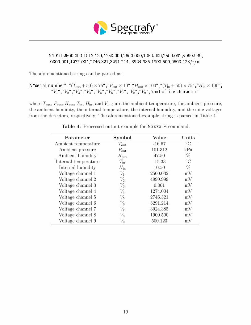
N1010 2500.000,1013.120,4750.000,2600.000,1050.000,2500.032,4999.999,0000.001,1274.004,2746.321,3291.214, 3924.385,1900.500,0500.123/r/n
The aforementioned string can be parsed as:
N\serial number" \(Tout+50)× 75",\Pout× 10",\Hout× 100",\(Tin+50)× 75",\Hin× 100",\V1",\V2",\V3",\V4",\V5",\V6",\V7",\V8",\V9",\end of line character"
where Tout, Pout, Hout, Tin, Hin, and V1−9 are the ambient temperature, the ambient pressure,the ambient humidity, the internal temperature, the internal humidity, and the nine voltagesfrom the detectors, respectively. The aforementioned example string is parsed in Table 4.
Table 4: Processed output example for Nxxxx E command.
Parameter Symbol Value UnitsAmbient temperature Tout -16.67 ◦C
Ambient pressure Pout 101.312 kPaAmbient humidity Hout 47.50 %
Internal temperature Tin -15.33 ◦CInternal humidity Hin 10.50 %Voltage channel 1 V1 2500.032 mVVoltage channel 2 V2 4999.999 mVVoltage channel 3 V3 0.001 mVVoltage channel 4 V4 1274.004 mVVoltage channel 5 V5 2746.321 mVVoltage channel 6 V6 3291.214 mVVoltage channel 7 V7 3924.385 mVVoltage channel 8 V8 1900.500 mVVoltage channel 9 V9 500.123 mV
19

6.3 Raw data file formatThe SolarSG software requires a .csv file in a specific format based on the SolarSIM-Graw data output. The file must have the following headings with the corresponding data:Timestamp, Time zone (hr), Ambient pressure (kPa), Ambient temperature (C), Ambienthumidity (%),Internal temperature (C), Internal humidity (%), V1 (mV), V2 (mV), V3(mV), V4 (mV), V5 (mV), V6 (mV), V7 (mV),V8 (mV), and V9 (mV). Each data row mustconsists of comma separated values only, with no spaces in between. The timestamp must bestrictly in the yyyy-mm-dd HH:MM:SS format, where yyyy, mm, dd, HH, MM, and SS is theyear, month, day, hour, minute, and second, respectively. The SolarSG software uses the timestamp and the timezone from the raw data file to determine the UTC time, which is necessaryfor the solar position algorithm. Therefore, the user must ensure that each time stamp plusthe timezone corresponds to the UTC time. The snippet of the raw data file is presented inFigure 19. The raw data file must be named as yyyy-mm-dd SSIM Raw Data SNxxxx.csv,where yyyy, mm, dd correspond to the year, month, and day when the raw SolarSIM-G datawas generated, while xxxx is a 4-digit serial number of your SolarSIM-G.
Figure 19: SolarSG input file snippet.
20

6.4 SolarSG applicationThe SolarSG application is an executable that the user must run to process the raw datafrom the SolarSIM-G into the spectral data. This software is located on the provided USBkey inside a folder with contents as per Figure 20, which initially include:
1. atmParam.data
2. SolarSG.exe
3. SSIM Calibration SNxxxx.json
4. user settings.conf
Pleas note, the calibration file for the SolarSG application is in a .json format, in contrast tothe .cal file format used by the SolarSIM-G DAQ. Prior to running the SolarSG applicationthe user must configure the local geographic settings in the user settings.ini file, by modifyingthe altitude, longitude, and latitude, corresponding to the location of your SolarSIM-G, asshown in Figure 20. Please refer to Table 2 for the allowed ranges and the positive/negativeconvention of these parameters. Finally, place the raw data .csv file(s) formatted as perSection 6.3 in the SolarSG directory and launch the application.
Once launched, the SolarSG application scans the directory for new raw data files. Ifraw data files are found, the software processes each file line-by-line. The SolarSG applicationcreates three folders in the data folder - Processed Data\\Global. The daily summary �lesand spectrum folders contain identical data to that which SolarSIM-G DAQ generates asexplained in Section 5.4. The archive folder contains all processed raw data files.
Figure 20: Modifying geographic settings for the SolarSG application.
21