user manual - intepro · intepro systems provides a full range of technical support for our...
TRANSCRIPT

Variable Frequency Power Supply
USER MANUAL
©2015 All rights reserved by Intepro Systems
Version 1
Intepro Systems
AFV Series

Version History
Version No.
Release date
Writer Description Hardware version applied
V1.0 3-2015 Rev 1

Intepro Systems provides a full range of technical support for our customers. Customers can contact our offices or customer service centers nearby, or our headquarters. All rights reserved. This manual is subject to change without notice.
Safety Precautions
Danger
Beware of the high temperature of this equipment. DO NOT open the chassis without technician present or authorization from Intepro Systems.
• When the AFV needs to be moved or rewired, please shut down the instrument completelyby disconnecting the input power lines and wait at least 20 minutes for the capacitors in the instrument to discharge to prevent electric shock.
• In order to ensure the personal safety of users, this series of power products must be grounded before use.
• In case of fire, please use dry powder fire extinguishers instead of liquid fire extinguishersto avoid the risk of electric shock.
• Liquid or other foreign objects must not be allowed to enter the cabinet of the grid simulator.
Attention
The application environment and storage methods affect the service life and reliability of the product. Extended use in the following conditions should be avoided:
• Ambient high or low temperatures or humidity beyond technical specifications (temperature:-20℃to 40℃; relative humidity: 5% to 95%);
• In direct sunlight or exposed to heat sources;
• Places susceptible to vibration or collision;
• Environments with dust, corrosive substances, salt and combustible gases;
Keep the air inlets and outlets unblocked to promote ventilation to avoid a rise in the internal temperature, which
may shorten the service life of components, and affect the service life of the product;
Grid simulators not in service for a long time should be stored in a dry environment. The temperature range for storage is -40℃to 70℃.
To properly protect the equipment, only the personnel of Intepro Systems are allowed to open the front door or side cover. If the quality assurance seal is broken, required services will incur charges and guaranty is void.
Danger: conditions that may cause serious equipment damages or human casualties.
Attention: Conditions that may cause moderate injuries or damages to equipment.

Content1 Product Introduction.....................................................................................................................1
2 Working Principle .........................................................................................................................2
2.1 Functional block diagram of complete machine .................................................................... 2
2.2 Description of functional block diagram ............................................................................... 3
2.3 Main control circuit............................................................................................................... 3
3 Transportation and Installation ................................................................................................ 4
3.1 Transportation precautions .................................................................................................. 4
3.2 Unpacking inspection .......................................................................................................... 4
3.3 Installation environment requirements .................................................................................. 5
3.4 Description of cable connection ........................................................................................... 6
3.5 Cable wiring ............................................................................................................................. 6
4 Product Specifications ............................................................................................................. 7
4.1 Technical specifications .......................................................................................................7
4.2 Equipment overview and diagrams.........................................................................................10
4.3 Equipment description ....................................................................................................... 12
5 Operation ................................................................................................................................ 13
5.1 Initial power-up of system .................................................................................................. 13
5.2 Menu description ............................................................................................................... 13
5.3 Parameter setting .............................................................................................................. 14
5.3.1 Start-up ........................................................................................................................... 14
5.3.2 User mode ...................................................................................................................... 15
5.4 Application interface ............................................................................................................... 16
5.4.1 General Mode ............................................................................................................. 16
5.4.2 Step mode ....................................................................................................................... 17
5.4.3 Gradual mode ................................................................................................................. 18
5.4.4 Measurement mode ........................................................................................................ 19
5.4.5 System setting interface ............................................................................................. 20
5.4.6 System log ................................................................................................................. 22
5.5 RS485 communication ...................................................................................................... 23
5.5.1 RS485 communication wiring .......................................................................................... 23
5.5.2 RS485 communication ................................................................................................ 23
5.5.3 File menu ................................................................................................................... 31
5.5.4 System setting .......................................................................................................................... 32

6 Repair and Maintenance ........................................................................................................ 35
6.1 Daily repair and maintenance ............................................................................................. 35
6.2 Regular maintenance ......................................................................................................... 36
7 Troubleshooting and Solutions .............................................................................................. 37
8 After-Sales Service ................................................................................................................... 38
Warranty ........................................................................................................................................ 39
Chapter 1 Product Introduction
The AFV series power supply is a programmable power supply for grid simulation. With
advanced SPWM technology and direct digital frequency synthesis (DDS) waveform technology, the
power supply has stable output frequency and good continuity. AFV series power supplies provide
continuous, pure and stable sinusoidal voltage. They can achieve local control via remote control
through the user’s PC using internal control and communication modules. The internal electronic
circuit can quickly detect over- current, overload, over-voltage and output short circuit, and will
automatically protect and cut off the output and sound an alarm. The integrated laminated busbar
technology and modular configuration in the power supply inverter unit improve reliability and
stability. The touch screen display and control make for easier operation.
The main performance characteristics of the AFV series variable frequency power supplies
are as follows:
Advanced SPWM technology and direct digital frequency synthesis (DDS) waveform
technology are used. The power supply has stable output frequency and good
continuity;
The patented inner loop energy-saving test design is used to reduce energy consumption;
High precision settings and output;
Comprehensive and stable protection, perfect self-diagnostic maintenance function
and higher system reliability;
The laminated busbar structure is used to effectively reduce the inductance of the
inverter circuit and improve the reliability of the inverter;
Intelligent fan speed regulation control is used with a built-in dust filter to achieve efficient
heat dissipation and effective protection in harsh environments;
Communication interface: Communication using RS485 (standard configuration)
and Ethernet (optional configuration);
A running event recording function records up to 255 events.
1

Chapter 2 Working Principle
2.1 Functional block diagram of complete machine All functional units of the AFV series, from input to output according to the functional
sequence, are shown in Fig. 2-1.
Fig. 2-1 Functional block diagram of complete machine
2

2.2 Description of functional block diagram 1) Input: Connects from the power supply endpoint to the input terminal disk of the equipment.
2) Input air switch: Controls the commercial power input equipment.
3) Input filter: Input inductor and capacitor filter.
4) Rectifier filter: Converts the input alternating current into direct current.
5) Soft start: DC capacitor is charged slowly to reduce the impulse current.
6) Inverter circuit: Converts the direct current into PWM waveform.
7) Transformer filter: Boosts the output voltage of IGBT and outputs the voltage after LC filter.
8) Output: The output voltage is transferred to the output terminal disk (or output copper bar)
through the contactor.
9) Lightning protection device: Over-voltage protection, lightning protection, restraining surge
current, absorbing spike pulse, etc.
10) Voltage sampling: Input voltage sampling conditioning circuit.
11) SCR drive: Drive control circuit of soft start SCR.
12) IGBT drive: Amplify PWM signals to drive IGBT power components.
13) Voltage feedback: Steadily output voltage amplitude.
14) Voltage/current sampling circuit: Sampling conditioning circuit of output voltage and
current.
15) Power supply: Power supply of all PCB.
16) Main control circuit: The processing of all input and output signals.
17) Display: Touch screen display.
18) EPO: Emergency stop signal.
19) FUSE detection: Transmit the FUSE power-off signal to the control circuit for trip
protection.
20) Over-temperature detection: Transmit the over-temperature signal to the control circuit for
trip protection.
2.3 Main control circuit The main control circuit is divided into three parts: the protection sampling module, t h e
main control module and the display control module. The relationships between these three
parts are shown in Fig. 2-2.
Fig. 2-2 Block diagram of control parts
Protection sampling module
Main control module Display
control module
3
Chapter 3 Transportation and Installation
3.1 Transportation precautions
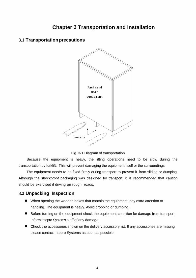
Fig. 3-1 Diagram of transportation
Because the equipment is heavy, the lifting operations need to be slow during the
transportation by forklift. This will prevent damaging the equipment itself or the surroundings.
The equipment needs to be fixed firmly during transport to prevent it from sliding or dumping.
Although the shockproof packaging was designed for transport, it is recommended that caution
should be exercised if driving on rough roads.
3.2 Unpacking Inspection When opening the wooden boxes that contain the equipment, pay extra attention to
handling. The equipment is heavy. Avoid dropping or dumping.
Before turning on the equipment check the equipment condition for damage from transport.
Inform Intepro Systems staff of any damage.
Check the accessories shown on the delivery accessory list. If any accessories are missing
please contact Intepro Systems as soon as possible.
4
3.3 Installation Environment Requirements When selecting where to install, the following should be adhered to:
1) Install the equipment indoors and maintain air flow. Try to keep the equipment air
inlet/outlet free of dust;
2) The surface on which the equipment is installed should have sufficient strength to support
the equipment and be as level as possible. T he equipment shall not shake once it is in
place;
3) The equipment adopts the incoming line and t h e outgoing line. I t is recommended to
arrange lines and cables connected externally from the cable trenches to facilitate the
installation and maintenance;
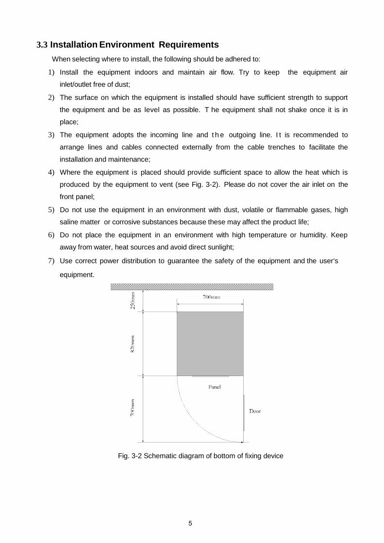
4) Where the equipment is placed should provide sufficient space to allow the heat which is
produced by the equipment to vent (see Fig. 3-2). Please do not cover the air inlet on the
front panel;
5) Do not use the equipment in an environment with dust, volatile or flammable gases, high
saline matter or corrosive substances because these may affect the product life;
6) Do not place the equipment in an environment with high temperature or humidity. Keep
away from water, heat sources and avoid direct sunlight;
7) Use correct power distribution to guarantee the safety of the equipment and the user‘s
equipment.
Fig. 3-2 Schematic diagram of bottom of fixing device
5

3.4 Description of cable connection The cable connection of the main circuit is as shown:
Fig. 3-3 Schematic diagram of wiring terminal
Before installing the equipment, all the switches are to be disconnected. The circuit cables
should be connected properly according to the above diagram.
3.5 Cable wiring 1) Use a voltmeter to confirm that there is no voltage output in the distribution lines;
2) Confirm that all o f the switches of the variable frequency power supply are in the “OFF”
position;
3) The input and output cables can be selected according to the cables recommended by Intepro
Systems. Model AFV-33030U is shown as an example in Tables 3-1 and 3-2.
Table 3-1 Reference table of input distribution cables
Machine model Input current (A)
Input live wire (mm2) Input zero line(mm2)
Input ground wire (mm2) A B C
AFV-33030U 70.8A 25mm2 25mm2 25mm2 16mm2 16mm2
Table 3-2 Reference table of output distribution cables
Machine model Output current (A)
Output live wire (mm2) Output zero line (mm2)
Output ground wire (mm2) U V W
AFV-33030U LO:83.3A
HI:41.7A 25mm2 25mm2 25mm2 25mm2 16mm2
The reference cables recommended in the above-mentioned tables are multi-core flexible copper cables. The user can select different cables according to the input and output current conditions. When the length of the input or output lines exceed 20 meters, it is recommended that the wire diameter of the cable should be doubled.
4) Properly connect the input distribution lines to the corresponding wiring terminals at the input
terminal of the equipment, and connect the output load lines to the corresponding wiring
terminals at the output terminal of the equipment.
Note: The c orresponding relationship during wiring is generally A, B and C correspond to the common yellow, green and red; the N wire must be connected properly; DO NOT operate a charged device; when the input and output wiring distance is long, it should be considered that the line voltage drops in the wires.
6

Chapter 4 Product Specifications
4.1 Technical Specifications The specifications for all of the AFV models can be found in the following tables:
Three Phase In - Three Phase Out (15~75kVA) Model AFV-33015 AFV-33020 AFV-33030 AFV-33045 AFV-33060 AFV-33075 Capacity (kVA) 15 20 30 45 60 75 Circuit Type IBGT/PWM Input Phase Three
Voltage 120V/208V, 220V/380V, OR 277V/480V Voltage range 220V/380V±15% Frequency range 47-63 Hz Power 0.9 Max Current (A) w/ full load 28.1 37.4 56.1 84.2 112.2 140.3
Output Phase Three Wave Sine Voltage Low (V) 0V-150.0V (L-N)
High (V) 150.1V-300.0V (L-N) Frequency range 45-65 Hz Optional 45-500Hz Frequency regulation 0.01% Max Current (A) High (A) 20.8 27.8 41.7 62.5 83.3 104.2
Low (A) 41.7 55.6 83.3 125.0 166.7 208.3 System Line Regulation 1
Load Regulation 1% (linear load) THD % (linear load) Efficiency 90% Response Time 2ms Crest Factor 3:1 Protection Electronic circuit trip for over/low voltage, over current, over load, over temperature, and
short circuit protection and alarm system Readings Display VFD (Touch Screen Optional)
Voltage Res.: 0.1V, Accuracy: 0.5%FS+4Counts Current Res.: 0.1A, Accuracy: 0.5%FS+4Counts Frequency Res.: 0.1Hz, Accuracy: 0.5%FS+4Counts
Control Mode
RS-232 Standard RS-485 Standard GPIB Optional
Safety Insulation Resistance 10M ohm (Tested w/ DC 500V) Voltage Resistance 1800V 10mA for 1 min (Tested w/ AC)
Environment Cooling System Fan Cooling, Front to Rear Temperature 0°C ~ 45°C Humidity 0 ~ 90% (Non-condensing) Altitude 1500m
Case No. 1 2 Weight (lb/kg) 882/400 915/415 937/425 959/435 1081/490 1158/525
Consult factory for power levels above 800kVA
Case No. Dimensions (W x D x H mm / in) 1 650 x 920 x 1248 / 25.60 x 36.22 x 49.13 2 700 x 800 x 1620 / 27.56 x 31.50 x 63.78
7

Three Phase In - Three Phase Out (100~400kVA) Model AFV-33100 AFV-33120 AFV-33150 AFV-33200 AFV-33300 AFV-33400 Capacity (kVA) 100 120 150 200 300 400 Circuit Type IBGT/PWM Input Phase Three
Voltage 120V/208V, 220V/380V, OR 277V/480V Voltage range 220V/380V±15% Frequency range 47-63 Hz Power 0.9 Max Current (A) w/ full load 187.1 224.5 280.6 374.1 561.2 748.2
Output Phase Three Wave Sine Voltage Low (V) 0V-150.0V (L-N)
High (V) 150.1V-300.0V (L-N) Frequency range 45-65 Hz Optional 45-500Hz Frequency regulation 0.01% Max Current (A)
High (A) 138.9 166.7 208.3 277.8 416.7 555.6 Low (A) 277.8 333.3 416.7 555.6 833.3 1111.1
System Line Regulation 1 Load Regulation 1% (linear load) THD % (linear load) Efficiency 90% Response Time 2ms Crest Factor 3:1 Protection Electronic circuit trip for over/low voltage, over current, over load, over temperature, and
short circuit protection and alarm system Readings Display VFD (Touch Screen Optional)
Voltage Res.: 0.1V, Accuracy: 0.5%FS+4Counts Current Res.: 0.1A, Accuracy: 0.5%FS+4Counts Frequency Res.: 0.1Hz, Accuracy: 0.5%FS+4Counts
Control Mode
RS-232 Standard RS-485 Standard GPIB Optional
Safety Insulation Resistance 10M ohm (Tested w/ DC 500V) Voltage Resistance 1800V 10mA for 1 min (Tested w/ AC)
Environment Cooling System Fan Cooling, Front to Rear Temperature 0°C ~ 45°C Humidity 0 ~ 90% (Non-condensing) Altitude 1500m
Case No. 3 4 5 Weight (lb/kg) 1579/716 1713/777 2866/1300 3087/1400 4851/2200 5512/2500
Consult factory for power levels above 800kVA
Case No. Dimensions (W x D x H mm / in) 3 940 x 820 x 1700 / 37.00 x 32.28 x 66.93 4 1100 x 940 x 1850 / 43.31 x 37.00 x 72.83 5 1400 x 1040 x 2000 / 55.12 x 40.94 x 78.74
8
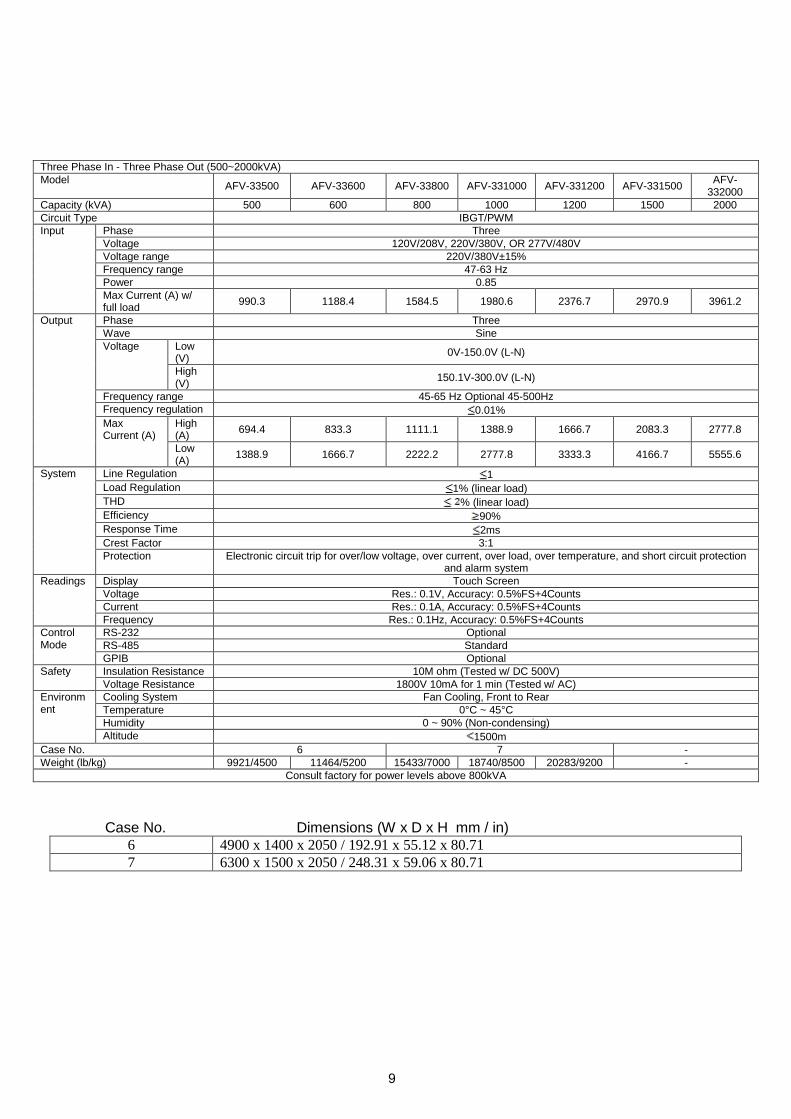
Three Phase In - Three Phase Out (500~2000kVA) Model AFV-33500 AFV-33600 AFV-33800 AFV-331000 AFV-331200 AFV-331500 AFV-
332000 Capacity (kVA) 500 600 800 1000 1200 1500 2000 Circuit Type IBGT/PWM Input Phase Three
Voltage 120V/208V, 220V/380V, OR 277V/480V Voltage range 220V/380V±15% Frequency range 47-63 Hz Power 0.85 Max Current (A) w/ full load 990.3 1188.4 1584.5 1980.6 2376.7 2970.9 3961.2
Output Phase Three Wave Sine Voltage Low
(V) 0V-150.0V (L-N)
High (V) 150.1V-300.0V (L-N)
Frequency range 45-65 Hz Optional 45-500Hz Frequency regulation 0.01% Max Current (A)
High (A) 694.4 833.3 1111.1 1388.9 1666.7 2083.3 2777.8
Low (A) 1388.9 1666.7 2222.2 2777.8 3333.3 4166.7 5555.6
System Line Regulation 1 Load Regulation 1% (linear load) THD % (linear load) Efficiency 90% Response Time 2ms Crest Factor 3:1 Protection Electronic circuit trip for over/low voltage, over current, over load, over temperature, and short circuit protection
and alarm system Readings Display Touch Screen
Voltage Res.: 0.1V, Accuracy: 0.5%FS+4Counts Current Res.: 0.1A, Accuracy: 0.5%FS+4Counts Frequency Res.: 0.1Hz, Accuracy: 0.5%FS+4Counts
Control Mode
RS-232 Optional RS-485 Standard GPIB Optional
Safety Insulation Resistance 10M ohm (Tested w/ DC 500V) Voltage Resistance 1800V 10mA for 1 min (Tested w/ AC)
Environment
Cooling System Fan Cooling, Front to Rear Temperature 0°C ~ 45°C Humidity 0 ~ 90% (Non-condensing) Altitude 1500m
Case No. 6 7 - Weight (lb/kg) 9921/4500 11464/5200 15433/7000 18740/8500 20283/9200 -
Consult factory for power levels above 800kVA
Case No. Dimensions (W x D x H mm / in) 6 4900 x 1400 x 2050 / 192.91 x 55.12 x 80.71 7 6300 x 1500 x 2050 / 248.31 x 59.06 x 80.71
9
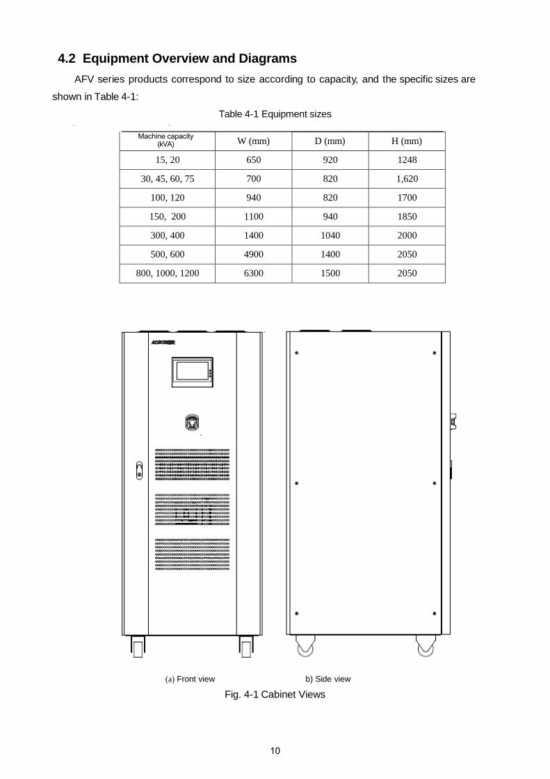
4.2 Equipment Overview and Diagrams AFV series products correspond to size according to capacity, and the specific sizes are
shown in Table 4-1:
Table 4-1 Equipment sizes
Machine capacity (kVA) W (mm) D (mm) H (mm)
15, 20 650 920 1248
30, 45, 60, 75 700 820 1,620
100, 120 940 820 1700
150, 200 1100 940 1850
300, 400 1400 1040 2000
500, 600 4900 1400 2050
800, 1000, 1200 6300 1500 2050
(a) Front view b) Side view
Fig. 4-1 Cabinet Views
10
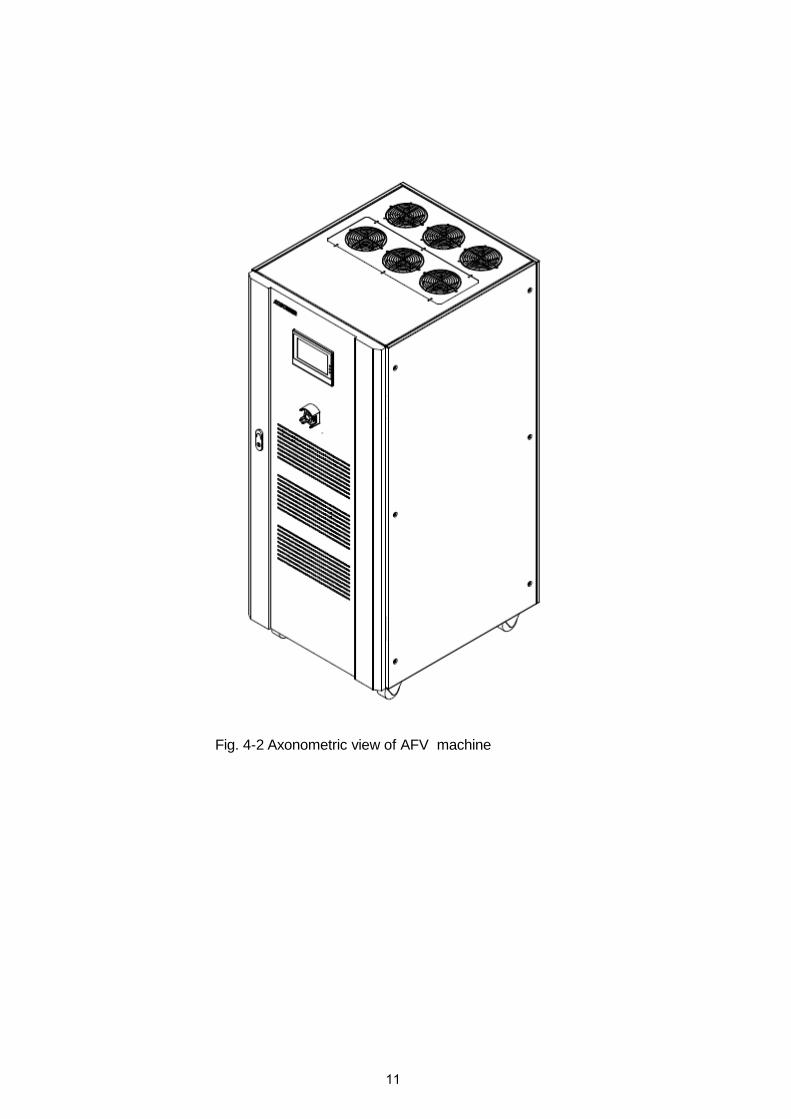
Fig. 4-2 Axonometric view of AFV machine
11

4.3 Equipment Description
① Touch screen;
Fig. 4-3 Description of complete equipment appearance
② Emergency stop button;
③ Door handle;
④ Input air switch;
⑤ Maintenance socket;
⑥ AC input terminal row;
⑦ AC output terminal row .
12

Chapter 5 Operation
5.1 Initial power-up of system
The input and output wirings should be properly connected according to the input and output
connection shown in Section 3.3. When the system is started, the main engine fan begins to
operate and the panel display screen becomes active. Also, the main interface is entered,
indicating that the start-up is normal. The parameters can then be set for the machine.
Note: If there is an external load, the load switch should be disconnected first, and the input switch should be connected (it needs to confirm whether the electric power of the input terminal row is normal before the input switch is connected).
The application interface can be entered by clicking “Application”. Users can set the
output voltage and frequency value, then press the [Operation] key when completed. Clicking
“Meas.” displays the actual output for phase voltage, current, frequency, etc.
5.2 Menu description
Application The application interface displays phase voltage, current and frequency of output terminal of
the AFV(equipment).
System In the application interface, time setting and system maintenance can be set as required.
Event Records the historical work information of the equipment.
13

5.3 Parameter setting Setting parameters correctly is a basic requirement for running the AFV equipment smoothly.
Detailed user modes are described below.
5.3.1 Start-up When the AFV equipment has been powered on the screen will show the company LOGO as in Fig. 5.1.
5-1.
Fig. 5-1 Start-up interface
The initialization interface is shown in Fig. 5-2.
Fig. 5-2 Initialization interface
14

5.3.2 User mode
Enter the main menu of the user mode. The interface display is shown in Fig. 5-3.
Fig. 5-3 Main menu of user mode
【APP】--Application: Enter the operation setting interface;
【SYSTEM】: Enter the time setting and system maintenance interface;
【EVENT】: Enter the equipment work record information table interface.
15

5.4 Application interface In the application interface, users can conduct the operations of the general mode, Step
mode, Gradual mode and Measurement mode of the equipment.
with the model specifications of the actual equipment.
5.4.1 General Mode
Fig. 5-4 Setting interface of general mode 【U Volt.】/【V Volt.】/【W Volt.】-- U-phase voltage/ V-phase voltage/ W-phase voltage:
The following three ways can be used for setting voltage at all phases:
a) Directly input the voltage value in . Click the box to pop up the keyboard, and then input the voltage value;
b) In the box of , touch left and right for adjustment;
c) Select & to conduct the setting. The variation unit is 0.1. 【Freq】-- Frequency: Doing the setting is the same as that of voltage;
【LOW】: The equipment starts to output the low voltage when selected;
【HIGH】: The equipment starts to output the high voltage when selected;
【RUN】: The equipment starts the output according to the set value when selected;
【STOP】: The equipment stops the output when selected;
【RESET】: The equipment restores the initial state when selected;
【 】: AC indicator light displays the operational state of the AC output of the equipment:
Red represents that the mode of the equipment is in the stop state, while green
represents that the mode of the equipment is running.
Note: All the product information in the operation interface of the equipment should comply
16

5.4.2 Step mode
Fig. 5-5(a) Step mode setting interface
Fig. 5-5(b) Step mode effect interface
【SETTING】: Download the set parameters;
【RUN】: The equipment starts to run the step mode when selected;
【RESET】: The equipment restores the initial state when selected;
【STOP】: The equipment stops running the step mode when selected;
& : Switch over step setting interface and step effect interface.
17
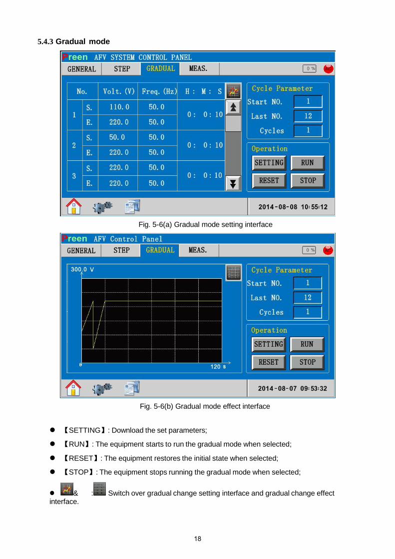
5.4.3 Gradual mode
Fig. 5-6(a) Gradual mode setting interface
Fig. 5-6(b) Gradual mode effect interface
【SETTING】: Download the set parameters;
【RUN】: The equipment starts to run the gradual mode when selected;
【RESET】: The equipment restores the initial state when selected;
【STOP】: The equipment stops running the gradual mode when selected;
& : Switch over gradual change setting interface and gradual change effect interface.
18

5.4.4 Measurement mode
Fig. 5-7 Real-time acquisition interface 【MEAS.】--Measurement: Real-time acquisition;
【STOP】: The equipment stops the output when selected;
【RESET】: The equipment restores the initial state when selected;
【RESET】: Fault reset;Fig. 5-8 Fault alarm interface
【OK】: Select to return to the real-time acquisition interface.
19
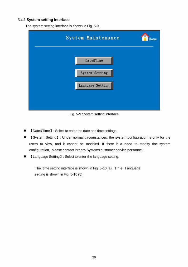
5.4.5 System setting interface The system setting interface is shown in Fig. 5-9.
Fig. 5-9 System setting interface
【Date&Time】: Select to enter the date and time settings;
【System Setting】: Under normal circumstances, the system configuration is only for the
users to view, and it cannot be modified. If there is a need to modify the system
configuration, please contact Intepro Systems customer service personnel;
【Language Setting】: Select to enter the language setting.
The time setting interface is shown in Fig. 5-10 (a). T h e l anguage
setting is shown in Fig. 5-10 (b).
20

Fig. 5-10 (a) Date&Time setting interface 【Date】/【Time】: Input the date and time of the equipment through the digital keyboard;
【Back】: Click it to back the previous interface;
【Home】: Click it to back the main interface.
Fig. 5-10 (b) Language setting interface
【简体中文】【/ 繁體中文】【/ English】: There are three language settings: Simplified Chinese,
Traditional Chinese and English;
【Back】: Click it to go back to the previous interface;
【Home】: Click it to return to the main interface.
21

5.4.6 System log
The system log interface is shown in Fig. 5-11.
Fig. 5-11 System log setting interface
【Previous】/【Next】: Browse the historical event contents; 【Clear】: Empty the system log table; 【Back】: Return to the previous menu.
22
5.5 RS485 communication 5.5.1 RS485 communication wiring
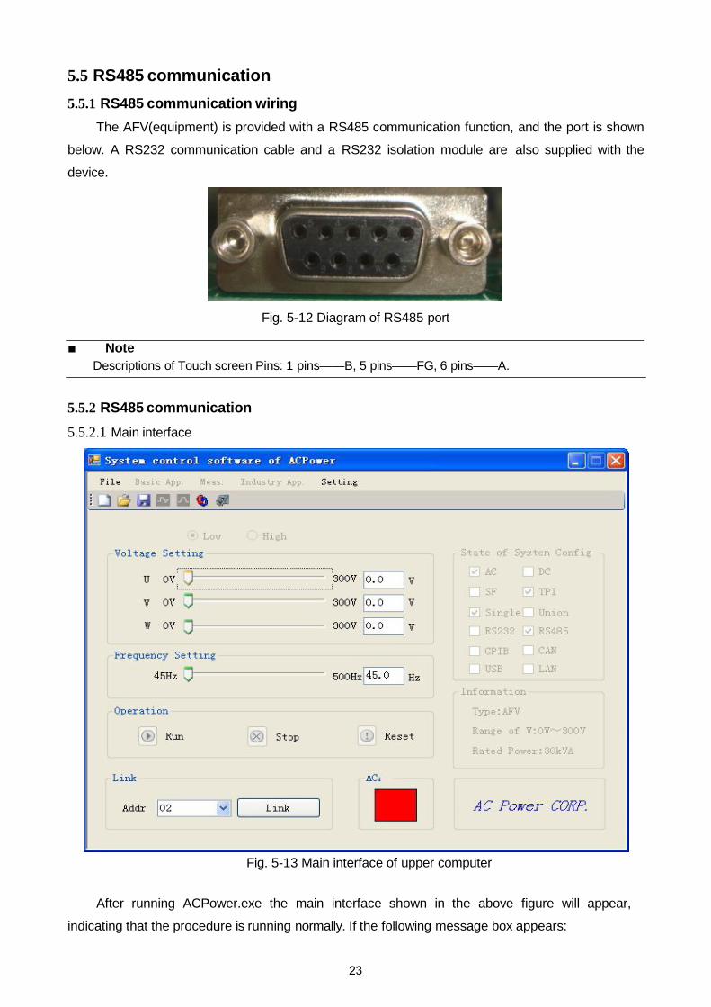
The AFV(equipment) is provided with a RS485 communication function, and the port is shown
below. A RS232 communication cable and a RS232 isolation module are also supplied with the
device.
Fig. 5-12 Diagram of RS485 port
■ NoteDescriptions of Touch screen Pins: 1 pins——B, 5 pins——FG, 6 pins——A.
5.5.2 RS485 communication
5.5.2.1 Main interface
Fig. 5-13 Main interface of upper computer
After running ACPower.exe the main interface shown in the above figure will appear,
indicating that the procedure is running normally. If the following message box appears:
23

Fig. 5-14 Files configuration message box
This message box indicates that the proper system configuration files are not found. To
correct, users should select 【Load Config】on the【File】menu, as shown in the following figure:
Fig. 5-15 File import configuration menu
Users can import the configuration files (e.g. AFV.cfg) for their power supply model f r om
the CD supplied with the variable frequency power supply. For additional inquiries please contact Intepro Systems.
【Link】: Connecting device;
【Run】: When selected the equipment starts the output according to the set value;
【Stop】: The equipment stops the output when selected;
【Reset】: The equipment restores the initial state when selected;
24

【Basic App.】-- Basic Application: Includes the Basic Application, Step and Gradual;
【Meas.】-- Measurement : Real-time Sampling;
【Industry App.】-- Industry Application;
Users will next enter the main interface. Before the【Link】operation is done with the variable
frequency power supply, make sure the controlling buttons【Run】,【Stop】, 【Reset】are
grey and in the inoperable state. The menus of Basic Application, Measurement, Industry Application and other menus are also grey and in an inoperable state.
User can select 【Link】 in the main interface to open the communication connection with the variable frequency power supply. The main interface will eliminate the grey state when the connection is successfully established, as shown in the following figure:
Fig. 5-16 Basic application
In the main interface (the system configuration state), product information and the functions
of toolbar and basic applications menu are all displayed. The information is from the imported
system configuration files and includes the max./min. value of voltage and frequency.
Only Intepro Systems can modify and update the system configuration files.
25

5.5.2.2 Step On the application interface, select the [Step] option to enter the Step function interface:
(a) Step function setting interface
(b) Step function setting interface - preview Fig. 5-17 Step function interface in remote control
26

U, V, W three-phase selection: When the independently adjustable three-phase
output functions are unavailable, this option is unavailable and appears grey;
The maximum number of user-defined data groups can be set up is 24; the maximum
number of user-defined data cycles that can be set up is 255;
[Preview] button shows a visual simulation of user-defined data;
Select the [Setting] button to download user-defined data to the AC power supply;
User-defined data will be automatically updated and saved after [Preview] button or
[Setting] button or [Run] button is selected;
【 】Status Indicator: Red indicates that the device AC / DC is stopped; green indicates
t h a t the device AC / DC is in the output state;
NOTE: User-defined data is not saved until the [Preview] button or [Setting] button or
[Run] button is pressed.
【Run】: The equipment starts to run the step mode when selected;
【Stop】: When selected the equipment stops running the step mode;
【Reset】: Selecting this restores the initial state.
27

5.5.2.3 Gradual
On the application interface, select the [Gradual] option to access the gradual function interface:
(a) Gradual function setting interface
28
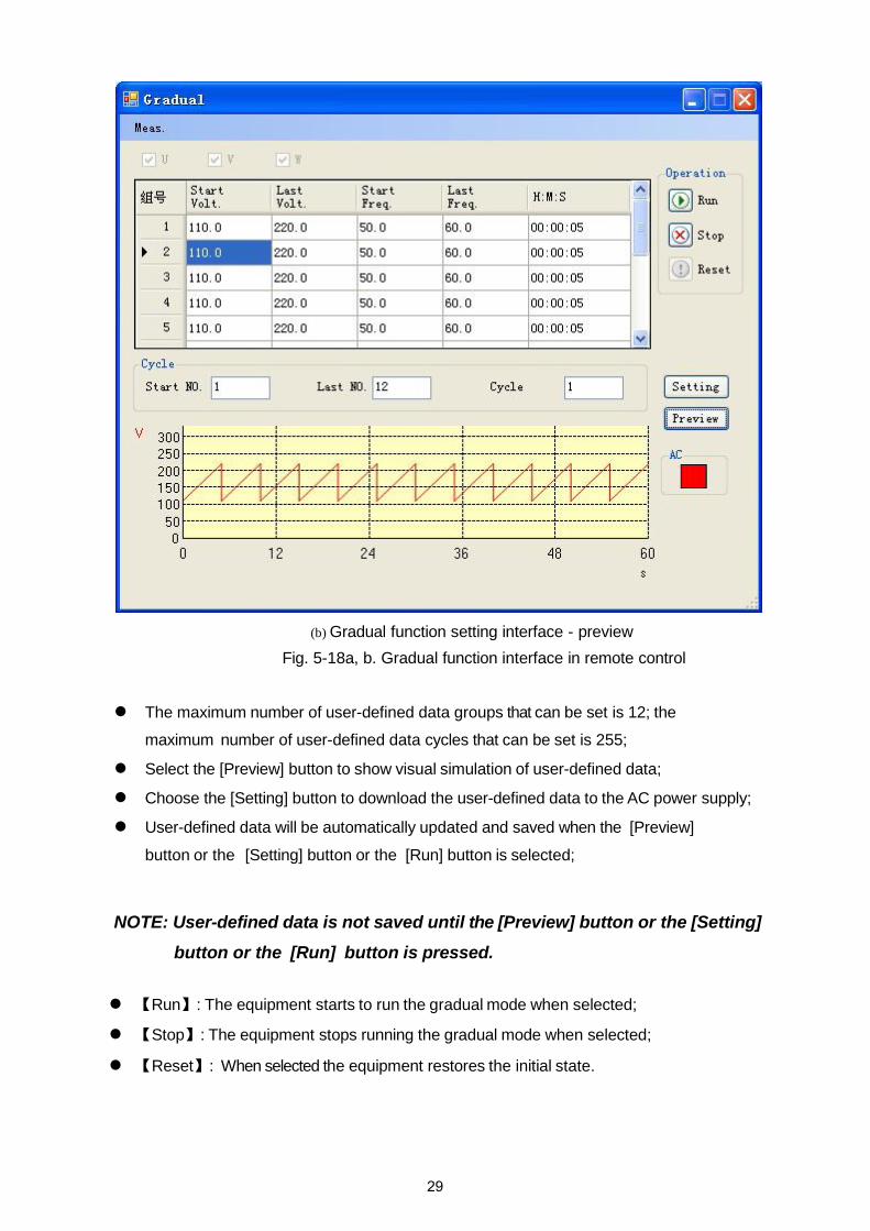
(b) Gradual function setting interface - preview Fig. 5-18a, b. Gradual function interface in remote control
The maximum number of user-defined data groups that can be set is 12; the
maximum number of user-defined data cycles that can be set is 255;
Select the [Preview] button to show visual simulation of user-defined data;
Choose the [Setting] button to download the user-defined data to the AC power supply;
User-defined data will be automatically updated and saved when the [Preview]
button or the [Setting] button or the [Run] button is selected;
NOTE: User-defined data is not saved until the [Preview] button or the [Setting] button or the [Run] button is pressed.
【Run】: The equipment starts to run the gradual mode when selected;
【Stop】: The equipment stops running the gradual mode when selected;
【Reset】: When selected the equipment restores the initial state.
29

5.5.2.4 Measurement
Fig. 5-19 Real-time Sampling
The real-time interface can be entered only when the software is running.
The sampling interval may be set within the range from 1000 to 5,000ms while the default
interval may be set to be 1,000ms;
The user can choose whether to record the real-time sampling of data and save it as log file;
The user can select which data items need to be collected real-time;
The user can control or stop the sampling procedure.
30

5.5.3 File menu
Fig. 5-20 File menu
The drop-down file menu is shown in the system control screen in the above figure.
【New】: Select to create a new system data file.
【Open】: Choose to open the existing system data file.
【Save】: Select to save the existing user settings in the current system data file.
【Load Config】: Select to import the system configuration files of the software.
Note : The default system data file of the software is syssoft.ini. This file keeps the system settings, t he application function data set by the users, and other information. It preserves the latest operational data set by the users for when the software runs the next time.
31

5.5.4 System setting
1) Language setting
Fig. 5-21 Language setting
Users can select any of three languages in Language Setting, including Simplified Chinese,
Traditional Chinese and English. After selecting the language all of the text on all of the interfaces
will switch to the selected language.
32
2) Communication setting
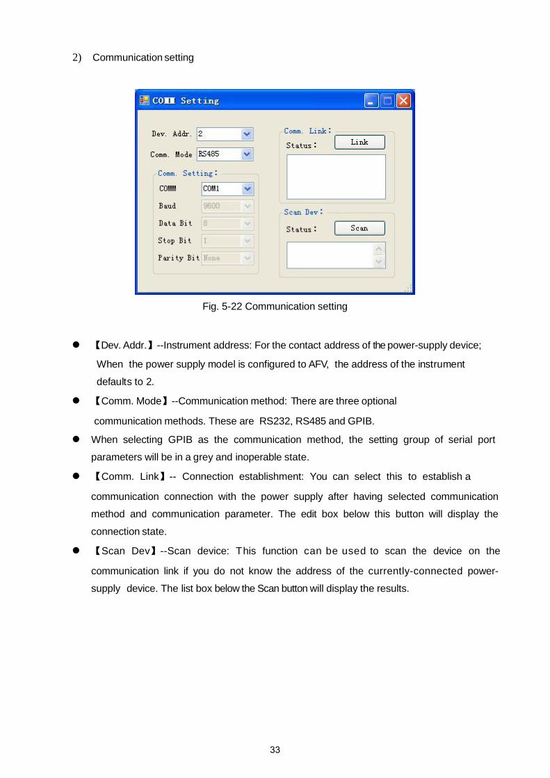
Fig. 5-22 Communication setting
【Dev. Addr.】--Instrument address: For the contact address of the power-supply device;
When the power supply model is configured to AFV, the address of the instrument
defaults to 2.
【Comm. Mode】--Communication method: There are three optional
communication methods. These are RS232, RS485 and GPIB.
When selecting GPIB as the communication method, the setting group of serial port
parameters will be in a grey and inoperable state.
【Comm. Link】-- Connection establishment: You can select this to establish a
communication connection with the power supply after having selected communication
method and communication parameter. The edit box below this button will display the
connection state.
【Scan Dev】--Scan device: This function can be used to scan the device on the
communication link if you do not know the address of the currently-connected power-
supply device. The list box below the Scan button will display the results.
33

3)On the System Control - Setting drop-down menu - select the [System Config] option to
proceed to the interface shown below in Figure 5-23:
Fig. 5-23 system configuration interface in remote control
On the system configuration interface, the user can view the product model, applications
configuration, communication interface configuration, parameter settings and power supply
hardware and software version information.
NOTE: The system configuration for the user to view under normal circumstances, can not be modified. If you need to modify the system configuration, please contact Intepro Systems.
NOTE: After the user is successfully connected via remote control, the local control interface is locked; press [local] to unlock.
34
Chapter 6 Repair and Maintenance
Ambient temperature, humidity, dust, vibration, aging and wear of components within the
equipment, and other reasons all affect the equipment and could potentially cause faults to
o c c u r . Therefore, it is necessary to conduct daily and regular repair and maintenance of the
equipment.
Only trained, authorized and qualified professionals can maintain the equipment.
6.1 Daily repair and maintenance The installation environment and the operating environment of the equipment must meet the
provisions of this user manual. During normal use, daily maintenance work should be done to
ensure a good operating environment; daily operating data, parameter setting data, parameter
change record and other data should be recorded to establish and improve equipment application
files.
Through daily maintenance and inspection, various abnormal conditions can be detected early.
T h e causes of the abnormalities and the hidden dangers of faults can then be eliminated as
soon as possible. This allows the equipment to operate normally and its service life can be
extended. Please refer to Table 6-1 for daily inspection items.
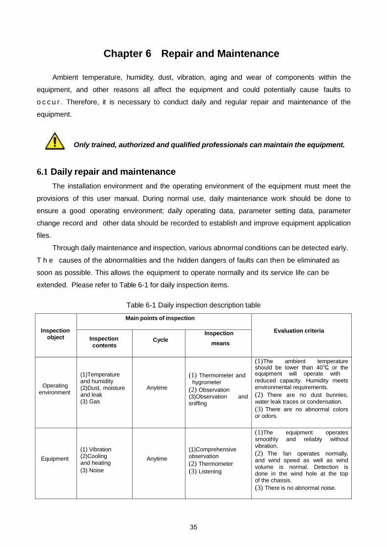
Table 6-1 Daily inspection description table
Inspection object
Main points of inspection
Evaluation criteria Inspection contents
Cycle Inspection
means
Operating environment
(1)Temperature and humidity (2)Dust, moisture and leak (3) Gas
Anytime
(1) Thermometer and hygrometer
(2) Observation (3)Observation and sniffing
(1) The ambient temperature should be lower than 40℃, or the equipment will operate with reduced capacity. Humidity meets environmental requirements. (2) There are no dust bunnies, water leak traces or condensation. (3) There are no abnormal colors or odors.
Equipment (1) Vibration (2)Cooling and heating (3) Noise
Anytime (1)Comprehensive observation (2) Thermometer (3) Listening
(1) The equipment operates smoothly and reliably without vibration. (2) The fan operates normally, and wind speed as well as wind volume is normal. Detection is done in the wind hole at the top of the chassis. (3) There is no abnormal noise.
35

Operating state
parameters
(1)Power input voltage (2)Variable frequency power output voltage (3)Variable frequency power output current (4)Internal temperature
Anytime
(1) Voltmeter (2) Rectifier-type voltmeter (3) Ammeter (4) Digimite
(1) Specifications are met. (2) Specifications are met. (3) Specifications are met. (4) Temperature rise is lower than 40℃.
6.2 Regular maintenance
Depending on the application environment, users can conduct a regular inspection of
the equipment once every three to six months.
General inspection contents:
Clean air intake filter regularly.
Note: When removing or installing the filter, there is no need to open the front door. For access only the suction canal need be removed to allow the filter to be taken out.
36
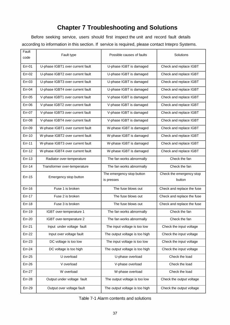
Chapter 7 Troubleshooting and Solutions Before seeking service, users should first inspect the unit and record fault details
according to information in this section. If service is required, please contact Intepro Systems. Fault
code Fault type Possible causes of faults Solutions
Err-01 U-phase IGBT1 over current fault U-phase IGBT is damaged Check and replace IGBT
Err-02 U-phase IGBT2 over current fault U-phase IGBT is damaged Check and replace IGBT
Err-03 U-phase IGBT3 over current fault U-phase IGBT is damaged Check and replace IGBT
Err-04 U-phase IGBT4 over current fault U-phase IGBT is damaged Check and replace IGBT
Err-05 V-phase IGBT1 over current fault V-phase IGBT is damaged Check and replace IGBT
Err-06 V-phase IGBT2 over current fault V-phase IGBT is damaged Check and replace IGBT
Err-07 V-phase IGBT3 over current fault V-phase IGBT is damaged Check and replace IGBT
Err-08 V-phase IGBT4 over current fault V-phase IGBT is damaged Check and replace IGBT
Err-09 W-phase IGBT1 over current fault W-phase IGBT is damaged Check and replace IGBT
Err-10 W-phase IGBT2 over current fault W-phase IGBT is damaged Check and replace IGBT
Err-11 W-phase IGBT3 over current fault W-phase IGBT is damaged Check and replace IGBT
Err-12 W-phase IGBT4 over current fault W-phase IGBT is damaged Check and replace IGBT
Err-13 Radiator over-temperature The fan works abnormally Check the fan
Err-14 Transformer over-temperature The fan works abnormally Check the fan
Err-15 Emergency stop button The emergency stop button
is presses
Check the emergency stop
button
Err-16 Fuse 1 is broken The fuse blows out Check and replace the fuse
Err-17 Fuse 2 is broken The fuse blows out Check and replace the fuse
Err-18 Fuse 3 is broken The fuse blows out Check and replace the fuse
Err-19 IGBT over-temperature 1 The fan works abnormally Check the fan
Err-20 IGBT over-temperature 2 The fan works abnormally Check the fan
Err-21 Input under voltage fault The input voltage is too low Check the input voltage
Err-22 Input over voltage fault The output voltage is too high Check the input voltage
Err-23 DC voltage is too low The input voltage is too low Check the input voltage
Err-24 DC voltage is too high The output voltage is too high Check the input voltage
Err-25 U overload U-phase overload Check the load
Err-26 V overload V-phase overload Check the load
Err-27 W overload W-phase overload Check the load
Err-28 Output under voltage fault The output voltage is too low Check the output voltage
Err-29 Output over voltage fault The output voltage is too high Check the output voltage
Table 7-1 Alarm contents and solutions
37

Chapter 8 After-Sales Service
Intepro Systems provides a full range of technical support to customers. Customers are encouraged to contact our branch office or our technical personnel when you have purchased our product.
For the details of warranty, please refer to the terms of warranty. We provide paid customization service packages at different levels, including fast response, preventive maintenance, and warranty renewal service. Please contact the local service centers of our company.
• Service TelephoneUSA: +1.714.953.2686UK/Europe: +44.1251.875600Asia: +86.755.86500020
• On-line technical service: www.InteproATE.com
• Intepro Systems America, LP14712-A Franklin AvenueTustin, CA 92780USATel: +1.714.953.2686Fax: +1.714.673.6567
38

Quality Service
Innovation
Warranty Card
Dear ,
Thanks for your support and patronage. This card is to ensure that in case the grid simulators you
have purchased (model: ____________, serial number:
fail in normal conditions of use within a year because of the process error or component
deterioration, Intepro Systems, LP. will have responsibility to provide after-sales service for free.
Please note:
The machine is required to be installed and used properly. Do not modify the structure, circuit or component.
1. If the machine has faults, please call us or pack the machine properly and indicate the faults before
sending back to our company. We will serve you as soon as possible.
2. If the warranty period expires, and the customer keeps the card, we will charge a reasonable fee
after the completion of repair.
Attn: Date:
39

40