user manual - eatoncorp.com.aupub/@electrical/documen… · user manual effective march 2011 ......
TRANSCRIPT

OPTC6 CANopen Option Board for 9000X Drive
User Manual
Effective March 2011
Supersedes November 2003

OPTC6 CANopen Option Board for 9000X Drive
OPTC6 CANopen Option Board for 9000X Drive
MN04003007E—March 2011 www.eaton.com
i
Disclaimer of Warranties and Limitation of Liability
The information, recommendations, descriptions, and safety notations in this document are based on Eaton Electrical Inc. and/or Eaton Corporation’s (“Eaton”) experience and judgment, and may not cover all contingencies. If further information is required, an Eaton sales office should be consulted.
Sale of the product shown in this literature is subject to the terms and conditions outlined in appropriate Eaton selling policies or other contractual agreement between Eaton and the purchaser.
THERE ARE NO UNDERSTANDINGS, AGREEMENTS, WARRANTIES, EXPRESSED OR IMPLIED, INCLUDING WARRANTIES OF FITNESS FOR A PARTICULAR PURPOSE OR MERCHANTABILITY, OTHER THAN THOSE SPECIFICALLY SET OUT IN ANY EXISTING CONTRACT BETWEEN THE PARTIES. ANY SUCH CONTRACT STATES THE ENTIRE OBLIGATION OF EATON. THE CONTENTS OF THIS DOCUMENT SHALL NOT BECOME PART OF OR MODIFY ANY CONTRACT BETWEEN THE PARTIES. In no event will Eaton be responsible to the purchaser or user in contract, in tort (including negligence), strict liability or otherwise for any special, indirect, incidental, or consequential damage or loss whatsoever, including but not limited to damage or loss of use of equipment, plant or power system, cost of capital, loss of power, additional expenses in the use of existing power facilities, or claims against the purchaser or user by its customers resulting from the use of the information, recommendations, and descriptions contained herein.
The information contained in this manual is subject to change without notice.

OPTC6 CANopen Option Board for 9000X Drive
ii OPTC6 CANopen Option Board for 9000X Drive
MN04003007E—March 2011 www.eaton.com
Support Services
The goal of Eaton is to ensure your greatest possible satisfaction with the operation of our products. We are dedicated to providing fast, friendly, and accurate assistance. That is why we offer you so many ways to get the support you need. Whether it’s by phone, fax, or e-mail, you can access Eaton’s support information 24 hours a day, seven days a week. Our wide range of services is listed below. You should contact your local distributor for product pricing, availability, ordering, expediting, and repairs.
Web Site
Use the Eaton Web site to find product information. You can also find information on local distributors or Eaton’s sales offices.
Web Site Address
www.eaton.com/electrical
EatonCare Customer Support Center
Call the EatonCare Support Center if you need assistance with placing an order, stock availability or proof of shipment, expediting an existing order, emergency shipments, product price information, returns other than warranty returns, and information on local distributors or sales offices. Voice: 877-ETN-CARE (877-386-2273) (8:00 a.m.–6:00 p.m. Eastern Time U.S. [UTC –5]) FAX: 800-752-8602 After-Hours Emergency: 800-543-7038 (6:00 p.m.–8:00 a.m. Eastern Time U.S. [UTC –5]) If you are in the U.S. or Canada, and have OI or PLC questions, you can take advantage of our toll-free line for technical assistance with hardware and software product selection, system design and installation, and system debugging and diagnostics. Technical support engineers are available for calls during regular business hours.
Drives Technical Resource Center
Voice: 800-322-4986 or +1 828-651-0984 (8:00 a.m.–5:00 p.m. Central Time U.S. [UTC –6]) Fax: +1 920-262-6070e-mail: [email protected]
For Customers in Europe, Contact:
Eaton Industries GmbHElectrical SectorAfter Sales ServiceHein-Moeller-Str. 7-11D-53115 BonnPhone: +49 (0) 228 6 02-3640Fax: +49 (0) 228 6 02-61400Hotline: +49 (0) 180 5 223822e-mail: [email protected]/aftersales

OPTC6 CANopen Option Board for 9000X Drive
OPTC6 CANopen Option Board for 9000X Drive
MN04003007E—March 2011 www.eaton.com
iii
Table of Contents
SAFETY
Definitions and Symbols . . . . . . . . . . . . . . . . . . . . . . . . . . . . . . . . . . . . . . . . . .
vi
Hazardous High Voltage . . . . . . . . . . . . . . . . . . . . . . . . . . . . . . . . . . . . . . . . . . .
vi
Warnings and Cautions . . . . . . . . . . . . . . . . . . . . . . . . . . . . . . . . . . . . . . . . . . .
vi
GENERAL INFORMATION
General . . . . . . . . . . . . . . . . . . . . . . . . . . . . . . . . . . . . . . . . . . . . . . . . . . . . . . . .
1
OPTC6 CANOPEN OPTION BOARD TECHNICAL DATA
General . . . . . . . . . . . . . . . . . . . . . . . . . . . . . . . . . . . . . . . . . . . . . . . . . . . . . . . .
2
CANopen Cable . . . . . . . . . . . . . . . . . . . . . . . . . . . . . . . . . . . . . . . . . . . . . . . . .
2
OPTC6 CANOPEN DESCRIPTION
CANopen. . . . . . . . . . . . . . . . . . . . . . . . . . . . . . . . . . . . . . . . . . . . . . . . . . . . . . .
3
OPTC6 CANOPEN OPTION BOARD LAYOUT AND CONNECTIONS
OPTC6 CANopen Option Board . . . . . . . . . . . . . . . . . . . . . . . . . . . . . . . . . . . . .
4
Bus Terminal Resistors . . . . . . . . . . . . . . . . . . . . . . . . . . . . . . . . . . . . . . . . . . .
4
LED Indications . . . . . . . . . . . . . . . . . . . . . . . . . . . . . . . . . . . . . . . . . . . . . . . . .
5
Connection of CANopen Bus Cable . . . . . . . . . . . . . . . . . . . . . . . . . . . . . . . . . .
6
Grounding by Clamping the Cable to the Converter Frame . . . . . . . . . . . . . . . .
6
Grounding the Bus Cable Shield Directly to the Drive Frame Usingan RC-Filter . . . . . . . . . . . . . . . . . . . . . . . . . . . . . . . . . . . . . . . . . . . . . . . . . . . .
6
Grounding the Bus Cable Shield Directly to the Frequency Converter Frame Using Jumper X1 . . . . . . . . . . . . . . . . . . . . . . . . . . . . . . . . . . . . . . . . .
7
Grounding the Bus Cable Shield Directly to the Frequency Converter Frame Using an RC-Filter . . . . . . . . . . . . . . . . . . . . . . . . . . . . . . . . . . . . . . . . .
9
INSTALLATION OF THE OPTC6 CANOPEN OPTION BOARD
Board Information Sticker . . . . . . . . . . . . . . . . . . . . . . . . . . . . . . . . . . . . . . . . .
12
COMMISSIONING
Expander Board Menu (M6) . . . . . . . . . . . . . . . . . . . . . . . . . . . . . . . . . . . . . . . .
13
OPTC6 CANopen Parameters . . . . . . . . . . . . . . . . . . . . . . . . . . . . . . . . . . . . . .
13
CANopen Status . . . . . . . . . . . . . . . . . . . . . . . . . . . . . . . . . . . . . . . . . . . . . . . .
14
OPTC6 CANOPEN 9000X DRIVE INTERFACE
CANopen Message Frame . . . . . . . . . . . . . . . . . . . . . . . . . . . . . . . . . . . . . . . . .
15
COB-ID . . . . . . . . . . . . . . . . . . . . . . . . . . . . . . . . . . . . . . . . . . . . . . . . . . . . . . . .
15
Predefined Connection Sets . . . . . . . . . . . . . . . . . . . . . . . . . . . . . . . . . . . . . . .
16
Network Management (NMT) . . . . . . . . . . . . . . . . . . . . . . . . . . . . . . . . . . . . . .
16
Process Data (PDO) . . . . . . . . . . . . . . . . . . . . . . . . . . . . . . . . . . . . . . . . . . . . . .
17
Transmission Types . . . . . . . . . . . . . . . . . . . . . . . . . . . . . . . . . . . . . . . . . . . . . .
18
Controlling the Drive via PDO Messages with Drive Profile . . . . . . . . . . . . . . .
19
State Machine . . . . . . . . . . . . . . . . . . . . . . . . . . . . . . . . . . . . . . . . . . . . . . . . . .
21
Using Manufacturer-Specific PDOs with Bypass Modes . . . . . . . . . . . . . . . . .
22
Controlling the 9000X Drive . . . . . . . . . . . . . . . . . . . . . . . . . . . . . . . . . . . . . . . .
23
Drive Monitoring . . . . . . . . . . . . . . . . . . . . . . . . . . . . . . . . . . . . . . . . . . . . . . . .
24
Anyparameter Service . . . . . . . . . . . . . . . . . . . . . . . . . . . . . . . . . . . . . . . . . . . .
25
Service Data (SDO) . . . . . . . . . . . . . . . . . . . . . . . . . . . . . . . . . . . . . . . . . . . . . .
26
Description of the Object Dictionary . . . . . . . . . . . . . . . . . . . . . . . . . . . . . . . . .
28

OPTC6 CANopen Option Board for 9000X Drive
iv OPTC6 CANopen Option Board for 9000X Drive
MN04003007E—March 2011 www.eaton.com
NODE GUARDING PROTOCOL
Node Guarding Protocol . . . . . . . . . . . . . . . . . . . . . . . . . . . . . . . . . . . . . . . . . . .
40
ELECTRONIC DATA SHEET, EDS-FILE
Electronic Data Sheet, EDS-File . . . . . . . . . . . . . . . . . . . . . . . . . . . . . . . . . . . . .
40
APPENDICES
Appendices. . . . . . . . . . . . . . . . . . . . . . . . . . . . . . . . . . . . . . . . . . . . . . . . . . . . .
41
List of Figures
OPTC6 CANopen Option Board . . . . . . . . . . . . . . . . . . . . . . . . . . . . . . . . . . . . .
4
LED Indications on the CANopen Board . . . . . . . . . . . . . . . . . . . . . . . . . . . . . .
5
Grounding the Bus Cable Shield Directly to the Drive Frame Using an RC-Filter . . . . . . . . . . . . . . . . . . . . . . . . . . . . . . . . . . . . . . . .
6
CANopen Cable . . . . . . . . . . . . . . . . . . . . . . . . . . . . . . . . . . . . . . . . . . . . . . . . .
6
Jumper X1 Positions . . . . . . . . . . . . . . . . . . . . . . . . . . . . . . . . . . . . . . . . . . . . .
7
Strip the CANopen Cable . . . . . . . . . . . . . . . . . . . . . . . . . . . . . . . . . . . . . . . . . .
7
Terminal Block . . . . . . . . . . . . . . . . . . . . . . . . . . . . . . . . . . . . . . . . . . . . . . . . . .
8
Data Cable . . . . . . . . . . . . . . . . . . . . . . . . . . . . . . . . . . . . . . . . . . . . . . . . . . . . .
8
CANopen Cable Connection . . . . . . . . . . . . . . . . . . . . . . . . . . . . . . . . . . . . . . .
8
Data Cables . . . . . . . . . . . . . . . . . . . . . . . . . . . . . . . . . . . . . . . . . . . . . . . . . . . .
8
CANopen Cables Fixed to Frame . . . . . . . . . . . . . . . . . . . . . . . . . . . . . . . . . . .
8
Grounding with RC Filter . . . . . . . . . . . . . . . . . . . . . . . . . . . . . . . . . . . . . . . . . .
9
Jumper X1 Positions . . . . . . . . . . . . . . . . . . . . . . . . . . . . . . . . . . . . . . . . . . . . .
9
Information Sticker . . . . . . . . . . . . . . . . . . . . . . . . . . . . . . . . . . . . . . . . . . . . . .
12
Changing the OPTC6 CANopen Option Board Parameters . . . . . . . . . . . . . . . .
13
DeviceNet Status . . . . . . . . . . . . . . . . . . . . . . . . . . . . . . . . . . . . . . . . . . . . . . . .
14
Function of the Internal State Machine . . . . . . . . . . . . . . . . . . . . . . . . . . . . . . .
17
State Machine Drive Sequence . . . . . . . . . . . . . . . . . . . . . . . . . . . . . . . . . . . . .
21
Reading Anyparameter . . . . . . . . . . . . . . . . . . . . . . . . . . . . . . . . . . . . . . . . . . .
25
Writing Anyparameter . . . . . . . . . . . . . . . . . . . . . . . . . . . . . . . . . . . . . . . . . . . .
25
Basic Device Control and Device Data Interface . . . . . . . . . . . . . . . . . . . . . . . .
41

OPTC6 CANopen Option Board for 9000X Drive
OPTC6 CANopen Option Board for 9000X Drive
MN04003007E—March 2011 www.eaton.com
v
List of Tables
CANopen Technical Data . . . . . . . . . . . . . . . . . . . . . . . . . . . . . . . . . . . . . . . . . .
2
Bus Length for CANopen Networks . . . . . . . . . . . . . . . . . . . . . . . . . . . . . . . . .
2
CANopen Board Status LED (A) Green . . . . . . . . . . . . . . . . . . . . . . . . . . . . . . .
5
Fieldbus Status LED (M) Green . . . . . . . . . . . . . . . . . . . . . . . . . . . . . . . . . . . . .
5
CANopen Parameters . . . . . . . . . . . . . . . . . . . . . . . . . . . . . . . . . . . . . . . . . . . .
13
CANopen Status Indications . . . . . . . . . . . . . . . . . . . . . . . . . . . . . . . . . . . . . . .
14
Drive Profile—Mode . . . . . . . . . . . . . . . . . . . . . . . . . . . . . . . . . . . . . . . . . . . . .
16
Bypass—Mode . . . . . . . . . . . . . . . . . . . . . . . . . . . . . . . . . . . . . . . . . . . . . . . . .
16
PDO Types . . . . . . . . . . . . . . . . . . . . . . . . . . . . . . . . . . . . . . . . . . . . . . . . . . . . .
17
Description of Transmission Types . . . . . . . . . . . . . . . . . . . . . . . . . . . . . . . . . .
18
Controlword Bits . . . . . . . . . . . . . . . . . . . . . . . . . . . . . . . . . . . . . . . . . . . . . . . .
23
Controlword Bits . . . . . . . . . . . . . . . . . . . . . . . . . . . . . . . . . . . . . . . . . . . . . . . .
23
nx_Speed_Reference . . . . . . . . . . . . . . . . . . . . . . . . . . . . . . . . . . . . . . . . . . . . .
23
Processdata_in1 … Processdata_in6 . . . . . . . . . . . . . . . . . . . . . . . . . . . . . . . . .
23
nx_Speed_Reference . . . . . . . . . . . . . . . . . . . . . . . . . . . . . . . . . . . . . . . . . . . . .
24
nx_Status_Word, Used Only with Bypass 2 Mode . . . . . . . . . . . . . . . . . . . . . .
24
Statusword Bit Descriptions . . . . . . . . . . . . . . . . . . . . . . . . . . . . . . . . . . . . . . .
24
Processdata_Out1 … Processdata_Out6 . . . . . . . . . . . . . . . . . . . . . . . . . . . . . .
24
Object Dictionary . . . . . . . . . . . . . . . . . . . . . . . . . . . . . . . . . . . . . . . . . . . . . . . .
26
Description of the Object Dictionary . . . . . . . . . . . . . . . . . . . . . . . . . . . . . . . . .
28
OPTC6 CANopen Option Board has the Following Items for Guarding Purposes . . . . . . . . . . . . . . . . . . . . . . . . . . . . . . . . . . . . . . . . . . . . .
40
Process Data . . . . . . . . . . . . . . . . . . . . . . . . . . . . . . . . . . . . . . . . . . . . . . . . . . .
43
Basic, Standard, Local/Remote, Multi-Step Applications . . . . . . . . . . . . . . . . . .
43
Multipurpose Control Applications . . . . . . . . . . . . . . . . . . . . . . . . . . . . . . . . . . .
43
PID Control, and Pump and Fan Control Applications . . . . . . . . . . . . . . . . . . . .
43

OPTC6 CANopen Option Board for 9000X Drive
vi OPTC6 CANopen Option Board for 9000X Drive
MN04003007E—March 2011 www.eaton.com
Safety
Definitions and Symbols
WARNING
This symbol indicates high voltage. It calls yourattention to items or operations that could be dangerousto you and other persons operating this equipment.Read the message and follow the instructions carefully.
This symbol is the “Safety Alert Symbol.” It occurs witheither of two signal words: CAUTION or WARNING, asdescribed below.
WARNING
Indicates a potentially hazardous situation that, if notavoided, can result in serious injury or death.
CAUTION
Indicates a potentially hazardous situation that, if notavoided, can result in minor to moderate injury, or seriousdamage to the product. The situation described in theCAUTION may, if not avoided, lead to serious results.Important safety measures are described in CAUTION (aswell as WARNING).
Hazardous High Voltage
WARNING
Motor control equipment and electronic controllers areconnected to hazardous line voltages. When servicingdrives and electronic controllers, there may be exposedcomponents with housings or protrusions at or aboveline potential. Extreme care should be taken to protectagainst shock.
Stand on an insulating pad and make it a habit to use onlyone hand when checking components. Always work withanother person in case an emergency occurs. Disconnectpower before checking controllers or performingmaintenance. Be sure equipment is properly grounded. Wearsafety glasses whenever working on electronic controllers orrotating machinery.
Warnings and Cautions
WARNING
Internal components and circuit boards are at highpotential when the frequency converter is connected tothe power source. This voltage is extremely dangerousand may cause death or severe injury if you come intocontact with it.
WARNING
Make sure that the frequency converter is switched offbefore an option or fieldbus board is changed or added!

General Information
OPTC6 CANopen Option Board for 9000X Drive
MN04003007E—March 2011 www.eaton.com
1
General Information
General
Eaton 9000X drives can be connected to the CANopen system using a fieldbus board. The drive can then be controlled, monitored, and programmed from the Host system.
The CANopen fieldbus board must be installed in slot E on the control board of the frequency converter. See
Page 10
for further instructions.
WARNING
Internal components and circuit boards are at highpotential when the frequency converter is connected tothe power source. This voltage is extremely dangerousand may cause death or severe injury if you come intocontact with it.
Note:
When experiencing problems with fieldbus functionalities, please contact www.eaton.com.

OPTC6 CANopen Option Board Technical Data
2 OPTC6 CANopen Option Board for 9000X Drive
MN04003007E—March 2011 www.eaton.com
OPTC6 CANopen Option Board Technical Data
General
CANopen Technical Data
CANopen Cable
According to the ISO 11898 standard, cables to be chosen for CANbus lines should have a nominal impedance of 120 ohms, and a specific line delay of nominal 5 ns/m. Line termination has to be provided through termination resistors of 120 ohms located at both ends of the line. The length-related resistance should have 70 milliohms/meter. All these mentioned AC and DC parameters are suitable for a 1 Mbit/s transmission rate.
The table below shows practical bus length for CANopen networks with less than 64 nodes.
Bus Length for CANopen Networks
Description Specification
CANopen connections Interface Open style connector (pluggable connector, 5.08 mm)
Data transfer method CAN (ISO 11898)
Transfer cable Two-wire twisted shielded cable
Electrical isolation 500 Vdc
Communications CANopen CiA DS-301
CiA DSP-402
Baud rate 10 kBaud
20 kBaud
50 kBaud
100 kBaud
125 kBaud
250 kBaud
500 kBaud
1000 kBaud
Addresses 1–127
Environment Ambient operating temperature –10°C to +55°C
Storing temperature –40°C to +60°C
Humidity <95%, no condensation allowed
Altitude Max. 1000m
Vibration 0.5G at 9–200 Hz
Safety Fulfills EN50178 standard
Baud Rate (Kbit/s) Maximum Bus Length (m) Bit Time (mS)
1000 30 1
800 50 1.25
500 100 2
250 250 4
125 500 8
50 1000 20
20 2500 50

OPTC6 CANopen Description
OPTC6 CANopen Option Board for 9000X Drive
MN04003007E—March 2011 www.eaton.com
3
OPTC6 CANopen Description
CANopen
CANopen is a networking system based on the serial bus Controller Area Network (CAN). The CANopen Communication Profile (CiA DS-301) supports both direct access to device parameters and time-critical process data communication. CANopen device profiles (CiA DS-40x) define standards for basic device functionality, while providing ample scope for additional vendor-specific device features. CANopen leashes the full power of CAN by allowing direct peer-to-peer data exchange between nodes in an organized and, if necessary, deterministic manner. The network management functions specified in CANopen simplify project design, implementation, and diagnosis by providing standard mechanisms for network startup and error management.
CANopen supports both cyclic and event-driven communication. This makes it possible to reduce the bus load to a minimum, but still maintain extremely short reaction times. High communication performance can be achieved at relatively low baud rates, thus reducing EMC problems and minimizing cable costs.
CANopen is the ideal networking system for all types of automated machinery. One of the distinguishing features of CANopen is its support for data exchange at the supervisory control level, as well as accommodating the integration of very small sensors and actuators on the same physical network. This avoids the unnecessary expense of gateways linking sensor/actuator bus systems with higher communication networks and makes CANopen particularly attractive to original equipment manufacturers.
The Device Profile Drives and Motion Control (CiA DSP-402) document represents the standardized CANopen Device Profile for digital-controlled motion products like servo controllers, frequency converters, or stepper motors. All of the above-mentioned devices use communication techniques that conform to those described in the CANopen Application Layer and Communication Profile. The starting and stopping of the drive and several mode-specific commands are executed by the state machine. The operation mode defines the behavior of the drive. The following modes are defined in this profile:
●
Homing mode
●
Profile Position mode
●
Interpolated Position mode
●
Profile Velocity mode
●
Profile Torque mode
●
Velocity mode
The OPTC6 CANopen Option Board supports the Velocity mode.

OPTC6 CANopen Option Board Layout and Connections
4 OPTC6 CANopen Option Board for 9000X Drive
MN04003007E—March 2011 www.eaton.com
OPTC6 CANopen Option Board Layout and Connections
OPTC6 CANopen Board is connected to the fieldbus through a 5-pin pluggable bus connector.
The communication with the control board of the frequency converter takes place through the standard Eaton Interface Board Connector.
OPTC6 CANopen Option Board
OPTC6 CANopen Option Board
Bus Terminal Resistors
If Eaton’s drive is the last device of the CANopen line, the bus termination must be set. Use jumper X6 (ON position see figure above), or an external resistor (120 ohms) connected to terminals 2 and 4.
AM
1
BusConnector
GroundingPlate
Jumpers InterfaceBoard Connector
2
X1
X63
4
5
Signal Connector Description
CAN_GND 1 Ground / 0V / V–
CAN_L 2 CAN_L bus line (dominant low)
(CAN_SHLD) 3 Optional CAN shield
CAN_H 4 CAN_H bus line (dominant high)
(CAN_V+) 5 —
OFFON

OPTC6 CANopen Option Board Layout and Connections
OPTC6 CANopen Option Board for 9000X Drive
MN04003007E—March 2011 www.eaton.com
5
LED Indications
The CANopen Option Board includes two LED status indicators next to the connector: Fieldbus status (M) and CANopen(A). LED N is unused.
LED Indications on the CANopen Board
CANopen Board Status LED (A) Green
Fieldbus Status LED (M) Green
LED Description Meaning
OFF Option board not activated
ON Option board in initialization state waiting for activation command from the frequency converter
Blinking fast (1 blink/s) Option board is activated and in RUN state
Option board is ready for external communication
Blinking slow (1 blink/5s) Option board is activated and in FAULT state
Internal fault of option board
LED Description Meaning
OFF Fieldbus module is waiting for parameters from the frequency converter. No external communication
ON Fieldbus module is activated. Parameters received and module activated. Module is waiting for messages from the bus
Blinking fast (1 blink/s) Module is activated and receiving messages from the bus
Blinking slow (1 blink/5s) Module is in FAULT state. No messages from Master within the watchdog time. Bus broken, cable loose, or Master offline
NAM
1
2
X1
X63
4
5
Not Used
GreenGreen

OPTC6 CANopen Option Board Layout and Connections
6 OPTC6 CANopen Option Board for 9000X Drive
MN04003007E—March 2011 www.eaton.com
Connection of CANopen Bus CableThe bus cable shield can be grounded in three different ways:
1. Clamping the cable to the frequency converter frame.
2. To the frame of the frequency converter through an RC filter.
3. Directly to the converter frame.
Note: Normally, the option board has already been installed in slot E of the control board. It is not necessary to detach the whole board for the grounding of the bus cable shield. Just detach the terminal block.
Grounding by Clamping the Cable to the Converter FrameThis method of grounding is the most effective and is especially recommended when the distances between the devices are relatively short (see Page 9, Grounding the Bus Cable Shield). In this method of grounding, the position of jumper X1 is of no importance,
Grounding the Bus Cable Shield Directly to the Drive Frame Using an RC-FilterThis method of grounding is recommended when the distance between the devices exceeds 55 yds. (50m). When the distance between the devices is long, disturbances (e.g., voltage spikes) are more likely to appear. In this grounding method, the disturbances are filtered out. Even if the ground planes of A, B, and C are different (which is very typical in construction), there is no current between them because the points do not have a ground connection.
1. Strip about 5 cm of the CANopen cable in the same way as shown below, but cut off the grey cable shield. Remember to do this for both bus cables (except for the last device).
2. Leave no more than 1 cm of the data cable outside the terminal block and strip the data cables at about 0.5 cm to fit in the terminals. See Page 7.
Note: Do this for both bus cables.
3. Insert the data cables of both CANopen cables into terminals #2 and #4. See photo of “Terminal Block” on Page 8.
4. Strip the CANopen cable at such a distance from the terminal that you can attach it to the frame with the grounding clamp. See below.
CANopen Cable
CANopenCable
A
CANopenCable
B
CANopenCable
C

OPTC6 CANopen Option Board Layout and Connections
OPTC6 CANopen Option Board for 9000X Drive MN04003007E—March 2011 www.eaton.com 7
Grounding the Bus Cable Shield Directly to the Frequency Converter Frame Using Jumper X1
1. Set jumper X1 in ON position:
Jumper X1 Positions
2. Strip about 5 cm of the CANopen cable as shown in the picture below.
Note: Do the same for both bus cables (except for the last device). However, because the grounding shall be done on one cable only, cut off the exposed part of the other grounding cable.
Strip the CANopen Cable
3. Leave no more than 1 cm of the red and green data cable outside the terminal block and strip the data cables at about 0.5 cm to fit in the terminals. See Page 8.
Note: Do this for both bus cables.
OFFON
AM
1
2
X1
X63
4
5

OPTC6 CANopen Option Board Layout and Connections
8 OPTC6 CANopen Option Board for 9000X Drive MN04003007E—March 2011 www.eaton.com
Terminal Block
Data Cable
Eaton recommends that you use an Abico connector to connect the grounding cable into the grounding terminal (#3). Insert the data cables of both CANopen cables into terminals #2 (white) and #4 (brown).
CANopen Cable Connection
Data Cables
4. Place the CANopen board into slot E of the control board (see board installation on Page 10) and fix both the CANopen cables on the frame with the clamp.
CANopen Cables Fixed to Frame
1 2 3 4 5
BW Br

OPTC6 CANopen Option Board Layout and Connections
OPTC6 CANopen Option Board for 9000X Drive MN04003007E—March 2011 www.eaton.com 9
Grounding the Bus Cable Shield Directly to the Frequency Converter Frame Using an RC-FilterEaton recommends that you do the grounding in this manner when the distance between the devices exceeds 50 meters (55 yds). When the distance between the devices is long, disturbances (for example, voltage spikes) are more likely to appear. In this grounding method, the disturbances are filtered out. Even if the ground planes of A, B, and C are different (which is very typical, for example, in construction) there is no current between them because the points do not have a ground connection.
Grounding with RC Filter
1. Set jumper X1 in the OFF position.
Jumper X1 Positions
2. Carry out the grounding in the same way as advised on Page 6.
CANopenCable
A
CANopenCable
B
CANopenCable
C
OFFON
AM
1
2
X1
X63
4
5

Installation of the OPTC6 CANopen Option Board
10 OPTC6 CANopen Option Board for 9000X Drive MN04003007E—March 2011 www.eaton.com
Installation of the OPTC6 CANopen Option Board
WARNING
NOTE: Make sure that the frequency converter isswitched off before an option or fieldbus board ischanged or added!
Step Example
1. Remove the cable cover.
2. Open the cover of the control unit
3. Install CANopen Option Board in slot E on the control board ofthe frequency converter. Make sure that the grounding plate(see right) fits tightly in the clamp.
1
2
X1
X63
4
5

Installation of the OPTC6 CANopen Option Board
OPTC6 CANopen Option Board for 9000X Drive MN04003007E—March 2011 www.eaton.com 11
Step Example
4. Make a sufficiently wide opening for your cable by cutting the grid as wide as necessary
5. Close the cover of the control unit and the cable cover.

Installation of the OPTC6 CANopen Option Board
12 OPTC6 CANopen Option Board for 9000X Drive MN04003007E—March 2011 www.eaton.com
Board Information StickerThe OPTC6 CANopen Option Board package delivered by the factory includes a sticker (shown below). Please mark the board type (1), the slot into which the board is mounted (2), and the mounting date (3) on the sticker. Finally, attach the sticker on your drive.
Information Sticker
H T / T H
Option board:in slot:
IP54 upgrade/ CollarEMC level modified: Date:....................
Date:....................
Date:....................
1
Drive modified:OPT.................A B C D E
3
2

Commissioning
OPTC6 CANopen Option Board for 9000X Drive MN04003007E—March 2011 www.eaton.com 13
Commissioning
First read “Commissioning” in 9000X User’s Manual (Document MN04001004E; please visit http://www.Eaton.com).
Note: You must select Fieldbus as the active control place, if you wish to control the frequency converter through fieldbus. See Eaton’s User’s Manual.
The OPTC6 CANopen Board is commissioned with the control keypad by giving values to appropriate parameters in menu M7 (for locating the expander board menu, see Eaton’s User’s Manual, Chapter 7).
Expander Board Menu (M6)The Expander Board Menu makes it possible for the user 1) to see what expander boards are connected to the control board and 2) to reach and edit the parameters associated with the expander board.
Enter the following menu level (G#) with the right Menu button. At this level, you can browse through slots A to E with the Browser buttons to see what expander boards are connected. On the lowermost line of the display, you also can see the number of parameter groups associated with the board.
If you press the Menu button right once, you will reach the parameter group level where there are two groups: Editable parameters and Monitored values. An additional press on the right Menu button takes you to either of these groups.
CANopen ParametersTo commission the CANopen board, enter the level P6.5.1.# from the parameters group (G6.5.1). Set desired values to all CANopen parameters.
Changing the OPTC6 CANopen Option Board Parameters
OPTC6 CANopen Parameters
Number Name Default Range Description
1 Node ID 1 1–127
2 Baud rate 6 1–10 kBaud 2–20 kBaud 3–50 kBaud 4–100 kBaud 5–125 kBaud 6 –250 kBaud7–500 kBaud8–1000 kBaud
Communication speed
3 Operate mode 1 1–Drive profile2–Bypass3–Bypass 2
Communication set selection1 = xPDO1, xPDO62 = xPDO1, xPDO21, xPDO223 = xPDO1, xPDO21, xPDO22
E:OPTC6 Expander boards
G1 G5 G1 G2
Node ID
63
Parameters
P1 P3
Node ID
63
Change Value
Confirm Change

Commissioning
14 OPTC6 CANopen Option Board for 9000X Drive MN04003007E—March 2011 www.eaton.com
Bypass mode can be used in customer-specific applications and in special applications, such as system interface.
Bypass 2 mode is used with standard applications, for example, Multicontrol application and All-in-One applications for SVX and SPX.
Bypass 2 mode is supported in the following system software versions:
● SVX00031V020
● SPX00032V017
The parameters of every device must be set before connecting to the bus, especially the parameters “NODE ID” and “BAUD RATE,” which must be the same as in the master configuration.
CANopen StatusTo see the present status of the CANopen Fieldbus, enter the CANopen Status page from Monitor menu (G7.5.2). See picture and table below.
DeviceNet Status
CANopen Status Indications
CANopen Status
0 INITIALIZING
4 STOPPED
5 OPERATIONAL
6 PRE_OPERATIONAL
7 RESET_APPLICATION
8 RESET_COMM
9 UNKNOWN
CANopen statusMonitor
V1 V1 25.0
CanOpen StatusMessage Counter

OPTC6 CANopen 9000X Drive Interface
OPTC6 CANopen Option Board for 9000X Drive MN04003007E—March 2011 www.eaton.com 15
OPTC6 CANopen 9000X Drive Interface
CANopen communication objects transmitted via the CAN network are described by services and protocols. They are classified as follows:
● The real-time data transfer is performed by the Process Data Objects (PDOs) protocol� REAL-TIME CONTROL OF THE DRIVE
● Service Data Objects (SDO) protocols provide the read and write access to entries of a device object dictionary � CONFIGURATION OF THE DRIVE, READ/WRITE DRIVE PARAMETERS
● The Network Management (NMT) protocols provide services for network initialization, error control, and device status control� START/STOP CANopen COMMUNICATION
CANopen Message Frame
SOF Start of Frame
RTR Remote Transmission Request
CTRL Control Field (i.e., Data Length)
CRC Cyclic Redundancy Check
ACK Acknowledge
EOF End of Frame
COB-ID The identification field of the CANopen-message is 11 bits.
The default identification field consists of a functional part and a module-ID part. The functional part determines the object priority. This kind of identification field allows communication between a master and 127 slaves. Broadcasting is indicated by a module-ID of zero. Function codes are determined with object dictionaries in device profiles.
SOF COB-ID RTR CTRL Data Segment CRC ACK EOF
1bit 11bit 1bit 5bit 0-8bytes 16bits 2bits 7bits
ID-Bit 10 9 8 7 6 5 4 3 2 1 0
COB-ID Function code
Module-ID

OPTC6 CANopen 9000X Drive Interface
16 OPTC6 CANopen Option Board for 9000X Drive MN04003007E—March 2011 www.eaton.com
Predefined Connection SetsOPTC6 CANopen option board has two different communication parameter sets. These sets can be selected via Operate Mode parameter from panel. Both communication sets fulfills “drives and motor control” profile described in CiA DSP-402.
Drive Profile—Mode
Bypass—Mode
Network Management (NMT)The CANopen network management is node-oriented and follows a master/slave structure. It requires one device in the network, which fulfills the function of the NMT master. The other nodes are NMT slaves.
The CANopen NMT slave devices implement a state machine, see illustration on Page 17, after power on a node initializes and transits to the “Pre-operational State.” In this state, communication across SDO channels is possible for node configuration, but not yet across PDOs. With the NMT message “Start Remote Node,” a selected node or any nodes on the network can be set into the “operational state.” In this state, also the exchange of data by means of PDOs is possible. With enabling the operation of all nodes of a network at the same time, a coordinated operation of the communicating system is secured (DS301).
To set the OPTC6 CANopen Option Board to the “operational state” the following message must be sent:
Message: Start_Remote_NodeMaster to slave (1)
Object Function Code (Binary) COB-ID Communication Parameter at Index
NMT message 0000 0x0000 —
Sync message 0001 0x0080 0x1005
Time–stamp–message 0001 0x0100 —
PDO1, process data objects (tx) 0011 0x0180 +Node 0x1800
PDO1, process data objects (rx) 0100 0x0200 +Node 0x1400
PDO6, process data objects (tx) 0101 0x0280 +Node 0x1801
PDO6, process data objects (rx) 0110 0x0300 +Node 0x1401
SDO, service data objects (tx) 1011 0x0580 +Node —
SDO, service data objects (rx) 1100 0x0600 +Node —
Node guarding 1110 0x0700 +Node (0x100E)
Object Function Code (Binary) COB-ID Communication Parameter at Index
NMT message 0000 0x0000 —
Sync message 0001 0x0080 0x1005
Time–stamp–message 0010 0x0100 —
PDO1, process data objects (tx) 0011 0x0180 +Node 0x1800
PDO1, process data objects (rx) 0100 0x0200 +Node 0x1400
PDO21, process data objects (tx) 0111 0x0380 +Node 0x1814
PDO21, process data objects (rx) 1000 0x0400 +Node 0x1414
PDO22, process data objects (tx) 1001 0x0480 +Node 0x1815
PDO22, process data objects (rx) 1010 0x0500 +Node 0x1415
SDO, service data objects (tx) 1011 0x0580 +Node —
SDO, service data objects (rx) 1100 0x0600 +Node —
Node guarding 1110 0x0700 +Node (0x100E)
Header Data
ID RTR Len 1 = CS 2 = Node ID 3 4 5 6 7 8
0000 0 2 01 01

OPTC6 CANopen 9000X Drive Interface
OPTC6 CANopen Option Board for 9000X Drive MN04003007E—March 2011 www.eaton.com 17
Function of the Internal State Machine
Process Data (PDO)The real-time data transfer is performed by means of “process data objects” (PDO). The transfer of PDOs is performed with no protocol overhead. Process data is time-critical data used for control of the drive and for monitor status of the drive. Transmit PDOs support several transmission modes, which are cyclic, acyclic, synchronous, asynchronous, and RTR only mode. Most PDOs support also event timer for transmitting PDOs. TPDO1 is an exception that is defined for asyncronous only operation. Receive PDOs support only asyncronous transmission mode (event driven). Eaton CANopen Option Board uses eight types of PDOs as follows:
PDO Types
Note: Manufacturer-specific PDOs (TPDO21/RPDO21/TPDO22/RPDO22) consist of application-specific process data. See appendix for contents of these process datas in different applications. See Page 22 (Using Manufacturer-Specific PDOs with Bypass Modes) or a specific application manual.
Note: All Tx objects are event-driven by default. (Message is sent out if one or several values within the message change.)
Change Message/Event Command Specifier (CS)
1 Start remote node CS = 1
2 Stop remote node CS = 2
3 Enter pre-operational state CS = 128
4 Reset node CS = 129
5 Reset communication CS = 130
6 Initialization finished Automatic
PowerOn
5
2
4
1
6
1
Initialization
3
3
2
Pre-operational
Operational
Prepared
PDO Type
Mapped Data
Mapped Data
Mapped Data
Mapped Data Cyclic Acyclic Synchronous
Asynchronous (Default)
RTR Only Mode
Event Timer
TPDO1 statusword — — — x
TPDO6 statusword vl_control_effort — — X X X x X X
TPDO21 nx_status_word nx_actual_speed process_data_out1 process_data_out2 X X X x X X
TPDO22 process_data_out3 process_data_out4 process_data_out5 process_data_out6 X X X x X X
RPDO1 controlword — — — x
RPDO6 controlword vl_target_velocity — — x
RPDO21 nx_control_word nx_speed_reference process_data_in1 process_data_in2 x
RPDO22 process_data_in3 process_data_in4 process_data_in5 process_data_in6 x

OPTC6 CANopen 9000X Drive Interface
18 OPTC6 CANopen Option Board for 9000X Drive MN04003007E—March 2011 www.eaton.com
Transmission Types
Description of Transmission Types
Synchronous (transmission types 0–240 and 252) means that the transmission of the PDO shall be related to the SYNC object. Preferably, the devices use the SYNC as a trigger to output or to actuate based on the previous synchronous Receive PDO, respectively, to update the data transmitted at the following synchronous Transmit PDO. Asynchronous means that the transmission of the PDO is not related to the SYNC object. A zero transmission type means that the message shall be transmitted synchronously with the SYNC object, but not periodically. A value between 1 and 240 means that the PDO is transferred synchronously and cyclically. The transmission type indicating the number of SYNC is necessary to trigger PDO transmissions. Receive PDOs are always triggered by the following SYNC upon reception of data independent of the transmission types 0–240.
The transmission types 252 and 253 mean that the PDO is only transmitted on remote transmission request. At transmission type 252, the data is updated (but not sent) immediately after reception of the SYNC object. At transmission type 253, the data is updated at the reception of the remote transmission request (hardware and software restrictions may apply). These values are only possible for TPDOs. For TPDOs, transmission type 254 means that the application event is manufacturer- specific (manufacturer-specific part of the Object Dictionary); transmission type 255 means that the application event is defined in the device profile. RPDOs with that type trigger the update of the mapped data with the reception. PDOs sub-index 3h contains the inhibit time. This time is a minimum interval for PDO transmission. The value is defined as multiple of 100 ms. It is not allowed to change the value while the PDO exists (bit 31 of sub-index 1 is 0).
In mode 254/255, an event time can be additionally used for TPDO. If an event timer exists for a TPDO (value not equal to 0), the elapsed timer is considered to be an event. The event timer elapses as a multiple of 1 ms of the entry in sub-index 5h of the TPDO. This event will cause the transmission of this TPDO in addition to otherwise defined events. The occurence of the events set the timer. Independent of the transmission type, the RPDO event timer is used to recognize the expiration of the RPDO.
Transmission Type
PDO Transmission
Cyclic Acyclic Synchronous Asynchronous RTR Only
0 X X
1–240 X X
241–251 —Reserved—
252 X X
253 X X
254 X
255 X

OPTC6 CANopen 9000X Drive Interface
OPTC6 CANopen Option Board for 9000X Drive MN04003007E—March 2011 www.eaton.com 19
Controlling the Drive via PDO Messages with Drive Profile
PDO1 RxMaster to slave (1)
PDO1 TxSlave (1) to master
PDO6 RxMaster to slave (1)
PDO6 TxSlave (1) to master
The state of the drive can be controlled by the controlword. The state of the drive is shown in the statusword.
The state machine describes the device status and the possible control sequency of the drive.
Header Data
ID RTR Len 1 2 3 4 5 6 7 8
0x201 0 2 controlword — — — — — —
Header Data
ID RTR Len 1 2 3 4 5 6 7 8
0x181 0 2 statusword — — — — — —
Header Data
ID RTR Len 1 2 3 4 5 6 7 8
0x301 0 4 controlword vl_target_velocity — — — —
Header Data
ID RTR Len 1 2 3 4 5 6 7 8
0x281 0 4 statusword vl_control_effort — — — —
Controlword Statusword
Bit Name Bit Name
0 Switch ON 0 Ready to Switch ON
1 Disable Voltage 1 Switched ON
2 Quick Stop 2 Operation Enable
3 Enable Operation 3 Fault
4 Operation Mode Specific 4 Voltage Disable
5 Operation Mode Specific 5 Quick Stop
6 Operation Mode Specific 6 Swich ON Disable
7 Reset Fault 7 Warning
8 Halt 8 Manufacturer Specific
9 Reserved 9 Remote
10 Reserved 10 Target Reached
11 Manufacturer Specific 11 Internal Limit Active
12 Manufacturer Specific 12 Operation Mode Specific
13 Manufacturer Specific 13 Operation Mode Specific
14 Manufacturer Specific 14 Manufacturer Specific
15 Manufacturer Specific 15 Manufacturer Specific

OPTC6 CANopen 9000X Drive Interface
20 OPTC6 CANopen Option Board for 9000X Drive MN04003007E—March 2011 www.eaton.com
By using a controlword, the drive can be controlled as follows:
vl_target_velocity
● The vl_target_velocity is the required speed reference to the frequency converter
● The unit is rpm
vl_control_effort
● The vl_control_effort is the actual speed of the motor
● The unit is rpm
Command Controlword Description
Prepare READY 0006hex Set state machine to “Ready To Switch ON” state
Prepare RUN 0007hex Set state machine to “Switched ON” state
RUN 000Fhex Start motor if “Fieldbus” is the active control place
STOP 0007hex Stop motor
FAULT RESET (step 1)FAULT RESET (step 2)
Bit 7 = 0Bit 7 = 1
Rising edge to bit 7

OPTC6 CANopen 9000X Drive Interface
OPTC6 CANopen Option Board for 9000X Drive MN04003007E—March 2011 www.eaton.com 21
State MachineThe state machine describes the device status and the possible control sequence of the drive. The state transitions can be generated by using “controlword.” The “statusword” parameter indicates the current status of the state machine. The modes INIT, STOP, RUN, and FAULT correspond to the actual mode of the drive.
SW = Statusword
CW = Controlword word
State Machine Drive Sequence
Reset MalfunctionCW: 0000h
CW: 0080h
Power ON
Not Ready to Switch OnINIT
SW:xx00h
Automatic
CW: 000Dh
Automatic Automatic
CW: 0006h CW: 0002h CW: 0003h
CW: 0007h CW: 0006h
Ready to Switch OnSTOP
SW:xx21h
Switch On DisabledSTOP
SW:xx40hor xx60h
CW: 0006h
Malfunction Reaction ActiveFAULT
SW:xxxFhor xx2Fh
MalfunctionFAULT
SW:xx08hor xx28h
CW: 000Fh CW: 0007h
CW: 0002h
Switched OnSTOP
SW:xx23h
Operation EnabledRUN
SW:xx27h
Quick Stop ActiveSTOP
SW:xx07h
Fault
OPTC6 CANopen 9000X Drive Interface
22 OPTC6 CANopen Option Board for 9000X Drive MN04003007E—March 2011 www.eaton.com
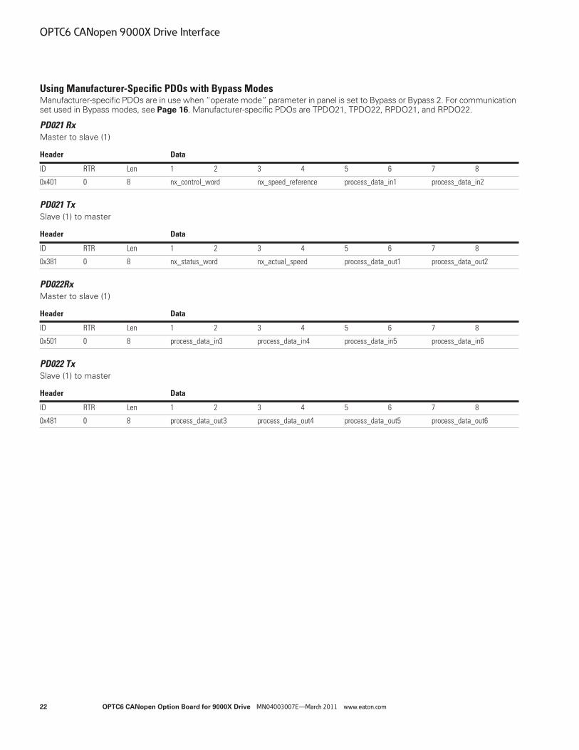
Using Manufacturer-Specific PDOs with Bypass ModesManufacturer-specific PDOs are in use when “operate mode” parameter in panel is set to Bypass or Bypass 2. For communication set used in Bypass modes, see Page 16. Manufacturer-specific PDOs are TPDO21, TPDO22, RPDO21, and RPDO22.
PD021 RxMaster to slave (1)
PD021 TxSlave (1) to master
PD022RxMaster to slave (1)
PD022 TxSlave (1) to master
Header Data
ID RTR Len 1 2 3 4 5 6 7 8
0x401 0 8 nx_control_word nx_speed_reference process_data_in1 process_data_in2
Header Data
ID RTR Len 1 2 3 4 5 6 7 8
0x381 0 8 nx_status_word nx_actual_speed process_data_out1 process_data_out2
Header Data
ID RTR Len 1 2 3 4 5 6 7 8
0x501 0 8 process_data_in3 process_data_in4 process_data_in5 process_data_in6
Header Data
ID RTR Len 1 2 3 4 5 6 7 8
0x481 0 8 process_data_out3 process_data_out4 process_data_out5 process_data_out6

OPTC6 CANopen 9000X Drive Interface
OPTC6 CANopen Option Board for 9000X Drive MN04003007E—March 2011 www.eaton.com 23
Controlling the 9000X DriveNote: Some 9000X drive applications may use “Bypass mode” for an enhanced implementation of “Velocity mode”
rather than for a manufacturer-specific interface. Please refer to the specific application manual for details.
The Reference to the drive can be set also via manufacturer-specific process data object 21 (rx) when option board is set to Bypass or Bypass 2. In the application, the value is scaled in percentage of frequency area between the set minimum and maximum frequencies.
nx_control_word, used only with Bypass 2 mode. When Bypass mode is used, check more detailed controlword in the application manual.
Controlword Bits
In 9000X drive applications, the first three bits of the controlword are used to control the frequency converter. However, you can customize the content of the controlword for your own applications because the controlword is sent to the frequency converter as such.
Controlword Bits
nx_Speed_Reference
This is the Reference 1 to the frequency converter, used normally as speed reference. The allowed scaling is –10000 to 10000. In the application, the value is scaled in percentage of the frequency area between the set minimum and maximum frequencies.
Processdata_in1 … Processdata_in6
These are application-specific process data. See Appendix C for content of these process data in different applications.
15 14 13 12 11 10 9 8 7 6 5 4 3 2 1 0
— — — — — — — — — — — — — RST DIR RUN
Bit Description
Value = 0 Value = 1
0 Run Stop
1 Clockwise Counterclockwise
2 Rising edge of this bit will reset active fault
3–15 Not in use Not in use
15 14 13 12 11 10 9 8 7 6 5 4 3 2 1 0
MSB — — — — — — — — — — — — — — LSB
15 14 13 12 11 10 9 8 7 6 5 4 3 2 1 0
MSB — — — — — — — — — — — — — — LSB

OPTC6 CANopen 9000X Drive Interface
24 OPTC6 CANopen Option Board for 9000X Drive MN04003007E—March 2011 www.eaton.com
Drive MonitoringSeveral drive actual values/parameters can be monitored by using manufacturer-specific PDOs.
nx_Speed_Reference
This is the reference 1 to the frequency converter, used normally as speed reference. The allowed scaling is 0 to 10000. In the application, the value is scaled in percentage of the frequency area between set minimum and maximum frequency.
nx_Status_Word, Used Only with Bypass 2 Mode
Note: When Bypass mode is used, check more detailed statusword in the application manual.
Information about the status of the device and messages is indicated in the statusword. The statusword is composed of 16 bits that have the following meanings.
Statusword Bit Descriptions
Processdata_Out1 … Processdata_Out6
These are application-specific process data. See Appendix C for content of these process data in different applications.
15 14 13 12 11 10 9 8 7 6 5 4 3 2 1 0
MSB — — — — — — — — — — — — — — LSB
15 14 13 12 11 10 9 8 7 6 5 4 3 2 1 0
— — — — — UVFS DDIR TCSPDL FR Z AREF W FLT DIR RUN RDY
Bit Description
Value = 0 Value = 1
0 Not Ready Ready
1 STOP RUN
2 Clockwise Counterclockwise
3 — Faulted
4 — Warning
5 Ref. frequency not reached Ref. Frequency reached
6 — Motor is running at zero speed
7 Flux Ready Flux Not Ready
8 TC Speed Limit Active (depends on drive model) TC Speed Limit Not Active (depends on drive model)
9 Detected Encoder Direction Clockwise (depends on drive model)
Encoder Direction Counterclockwise (depends on drive model)
10 UV Fast Stop Active (depends on drive model) UV Fast Stop Not Active (depends on drive model)
11–15 Not in use Not in use
15 14 13 12 11 10 9 8 7 6 5 4 3 2 1 0
MSB — — — — — — — — — — — — — — LSB

OPTC6 CANopen 9000X Drive Interface
OPTC6 CANopen Option Board for 9000X Drive MN04003007E—March 2011 www.eaton.com 25
Anyparameter ServiceSDO protocol can be used to read any parameter or actual value, and write any parameter from drive. These parameters are read from drive with its ID number specified in user manual. There are three index in the object dictionary as follows for anyparameter service.
Reading AnyparameterWriting new value to index 2000 will trigger read event, while read is in process index 2001 is zero. Read event will return value to index 2001. If read is a success, status will get the value of ID. If read fails, status will get value 0xFFFF (dec 65535).
Writing AnyparameterWhen new ID and value is written to index 2002, a write event will be triggered. Index 2002 value will remain as long as writing is processed (normal SDO/PDO operation during this time). If write is a success, index 2002 ID and value will be cleared and new write is possible. If write fails, ID will clamp to 0xFFFF and value zero.
Reading Anyparameter
Writing Anyparameter
Index Description Size Type Hi 16b Low 16b
2000 AnyparameterReadID U16 RW - Read ID
2001 AnyparameterReadValue U32 RO Status Value
2002 AnyparameterWrite U32 RW ID Write Value
Index 2000
16bi
0x0066
Read
Index 2001 0x0066 0x0032
Statu
Write ID with SDO
Value
100ms delay for read event
Read value with SDOprotocol0xFFFF 0x0000 = Fail
ID Value =
OK
•
•
•
Index 2002
16b
ID
Index 2002 0x0000 0x0000
Status
Write ID and value withSDO protocol
100ms delay for write event
Read write eventstatus0x0000 0x0000 = OK,0xFFF 0x0000 = Fail0x0066 0x003c = In
•
•
•
0x0066 0x003C
16bi
Value
16b 16bi

OPTC6 CANopen 9000X Drive Interface
26 OPTC6 CANopen Option Board for 9000X Drive MN04003007E—March 2011 www.eaton.com
Service Data (SDO)With service data objects (SDOs), the access to entries of a device object dictionary is provided. Via SDO, all items from object dictionary can be read/written.
SDOs are normally used for device configuration such as setting device parameters. They are also used to define the type and format of information communicated using the process data objects. CANopen Configuration tools with EDS-files can be used for that purpose. The construction and the method of operation of the SDOs can be found in the CANopen (DS301) Communication Profile document. Appendix B consists of a short description of the SDOs used with Eaton CANopen Option Board.
Object Dictionary
Index
Name Type Attr.hex dec
1000 4096 device_type Unsigned32 CO
1001 4097 error_register Unsigned8 RO
1003 4099 pre defined error field Unsigned32 RO
1005 4101 cob-id sync message Unsigned32 RO
100C 4108 guard_time Unsigned32 RW
100D 4109 life_time_factor Unsigned32 RW
1018 4120 Identity Object Identity
1200 4608 1st_server_SDO_parameter SDOParameter
1400 5120 1st_receive_PDO_parameter PDOCommPar
1405 5125 6st_receive_PDO_parameter PDOCommPar
1414 5140 21st_receive_PDO_parameter PDOCommPar
1415 5141 22st_receive_PDO_parameter PDOCommPar
1600 5632 1st_receive_PDO_mapping PDOMapping
1605 5637 6st_receive_PDO_mapping PDOMapping
1614 5652 21st_receive_PDO_mapping PDOMapping
1615 5653 22st_receive_PDO_mapping PDOMapping
1800 6144 1st_transmit_PDO_parameter PDOCommPar
1805 6149 6nd_transmit_PDO_parameter PDOCommPar
1814 6164 21nd_transmit_PDO_parameter PDOCommPar
1815 6165 22nd_transmit_PDO_parameter PDOCommPar
1A00 6656 1st_transmit_PDO_mapping PDOMapping
1A05 6661 6st_transmit_PDO_mapping PDOMapping
1A14 6676 21st_transmit_PDO_mapping PDOMapping
1A15 6677 22st_transmit_PDO_mapping PDOMapping
2000 8192 AnyParameterReadID Integer16 RW
2001 8193 AnyParameterReadValue Integer32 RO
2002 8194 AnyParameterWrite Integer32 RW
2003 8195 nx_current_percentage Integer16 RO
2004 8196 nx_torque_percentage Integer16 RO
2063 8291 nx_fault_code Integer16 RO
27D1 10193 NX controlword Integer16 RW
27D3 10195 NX speed reference Integer16 RW

OPTC6 CANopen 9000X Drive Interface
OPTC6 CANopen Option Board for 9000X Drive MN04003007E—March 2011 www.eaton.com 27
Object Dictionary, continued
Index
Name Type Attr.hex dec
27D4 10196 Process data in1 Integer16 RW
27D5 10197 Process data in2 Integer16 RW
27D6 10198 Process data in3 Integer16 RW
27D7 10199 Process data in4 Integer16 RW
27D8 10200 Process data in5 Integer16 RW
27D9 10201 Process data in6 Integer16 RW
2836 10294 NX status word Integer16 RO
2838 10296 NX actual speed Integer16 RO
2839 10297 Process data out1 Integer16 RO
283A 10298 Process data out2 Integer16 RO
283B 10299 Process data out3 Integer16 RO
283C 10300 Process data out4 Integer16 RO
283D 10301 Process data out5 Integer16 RO
283E 10302 Process data out6 Integer16 RO
6040 24640 controlword Unsigned16 RW
6041 24641 statusword Unsigned16 RO
6042 24642 vl_target_velocity Integer16 RW
6043 24643 vl_velocity_demand Integer16 RO
6044 24644 vl_control_effort Integer16 RO
6046 24646 vl_velocity_min_max_amount Unsigned32 RW
6048 24648 vl_velocity_acceleration Ramp RW
6049 24649 vl_velocity_deceleration Ramp RW
604A 24650 vl_velocity_quick_stop Ramp RW
604E 24654 vl_velocity_reference Unsigned32 RW
6060 24672 modes_of_operation Integer8 RO
6061 24673 modes_of_operation_display Integer8 RO

OPTC6 CANopen 9000X Drive Interface
28 OPTC6 CANopen Option Board for 9000X Drive MN04003007E—March 2011 www.eaton.com
Description of the Object Dictionary Abbreviations
ro read only
wo write only
rw read write
co constant
bool Boolean
i8 Integer8
i16 Integer8
i32 Integer8
u8 Unsigned8
u16 Unsigned16
u32 Unsigned32
float Floating Point
Description of the Object Dictionary
Index (hex) Sub-Index NameDefault Min. Max.
Type Attr. Descriptions
General Parameters
1000 00 Device Type 0x000101920x000000000xFFFFFFFF
u32co
The device type specifies the kind of device. The lower 16 bits contain the device profile number and the upper 16 bits contain additional information.
1001 00 Error Register 0x000x000xFF
u8ro
The error register is a field of 8 bits, each for a certain error type. If an error occurs, the bit has to be set.Bit Meaning0 generic error1 current2 voltage3 temperature4 communication error (overrun, error state)5 device profile specific6 reserved7 manufacturer specific
1003 Pre-defined Error Field This object holds errors that have occurred on the device and have been signaled via Emergency Object. It is an error history. Writing value 0 to sub-index 0 deletes the entire error history.
00 Number of Errors 0x00000x00000x00FE
u8rw
01 Standard Error Field 0x00000000 0x00000000 0xFFFFFFFF
u32 ro
02 Standard Error Field 0x00000000 0x00000000 0xFFFFFFFF
u32 ro
03 Standard Error Field 0x00000000 0x00000000 0xFFFFFFFF
u32 ro

OPTC6 CANopen 9000X Drive Interface
OPTC6 CANopen Option Board for 9000X Drive MN04003007E—March 2011 www.eaton.com 29
Description of the Object Dictionary, continued
Index (hex) Sub-Index NameDefault Min. Max.
Type Attr. Descriptions
General Parameters, continued
1003 04 Standard Error Field 0x00000000 0x00000000 0xFFFFFFFF
u32 ro
05 Standard Error Field 0x00000000 0x00000000 0xFFFFFFFF
u32 ro
06 Standard Error Field 0x00000000 0x00000000 0xFFFFFFFF
u32 ro
07 Standard Error Field 0x00000000 0x00000000 0xFFFFFFFF
u32 ro
08 Standard Error Field 0x00000000 0x00000000 0xFFFFFFFF
u32 ro
09 Standard Error Field 0x00000000 0x00000000 0xFFFFFFFF
u32 ro
0A Standard Error Field 0x00000000 0x00000000 0xFFFFFFFF
u32 ro
1005 00 COB-ID sync message 0x800000800x000000010xFFFFFFFF
u32 ro
COB-ID used for syncronize PDO messages
100C 00 Guard Time 0x03E80x00000xFFFF
u16 rw
This entry contains the guard time in milliseconds. It is 0 if not used. Unit: ms
100D 00 Life Time Factor 0x020x000xFF
u8 rw
The life time factor multiplied with the guard time gives the life time for the device. It is 0 if not used.
1018 Identity Object This object contains general information about the device.
00 Number of entries 0x40x10x4
u8 ro
01 Vendor ID 0x00000090 0x0 0xFFFFFFFF
u32 ro
Sub-index 1 contains a unique value allocated to each manufacturer.
02 Product Code 0x00000119 0x0 0xFFFFFFFF
u32 ro
Sub-index 2 identifies the manufacturer-specific product code (device version).
03 Revision number 0x00000001 0x0 0xFFFFFFFF
u32 ro
Sub-index 3 contains the revision number. Bit 31–16 is the major revision number and bit 15–0 the minor revision number.
04 Serial number 0x00x00xFFFFFFFF
u32 ro
Sub-index 4 identified a manufacturer-specific serial number.

OPTC6 CANopen 9000X Drive Interface
30 OPTC6 CANopen Option Board for 9000X Drive MN04003007E—March 2011 www.eaton.com
Description of the Object Dictionary, continued
Index (hex) Sub-Index NameDefault Min. Max.
Type Attr. Descriptions
Server SDO Parameters
1200 Server SDO Parameter The object contains the parameters for the SDOs for which the device is the server.
00 Number of Entries 0x02 0x02 0x02
u8 ro
01 COB-ID Client –> Server 0x600+NodeID 0x00000601 0xFFFFFFFF
u32 ro
02 COB-ID Server –> Client 0x580+NodeID 0x00000581 0xFFFFFFFF
u32 ro
Receive PDO Communication Parameters
1400 Receive PDO1 Communication Parameter
It contains the communication parameters of the first PDO that the device is able to receive.
00 Number of Entries 0x02 0x02 0x05
U8 ro
Sub-index 0 contains the number of PDO-parameters implemented.
01 COB-ID 0x200+NodeID0x00000201 0xFFFFFFFF
U32 ro
Sub-index 1 describes the COB-ID. If bit 31 is set, the PDO is disabled.
02 Transmission Type 0xFF0x000xFF
u8 ro
The transmission mode is defined by sub-index 2. Value 0xFF (255) =asyncronous transmission mode (=event driven)
1405 Receive PDO6 Communication Parameter
It contains the communication parameters of the second PDO that the device is able to receive.
00 Number of Entries 0x02 0x020x05
u8 ro
Sub-index 0 contains the number of PDO-parameters implemented.
01 COB-ID 0x300+NodeID 0x00000301 0xFFFFFFFF
u32 ro
Sub-index 1 describes the COB-ID. If bit 31 is set, the PDO is disabled.
02 Transmission Type 0xFF 0x00 0xFF
u8 ro
The transmission mode is defined by sub-index 2.Value 0xFF (255) = asyncronous transmission mode (=event driven)
1414 Receive PDO21 Communication Parameter
It contains the communication parameters of the manufacturer-specific PDO21 that the device is able to receive.
00 Number of Entries 0x02 0x020x05
u8 ro
Sub-index 0 contains the number of PDO-parameters implemented.
01 COB-ID 0x400+NodeID 0x00000401 0xFFFFFFFF
u32 ro
Sub-index 1 describes the COB-ID. If bit 31 is set, the PDO is disabled.
02 Transmission Type 0xFF 0x00 0xFF
u8 ro
The transmission mode is defined by sub-index 2.Value 0xFF (255) = asyncronous transmission mode (=event driven)

OPTC6 CANopen 9000X Drive Interface
OPTC6 CANopen Option Board for 9000X Drive MN04003007E—March 2011 www.eaton.com 31
Description of the Object Dictionary, continued
Index (hex) Sub-Index NameDefault Min. Max.
Type Attr. Descriptions
Receive PDO Communication Parameters, continued
1415 Receive PDO 22 Communication Parameter
It contains the communication parameters of the manufacturer-specific PDO22 that the device is able to receive.
00 Number of Entries 0x02 0x020x05
u8 ro
Sub-index 0 contains the number of PDO-parameters implemented.
01 COB-ID 0x500+NodeID 0x00000501 0xFFFFFFFF
u32 ro
Sub-index 1 describes the COB-ID. If bit 31 is set, the PDO is disabled.
02 Transmission Type 0xFF 0x00 0xFF
u8 ro
The transmission mode is defined by sub-index 2.Value 0xFF (255) = asyncronous transmission mode (=event driven)
Receive PDO Mapping Parameters
1600 Receive PDO1 Mapping Parameter
It contains the mapping parameters of the first PDO that the device is able to receive. Sub-index 0 contains the number of the mapped data objects. All further entries define the data by its index, sub-index, and length.
00 Number of Entries 0x01 0x00 0x40
u8 ro
01 PDO Mapping Entry 0x60400010 0x00000000 0xFFFFFFFF
u32 ro
1605 Receive PDO6 Mapping Parameter
It contains the mapping parameters of the PDO6 that the device is able to receive.Sub-index 0 contains the number of the mapped data objects. All further entries define the data by its index, sub-index, and length.
00 Number of Entries 0x02 0x0 0x40
u8 ro
01 PDO Mapping Entry 0x60400010 0x00000000 0xFFFFFFFF
u32 ro
02 PDO Mapping Entry 0x60420010 0x00000000 0xFFFFFFFF
u32 ro

OPTC6 CANopen 9000X Drive Interface
32 OPTC6 CANopen Option Board for 9000X Drive MN04003007E—March 2011 www.eaton.com
Description of the Object Dictionary, continued
Index (hex) Sub-Index NameDefault Min. Max.
Type Attr. Descriptions
Receive PDO Mapping Parameters, continued
1614 Receive PDO21Mapping Parameter
It contains the mapping parameters of the PDO6 that the device is able to receive. Sub-index 0 contains the number of the mapped data objects. All further entries define the data by its index, sub-index, and length.
00 Number of Entries 0x04 0x000x40
u8 ro
01 PDO Mapping Entry 0x27D10010 0x00000000 0xFFFFFFFF
u32 ro
02 PDO Mapping Entry 0x27D30010 0x00000000 0xFFFFFFFF
u32 ro
03 PDO Mapping Entry 0x27D40010 0x00000000 0xFFFFFFFF
u32 ro
04 PDO Mapping Entry 0x27D50010 0x00000000 0xFFFFFFFF
u32 ro
1615 Receive PDO22Mapping Parameter
It contains the mapping parameters of the PDO6 that the device is able to receive. Sub-index 0 contains the number of the mapped data objects. All further entries define the data by its index, sub-index, and length.
00 Number of Entries 0x04 0x000x40
u8 ro
01 PDO Mapping Entry 0x27D60010 0x00000000 0xFFFFFFFF
u32 ro
02 PDO Mapping Entry 0x27D70010 0x00000000 0xFFFFFFFF
u32 ro
03 PDO Mapping Entry 0x27D80010 0x00000000 0xFFFFFFFF
u32 ro
04 PDO Mapping Entry 0x27D90010 0x00000000 0xFFFFFFFF
u32 ro

OPTC6 CANopen 9000X Drive Interface
OPTC6 CANopen Option Board for 9000X Drive MN04003007E—March 2011 www.eaton.com 33
Description of the Object Dictionary, continued
Index (hex) Sub-Index NameDefault Min. Max.
Type Attr. Descriptions
Transmit PDO Communication Parameters
1800 Transmit PDO1 Communication Parameter
It contains the communication parameters of the first PDO that the device is able to transmit.
00 Number of Entries 0x04 0x020x05
u8 ro
Sub-index 0 contains the number of PDO-parameters implemented.
01 COB-ID 0x180+NodeID 0x00000181 0xFFFFFFFF
u32 ro
Sub-index 1 describes the COB-ID. If bit 31 is set, the PDO is disabled.
02 Transmission Type 0xFF 0x000xFF
u8 ro
The transmission mode is defined by sub-index 2.Value 0xFF (255) = asyncronous transmission mode (=event driven)
03 Inhibit Time 0x03E80x0000 0xFFFF
u16 rw
An inhibit time can be defined on sub-index 3 in 100 µs. This time is the minimum interval for PD transmission.Default 100 ms
04 Compatibility Entry 0x030x000xFF
u8 ro
1805 Transmit PDO6 Communication Parameter
It contains the communication parameters of the PDO6 that the device is able to transmit.
00 Number of Entries 0x05 0x020x05
u8 ro
Sub-index 0 contains the number of PDO-parameters implemented.
01 COB-ID 0x280+NodeID 0x00000281 0xFFFFFFFF
u32 ro
Sub-index 1 describes the COB-ID. If bit 31 is set, the PDO is disabled.
02 Transmission Type 0xFF 0x000xFF
u8 rw
The transmission mode is defined by sub-index 2.Value 0xFF (255) = asyncronous transmission mode (=event driven)
03 Inhibit Time 0x03E80x0000 0xFFFF
u16 rw
An inhibit time can be defined on sub-index 3 in 100 µs. This time is the minimum interval for PD transmission.Default 100 ms
04 Compatibility Entry 0x030x000xFF
u8 ro
05 Event Timer 0x00000x00000xFFFF
u16 rw
Event Time can be defined on sub-index 5 in 1 ms resolution. This is the time interval that the PDO will be transmitted.Value 0—Disable Event Timer

OPTC6 CANopen 9000X Drive Interface
34 OPTC6 CANopen Option Board for 9000X Drive MN04003007E—March 2011 www.eaton.com
Description of the Object Dictionary, continued
Index (hex) Sub-Index NameDefault Min. Max.
Type Attr. Descriptions
Transmit PDO Communication Parameters, continued
1814 Transmit PDO21 Communication Parameter
It contains the communication parameters of the PDO21 that the device is able to transmit.
00 Number of Entries 0x05 0x020x05
u8 ro
Sub-index 0 contains the number of PDO-parameters implemented.
01 COB-ID 0x380+NodeID 0x00000381 0xFFFFFFFF
u32 ro
Sub-index 1 describes the COB-ID. If bit 31 is set, the PDO is disabled.
02 Transmission Type 0xFF 0x000xFF
u8 rw
The transmission mode is defined by sub-index 2.Value 0xFF (255) = asyncronous transmission mode (=event driven)
03 Inhibit Time 0x03E8 0x0000 0xFFFF
u16 rw
An inhibit time can be defined on sub-index 3 in 100 µs. This time is the minimum interval for PD transmission.Default 100 ms
04 Compatibility Entry 0x030x000xFF
u8 ro
05 Event Timer 0x00000x00000xFFFF
u16 rw
Event Time can be defined on sub-index 5 in 1 ms resolution. This is the time interval that the PDO will be transmitted.Value 0 = Disable Event Timer
1815 Transmit PDO22 Communication Parameter
It contains the communication parameters of the PDO22 that the device is able to transmit.
00 Number of Entries 0x05 0x020x05
u8 ro
Sub-index 0 contains the number of PDO-parameters implemented.
01 COB-ID 0x480 + NodeID 0x00000481 0xFFFFFFFF
u32 ro
Sub-index 1 describes the COB-ID. If bit 31 is set, the PDO is disabled.
02 Transmission Type 0xFF 0x000xFF
u8 rw
The transmission mode is defined by sub-index 2.Value 0xFF (255) = asyncronous transmission mode (=event driven)
03 Inhibit Time 0x03E8 0x0000 0xFFFF
u16 rw
An inhibit time can be defined on sub-index 3 in 100 µs. This time is the minimum interval for PD transmission.Default 100 ms
04 Compatibility Entry 0x030x000xFF
u8 ro
05 Event Timer 0x00000x00000xFFFF
u16 rw
Event Time can be defined on sub-index 5 in 1 ms resolution. This is the time interval that the PDO will be transmitted.Value 0 = Disable Event Timer

OPTC6 CANopen 9000X Drive Interface
OPTC6 CANopen Option Board for 9000X Drive MN04003007E—March 2011 www.eaton.com 35
Description of the Object Dictionary, continued
Index (hex) Sub-Index NameDefault Min. Max.
Type Attr. Descriptions
Transmit PDO Mapping Parameters
1A00 Transmit PDO 1Mapping Parameter
It contains the mapping parameter for the PDOs that the device is able to transmit. Sub-index 0 contains the number of the mapped data objects. All further entries define the data by its index, sub-index, and length. The structure of a mapping entry is: index, sub-index, length.
00 Number of Entries 0x01 0x00 0x40
u8 ro
01 PDO Mapping Entry 0x60410010 0x00000000 0xFFFFFFFF
u32 ro
1A05 Transmit PDO 6Mapping Parameter
It contains the mapping parameter for the PDOs that the device is able to transmit. Sub-index 0 contains the number of the mapped data objects. All further entries define the data by its index, sub-index, and length. The structure of a mapping entry is: index, sub-index, length.
00 Number of Entries 0x02 0x0 0x40
u8 ro
01 PDO Mapping Entry 0x60410010 0x00000000 0xFFFFFFFF
u32 ro
02 PDO Mapping Entry 0x00000000 0xFFFFFFFF
u32 ro
1A14 Transmit PDO 21Mapping Parameter
It contains the mapping parameter for the PDOs that the device is able to transmit. Sub-index 0 contains the number of the mapped data objects. All further entries define the data by its index, sub-index, and length. The structure of a mapping entry is: index, sub-index, length.
00 Number of Entries 0x04 0x00 0x40
u8 ro
01 PDO Mapping Entry 0x28360010 0x00000000 0xFFFFFFFF
u32 ro
02 PDO Mapping Entry 0x28380010 0x00000000 0xFFFFFFFF
u32 ro
03 PDO Mapping Entry 0x28390010 0x00000000 0xFFFFFFFF
u32 ro
04 PDO Mapping Entry 0x283A0010 0x00000000 0xFFFFFFFF
u32 ro

OPTC6 CANopen 9000X Drive Interface
36 OPTC6 CANopen Option Board for 9000X Drive MN04003007E—March 2011 www.eaton.com
Description of the Object Dictionary, continued
Index (hex) Sub-Index NameDefault Min. Max.
Type Attr. Descriptions
Transmit PDO Mapping Parameters, continued
1A15 Transmit PDO 22Mapping Parameter
It contains the mapping parameter for the PDOs that the device is able to transmit. Sub-index 0 contains the number of the mapped data objects. All further entries define the data by its index, sub-index, and length. The structure of a mapping entry is: index, sub-index, length.
00 Number of Entries 0x04 0x000x40
u8 ro
01 PDO Mapping Entry 0x283B0010 0x00000000 0xFFFFFFFF
u32 ro
02 PDO Mapping Entry 0x283C0010 0x00000000 0xFFFFFFFF
u32 ro
03 PDO Mapping Entry 0x283D0010 0x00000000 0xFFFFFFFF
u32 ro
04 PDO Mapping Entry 0x283E0010 0x00000000 0xFFFFFFFF
u32 ro
Manufacturer-Specific Parameters
2000 AnyParameterReadID 0x00000x0000 0xFFFF
u16 rw
2001 AnyParameterReadValue 0x000000000x00000000 0xFFFFFFFF
u32 ro
2002 AnyParameterWrite 0x000000000x00000000 0xFFFFFFFF
u32 rw
2003 NX current percentage 0x00000x0000 0xFFFF
u16 ro
Measured motor current. (1 = 0.01A)
2004 NX torque percentage 0x00000x0000 0xFFFF
u16 ro
Calculated torque. Scaled in 0.0%–100.0% (0–1000)
2063 NX fault code 0x00000x0000 0xFFFF
i16 ro
Shows the drive fault code (=0, if no fault active)
27D1 NX controlword 0x00000x8000 0x7FFF
i16 rw
27D3 NX speed reference 0x00000x8000 0x7FFF
i16 rw
27D4 Process Data In1 0x00000x8000 0x7FFF
i16 rw
27D5 Process Data In2 0x00000x8000 0x7FFF
i16 rw

OPTC6 CANopen 9000X Drive Interface
OPTC6 CANopen Option Board for 9000X Drive MN04003007E—March 2011 www.eaton.com 37
Description of the Object Dictionary, continued
Index (hex) Sub-Index NameDefault Min. Max.
Type Attr. Descriptions
Manufacturer-Specific Parameters, continued
27D6 Process Data In3 0x00000x8000 0x7FFF
i16 rw
27D7 Process Data In4 0x00000x8000 0x7FFF
i16 rw
27D8 Process Data In5 0x00000x8000 0x7FFF
i16 rw
27D9 Process Data In6 0x00000x8000 0x7FFF
i16 rw
2836 NX statusword 0x00000x8000 0x7FFF
i16 rw
2838 NX actual speed 0x00000x8000 0x7FFF
i16 rw
2839 Process data out1 0x00000x8000 0x7FFF
i16 rw
283A Process data out2 0x00000x8000 0x7FFF
i16 rw
283B Process data out3 0x00000x8000 0x7FFF
i16 rw
283C Process data out4 0x00000x8000 0x7FFF
i16 rw
283D Process data out5 0x00000x8000 0x7FFF
i16 rw
283E Process data out6 0x00000x8000 0x7FFF
i16 rw

OPTC6 CANopen 9000X Drive Interface
38 OPTC6 CANopen Option Board for 9000X Drive MN04003007E—March 2011 www.eaton.com
Description of the Object Dictionary, continued
Index (hex) Sub-Index NameDefault Min. Max.
Type Attr. Descriptions
Device Profile Parameters
6040 controlword 0x00000x00000xFFFF
u16 rw
The control command for the state machine. The state machine describes the device status and possible control sequence of the drive.
6041 statusword 0x00000x00000xFFFF
u16 ro
The statusword indicates the current status of the drive.
6042 vl target velocity 0x0000 0x8000 0x7FFF
i16 rw
Speed reference of the drive.Unit: rpm
6043 vl velocity demand 0x00000x80000x7FFF
i16 ro
Speed reference after ramp function.Unit: rpm
6044 vl control effort 0x00000x80000x7FFF
i16 ro
Actual speed of the motor.Unit: rpm
6046 vl velocity min max amount Defines speed limits of the drive in rpm. The parameter consists of a minimum and a maximum speed.
00 Number of Entries 0x020x000x02
u8 ro
01 Minimum Speed 0x00000000 0x00000000 0xFFFFFFFF
u32 rw
02 Maximum Speed 0x00000000 0x00000000 0xFFFFFFFF
u32 rw
6048 vl velocity acceleration This parameter specifies the slope of the acceleration ramp. The parameter consists of two parts: the delta speed and the delta time.
00 Number of Entries 0x02 0x000x02
u8ro
01 delta_speed 0x000000000x00000000 0xFFFFFFFF
u32rw
02 delta_time 0x0001 0x0000 0xFFFF
u16rw
delta speed
delta time
t/sec.
v/rpm

OPTC6 CANopen 9000X Drive Interface
OPTC6 CANopen Option Board for 9000X Drive MN04003007E—March 2011 www.eaton.com 39
Description of the Object Dictionary, continued
Index (hex) Sub-Index NameDefault Min. Max.
Type Attr. Descriptions
Device Profile Parameters, continued
6049 vl velocity deceleration This parameter specifies the slope of the deceleration ramp. The parameter consists of two parts: the delta speed and the delta time.
00 Number of Entries 0x020x000x02
u8 ro
01 delta_speed 0x000000000x00000000 0xFFFFFFFF
u32 rw
02 delta_time 0x0001 0x0000 0xFFFF
u16 rw
604A vl velocity quick stop Not used
00 Number of Entries 0x020x000x02
u8 ro
01 delta_speed 0x000000000x00000000 0xFFFFFFFF
u32 rw
02 delta_time 0x0001 0x0000 0xFFFF
u16 rw
6060 modes of operation 0x02 0x80 0x7F
i8 ro
This parameter switches the actual chosen operation mode.
6061 modes of operation display 0x02 0x80 0x7F
i8 ro
This parameter shows current mode of operation.
delta speed
delta time
t/sec.
v/rpm

Node Guarding Protocol
40 OPTC6 CANopen Option Board for 9000X Drive MN04003007E—March 2011 www.eaton.com
Node Guarding Protocol
This protocol is used to detect remote errors in the network. The master can update the status of slaves, and the slaves can guard in master active.
Each NMT slave uses one remote COB for node guarding protocol. The NMT master polls each NMT slave at a regular time interval. This time interval is called guard time and it may be different for each NMT slave. The response of the NMT slave contains the state of that NMT slave. The slave starts guarding after one Node Guarding message is received from the MNT master. After that, if the slave (=drive) doesn’t receive a Node Guarding message during “life time,” it will generate a “Fieldbus Fault.”
OPTC6 CANopen Option Board has the Following Items for Guarding Purposes
Default “life time” is 1000 ms (Guard Time) * 2 (Life Time Factor) = 2s
Example node quarding messages:
MASTER -> SLAVE (node ID = 1)
SLAVE RESPONSE (node ID = 1)
X = bit7 0 / 1 (Toggle bit)
bit6…0 Slave state (esim. 5 operational)
Electronic Data Sheet, EDS-File
The usage of devices in a communication network requires configuration of the device parameters and communication facilities. CANopen defines a standardized way to access these parameters via the object dictionary.
For handling of the complexity of CANopen systems, software tools are required. This reduces the complexity of the planning, configuration, and analysis process, and significantly increases the security of the system.
For this purpose, software tools need an electronic description of the CANopen devices. To allow the usage of manufacturer-independent tools, this document defines a standardized file format—called electronic data sheet EDS.
The EDS-file for OPTC6 CANopen Option Board can be found on the Eaton Web site.
Index (hex) Sub-Index Name
DefaultMin. Max. Type Attr. Descriptions
100C 00 Guard Time 1000065535
u16 rw
This entry contains the guard time in milliseconds. It is 0 if not used.Unit: ms
100D 00 Life Time Factor 20255
u8 rw
The life time factor multiplied with the guard time gives the life time for the device. It is 0 if not used.
Message ID Len RTR
NMT (Node Guarding) 0x701 0 1
Message ID Len RTR
NMT (Node Guarding) 0x701 1 X

Appendices
OPTC6 CANopen Option Board for 9000X Drive MN04003007E—March 2011 www.eaton.com 41
Appendices
Appendix A—Device Profile for 9000X Drives
OPTC6 CANopen Option Board follows the drive device profile DSP-402. The Velocity mode is supported.
Basic Device Control and Device Data Interface
Drive Interface
RUN/STOP, FAULT RSTControlword (6040h) State
MachineStatusword (6041h)
Application
Ramp
Motor
Limitvl_target_velocity (6042h) RPM
RUN/STOP, READY, FAULT
Max Frequency
vl_nominal_percentage (6052h) %
RPM to %
SC1
vl_velocity_declaration (6049h)
vl_velocity_acceleration (6048h) RPM to Hz
vl_velocity_min_max_amount (6046h)
% torque (2003h)
% current (2004h)
fault code (2063h)
RPM to Hz
Deceleration Time
Acceleration Time
Min Frequency
RPM to Hz
Actual Speed
vl_velocity_demand (6043h) RPM % to RPM
vl_percentage_demand (6053h) % SC2
vl_velocity_reference (604Eh) RPM
Motor Torque
vl_actual_percentage (6054h) % SC3
vl_control_effort (6044h) RPM RPM to %
Motor Current
Fault Code

Appendices
42 OPTC6 CANopen Option Board for 9000X Drive MN04003007E—March 2011 www.eaton.com
Appendix B—SDO Messages
Read Dictionary Object: SDO1 RxMaster to Slave (1)
Command = 0x40 Command aaabbbbb (= 0100 0000)
aaa = 010, Initiate upload request
Response: SDO1 TxSlave (1) to Master
Reply = e.g., 0x43 Reply aaabcces (= 0100 0011)
aaa = 010 Initiate upload responseb = 0 not usedcc = 00 number of empty bytes (that case answer consist of 4 bytes)e = 1 expedited transfers = 1 data set size is indicated
Data D0…D4
Write Dictionary Object: SDO1 RxMaster to Slave (1)
Command = e.g., 0x2B Command aaabcces (= 0100 0011)
aaa = 010 Initiate upload responseb = 0 not usedcc = 00 number of empty bytes (that case answer consist of 4 bytes)e = 1 expedited transfers = 1 data set size is indicated
Data D0…D4
Response: SDO1 TxSlave (1) to Master
Reply = 0x60 Reply aaabbbbb (= 0110 0000)
aaa = 010 Initiate download responsebbbbb = 0 0000 not used
Header Data
ID RTR Len 1 2 3 4 5 6 7 8
0x601 0 4 Command Object Index Sub-Index D0 D1 D2 D3
Header Data
ID RTR Len 1 2 3 4 5 6 7 8
0x581 0 4 Reply Object Index Sub-Index D0 D1 D2 D3
Header Data
ID RTR Len 1 2 3 4 5 6 7 8
0x601 0 4 Command Object Index Sub-Index D0 D1 D2 D3
Header Data
ID RTR Len 1 2 3 4 5 6 7 8
0x581 0 4 Reply Object Index Sub-Index D0 D1 D2 D3
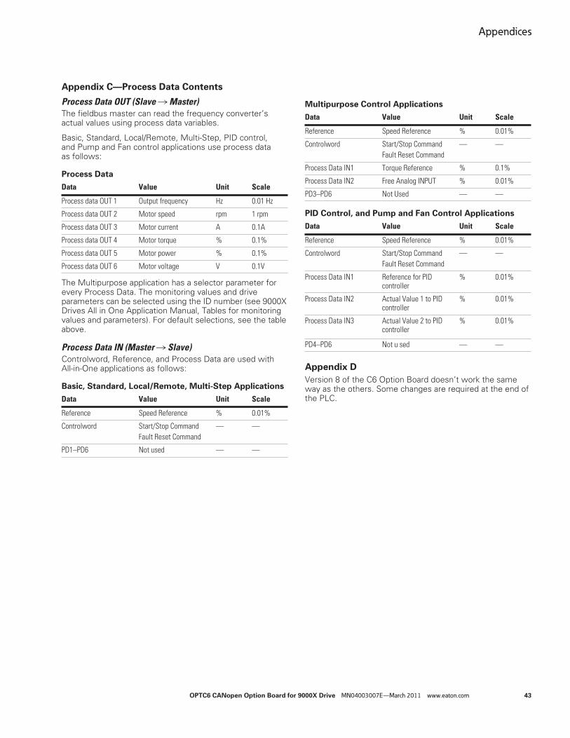
Appendices
OPTC6 CANopen Option Board for 9000X Drive MN04003007E—March 2011 www.eaton.com 43
Appendix C—Process Data Contents
Process Data OUT (Slave � Master)The fieldbus master can read the frequency converter’s actual values using process data variables.
Basic, Standard, Local/Remote, Multi-Step, PID control, and Pump and Fan control applications use process data as follows:
Process Data
The Multipurpose application has a selector parameter for every Process Data. The monitoring values and drive parameters can be selected using the ID number (see 9000X Drives All in One Application Manual, Tables for monitoring values and parameters). For default selections, see the table above.
Process Data IN (Master � Slave)Controlword, Reference, and Process Data are used with All-in-One applications as follows:
Basic, Standard, Local/Remote, Multi-Step Applications
Multipurpose Control Applications
PID Control, and Pump and Fan Control Applications
Appendix D
Version 8 of the C6 Option Board doesn’t work the same way as the others. Some changes are required at the end of the PLC.
Data Value Unit Scale
Process data OUT 1 Output frequency Hz 0.01 Hz
Process data OUT 2 Motor speed rpm 1 rpm
Process data OUT 3 Motor current A 0.1A
Process data OUT 4 Motor torque % 0.1%
Process data OUT 5 Motor power % 0.1%
Process data OUT 6 Motor voltage V 0.1V
Data Value Unit Scale
Reference Speed Reference % 0.01%
Controlword Start/Stop Command Fault Reset Command
— —
PD1–PD6 Not used — —
Data Value Unit Scale
Reference Speed Reference % 0.01%
Controlword Start/Stop Command Fault Reset Command
— —
Process Data IN1 Torque Reference % 0.1%
Process Data IN2 Free Analog INPUT % 0.01%
PD3–PD6 Not Used — —
Data Value Unit Scale
Reference Speed Reference % 0.01%
Controlword Start/Stop Command Fault Reset Command
— —
Process Data IN1 Reference for PID controller
% 0.01%
Process Data IN2 Actual Value 1 to PID controller
% 0.01%
Process Data IN3 Actual Value 2 to PID controller
% 0.01%
PD4–PD6 Not u sed — —


Eaton Corporation
Electrical Sector1111 Superior Ave.Cleveland, OH 44114United States877-ETN-CARE (877-386-2273)Eaton.com
©2011 Eaton CorporationAll Rights ReservedPrinted in USAPublication No. MN04003007E / Z10650March 2011
Eaton is a registered trademark of Eaton Corporation. All oher trademarks are property of their respective owners.
Eaton’s Electrical Sector isa global leader in power distribution, power quality, control and automation, and monitoring products. When combined with Eaton’s full-scale engineering services, these products provide customer-driven PowerChain™ solutionsto serve the power system needs of the data center, industrial, institutional, public sector, utility, commercial, residential, IT, mission critical, alternative energy and OEM markets worldwide.
PowerChain solutions help enterprises achieve sustainable and competitive advantages through proactive management of the power system as a strategic, integrated asset throughout its life cycle, resulting in enhanced safety, greater reliability and energy efficiency. For more information, visit www.eaton.com/electrical.