user manual the relay output module nano relay output poe
TRANSCRIPT

User manualThe Relay Output Module
Nano Relay Output PoE
Nano Relay Output
Soft >= 1.24
INVEO s.c.ul. Rzemieślnicza 21
43-340 Kozytel: +48 33 444 65 87
Dear Customer!
Thank you very much for choosing our product. Before its use, please read these instructions carefully. Here you find the most appropriate ways of dealing with this device, the basic principles of safety and maintenance. Please, also keep the user manual so that you can read it during later use.
Attention!
The manufacturer is not liable for any damage caused by improper use of the device which differ from its intended purpose, or improper handling, as well as a fault of driver resulting from improper use.
User manual Nano Relay Output PoE / Nano Relay Output Page 2 of 29[B04]

Contents:1 PRELIMINARY INFORMATION...................................................................................................................4
2 APPLICATION OF THE DEVICE..................................................................................................................5
3 WARRANTY AND LIABILITY OF THE MANUFACTURER...................................................................5
4 SAFETY GUIDELINES.....................................................................................................................................6
4.1 STORAGE, WORK AND TRANSPORT CONDITIONS.........................................................................................................64.2 INSTALLATION AND USE OF THE DEVICE..................................................................................................................64.3 DECOMMISSIONING OF THE DEVICE.........................................................................................................................6
5 CONSTRUCTION OF THE DEVICE..............................................................................................................7
5.1 NANO RELAY OUTPUT POE.................................................................................................................................75.2 NANO RELAY OUTPUT........................................................................................................................................9
6 CONFIGURATION OF THE DEVICE.........................................................................................................11
6.1 CHANGING THE DEVICE'S IP ADDRESS BY DISCOVERER APPLICATION.........................................................................116.2 CHANGING THE PC'S SUBNET ADDRESS, FOR THE DEVICE CONFIGURATION..................................................................126.3 SECURITY SETTINGS AND ADMINISTRATION............................................................................................................14
7 THE DEVICE FUNCTIONS...........................................................................................................................15
7.1 OUTPUT CONTROL.............................................................................................................................................157.2 CONFIGURATION OF THE OUTPUT CHANNEL............................................................................................................157.3 DESTINATION CLIENT (M2M)...........................................................................................................................177.4 SNMP CONFIGURATION....................................................................................................................................217.5 WINDOWS COMMAND LINE SOFTWARE..................................................................................................................227.6 LINUX CONTROL PROGRAM.................................................................................................................................227.7 MODBUS TCP.................................................................................................................................................237.8 MQTT...........................................................................................................................................................247.9 HTTP GET.....................................................................................................................................................257.10 TCP/UDP PROTOCOL.....................................................................................................................................27
8 COMMUNICATION WITH THE MODULE FROM THE EXTERNAL NETWORK...........................28
9 CHECKING THE IP ADDRESS.....................................................................................................................28
10 DHCP................................................................................................................................................................28
11 RESTORING FACTORY DEFAULTS........................................................................................................29
12 FIRMWARE UPDATE..................................................................................................................................29
User manual Nano Relay Output PoE / Nano Relay Output Page 3 of 29[B04]
1 Preliminary information
Before starting work with the device, read The User manual and follow the instructions contained therein!
Description of visual symbols used in this user manual:
This symbol is responsible for reviewing the appropriate place in the user instructions, warnings and important information. Failure to follow warnings could cause injury or damage to the device
Important information and guidelines
Following this guidelines makes the use of the device easier
Attention: The screenshots in this manual can be dissimilar from actual imagesat the time of the device purchase. Due to continuous development of the devices software, some of the functions may differ from these in the manual. The manufacturer claims no responsibility for any undesirable effects (misunderstanding) caused by changes of the software.
User manual Nano Relay Output PoE / Nano Relay Output Page 4 of 29[B04]
2 Application of the device
The Nano Relay Output device is used to control one electrical circuit using relay. The relay can be controlled using www website, network protocols (HTTP GET,Modbus TCP, SNMP, MQTT) TCP frame or software supplied by manufacturer.
3 Warranty and liability of the manufacturer
The manufacturer provides a 2-year warranty on the device. The manufacturer also provides post-warranty service for 10 years from the date of the introducing the device on the market. The warranty covers all defects in material and workmanship. The manufacturer undertakes to comply with the contract of guarantee, if the following conditions are met:
all repairs, alterations, extensions and device calibrations are performed by the manufacturer or authorized service,
supply network installation meets applicable standards in this regard, the device is operated in accordance with the recommendations outlined in this
manual, the device is used as intended.
The manufacturer assumes no responsibility for consequences resulting from improper installation, improper use of the device, not following this manual and the repairs of the device by individuals without permission.
This device doesn’t contain serviceable parts.
User manual Nano Relay Output PoE / Nano Relay Output Page 5 of 29[B04]
4 Safety guidelines
The device has been designed and built using modern electronic components, according to the latest trends in the global electronics. In particular, much emphasis was placed on ensuring optimum safety and reliability of control. The device has a housing with a high-quality plastic.
4.1 Storage, work and transport conditions
The device has to be stored in enclosed rooms which are free of caustic vapors and substances and also meet the requirements:
surrounding temperature from -30°C to +60°C, humidity from 25 to 90%, atmospheric pressure from 700 to 1060hPa.
The device working conditions: surrounding temperature from -10°C to +55°C, relative humidity from 30% to 75%, atmospheric pressure from 700 to 1060hPa.
Recommended transport conditions: surrounding temperature from -40°C to +85°C, relative humidity from 5% to 95%, atmospheric pressure from 700 to 1060hPa.
4.2 Installation and use of the deviceThe device should be used following the guidelines shown in next part of the user manual.
4.3 Decommissioning of the device When it becomes necessary to recycle the device (for instance, to decommission the device from service), please contact the manufacturer or its representative, who are obliged to respond, appropriately, i.e. collecting the device from the user. You can also ask the companies involved in recycling of electrical or computer equipment. Under no circumstances should you place the device along with other waste material.
User manual Nano Relay Output PoE / Nano Relay Output Page 6 of 29[B04]
5 Construction of the device
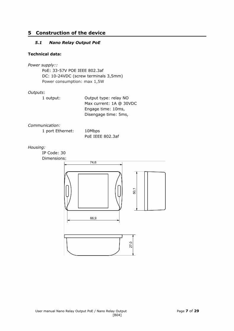
5.1 Nano Relay Output PoE
Technical data:
Power supply::PoE: 33-57V POE IEEE 802.3afDC: 10-24VDC (screw terminals 3,5mm)Power consumption: max 1,5W
Outputs: 1 output: Output type: relay NO
Max current: 1A @ 30VDCEngage time: 10ms,Disengage time: 5ms,
Communication:1 port Ethernet: 10Mbps
PoE IEEE 802.3af
Housing:IP Code: 30Dimensions:
User manual Nano Relay Output PoE / Nano Relay Output Page 7 of 29[B04]
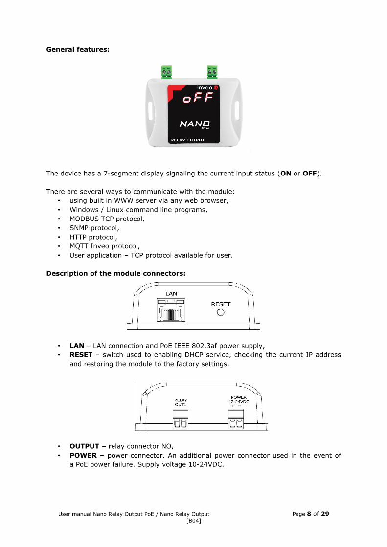
General features:
The device has a 7-segment display signaling the current input status (ON or OFF).
There are several ways to communicate with the module:• using built in WWW server via any web browser,• Windows / Linux command line programs,• MODBUS TCP protocol,• SNMP protocol,• HTTP protocol,• MQTT Inveo protocol,• User application – TCP protocol available for user.
Description of the module connectors:
• LAN – LAN connection and PoE IEEE 802.3af power supply,• RESET – switch used to enabling DHCP service, checking the current IP address
and restoring the module to the factory settings.
• OUTPUT – relay connector NO,• POWER – power connector. An additional power connector used in the event of
a PoE power failure. Supply voltage 10-24VDC.
User manual Nano Relay Output PoE / Nano Relay Output Page 8 of 29[B04]
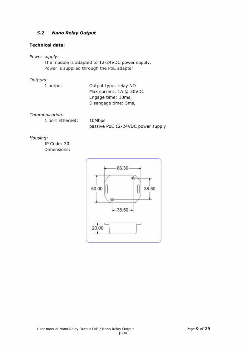
5.2 Nano Relay Output
Technical data:
Power supply:The module is adapted to 12-24VDC power supply.Power is supplied through the PoE adapter.
Outputs: 1 output: Output type: relay NO
Max current: 1A @ 30VDCEngage time: 10ms,Disengage time: 5ms,
Communication:1 port Ethernet: 10Mbps
passive PoE 12-24VDC power supply
Housing:IP Code: 30Dimensions:
User manual Nano Relay Output PoE / Nano Relay Output Page 9 of 29[B04]
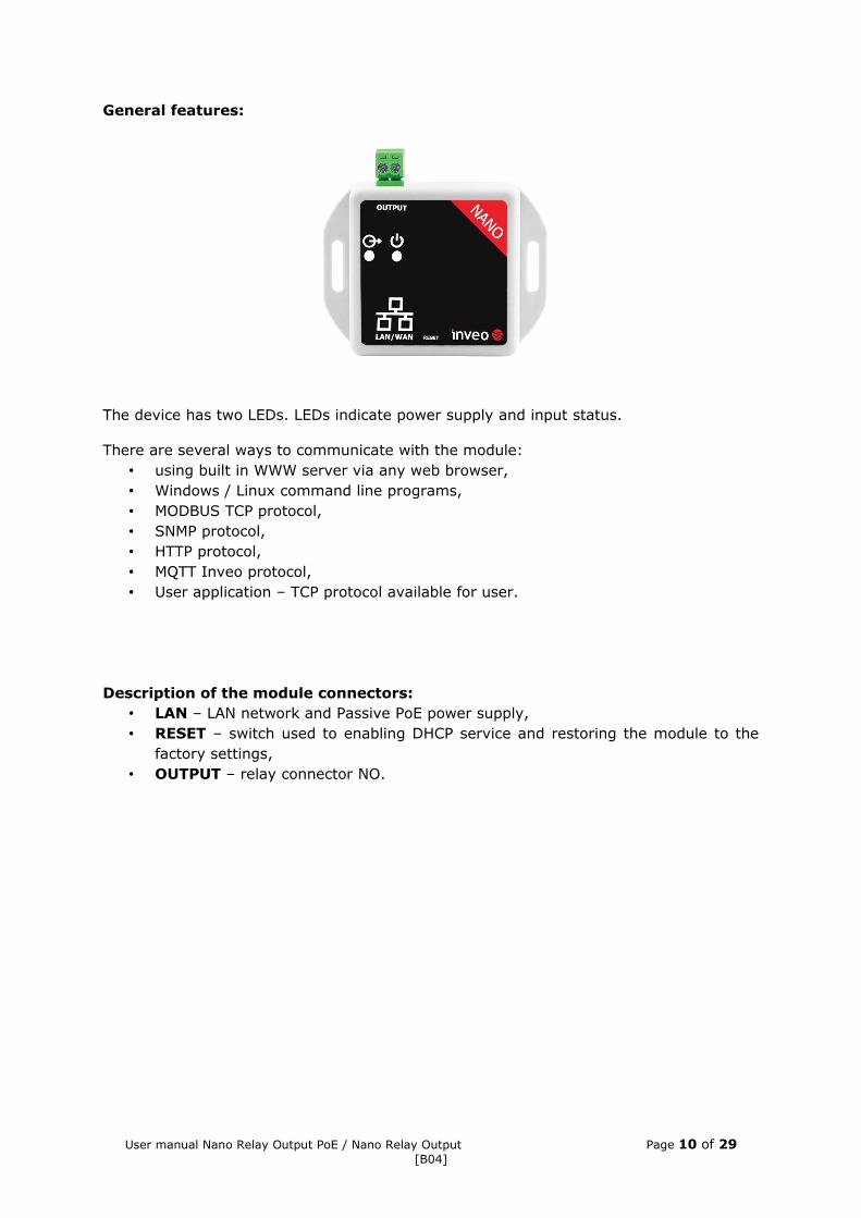
General features:
The device has two LEDs. LEDs indicate power supply and input status.
There are several ways to communicate with the module:• using built in WWW server via any web browser,• Windows / Linux command line programs,• MODBUS TCP protocol,• SNMP protocol,• HTTP protocol,• MQTT Inveo protocol,• User application – TCP protocol available for user.
Description of the module connectors:• LAN – LAN network and Passive PoE power supply,• RESET – switch used to enabling DHCP service and restoring the module to the
factory settings,• OUTPUT – relay connector NO.
User manual Nano Relay Output PoE / Nano Relay Output Page 10 of 29[B04]
6 Configuration of the device
The device when used for first time needs to be configured.There are two methods to do so. The network configuration can be easily changed by Inveo “Discoverer” (https://inveo.com.pl/software/) software:
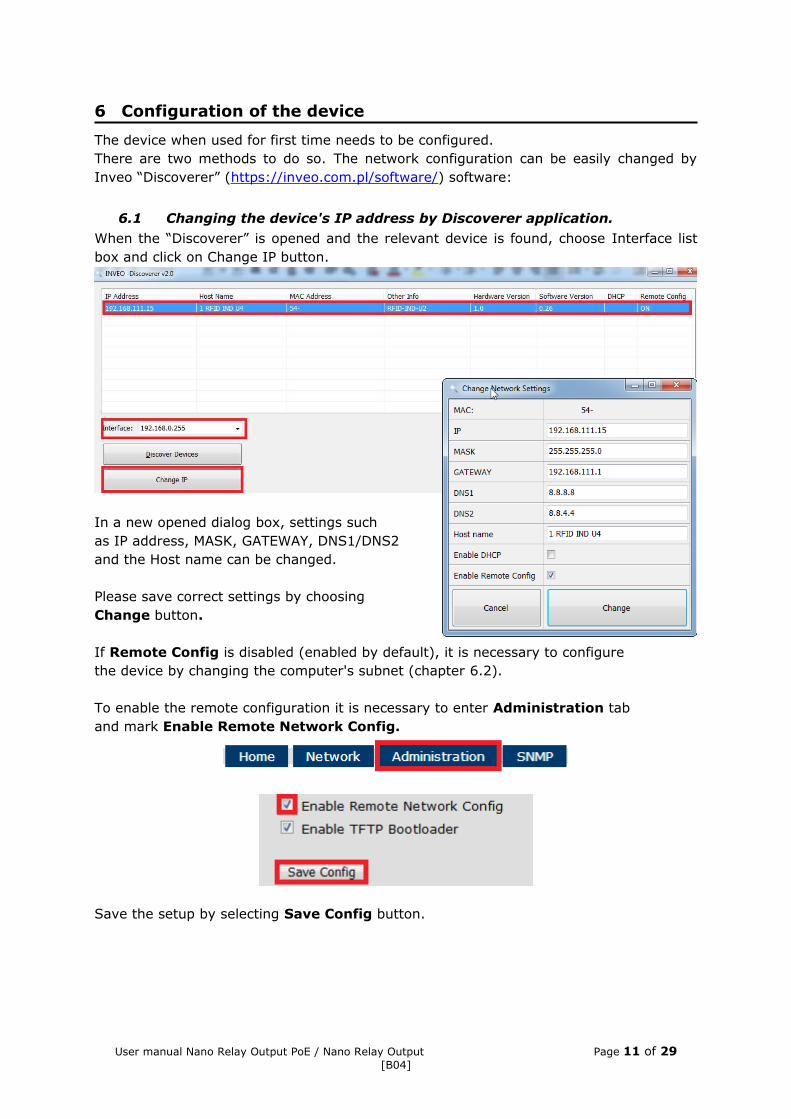
6.1 Changing the device's IP address by Discoverer application.When the “Discoverer” is opened and the relevant device is found, choose Interface list box and click on Change IP button.
In a new opened dialog box, settings suchas IP address, MASK, GATEWAY, DNS1/DNS2 and the Host name can be changed.
Please save correct settings by choosing Change button.
If Remote Config is disabled (enabled by default), it is necessary to configurethe device by changing the computer's subnet (chapter 6.2).
To enable the remote configuration it is necessary to enter Administration taband mark Enable Remote Network Config.
Save the setup by selecting Save Config button.
User manual Nano Relay Output PoE / Nano Relay Output Page 11 of 29[B04]
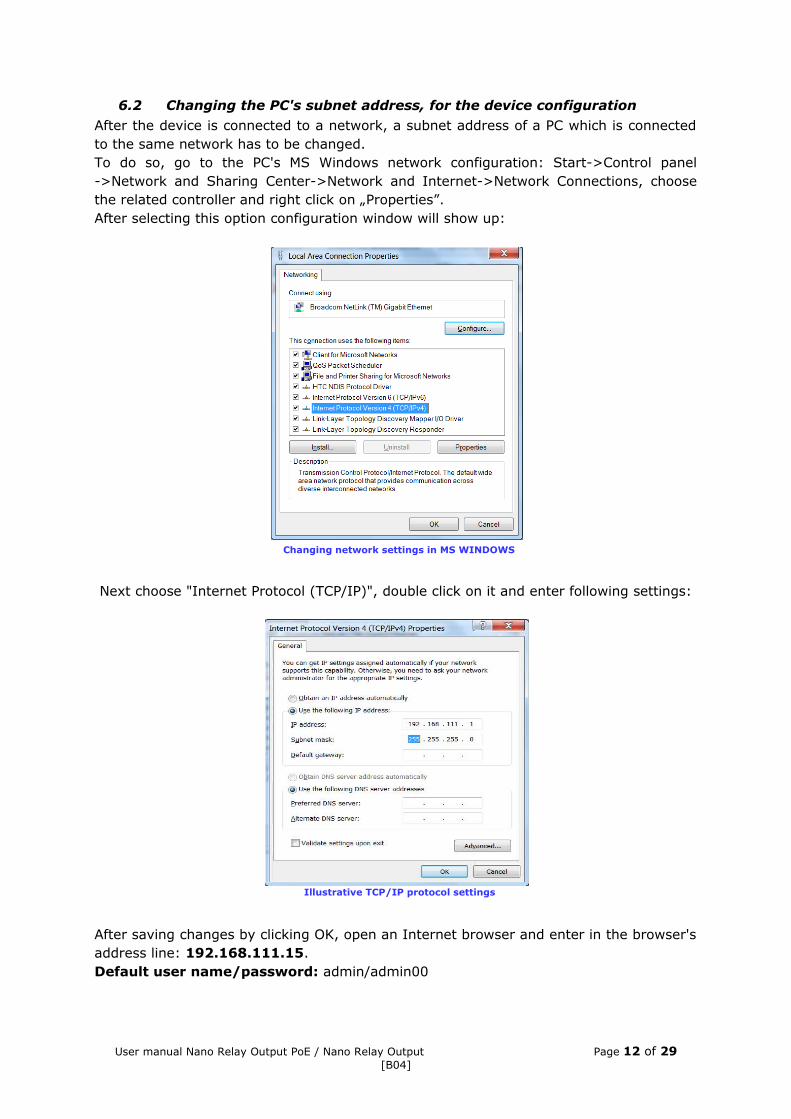
6.2 Changing the PC's subnet address, for the device configurationAfter the device is connected to a network, a subnet address of a PC which is connected to the same network has to be changed.To do so, go to the PC's MS Windows network configuration: Start->Control panel->Network and Sharing Center->Network and Internet->Network Connections, choose the related controller and right click on „Properties”.After selecting this option configuration window will show up:
Next choose "Internet Protocol (TCP/IP)", double click on it and enter following settings:
After saving changes by clicking OK, open an Internet browser and enter in the browser's address line: 192.168.111.15.Default user name/password: admin/admin00
User manual Nano Relay Output PoE / Nano Relay Output Page 12 of 29[B04]
Changing network settings in MS WINDOWS
Illustrative TCP/IP protocol settings
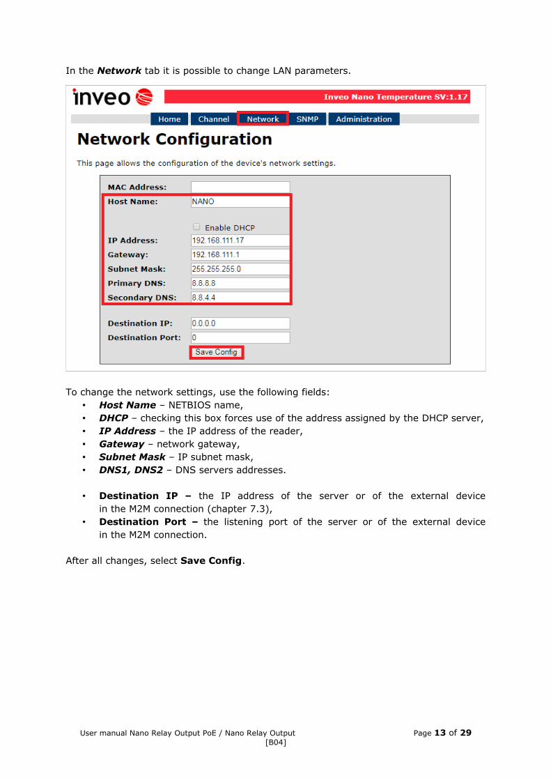
In the Network tab it is possible to change LAN parameters.
To change the network settings, use the following fields:• Host Name – NETBIOS name,• DHCP – checking this box forces use of the address assigned by the DHCP server,• IP Address – the IP address of the reader,• Gateway – network gateway,• Subnet Mask – IP subnet mask,• DNS1, DNS2 – DNS servers addresses.
• Destination IP – the IP address of the server or of the external devicein the M2M connection (chapter 7.3),
• Destination Port – the listening port of the server or of the external devicein the M2M connection.
After all changes, select Save Config.
User manual Nano Relay Output PoE / Nano Relay Output Page 13 of 29[B04]
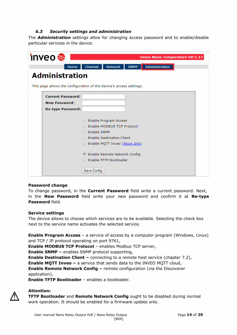
6.3 Security settings and administrationThe Administration settings allow for changing access password and to enable/disable particular services in the device.
Password changeTo change password, in the Current Password field write a current password. Next, in the New Password field write your new password and confirm it at Re-type Password field.
Service settingsThe device allows to choose which services are to be available. Selecting the check box next to the service name activates the selected service.
Enable Program Access – a service of access by a computer program (Windows, Linux) and TCP / IP protocol operating on port 9761,Enable MODBUS TCP Protocol – enables Modbus TCP server,Enable SNMP – enables SNMP protocol supporting,Enable Destination Client – connecting to a remote host service (chapter 7.2),Enable MQTT Inveo – a service that sends data to the INVEO MQTT cloud,Enable Remote Network Config – remote configuration (via the Discoverer application),Enable TFTP Bootloader – enables a bootloader.
Attention: TFTP Bootloader and Remote Network Config ought to be disabled during normal work operation. It should be enabled for a firmware update only.
User manual Nano Relay Output PoE / Nano Relay Output Page 14 of 29[B04]
7 The device functions
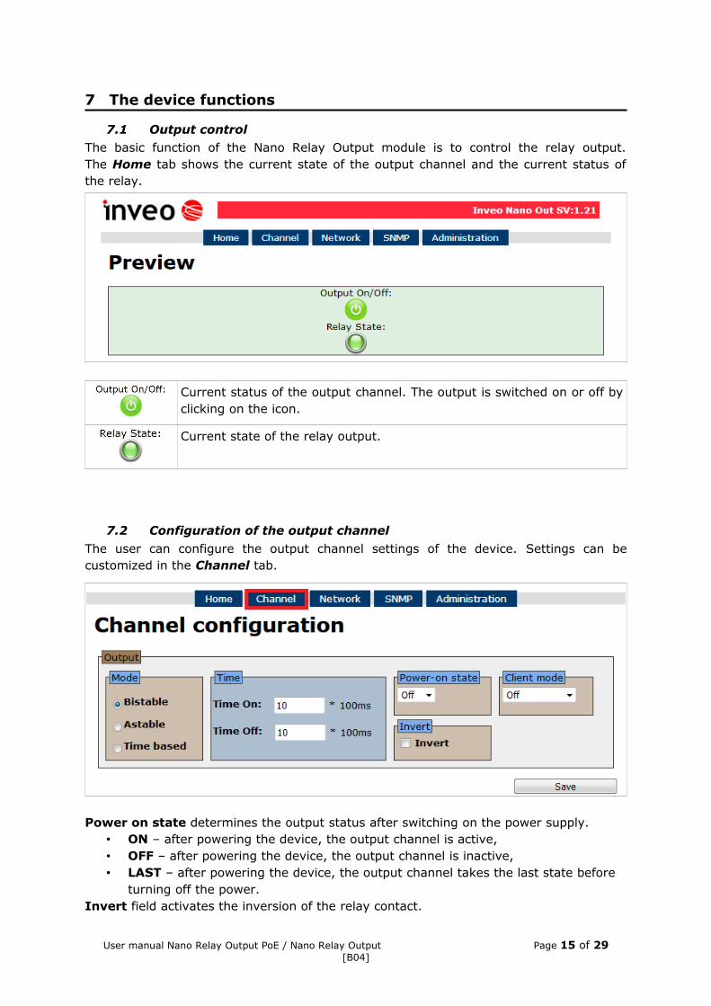
7.1 Output controlThe basic function of the Nano Relay Output module is to control the relay output.The Home tab shows the current state of the output channel and the current status of the relay.
Current status of the output channel. The output is switched on or off by clicking on the icon.
Current state of the relay output.
7.2 Configuration of the output channel
The user can configure the output channel settings of the device. Settings can be customized in the Channel tab.
Power on state determines the output status after switching on the power supply.• ON – after powering the device, the output channel is active,• OFF – after powering the device, the output channel is inactive,• LAST – after powering the device, the output channel takes the last state before
turning off the power.Invert field activates the inversion of the relay contact.
User manual Nano Relay Output PoE / Nano Relay Output Page 15 of 29[B04]

Output modeThe relay built into the device can work in 3 modes:
Bistable mode – a relay has one determined status (is engaged or disengaged), Astable mode – if the channel will be enabled, the relay is engage and disengage
cyclically. Time of engage and disengage relay:- Time On – time when a relay is engaged,- Time Off – time when a relay is disengaged.
TimeBased mode – one pulse mode.
o In TimeBased mode, if ton>0 and toff>0, after triggering the output,the relay will stay disengaged for toff and then it will engage for ton.
o In TimeBased mode, if ton >0 and toff=0, after triggering the output,the relay will engage for ton and after that it will disengage.
o In TimeBased mode, if ton=0 and toff>0, after triggering the output,the relay will stay disengaged for toff and then it will engage.
User manual Nano Relay Output PoE / Nano Relay Output Page 16 of 29[B04]
toff ton
ton
ton toff ton toff ton toff ton
toff
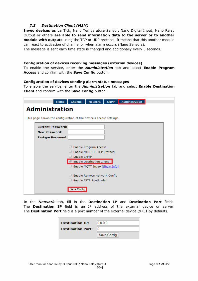
7.3 Destination Client (M2M)Inveo devices as LanTick, Nano Temperature Sensor, Nano Digital Input, Nano Relay Output or others are able to send information data to the server or to another module with outputs using the TCP or UDP protocol. It means that this another module can react to activation of channel or when alarm occurs (Nano Sensors). The message is sent each time state is changed and additionally every 5 seconds.
Configuration of devices receiving messages (external devices)To enable the service, enter the Administration tab and select Enable Program Access and confirm with the Save Config button.
Configuration of devices sending alarm status messagesTo enable the service, enter the Administration tab and select Enable Destination Client and confirm with the Save Config button.
In the Network tab, fill in the Destination IP and Destination Port fields.The Destination IP field is an IP address of the external device or server.The Destination Port field is a port number of the external device (9731 by default).
User manual Nano Relay Output PoE / Nano Relay Output Page 17 of 29[B04]
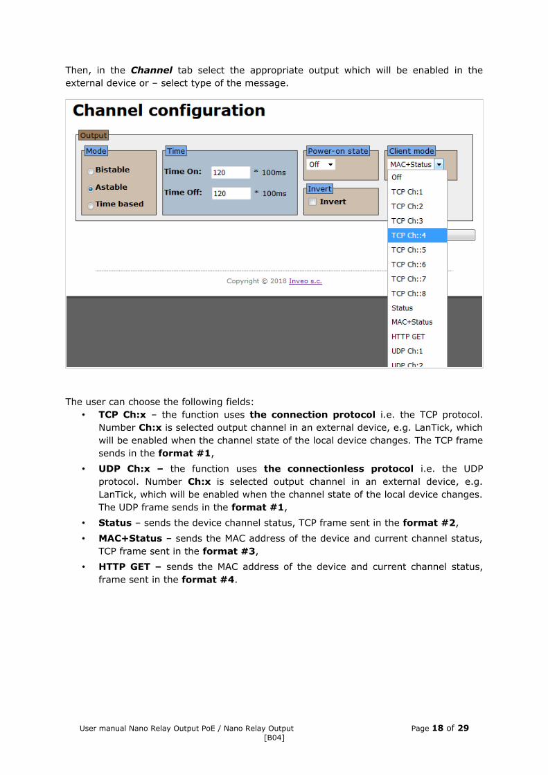
Then, in the Channel tab select the appropriate output which will be enabled in the external device or – select type of the message.
The user can choose the following fields:• TCP Ch:x – the function uses the connection protocol i.e. the TCP protocol.
Number Ch:x is selected output channel in an external device, e.g. LanTick, which will be enabled when the channel state of the local device changes. The TCP frame sends in the format #1,
• UDP Ch:x – the function uses the connectionless protocol i.e. the UDP protocol. Number Ch:x is selected output channel in an external device, e.g. LanTick, which will be enabled when the channel state of the local device changes. The UDP frame sends in the format #1,
• Status – sends the device channel status, TCP frame sent in the format #2,
• MAC+Status – sends the MAC address of the device and current channel status, TCP frame sent in the format #3,
• HTTP GET – sends the MAC address of the device and current channel status, frame sent in the format #4.
User manual Nano Relay Output PoE / Nano Relay Output Page 18 of 29[B04]
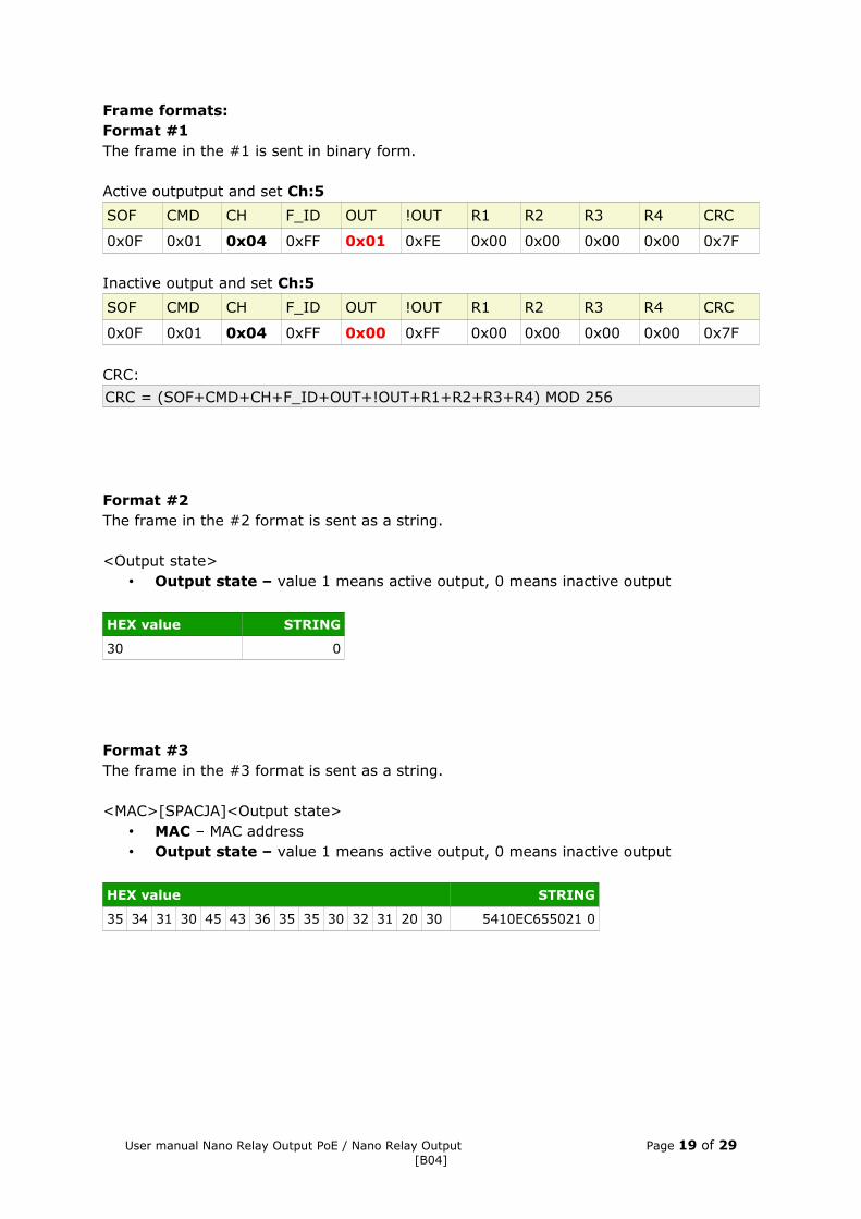
Frame formats:Format #1 The frame in the #1 is sent in binary form.
Active outputput and set Ch:5
SOF CMD CH F_ID OUT !OUT R1 R2 R3 R4 CRC
0x0F 0x01 0x04 0xFF 0x01 0xFE 0x00 0x00 0x00 0x00 0x7F
Inactive output and set Ch:5
SOF CMD CH F_ID OUT !OUT R1 R2 R3 R4 CRC
0x0F 0x01 0x04 0xFF 0x00 0xFF 0x00 0x00 0x00 0x00 0x7F
CRC:
CRC = (SOF+CMD+CH+F_ID+OUT+!OUT+R1+R2+R3+R4) MOD 256
Format #2The frame in the #2 format is sent as a string.
<Output state>• Output state – value 1 means active output, 0 means inactive output
HEX value STRING
30 0
Format #3The frame in the #3 format is sent as a string.
<MAC>[SPACJA]<Output state>• MAC – MAC address• Output state – value 1 means active output, 0 means inactive output
HEX value STRING
35 34 31 30 45 43 36 35 35 30 32 31 20 30 5410EC655021 0
User manual Nano Relay Output PoE / Nano Relay Output Page 19 of 29[B04]

Format #4Setting Client Mode to HTTP GET causes that the device sends data to the server in the form:
nano.php?mac=<MAC>&io=<Output state>• MAC – MAC address• Output state – value 1 means active output, 0 means inactive output
An example of a frame received by the server:GET /nano.php?mac=123456789012&io=1
address MAC = 123456789012,io=1, the output is enabled
The TCP frame can be handled with your own software.
An example of using the netcat command for Linux:Format #1
Format #2
Format #3
User manual Nano Relay Output PoE / Nano Relay Output Page 20 of 29[B04]
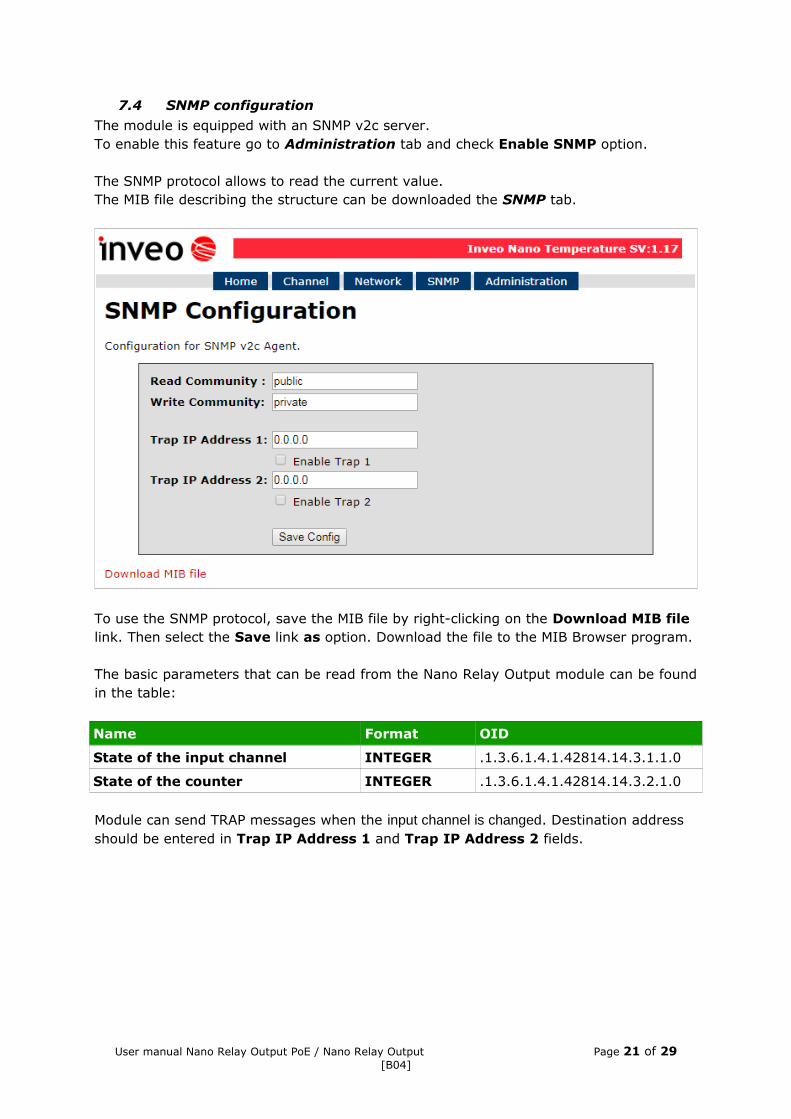
7.4 SNMP configurationThe module is equipped with an SNMP v2c server.To enable this feature go to Administration tab and check Enable SNMP option.
The SNMP protocol allows to read the current value.The MIB file describing the structure can be downloaded the SNMP tab.
To use the SNMP protocol, save the MIB file by right-clicking on the Download MIB file link. Then select the Save link as option. Download the file to the MIB Browser program.
The basic parameters that can be read from the Nano Relay Output module can be found in the table:
Name Format OID
State of the input channel INTEGER .1.3.6.1.4.1.42814.14.3.1.1.0
State of the counter INTEGER .1.3.6.1.4.1.42814.14.3.2.1.0
Module can send TRAP messages when the input channel is changed. Destination address should be entered in Trap IP Address 1 and Trap IP Address 2 fields.
User manual Nano Relay Output PoE / Nano Relay Output Page 21 of 29[B04]
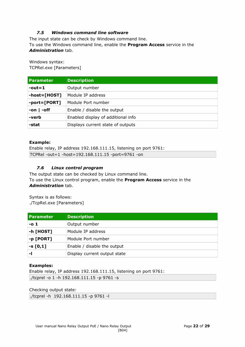
7.5 Windows command line softwareThe input state can be check by Windows command line.To use the Windows command line, enable the Program Access service in the Administration tab.
Windows syntax: TCPRel.exe [Parameters]
Parameter Description
-out=1 Output number
-host=[HOST] Module IP address
-port=[PORT] Module Port number
-on | -off Enable / disable the output
-verb Enabled display of additional info
-stat Displays current state of outputs
Example:Enable relay, IP address 192.168.111.15, listening on port 9761:
TCPRel -out=1 -host=192.168.111.15 -port=9761 -on
7.6 Linux control program
The output state can be checked by Linux command line.To use the Linux control program, enable the Program Access service in the Administration tab.
Syntax is as follows:./TcpRel.exe [Parameters]
Parameter Description
-o 1 Output number
-h [HOST] Module IP address
-p [PORT] Module Port number
-s [0,1] Enable / disable the output
-l Display current output state
Examples:Enable relay, IP address 192.168.111.15, listening on port 9761:
./tcprel -o 1 -h 192.168.111.15 -p 9761 -s
Checking output state:
./tcprel -h 192.168.111.15 -p 9761 -l
User manual Nano Relay Output PoE / Nano Relay Output Page 22 of 29[B04]
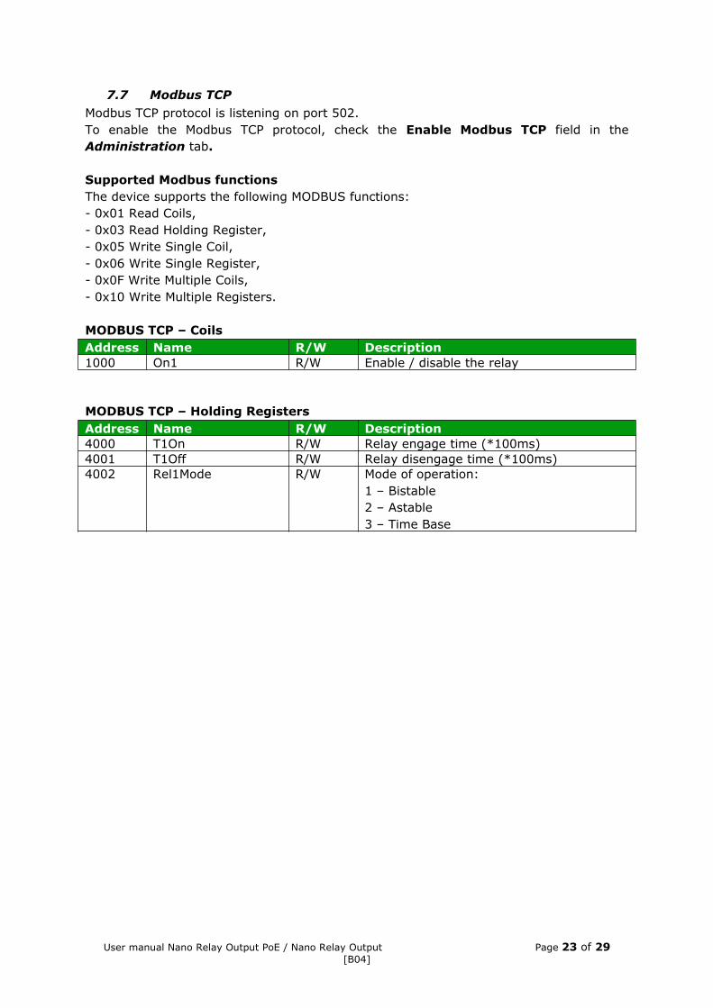
7.7 Modbus TCPModbus TCP protocol is listening on port 502.To enable the Modbus TCP protocol, check the Enable Modbus TCP field in the Administration tab.
Supported Modbus functionsThe device supports the following MODBUS functions:- 0x01 Read Coils,- 0x03 Read Holding Register,- 0x05 Write Single Coil,- 0x06 Write Single Register,- 0x0F Write Multiple Coils,- 0x10 Write Multiple Registers.
MODBUS TCP – CoilsAddress Name R/W Description1000 On1 R/W Enable / disable the relay
MODBUS TCP – Holding RegistersAddress Name R/W Description4000 T1On R/W Relay engage time (*100ms)4001 T1Off R/W Relay disengage time (*100ms)4002 Rel1Mode R/W Mode of operation:
1 – Bistable2 – Astable3 – Time Base
User manual Nano Relay Output PoE / Nano Relay Output Page 23 of 29[B04]

7.8 MQTT The device supports MQTT protocol. On the Network page, the user can configure his own MQTT broker address and port.
The MQTT service can be enabled in the Administration tab. The module sends data periodically every 1 minute and at each change.
The user can use Inveo’s MQTT broker. Application configuration for MQTT Client:• address: mqtt.inveo.com.pl,• port: 1883,• username: nanouser,• user password: nanouser,• topic: /nanoO/<MAC>.
Username and password are the same for Inveo’s server and the user custom server.
In the Administration tab after click [Show Info] the MQTT client settings will be displayed.
There are many applications on Android, IOS or PC that can display data sent by the module using MQTT.
The user can control output via MQTT – just check Enable MQTT output control in the Administration tab.Publish topic syntax: /nosec/nanoO/s/MAC with value:
• 1 – switch on the relay output (mode as defined in the Channel tab),• 0 – switch off the relay output.
User manual Nano Relay Output PoE / Nano Relay Output Page 24 of 29[B04]

7.9 HTTP GetNano modules can be controlled using HTTP GET.To read the current state of the module, you can refer to the resource in the web browser: http://192.168.111.15/status.xml
XML file consist all of the information:<response>
<prod_name>Nano-1-0</prod_name><sv>1.21</sv><mac>00:00:00:00:00:00</mac><out>00000001</out><on>00000001</on><in>00000000</in><counter1>0</counter1><temp1>0.0</temp1>
</response>
Section Description<prod_name>Nano-1-0</prod_name> Module type<sv>1.17</sv> The software version of the module<mac>00:00:00:00:00:00</mac> MAC address of the module<out>00000001</out> Relay state<on>00000001</on> Output state<in>00000000</in> In the Nano Relay Output module always 0<counter1>0</counter1> In the Nano Relay Output module always 0<temp1>0.0</temp1> In the Nano Relay Output module always 0
HTTP GET command Descriptionhttp://nr_ip/stat.php?on=1 Enable output relayhttp://nr_ip/stat.php?off=1 Disable output relayhttp://nr_ip/stat.php?inv=1 Invert output statehttp://nr_ip/stat.php?set=0000000x Set output
Available options x=:1 – enable0 – disablen – invert- - no changes
Examples of module control using the HTTP GET protocol:1. Enable relay output: http://192.168.111.15/stat.php?o n =1
2. Invert output relay state:http://192.168.111.15/stat.php? inv=1
3. Disable relay output: http://192.168.111.15/stat.php?off=1
User manual Nano Relay Output PoE / Nano Relay Output Page 25 of 29[B04]
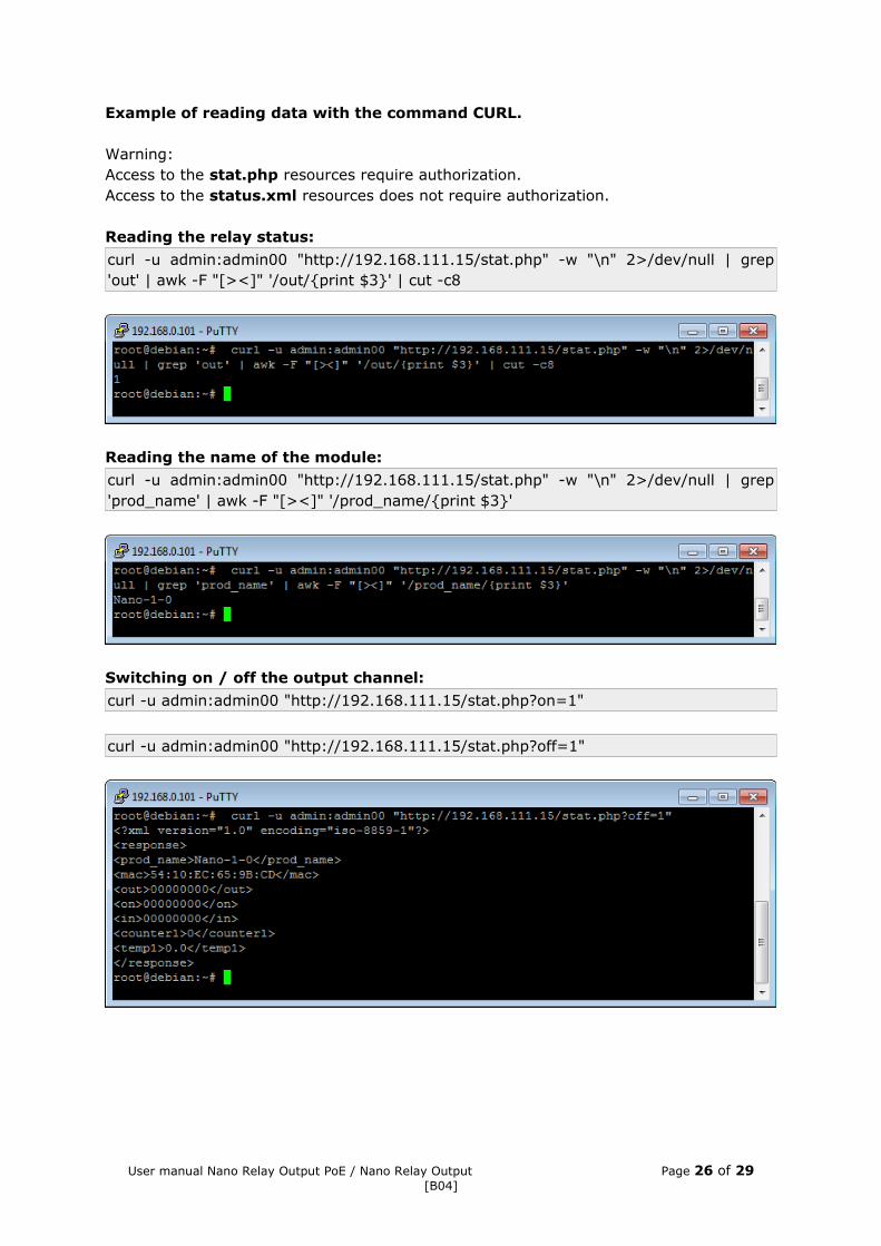
Example of reading data with the command CURL.
Warning:Access to the stat.php resources require authorization.Access to the status.xml resources does not require authorization.
Reading the relay status:
curl -u admin:admin00 "http://192.168.111.15/stat.php" -w "\n" 2>/dev/null | grep 'out' | awk -F "[><]" '/out/{print $3}' | cut -c8
Reading the name of the module:
curl -u admin:admin00 "http://192.168.111.15/stat.php" -w "\n" 2>/dev/null | grep 'prod_name' | awk -F "[><]" '/prod_name/{print $3}'
Switching on / off the output channel:
curl -u admin:admin00 "http://192.168.111.15/stat.php?on=1"
curl -u admin:admin00 "http://192.168.111.15/stat.php?off=1"
User manual Nano Relay Output PoE / Nano Relay Output Page 26 of 29[B04]

7.10 TCP/UDP protocolFrame for the TCP / UDP port 9761.
Command
Nr bajtu
1 2 3 4 5 6 7 8 9 10 11
Nazwa bajtu
SOF CMD Channel Data1 Data2 Data3 Data4 Data5 Data6 Data7 CRC Return
Output control
dec 15 1 0-7Mode [1-3]*
On/Off[0,1]
TONLSB
TONMSB
TOFFLSB
TOFFMSB
Power on state
[0-2]CRC OK
hex 0x0F 0x01 0x00Mode [1-3]*
0-1TONLSB
TONMSB
TOFFLSB
TOFFMSB
[0-2] CRC OK
Downloading channel
parameters
dec 15 2 0-7 x x x x x x x CRC
hex 0x0F 0x02 0-7 x x x x x x x CRC
Writing to the EPROM memory
dec 15 20 0 10 0 0 0 0 0 11 CRC OK
hex 0x0F 0x14 0x00 0x0A 0x00 0x00 0x00 0x00 0x00 0x0B 0x38 OK
Read channels
state
dec 15 100 x x x x x x x x 115CH7-
CH0**
hex 0x0F 0x64 x x x x x x x x 0x73CH7-
CH0**
Read device name
dec 15 200 x x x x x x x x 215 String
hex 0x0F 0xC8 x x x x x x x x 0xD7 String
** Chx returns 2 bytes:• 1 – output state,• 2 – coil state.
Description Value State
On/Off 0 Off
1 On
*Mode 1 Bistable
2 Astable
3 Time based
CRC The sum of bytes
Set the output to astable mode with time Ton = Toff = 1.7 seconds.
SOF CMD CH D1 D2 D3 D4 D5 D6 D7 CRC
dec 15 1 0 2 1 17 0 17 0 0 53
hex 0x0F 0x01 0x00 0x02 0x01 0x11 0x00 0x11 0x00 0x00 0x35
Save settings to the EPROM memory.
dec 15 1 0 2 1 17 0 17 0 0 53
hex 0x0F 0x01 0x00 0x02 0x01 0x11 0x00 0x11 0x00 0x00 0x35
User manual Nano Relay Output PoE / Nano Relay Output Page 27 of 29[B04]

8 Communication with the module from the external network
If the module is in a different LAN network than the computer connecting to it, port forwarding is required.Depending on the communication method used with the module, it is necessary to contact the Network Administrator and port forwarding:
Support via website and HTTP protocol:- port TCP 80
Service by a computer program or by your own application:- port TCP 9761
Support via MODBUS TCP:- port TCP 502
Support via SNMP protocol:- port UDP 161
9 Checking the IP address
To check the current IP address of the device (Nano Relay Output PoE only):1. Press and hold the reset button until the display shows the four parts of the IP
number, e.g. 192 168 111 15.2. Release the reset button.
10 DHCP
To enable/disable DHCP service:1. Press and hold RESET button 5 to 10 second.2. Green LED will start flashing 2 times a second (Nano Relay Output), the display
will show: dhcP (Nano Relay Output PoE).3. Release the reset button.
It is also possible to enable DHCP in the network configuration in the Network tab or through Discoverer application.
User manual Nano Relay Output PoE / Nano Relay Output Page 28 of 29[B04]
11 Restoring factory defaults
To reset the device to factory settings:1. Press and hold RESET button for 10 to 15 seconds 2. Green LED will start flashing 2 times a second (Nano Relay Output), the display
will show: rSt (Nano Relay Output PoE).3. Release the reset button.
With factory defaults restored the module settings are as follows:• DHCP: enabled• IP address: 192.168.111.15• IP mask: 255.255.255.0• User name: admin• Password: admin00
12 Firmware update
The device has the ability to update the firmware. The software update program is provided as a *.bin file.
Warning! Incorrect use of the update feature may damage the reader. Make sure that undisturbed power is provided to the device for duration of programming.
To update the software:• check the Enable TFTP Bootloader option, which is located in the Administration
tab,• run the Windows command line (Start-> Run enter 'cmd' and confirm with the
Enter key),• go to the directory where the .bin file is located• enter the command:
tftp -i <address_ip_of the reader> PUT file.bin
where: <address_ip_of the reader> is the IP Address of the readerfile.bin – the file with the update program
Programming takes 1-2 minutes. End of programming confirms the message 'FileTransferred'.
For correct functioning of the reader, after the update operation the „Enable TFTP Bootloader” option has to be switched off.
Step-by-step instruction for firmware updates is available at https://inveo.com.pl.
The latest instructions and software are available on the site https://inveo.com.p l .
User manual Nano Relay Output PoE / Nano Relay Output Page 29 of 29[B04]