user manual - tkn deutschland thomson thg571 … · user manual satellite telecom cable terrestrial...
TRANSCRIPT

User manual
SATELLITE TELECOMCABLE
TERRESTRIAL
THG571 - Voice Over IP Cable Modem
Important Information
ii
This symbol means that your inoperative electronic appliance must be collected separately
and not mixed with the household waste. The European Union has implemented a specific
collection and recycling system for which producers' are responsible.
This appliance has been designed and manufactured with high quality
materials and components that can be recycled and reused. Electrical and electronic
appliances are liable to contain parts that are necessary in order for the system to work
properly but which can become a health and environmental hazard if they are not handled or
disposed of in the proper way. Consequently, please do not throw out your inoperative
appliance with the household waste.
If you are the owner of the appliance, you must deposit it at the appropriate local collection
point or leave it with the vendor when buying a new appliance.
- If you are a professional user, please follow your supplier's instructions.
- If the appliance is rented to you or left in your care, please contact your service
provider.
Help us protect the environment in which we live!

Important Information
iii
North American Cable Installer This reminder is provided to call your attention to Article 820-40 of the
National Electrical Code (Section 54 of the Canadian Electrical Code, Part 1) which provides guidelines for
proper grounding and, in particular, specifies that the cable ground shall be connected to the grounding system
of the building as close to the point of cable entry as practical.
Power Supply Information The power supply can be unplugged to turn off main power to the cable modem. It should also be easily
accessible in an emergency.
Power Cord Requirement This product must be operated with the supplied line cord or with a line cord meeting IEC227 H03 VV-F or
IEC227 H03 VVH2-F having conductors with a cross-sectional area not less than .75mm2.
Operating Information
Operating Temperature: 0˚ to 40˚ C (32˚ to 104˚ F)
Storage Temperature: -20˚ to 70˚ C (-4˚ to 158˚ F)
If you purchased this product at a retail outlet, please read the following:
Product Registration
Please fill out the product registration card that came with this product and return it immediately.
Returning the card allows us to contact you if needed.
Keep your sales receipt to obtain warranty parts and service and for proof of purchase. Attach it here and
record the serial and model numbers in case you need them. The numbers are located on the back of the
product.
Model No. ____________________________ Serial No _____________________________
Purchase Date: _________________________ Dealer/Address/Phone: __________________
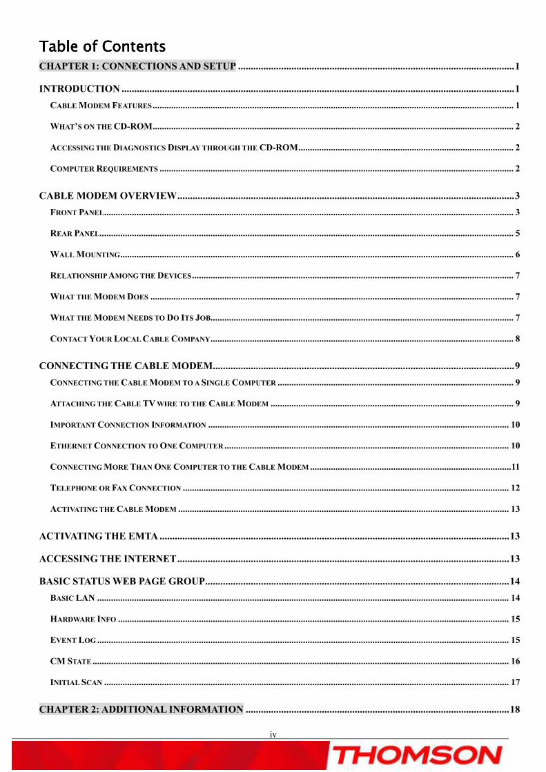
Table of ContentsTable of ContentsTable of ContentsTable of Contents
iv
CHAPTER 1: CONNECTIONS AND SETUP ............................................................................................................. 1
INTRODUCTION ........................................................................................................................................................... 1
CABLE MODEM FEATURES ............................................................................................................................................................ 1
WHAT’S ON THE CD-ROM ............................................................................................................................................................ 2
ACCESSING THE DIAGNOSTICS DISPLAY THROUGH THE CD-ROM ............................................................................................. 2
COMPUTER REQUIREMENTS ......................................................................................................................................................... 2
CABLE MODEM OVERVIEW ..................................................................................................................................... 3
FRONT PANEL ................................................................................................................................................................................. 3
REAR PANEL................................................................................................................................................................................... 5
WALL MOUNTING .......................................................................................................................................................................... 6
RELATIONSHIP AMONG THE DEVICES ........................................................................................................................................... 7
WHAT THE MODEM DOES ............................................................................................................................................................. 7
WHAT THE MODEM NEEDS TO DO ITS JOB................................................................................................................................... 7
CONTACT YOUR LOCAL CABLE COMPANY ................................................................................................................................... 8
CONNECTING THE CABLE MODEM ....................................................................................................................... 9
CONNECTING THE CABLE MODEM TO A SINGLE COMPUTER ...................................................................................................... 9
ATTACHING THE CABLE TV WIRE TO THE CABLE MODEM ......................................................................................................... 9
IMPORTANT CONNECTION INFORMATION .................................................................................................................................. 10
ETHERNET CONNECTION TO ONE COMPUTER ........................................................................................................................... 10
CONNECTING MORE THAN ONE COMPUTER TO THE CABLE MODEM ....................................................................................... 11
TELEPHONE OR FAX CONNECTION ............................................................................................................................................. 12
ACTIVATING THE CABLE MODEM ............................................................................................................................................... 13
ACTIVATING THE EMTA .......................................................................................................................................... 13
ACCESSING THE INTERNET ................................................................................................................................... 13
BASIC STATUS WEB PAGE GROUP ........................................................................................................................ 14
BASIC LAN .................................................................................................................................................................................. 14
HARDWARE INFO ......................................................................................................................................................................... 15
EVENT LOG .................................................................................................................................................................................. 15
CM STATE .................................................................................................................................................................................... 16
INITIAL SCAN ............................................................................................................................................................................... 17
CHAPTER 2: ADDITIONAL INFORMATION ........................................................................................................ 18

Table of ContentsTable of ContentsTable of ContentsTable of Contents
v
FREQUENTLY ASKED QUESTIONS ....................................................................................................................... 18
GENERAL TROUBLESHOOTING ........................................................................................................................... 19
FCC DECLARATION OF CONFORMITY AND INDUSTRY CANADA INFORMATION ................................ 20
SERVICE INFORMATION ......................................................................................................................................... 20
GLOSSARY ................................................................................................................................................................... 21

Chapter 1: Connection and SetupChapter 1: Connection and SetupChapter 1: Connection and SetupChapter 1: Connection and Setup
1
ChapterChapterChapterChapter 1: Connections and Setup1: Connections and Setup1: Connections and Setup1: Connections and Setup
IntroductionIntroductionIntroductionIntroduction
Cable Modem Features
� CableLabs DOCSIS 1.0/1.1/2.0/3.0 Standard Compliant. / Cable Europe Lab EuroDOCSIS
1.0/1.1/2.0/3.0 Standard Certified.
� Support Multiple Provisioning Modes.
� Support PacketCable / EuroPacketCable NCS 1.0/1.5/2.0 (optional) MGCP 1.0 compliant (Media
Gateway Control Protocol) (optional configuration: SIP).
� Standard RJ-45 connector for 10/100/1000BaseT Ethernet with auto-negotiation and MDIX functions;
Support maximum Ethernet cable length up to 100m (Category 5).
� Support up to 8 downstream channels and up to 4 upstream channels.
� Giga tuner design.
� Maximum data rate upstream up to 131Mbps (Theoretical) and downstream up to 440 Mbps
(Theoretical).
� Two RJ-11 Foreign Exchange Station (FXS) ports for IP telephony; Support a maximum line length
between themselves and an end-receiver (handset, answering phone, etc.) of up to 500 feet (AWG
26/0.4mm).
� Support simultaneous voice and data communications.
� Two simultaneous voice conversations in the different FXS ports with different CODEC: PCM A-law,
PCM µ-law, G.723.1, G.729, G.729a, G.729e, G.728, G.726, iLBC and BV16.
� Echo Cancellation.
� Voice Active Detection (VAD).
� DTMF detection and generation.
� Comfort Noise Generation (CNG).
� Support V.90 fax and modem services.
� Transparent bridging for IP traffic.
� Remote operating firmware downloading.
� Support Web pages and private DHCP server for status monitoring.
� Clear LED display
� Support 5 REN when DC offset disable
� Both connections are not linked together (TEL1 is not connected to TEL2). Connection in general used
in Europe: Pin 3 and 4 are used on port Tel1, Pin3 and 4 are used on port Tel2.
� Individual FXS ports, Tel1 and Tel2 phone jacks are not cross wired.
� TEL 1 and TEL 2 port are not connected on Hardware side.
The following may affect the speed of your cable modem: your computer equipment and configuration
(processor speed, amount of RAM, available disk space); the number of programs you are running at the
same time; the capacity of your ISP; network traffic levels; the Ethernet device in use on your computer.
Your cable company may or may not fully support the speed capabilities of this modem.
Chapter 1: Connection and SetupChapter 1: Connection and SetupChapter 1: Connection and SetupChapter 1: Connection and Setup
2
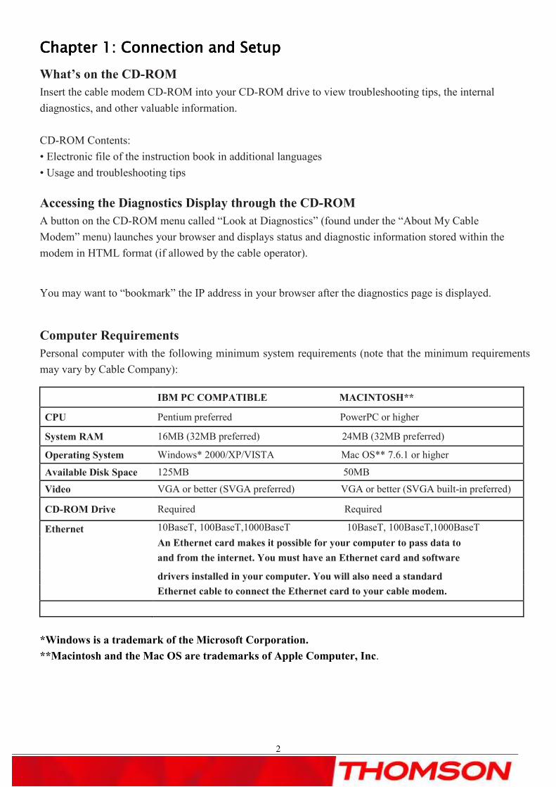
What’s on the CD-ROM
Insert the cable modem CD-ROM into your CD-ROM drive to view troubleshooting tips, the internal
diagnostics, and other valuable information.
CD-ROM Contents:
• Electronic file of the instruction book in additional languages
• Usage and troubleshooting tips
Accessing the Diagnostics Display through the CD-ROM
A button on the CD-ROM menu called “Look at Diagnostics” (found under the “About My Cable
Modem” menu) launches your browser and displays status and diagnostic information stored within the
modem in HTML format (if allowed by the cable operator).
You may want to “bookmark” the IP address in your browser after the diagnostics page is displayed.
Computer Requirements
Personal computer with the following minimum system requirements (note that the minimum requirements
may vary by Cable Company):
IBM PC COMPATIBLE MACINTOSH**
CPU Pentium preferred PowerPC or higher
System RAM 16MB (32MB preferred) 24MB (32MB preferred)
Operating System Windows* 2000/XP/VISTA Mac OS** 7.6.1 or higher
Available Disk Space 125MB 50MB
Video VGA or better (SVGA preferred) VGA or better (SVGA built-in preferred)
CD-ROM Drive Required Required
Ethernet 10BaseT, 100BaseT,1000BaseT 10BaseT, 100BaseT,1000BaseT
An Ethernet card makes it possible for your computer to pass data to
and from the internet. You must have an Ethernet card and software
drivers installed in your computer. You will also need a standard
Ethernet cable to connect the Ethernet card to your cable modem.
*Windows is a trademark of the Microsoft Corporation.
**Macintosh and the Mac OS are trademarks of Apple Computer, Inc.
Chapter 1: Connections and Setup
3
Cable Modem Overview
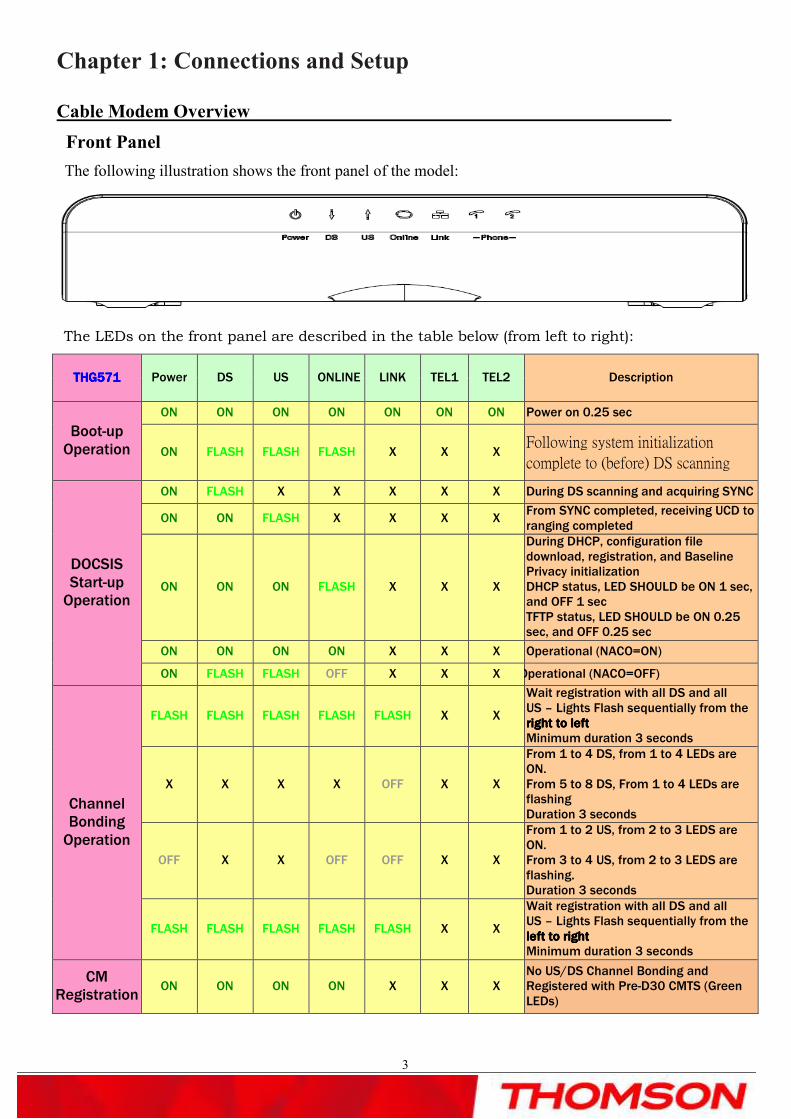
Front Panel
The following illustration shows the front panel of the model:
The LEDs on the front panel are described in the table below (from left to right):
THG57THG57THG57THG571111 Power DS US ONLINE LINK TEL1 TEL2 Description
Boot-up Operation
ON ON ON ON ON ON ON Power on 0.25 sec
ON FLASH FLASH FLASH X X X Following system initialization
complete to (before) DS scanning
DOCSIS Start-up Operation
ON FLASH X X X X X During DS scanning and acquiring SYNC
ON ON FLASH X X X X From SYNC completed, receiving UCD to ranging completed
ON ON ON FLASH X X X
During DHCP, configuration file download, registration, and Baseline Privacy initialization DHCP status, LED SHOULD be ON 1 sec, and OFF 1 sec TFTP status, LED SHOULD be ON 0.25 sec, and OFF 0.25 sec
ON ON ON ON X X X Operational (NACO=ON)
ON FLASH FLASH OFF X X X Operational (NACO=OFF)
Channel Bonding Operation
FLASH FLASH FLASH FLASH FLASH X X
Wait registration with all DS and all US – Lights Flash sequentially from the right to leftright to leftright to leftright to left Minimum duration 3 seconds
X X X X OFF X X
From 1 to 4 DS, from 1 to 4 LEDs are ON. From 5 to 8 DS, From 1 to 4 LEDs are flashing Duration 3 seconds
OFF X X OFF OFF X X
From 1 to 2 US, from 2 to 3 LEDS are ON. From 3 to 4 US, from 2 to 3 LEDS are flashing. Duration 3 seconds
FLASH FLASH FLASH FLASH FLASH X X
Wait registration with all DS and all US – Lights Flash sequentially from the left to rightleft to rightleft to rightleft to right Minimum duration 3 seconds
CM Registration
ON ON ON ON X X X No US/DS Channel Bonding and Registered with Pre-D30 CMTS (Green LEDs)
Chapter 1: Connections and Setup
4
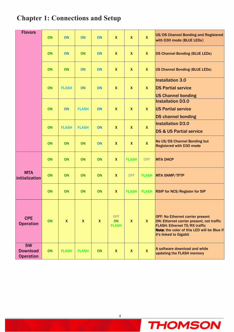
Flavors ON ON ON ON X X X
US/DS Channel Bonding and Registered
with D30 mode (BLUE LEDs)
ON ON ON ON X X X DS Channel Bonding (BLUE LEDs)
ON ON ON ON X X X US Channel Bonding (BLUE LEDs)
ON FLASH ON ON X X X
Installation 3.0
DS Partial service
US Channel bonding
ON ON FLASH ON X X X
Installation D3.0
US Partial service
DS channel bonding
ON FLASH FLASH ON X X X Installation D3.0
DS & US Partial service
ON ON ON ON X X X No US/DS Channel Bonding but Registered with D30 mode
MTA initialization
ON ON ON ON X FLASH OFF MTA DHCP
ON ON ON ON X OFF FLASH MTA SNMP/TFTP
ON ON ON ON X FLASH FLASH RSIP for NCS/Register for SIP
CPE Operation
ON X X X OFF ON
FLASH X X
OFF: No Ethernet carrier present ON: Ethernet carrier present, not traffic FLASH: Ethernet TX/RX traffic Note:Note:Note:Note: the color of this LED will be Blue if it's linked to Gigabit
SW Download Operation
ON FLASH FLASH ON X X X A software download and while updating the FLASH memory

Chapter 1: Connections and Setup
5
Rear Panel
� TEL 1 and TEL 2: RJ-11 Phone set connector
� GIGA ETHERNET: Ethernet 10/100/1000BaseT RJ-45 connector
� Reset: Reboot CM
� CABLE: F-Connector
� 12VDC: AC power socket
� On/off switch: Switch to power on/off this cable modem
Chapter 1: Connections and Setup
6
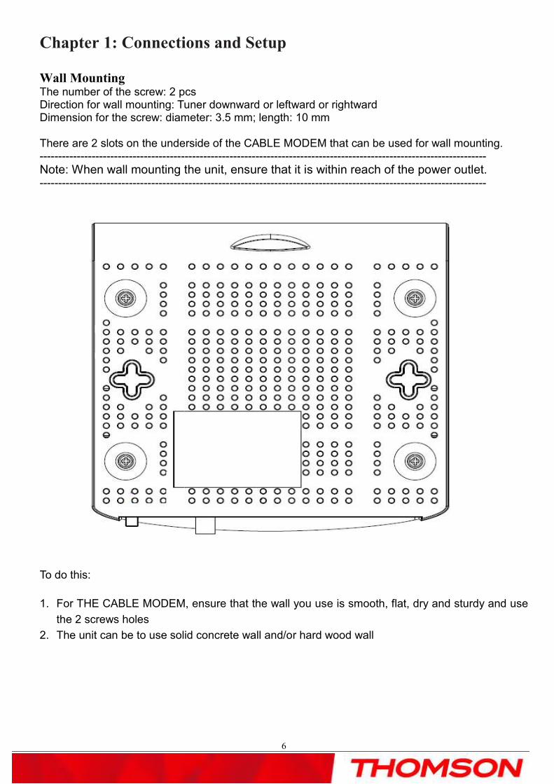
Wall Mounting The number of the screw: 2 pcs Direction for wall mounting: Tuner downward or leftward or rightward Dimension for the screw: diameter: 3.5 mm; length: 10 mm There are 2 slots on the underside of the CABLE MODEM that can be used for wall mounting. ------------------------------------------------------------------------------------------------------------------------
Note: When wall mounting the unit, ensure that it is within reach of the power outlet. ------------------------------------------------------------------------------------------------------------------------
To do this:
1. For THE CABLE MODEM, ensure that the wall you use is smooth, flat, dry and sturdy and use
the 2 screws holes
2. The unit can be to use solid concrete wall and/or hard wood wall

Chapter 1: Connections and Setup
7
Relationship Among the Devices
This illustration shows a cable company that offers DOCSIS/Euro-DOCSIS compliant Internet services
Computer Cable Modem Cable Company Internet
What the Modem Does
The Thomson digital cable modem serves as a two-way high-speed bridge between your personal computer
and a cable Internet Service Provider (ISP). It converts information that originates from the Internet or your
computer into electronic messages that can be transported over the same wires your cable
company uses to transport video signals.
What the Modem Needs to Do Its Job
• The Right Cable Company: Make sure your local cable company provides data
services that use cable industry-standard DOCSIS/Euro-DOCSIS technology
compatible with your cable modem.
• The Internet Service Provider (ISP): Your cable company provides you access to an Internet
Service Provider (ISP). The ISP is your gateway to the Internet. It provides you with a pipeline to
access Internet content on the World Wide Web (WWW).
Check with your cable company to make sure you have everything you need to begin; they’ll know if
you need to install special software or re-configure your computer to make your cable internet service
work for you.
(Internet Service Provider)

Chapter 1: Connections and Setup
8
Contact Your Local Cable Company
You will need to contact your cable company to establish an internet account before you can use your modem.
You should have the following information (which you will find on the sticker on the modem) ready:
. • The serial number
. • The model number of the modem
• The Media Access Control (MAC) address
.
Please verify the following with the cable company:
• The cable service to your home supports DOCSIS/Euro-DOCSIS compliant two-way modem access.
• Your Internet account has been set up.
• You have a cable outlet near your PC and it is ready for cable modem service.
Note: It is important to supply power to the modem at all times. Keeping your modem plugged in will
keep it connected to the Internet. This means that it will always be ready when you are.
Important Information
Your cable company should always be consulted before installing a new cable outlet. Do not attempt any
rewiring without contacting your cable company first.
Please verify the following on the Wireless Voice GatewayPlease verify the following on the Wireless Voice GatewayPlease verify the following on the Wireless Voice GatewayPlease verify the following on the Wireless Voice Gateway
The on/off switch on the rear panel must be in the ON mode = on “1”
Record your information here:
Serial Number:__________________________________
Model
Number:__________________________________________
MAC Address:
Chapter 1: Connections and Setup
9
Connecting the Cable Modem
Connecting the Cable Modem to a Single Computer
This section of the manual explains how to connect your cable modem to the Ethernet port on your computer
and install the necessary software. Please refer to figure 1 to help you connect your cable modem for the best
possible connection.
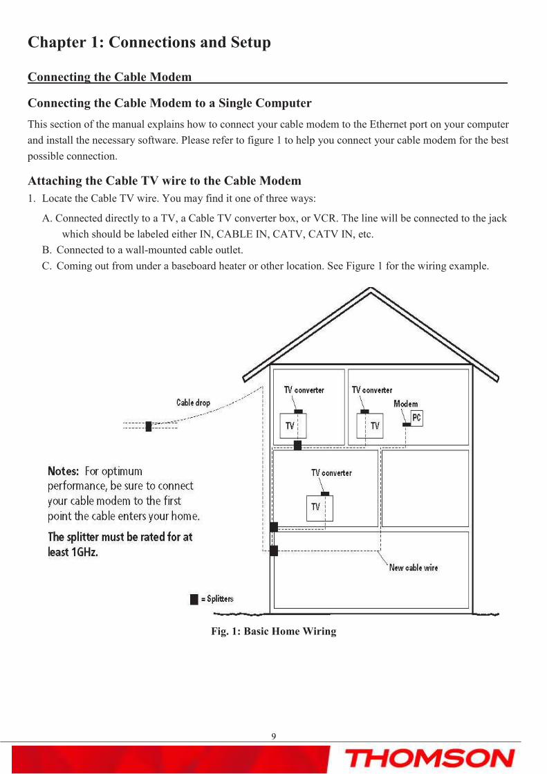
Attaching the Cable TV wire to the Cable Modem
1. Locate the Cable TV wire. You may find it one of three ways:
A. Connected directly to a TV, a Cable TV converter box, or VCR. The line will be connected to the jack
which should be labeled either IN, CABLE IN, CATV, CATV IN, etc.
B. Connected to a wall-mounted cable outlet.
C. Coming out from under a baseboard heater or other location. See Figure 1 for the wiring example.
Fig. 1: Basic Home Wiring

Chapter 1: Connections and Setup
10
Important Connection Information
The cable modem supports Ethernet connections simultaneously
Ethernet Connection to One Computer
Make the connections to the modem in the following sequence:
1. Connect one end of the coaxial cable to the cable connection in the wall, and the other end to the connector
on the modem labeled “CABLE.”
2. Insert the plug from the AC power supply into the power AC jack on the cable modem and the two-prong
plug into the AC outlet.
Note: Use only the power supply that accompanied this unit. Using other adapters may damage the unit.
3. Connect one end of the Ethernet cable (straight-wired, see below) to the Ethernet port on the back of your
computer, and the other end to the ETHERNET port on the cable modem’s back panel.
Make sure that the Ethernet cable is straight-wired (not “null” or crossover-wired). However, you will need
a crossover-type cable if you are connecting the modem to a hub, or a hub within a port switch that provides
the same function.
Fig. 2

Chapter 1: Connections and Setup
11
Connecting More Than One Computer to the Cable Modem
If you need to connect more than two computers or if you need to connect two computers, you’ll need the
following additional equipment (if supported by your cable operator):
• Crossover-wired, or “null,” category 5 Ethernet cable for the cable modem to be connected to the hub
• 10/100/1000BaseT Hub or Switch
• Straight through, or standard, category 5 Ethernet cable (one for each computer to be connected)
If you have a hub with an uplink port, a straight through cable can be used in combination with that port in lieu
of the crossover cable.
An uplink port has a small switch on it to change the polarity of the connection. It can accept either a crossover
or a straight cable, depending on the setting.
Fig. 3
NoteNoteNoteNote: You may need to check with your service provider in order to connect multiple computers.

Chapter 1: Connections and Setup
12
Telephone or Fax Connection When properly connected, most telephony devices can be used with the EMTA just as with conventional
telephone service. To make a normal telephone call, pick up the handset; listen for a dial tone, then dial the
desired number. For services such as call waiting, use the hook switch (or FLASH button) to change calls. The
following procedures describe some of the possible connection schemes for using telephony devices with the
EMTA.
1. Connect a standard phone line cord directly from the phone (fax machine, answering machine, caller ID box, etc.) to one of the LINE jacks on the EMTA.
2. If there is a phone line in your home which is NOT connected to another telephone service provider, connect a standard phone line cord from a jack on this line to one of the LINE jacks of the EMTA. Connect
a standard phone line cord directly from the phone (fax machine, answering machine, caller ID box, etc.) to
one of the other jacks in the house that uses that line.
3. If you have a multi-line telephone, connect a standard phone line cord (not an RJ-14 type line cord) from the phone to the LINE jacks on the EMTA. (Other phones can be added to each line by using standard
phone line splitters.
Fig. 4: Phone/Fax Connection
Chapter 1: Connections and Setup
13
Activating the Cable Modem
If there is no lighted LEDs on the front panel, check the power on/off switch position on the back panel of
cable modem: it must be ”ON” = “1”.
After you install the cable modem and turn it on for the first time (and each time the modem is reconnected to
the power), it goes through several steps before it can be used. Each of these steps is represented by a different
pattern of flashing lights on the front of the modem.
Note: All indicators flash once prior to the initialization sequence.
If all of the lights are flashing sequentially, it means the cable modem is automatically updating its system
software. Please wait for the lights to stop flashing. You cannot use your modem during this time. Do not
remove the power supply, switch off (on/off switch) or reset the cable modem during this process.
Activating the EMTAActivating the EMTAActivating the EMTAActivating the EMTA
After you install the EMTA and turn it on for the first time (and each time the modem is reconnected to the
power), it goes through several steps before it can be used. Each of these steps is represented by a different
pattern of flashing lights on the front of the modem.
Note: All indicators flash once prior to the initialization sequence.
If all of the lights are flashing sequentially, it means the EMTA is automatically updating its system software.
Please wait for the lights to stop flashing. You cannot use your modem during this time. Do not remove the
power supply or reset the EMTA during this process.
To make sure that you can access the Internet successfully, please check the following first.
1. Make sure the connection (through Ethernet) between the EMTA and your computer is OK.
2. Make sure the TCP/IP protocol is set properly.
3. Subscribe to a Cable Company.
Accessing Accessing Accessing Accessing the the the the InternetInternetInternetInternet
If enabled by your service provider; please proceed as follows:
1. Once your host PC is properly configured.
2. Start your web browser and type the private IP address of the EMTA on the URL field:
192.168.100.1.
3. After connecting to the URL, you can see the basic status of this device. The web pages display
information about basic LAN, Hardware info, event log, and CM state.

Chapter 1: Connections and Setup
14
Basic Status Web Page GroupBasic Status Web Page GroupBasic Status Web Page GroupBasic Status Web Page Group
Basic LAN
The screen will be shown as below. This page displays the RF parameters, the status of the EMTA and the
interface parameters.

Chapter 1: Connections and Setup
15
Hardware Info
This page offers the hardware info for this device, containing the system information, MTA serial number,
firmware name and build time, and so on.
Event Log
This page records the event log for DOCSIS and PacketCable.
You can clear the logs by pressing the “Clear Log” button.

Chapter 1: Connections and Setup
16
CM State
You can find the EMTA state on this page.

Chapter 1: Connections and Setup
17
Initial Scan
To speed up the modem’s first time startup, enter known downstream frequency and/or upstream channel ID information
here. Then click “Apply” button to start scanning the cable network beginning with the values supplied here.
Chapter 2: Additional Information
18
Chapter 2: Additional Information
Frequently Asked Questions
Q. What if I don’t subscribe to cable TV?
A. If cable TV is available in your area, data service may be made available with or without cable TV service.
Contact your local cable company for complete information on cable services, including high-speed internet
access.
Q. How do I get the system installed?
A. Professional installation from your cable provider is strongly recommended. They will ensure proper cable
connection to the modem and your computer. However, your retailer may have offered a self installation kit,
including the necessary software to communicate with your cable ISP.
Q. My modem is connected to the power sector but does not work
A.Check the ON/OFF switch on the rear panel of your modem. Should be set to “1”
Q. Once my cable modem is connected, how do I get access to the Internet?
A. Your local cable company provides your internet service*, offering a wide range of services including
email, chat, and news and information services, and a connection to the World Wide Web.
Q. Can I watch TV and surf the Internet at the same time?
A. Absolutely!
Q. Can I run more than one computer on the modem?
A. Yes – a single cable modem can support up to 32 computers using Ethernet connectivity.
Q. What do you mean by “Broadband”?
A. Simply put, it means you’ll be getting information through a “bigger pipe,” with more bandwidth, than
a standard phone line can offer. A wider, “broader” band means more information, more quickly.
Q. What is DOCSIS and what does it mean?
A. “Data Over Cable Service Interface Specifications” is the industry standard that most cable companies are
adopting as they upgrade their systems. Should you ever decide to move, the DOCSIS cable modem will
work with all upgraded cable systems that is DOCSIS compliant.
Q. What is Euro-DOCSIS and what does it mean?
A. Euro-DOCSIS is the modified DOCSIS standard to accommodate European cable systems which often use
8 MHz channel spacing cable networks.

Chapter 2: Additional Information
19
General Troubleshooting
You can correct most problems you have with your product by consulting the troubleshooting list that follows.
I can’t access the internet.
� Check all of the connections to your modem.
� Your Ethernet card may not be working. Check each product’s documentation for more information.
� The Network Properties of your operating system may not be installed correctly or the settings may be
incorrect. Check with your ISP or cable company.
Two lights are flashing in sequence (DS & US) while 2 others are on (Power & Online).
� This means the modem is automatically updating its system software. Please wait for the lights to stop
flashing. The updating process typically lasts less than one minute.
� Do not remove the power supply or reset the modem during this process.
I can’t get the modem to establish an Ethernet connection.
� Even new computers don’t always have Ethernet capabilities – be sure to verify that your computer has a
properly installed Ethernet card and the driver software to support it.
� Check to see that you are using the right type of Ethernet cable.
The modem won’t register a cable connection (Online light not on continuously).
� If the modem is in Initialization Mode, the ONLINE lights will be flashing. Call your Cable Company if it
has not completed this 5-step process within 30 minutes, and note which step it is getting stuck on. The
modem should work with a standard RG-6 coaxial cable, but if you’re using a cable other than the one
your Cable Company recommends, or if the terminal connections are loose, it may not work. Check with
your Cable Company to determine whether you’re using the correct cable.
� If you subscribe to video service over cable, the cable signal may not be reaching the modem. Confirm
that good quality cable television pictures are available to the coaxial connector you are using by
connecting a television to it. If your cable outlet is “dead”, call your Cable Company.
� Verify that the Cable Modem service is DOCSIS/ Euro-DOCSIS compliant by calling your cable provider.

Chapter 2: Additional Information
20
FCC Declaration of Conformity and Industry Canada Information
This device complies with Part 15 of the FCC Rules. Operation is subject to the following two conditions: (1)
this device may not cause harmful interference, and (2) this device must accept any interference received,
including interference that may cause undesired operation.
Trade Name: Model: THG571
Equipment Classification: Computing Device Accessory
Responsible Party: Thomson Inc.
101 W. 103rd St. INH700
Indianapolis, IN 46290
USA
This equipment has been tested and found to comply with the limits for a Class B digital device, pursuant to
Part 15 of the FCC Rules. These limits are designed to provide reasonable protection against harmful
interference in a residential installation. This equipment generates, uses, and can radiate radio frequency
energy and, if not installed and used in accordance with the instructions, may cause harmful interference to
radio communications. However there is no guarantee that interference will not occur in a particular
installation. If this equipment does cause harmful interference to radio or television reception, which can be
determined by turning the equipment off and on, the user is encouraged to try and correct the interference by
one or more of the following measures:
• Reorient or relocate the receiving antenna.
• Increase the separation between the equipment and receiver.
. • Connect this equipment into an outlet on a circuit different from that to which the receiver is
. connected.
. • Consult the dealer or an experienced radio/TV technician for help.
FCC regulations state that unauthorized changes or modifications to this equipment may void the user’s
authority to operate it.
This Class B digital apparatus meets all requirements of the Canadian Interference Causing Equipment
Regulations.
Service Information
If you purchased or leased your cable modem directly from your cable company, then warranty service for the
cable modem may be provided through your cable provider or its authorized representative. For information
on 1) Order Service, 2) Obtaining Customer Support, or 3) Additional Service Information, please contact your
cable company. If you purchased your cable modem from a retailer, see the enclosed warranty card.

Chapter 2: Additional Information
21
Glossary
10/100/1000BaseT – Unshielded, twisted pair cable with an RJ-45 connector, used with Ethernet LAN
(Local Area Network). “10/100/1000” indicates auto-sensing speed (10 Mbps and 100 Mbps and 1Gbps),
“Base” refers to baseband technology,and “T” means twisted pair cable
.
DHCP (Dynamic Host Control Protocol) – A protocol which allows a server to dynamically
assign IP addresses to workstations on the fly.
DOCSIS (Data Over Cable Service Interface Specifications) – A project with the objective of developing a
set of necessary specifications and operations support interface specifications for cable modems and
associated equipment.
Ethernet card – A plug-in circuit board installed in an expansion slot of a personal computer. The
Ethernet card (sometimes called a Network Interface Card or NIC) takes parallel data from the
computer, converts it to serial data, puts it into a packet format, and sends it over the 10BaseT or
100BaseT or 1000BaseT LAN cable.
F Connector – A type of coaxial connector, labeled CABLE IN on the rear of the cable modem,
that connects the modem to the cable system.
HTTP (HyperText Transfer Protocol) – Invisible to the user, HTTP is used by servers and
clients to communicate and display information on a client browser.
Hub – A device used to connect multiple computers to the cable modem.
IP Address – A unique, 32-bit address assigned to every device in a network. An IP (Internet
Protocol) address has two parts: a network address and a host address. This modem receives a
new IP address from your cable operator via DHCP each time it goes through Initialization Mode.
MAC Address – The permanent “identity” for a device programmed into the Media Access
Control layer in the network architecture during the modem’s manufacture.
Network Driver – A file that is loaded on the computer to allow the computer to recognize the
Ethernet card.
TCP/IP (Transmission Control Protocol/Internet Protocol) – A networking protocol that
provides communication across interconnected networks, between computers with diverse
hardware architectures and various operating systems.
Chapter 2: Additional Information
22
Applicable power supplies list:
a ) Leader Electronics Inc.
MV18-Y120150-A2 (China plug)
MV18-Y120150-A3 (Australia plug)
MV18-Y120150-B2 (United Kingdom plug)
MV18-Y120150-C4 (Korea plug)
MV18-Y120150-C5 (Europe plug)
b ) Global Yeou Diann Electric Industrial Co., Ltd.
AMS6-1201500SSH (Australian plug)
AMS6-1201500SBH (United kingdom plug)
AMS6-1201500SKH (Korea plug)
AMS6-1201500SCH (China plug)
AMS6-1201500SXH (Brazil plug)
AMS6-1201500SRH (Russia plug)
AMS6-1201500SAH (Argentina plug)
AMS6-1201500SVH (European & Singapore plug)
AMS6-1201500SHH (Thailand plug)
Please do not send any products to the Indianapolis address listed in this manual or on the carton. This will
only add delays in service for your product.
Thomson Inc.
101 W. 103rd St., INH700
Indianapolis, IN 46290
USA

© 2007 Thomson Inc.- Trademark(s) ® registered\ -Marca(s) registada(s)\Photos and features subject to change without notice.Illustration of product finish may vary from actual color.
For more informationTechnicolor | 1 rue Jeanned'Arc | 92443 Issy les Moulineaux | FranceTel. : �� (0) 1 41 86 50 00 | Fax : �� (0) 1 41 86 56 59 | www.thomson-broadband.com