user manual tp01 - hukseflux€¦ · tp01 manual v1627 5/35 introduction tp01 is a sensor for...
TRANSCRIPT

Copyright by Hukseflux | manual v1627 | www.hukseflux.com | [email protected]
USER MANUAL TP01 Thermal properties sensor
HuksefluxThermal Sensors
TP01 manual v1627 2/35
Warning statements
Putting more than 2 Volt across the sensor wiring can lead to permanent damage to the sensor. Putting more than 2 Volt across the heater wiring can lead to permanent damage to the heater. Do not use “open circuit detection” when measuring the sensor output. If power to the heater is supplied from a 12 VDC source, you must put a 150 Ω resistor in series with the heater.
TP01 manual v1627 3/35
Contents Warning statements 2 Contents 3 List of symbols 4 Introduction 5 1 Ordering and checking at delivery 8 1.1 Ordering TP01 8 1.2 Included items 8 1.3 Quick instrument check 8 2 Instrument principle and theory 9 2.1 General theory 9 2.2 Thermal conductivity measurement 10 2.3 Soil thermal conductivity for several soil types 11 2.4 Thermal diffusivity measurement 11 2.5 Volumic heat capacity measurement 12 2.6 Measuring the storage term in soil heat flux measurement 12 2.7 Trend monitoring of soil water content 13 2.8 Calibration 13 2.9 Programming 14 3 Specifications of TP01 16 3.1 Dimensions of TP01 19 4 Standards and recommended practices for use 20 5 Installation of TP01 21 5.1 Site selection and installation 21 5.2 Electrical connection 22 5.3 Requirements for data acquisition / amplification 24 6 Making a dependable measurement 25 6.1 Uncertainty evaluation 25 6.2 Typical measurement uncertainties 25 6.3 Contributions to the uncertainty budget 26 7 Maintenance and trouble shooting 28 7.1 Recommended maintenance and quality assurance 28 7.2 Trouble shooting 29 7.3 TP01 calibration 30 8 Appendices 32 8.1 Appendix on cable extension / replacement 32 8.2 Appendix on preparation of agar gel for calibration 32 8.3 Appendix on use of TP01 beyond its rated measurement range 33 8.4 EU declaration of conformity 34

TP01 manual v1627 4/35
List of symbols Quantities Symbol Unit Thermal conductivity λ W/(m∙K) Voltage output U V Voltage output as a function of heating time U (t) V Voltage output difference ΔU V Sensitivity S V/K Heating power per meter Q W/m Heater length L m Temperature T °C Temperature difference ΔT °C, K Time constant τ s Time t s Volumic heat capacity cvolumic J/(m³∙K) Resistance R Ω Storage term S W/m² Depth of installation x m Water content (on mass basis) θm kg/kg Water content (on volume basis) θv m³/m³ Subscripts property of thermopile sensor sensor property obtained under calibration reference reference conditions property at the (soil) surface surface property of the surrounding soil soil property of the heater heater

TP01 manual v1627 5/35
Introduction TP01 is a sensor for long-term monitoring of soil thermal conductivity. A measurement with TP01 may also be used to estimate the soil thermal diffusivity and volumic heat capacity, leading to a better understanding of dynamic (variable heat flux) thermal behaviour of soils. TP01 is designed for long-term use at one measurement location. Applied in meteorological surface flux measurement systems, TP01 improves the estimates of soil heat flux and of the so-called storage term (see the paragraph about the storage term). The sensor, combining a heater and a temperature-difference sensor with a high sensitivity and an extremely low thermal mass, is a proprietary Hukseflux design. The sensor inside TP01 is a temperature-difference sensor consisting of 2 thermopiles. It measures the radial temperature difference around a heating wire with a record breaking sensitivity. Both the heating wire and the sensor are incorporated in a very thin plastic foil. TP01 measures soil thermal conductivity. It is designed for long-term on-site operation, buried in the soil. Its rated operating range is 0.3 to 4 W/(m∙K), which covers most inorganic soil types. The low thermal mass of TP01 also makes it suitable for measuring the soil thermal diffusivity and the volumic heat capacity. The thermal conductivity, λ, in W/(m·K), is calculated by dividing the TP01 sensitivity, S, by the sensor output, a small voltage difference ΔU which is a response to stepwise heating, and multiplying by the applied electrical power Q per meter heating wire. The measurement function of TP01 is: λ = S·Q/ ΔU (Formula 0.1) The factory-determined sensitivity S, as obtained under calibration reference conditions, is provided with TP01 on its product certificate. TP01 calibration is traceable to international standards. The recommended calibration interval of TP01 is 2 years. Thermal diffusivity and volumic heat capacity are estimated from time response to stepwise heating. These measurements are optional. The volumic heat capacity is a linear function of soil water content and you may use TP01 measurements to monitor trends in soil water content. Contrary to many other soil water content sensors, TP01 is not sensitive to contamination by salts and the measurement still functions in electrically conducting saline or fertilised soils. TP01 should be incorporated in the user's measurement and control system. It can be connected directly to commonly used data logging systems. Typically every 6 hours, the TP01 heater is switched on to perform a measurement. A typical TP01 is part of a meteorological surface flux measurement system in which also wind, humidity, soil heat flux, soil temperatures at different depths and net-radiation are
TP01 manual v1627 6/35
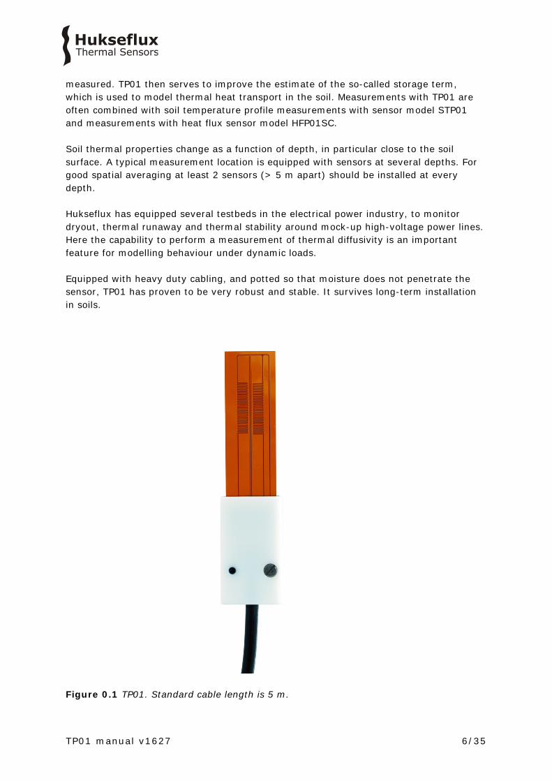
measured. TP01 then serves to improve the estimate of the so-called storage term, which is used to model thermal heat transport in the soil. Measurements with TP01 are often combined with soil temperature profile measurements with sensor model STP01 and measurements with heat flux sensor model HFP01SC. Soil thermal properties change as a function of depth, in particular close to the soil surface. A typical measurement location is equipped with sensors at several depths. For good spatial averaging at least 2 sensors (> 5 m apart) should be installed at every depth. Hukseflux has equipped several testbeds in the electrical power industry, to monitor dryout, thermal runaway and thermal stability around mock-up high-voltage power lines. Here the capability to perform a measurement of thermal diffusivity is an important feature for modelling behaviour under dynamic loads. Equipped with heavy duty cabling, and potted so that moisture does not penetrate the sensor, TP01 has proven to be very robust and stable. It survives long-term installation in soils.
Figure 0.1 TP01. Standard cable length is 5 m.

TP01 manual v1627 7/35
See also: • STP01 soil temperature profile sensor • for laboratory use, models TP02 and TP08 are available. Turn key measuring systems
are TPSYS02, FTN02 and MTN02. • Hukseflux sensors for surface flux measurement • heat flux sensors HFP01 and HFP01SC
Figure 0.2 TP01 thermal properties sensor. The thermopile sensor (1) and heating wire (2) are both incorporated in a thin plastic foil. The cable (3) is 5 m long in the standard configuration and may be extended to 50 m.
20
4
2060
1
31.2.3.4.5.6.
0.15

TP01 manual v1627 8/35
1 Ordering and checking at delivery
1.1 Ordering TP01
The standard configuration of TP01 is with 5 metres cable. Common options are: • longer cable in multiples of 5 m, cable lengths above 20 m in multiples of 10 m.
specify total cable length.
1.2 Included items
Arriving at the customer, the delivery should include: • thermal properties sensor TP01 • cable of the length as ordered • product certificate matching the instrument serial number
1.3 Quick instrument check
A quick test of the instrument can be done by connecting it to a multimeter. 1. Check the electrical resistance of the sensor and heater according to table 5.2.2. Use a multimeter at the 100 Ω range. The typical resistance of the wiring is 0.1 Ω/m (added value of 2 wires). Infinite resistance indicates a broken circuit; zero or a lower than 1 Ω resistance indicates a short circuit. 2. Check if the sensor reacts to heat: put the multimeter at its most sensitive range of DC voltage measurement, typically the 100 x 10-3 VDC range or lower. Activate the TP01 heater by putting 1 to 2 VDC across the brown and yellow wires. Use a 1.5 V battery. Put the sensor in soil or another granular material. The signal between the green and white output should read > 1 x 10⁻³ V now. It will vary if the sensor moves. 3. Inspect the instrument for any damage. 4. Check the sensor serial number, and sensitivity on the cable labels (one at sensor end, one at cable end) against the product certificate provided with the sensor.
TP01 manual v1627 9/35
2 Instrument principle and theory TP01 measures the thermal conductivity [λ] of the surrounding environment. It has a rated measurement range of 0.3 to 5 W/(m·K) which makes it suitable for use in most soils. A requirement for an accurate measurement is that there is good thermal contact between soil and sensor. You must incorporate TP01 in your own measurement and control system. For thermal conductivity measurement this system should perform 2 x voltage readout, and power supply switching. For thermal diffusivity and volumic heat capacity the sensor response time must be measured. Advantages of using TP01 are: • high sensitivity (good signal to noise ratio in low-flux environments, low use of
power) • low thermal mass (allows for a quick measurement and the ability to measure
thermal diffusivity and heat capacity) • robustness, including a strong cable (essential for permanently installed sensors) • IP protection class: IP67 (essential for outdoor application) • low electrical resistance (low pickup of electrical noise)
2.1 General theory
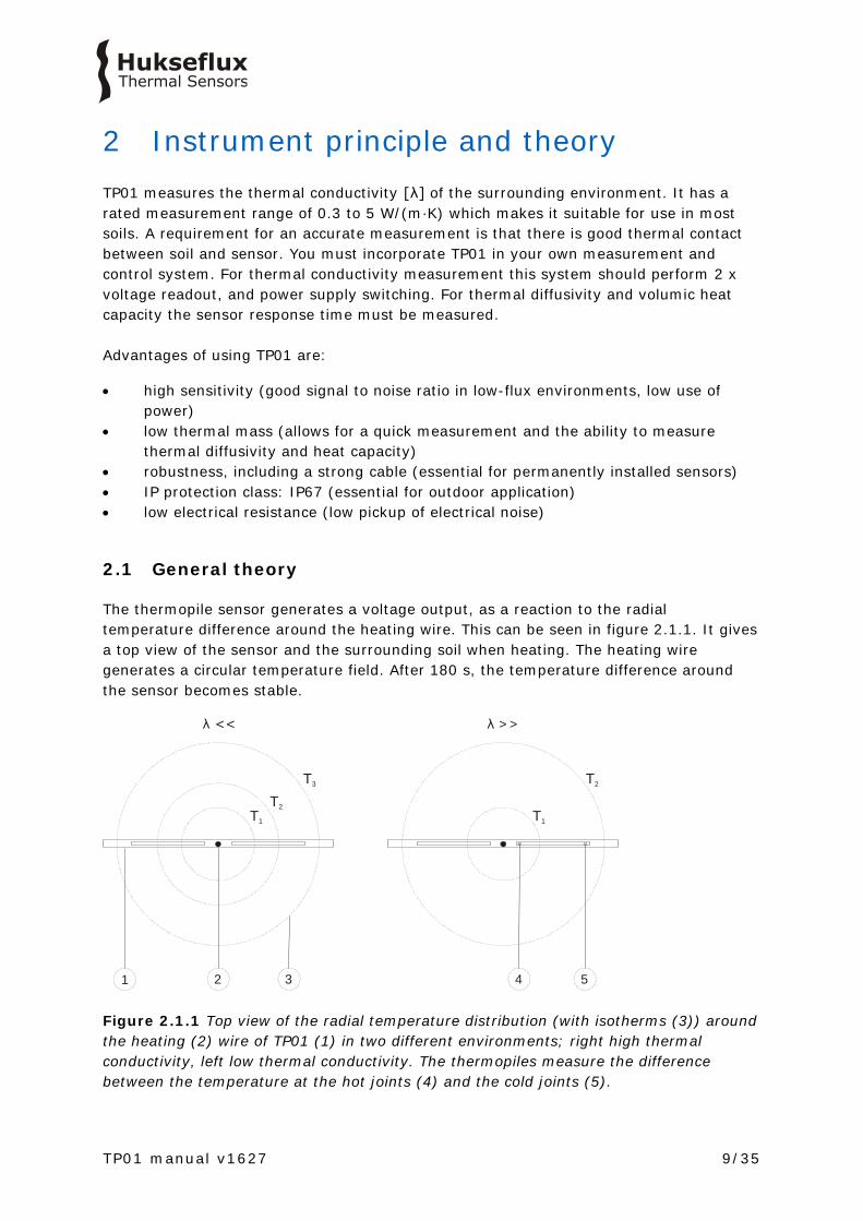
The thermopile sensor generates a voltage output, as a reaction to the radial temperature difference around the heating wire. This can be seen in figure 2.1.1. It gives a top view of the sensor and the surrounding soil when heating. The heating wire generates a circular temperature field. After 180 s, the temperature difference around the sensor becomes stable.
Figure 2.1.1 Top view of the radial temperature distribution (with isotherms (3)) around the heating (2) wire of TP01 (1) in two different environments; right high thermal conductivity, left low thermal conductivity. The thermopiles measure the difference between the temperature at the hot joints (4) and the cold joints (5).
T3
T2T1
T2
T1
21 3 4 5
λ >>λ <<

TP01 manual v1627 10/35
U
tU ~ 1/λt ~ a
λ < λ1 1, a > a
λ = λ1 1, a < a
λ > λ1 1, a = a
Figure 2.1.2 TP01 signal in different soil types: the signal amplitude varies with [1/λ], the response time varies with thermal diffusivity [a]
2.2 Thermal conductivity measurement
The measurement principle of TP01 relies on measurement of the radial temperature difference around a heating wire. The temperature difference is measured by two thermopiles connected in series, generating a single output. Both the heater and the thermopile are incorporated in a thin plastic foil. The thermal conductivity, λ, in W/(m·K), is calculated by dividing the TP01 sensitivity, S, by the output, a small voltage difference ΔU which is a response to stepwise heating, and multiplying by the applied electrical power Q per meter heating wire. The measurement function of TP01 is: λ = S·Q/ ΔU (Formula 0.1) The voltage difference ΔU is determined by performing a measurement just before the heating starts and after heating for 180 s. ΔU = U (180) – U (0) (Formula 2.2.1) The factory-determined sensitivity S, as obtained under calibration reference conditions, is provided with TP01 on its product certificate. The heating power Q, in W/m, is determined from a voltage measurement across the heater and taking the heater length and electrical resistance into account.

TP01 manual v1627 11/35
2.3 Soil thermal conductivity for several soil types
Data for the following graph is taken from IEEE standard 442 – IEEE guide for Soil Thermal Resistivity Measurements”, figure 3. It gives orders of magnitude of the thermal conductivity for different soil types as a function of water content.
Figure 2.3.1 Typical soil thermal conductivity values for different soil types as a function of water content.
2.4 Thermal diffusivity measurement
The low thermal mass of the total TP01 sensor makes it suitable for estimating thermal diffusivity [a]. Dividing [λ] by the thermal diffusivity [a] gives the volumic heat capacity [cvolumic] which varies with water content. Thermal diffusivity and volumic heat capacity may be estimated from the response time to stepwise heating. The output response of TP01 to stepwise heating is: ΔU = (S·Q/ λ) · F[a·t] (Formula 2.4.1) With [t] time, [a] thermal diffusivity, and F a function that equals 1 at large values of [a·t] and 0 at the start of the heating interval. Formula 2.4.1 shows that the step response of the sensor signal scales with [Q/ λ] for the amplitude, and with [a] for the time response.

TP01 manual v1627 12/35
By curve fitting F you can determine [a]. One of the easiest ways of doing this is looking at the 63 % response time of the measurement. The common procedure is to first determine the thermal conductivity, and during the settling interval after the heating interval to determine how much time it takes to arrive at 37 % of the ΔU amplitude. The thermal diffusivity is measured by comparing the TP01 response time during the measurement to that under calibration reference conditions. The calibration reference conditions include a thermal diffusivity of 0.14 10-6 m2 /s. a reference = 0.14 10-6 The 63 % response time for the determination of the thermal diffusivity is 19 s. τ reference = 19 The measurement equation for the thermal diffusivity is: a = a reference · τ reference / τ (Formula 2.4.2)
2.5 Volumic heat capacity measurement
The volumic heat capacity is determined from cvolumic = λ/a (Formula 2.5.1)
2.6 Measuring the storage term in soil heat flux measurement
In meteorological experiments one of the measured parameters is heat flux in the soil. For practical reasons this is done at 0.05 m depth. There is no simple solution for direct measurement of soil heat flux at the soil surface, which is the parameter that must eventually be estimated. The flux at the soil surface Φsurface is usually estimated from the flux measured by the heat flux sensor buried at a depth of around 0.05 m plus the change of the energy stored in the layer above the sensor during the measuring interval t1 to t2. Φsurface = Φ0.05 m + S (Formula 2.6.1) The quantity S is called the storage term. The storage term is calculated from a space-averaged soil temperature measurement, using multiple soil temperature sensors, and an estimate of the volumic heat capacity cvolumic of the soil above the sensor. S = (T(t1) - T(t2))·cvolumic·x/(t1 - t2) (Formula 2.6.2) Where T(t1) - T(t2) is the temperature difference in the measurement interval, x the depth of installation of the soil heat flux sensors.

TP01 manual v1627 13/35
A correct estimate of Φsurface with a high time resolution requires a low depth of installation and a correct estimate of the storage term. At an installation depth of 0.05 m, the storage term typically represents up to 50 % of the total Φsurface. When the temperature T is measured closely below the surface, the response time of the storage term to a changing Φsurface is in the order of magnitude of 20 min, while the heat flux sensor buried at twice the depth is a factor 5 slower (square of the depth). The volumic heat capacity is estimated from the specific heat capacity of dry soil, csoil, dry, the bulk density of the dry soil ρ, the water content on mass basis Q, on a volume basis Qv, and cwater, the specific heat capacity of water. cvolumic = ρsoil·(csoil, dry + θm ·cwater) = ρsoil·csoil, dry + ρwater· θv ·cwater (Formula 2.6.3) The heat capacity of water is known, but the other quantities of the equation are difficult to determine and vary with location and time. The storage term may be the main source of uncertainty in the soil energy balance measurement. With TP01 the estimate of the volumic heat capacity is much simpler: cvolumic = λ/a (Formula 2.5.1)
2.7 Trend monitoring of soil water content
In a certain soil type there are direct and linear relationships between the soil water content by mass or volume and the volumic heat capacity. TP01 can therefore be used to monitor trends of soil water content even without detailed knowledge of soil dry densities and heat capacities. θm = ((cvolumic / ρsoil )- csoil, dry )) / cwater (Formula 2.7.1) For estimates on a volume basis, one has to multiply by ρsoil and divide by ρwater: θv = (cvolumic - csoil, dry ρsoil) / ρwater cwater (Formula 2.7.2)
2.8 Calibration
TP01 factory calibration is traceable from SI. TP01 is calibrated by a thermal conductivity measurement in a calibration reference material, and by performing an electrical resistance measurement. The test method is not standardised. The calibration reference material is a verified intrinsic measurement standard (vocabulary according to ISO Guide 99), an agar gel, which has thermal properties similar to water. The agar gel is characterised by a reference thermal needle, which is traceable to length and electrical resistance. The TP01 heater electrical resistance is traceable to current and voltage standards.
TP01 manual v1627 14/35
2.9 Programming
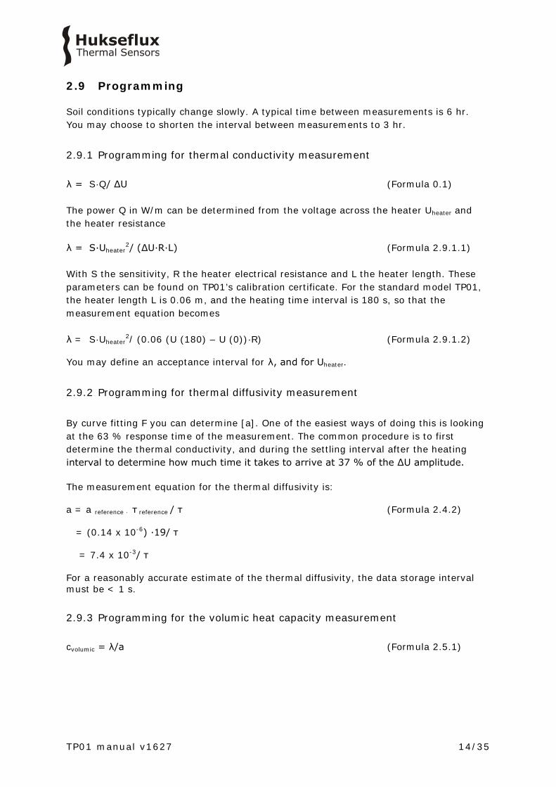
Soil conditions typically change slowly. A typical time between measurements is 6 hr. You may choose to shorten the interval between measurements to 3 hr.
2.9.1 Programming for thermal conductivity measurement λ = S·Q/ ΔU (Formula 0.1) The power Q in W/m can be determined from the voltage across the heater Uheater and the heater resistance λ = S·Uheater
2/ (ΔU·R·L) (Formula 2.9.1.1) With S the sensitivity, R the heater electrical resistance and L the heater length. These parameters can be found on TP01’s calibration certificate. For the standard model TP01, the heater length L is 0.06 m, and the heating time interval is 180 s, so that the measurement equation becomes λ = S·Uheater
2/ (0.06 (U (180) – U (0))·R) (Formula 2.9.1.2) You may define an acceptance interval for λ, and for Uheater.
2.9.2 Programming for thermal diffusivity measurement By curve fitting F you can determine [a]. One of the easiest ways of doing this is looking at the 63 % response time of the measurement. The common procedure is to first determine the thermal conductivity, and during the settling interval after the heating interval to determine how much time it takes to arrive at 37 % of the ΔU amplitude. The measurement equation for the thermal diffusivity is: a = a reference · τ reference / τ (Formula 2.4.2) = (0.14 x 10-6) ·19/ τ = 7.4 x 10⁻³/ τ For a reasonably accurate estimate of the thermal diffusivity, the data storage interval must be < 1 s.
2.9.3 Programming for the volumic heat capacity measurement cvolumic = λ/a (Formula 2.5.1)
TP01 manual v1627 15/35
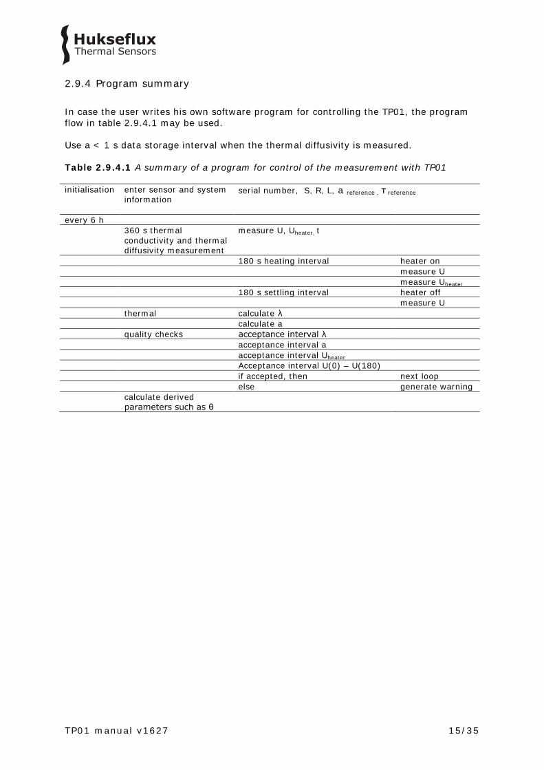
2.9.4 Program summary In case the user writes his own software program for controlling the TP01, the program flow in table 2.9.4.1 may be used. Use a < 1 s data storage interval when the thermal diffusivity is measured. Table 2.9.4.1 A summary of a program for control of the measurement with TP01 initialisation enter sensor and system
information
serial number, S, R, L, a reference , τ reference
every 6 h 360 s thermal
conductivity and thermal diffusivity measurement
measure U, Uheater, t
180 s heating interval heater on measure U measure Uheater 180 s settling interval heater off measure U thermal calculate λ calculate a quality checks acceptance interval λ acceptance interval a acceptance interval Uheater Acceptance interval U(0) – U(180) if accepted, then next loop else generate warning calculate derived
parameters such as θ

TP01 manual v1627 16/35
3 Specifications of TP01 TP01 measures the thermal conductivity [λ] of its surrounding environment. It is designed for long-term monitoring of soils. It has a rated measurement range of 0.3 to 5 W/(m·K) which makes it suitable for use in most (inorganic) soils. It is also used for measurement of thermal diffusivity and volumic heat capacity. Good thermal contact between soil and sensor is required. TP01 can only be used in combination with a suitable measurement and control system. Table 3.1 Specifications of TP01 (continued on next page) TP01 SPECIFICATIONS Sensor type thermal properties sensor Measurand thermal conductivity Rated operating environment surrounded by soil
non-organic, saline and non-saline, fertilised and non-fertilised soils
Measurand in SI units thermal conductivity in W/(m·K) Measurement range 0.3 to 5 W/(m·K) Optional non-traceable measurand thermal diffusivity Measurand in SI units thermal diffusivity in m2/s) Measurement range (0.05 to 1 ) x 10-6 m2/s Optional non-traceable measurand volumic heat capacity Measurand in SI units volumic heat capacity in J/(kg·K) Optional trend monitoring soil water content Measurand in SI units water content in kg/kg or m3/m3 Measurement principle radial temperature difference measurement around a
heating wire using a thermopile sensor Sensitivity 150 x 10-6 V/K (nominal) Expected voltage output -1 to 1 x 10⁻³ V (thermopile sensor)
0 to 1.5 VDC (heater) Required programming measurement of thermal conductivity
optionally measurement of thermal diffusivity and volumic heat capacity
Measurement function / required programming
λ = S·Q/ ΔU
Optional measurement function/ optional programming
a = a reference · τ reference / τ
Optional measurement function/ optional programming
cvolumic = λ/a
Required readout and control thermopile sensor and heater: 2 x differential voltage channel or 2 x single ended voltage channel, input resistance > 106 Ω heater: 1 x switchable power 1 - 2 VDC
Required uncertainty 10 x 10-6 V at 10-3 V 5 x 10⁻³ V at 2 V
Rated operating temperature range -30 to +80 °C Temperature dependence < 0.1 %/°C Time constant in agar gel calibration reference material
19 s (nominal)
Non-stability < 1 %/yr
TP01 manual v1627 17/35
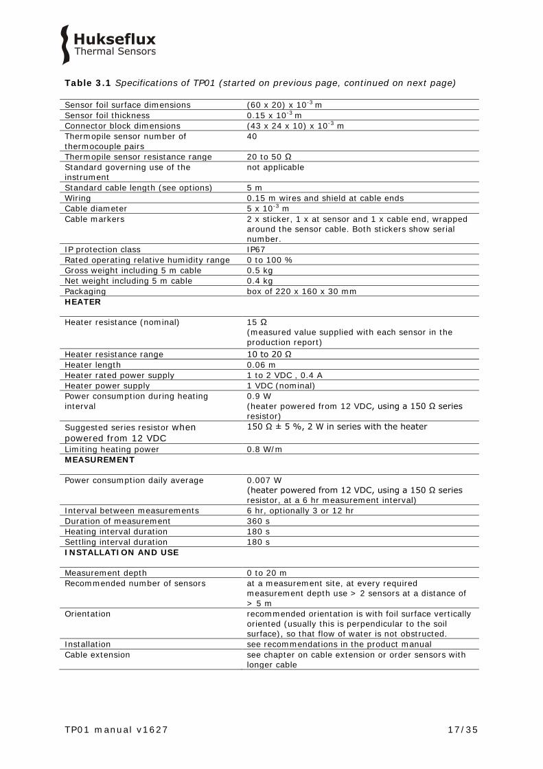
Table 3.1 Specifications of TP01 (started on previous page, continued on next page) Sensor foil surface dimensions (60 x 20) x 10-3 m Sensor foil thickness 0.15 x 10⁻³ m
Connector block dimensions (43 x 24 x 10) x 10-3 m Thermopile sensor number of thermocouple pairs
40
Thermopile sensor resistance range 20 to 50 Ω Standard governing use of the instrument
not applicable
Standard cable length (see options) 5 m Wiring 0.15 m wires and shield at cable ends Cable diameter 5 x 10⁻³ m Cable markers 2 x sticker, 1 x at sensor and 1 x cable end, wrapped
around the sensor cable. Both stickers show serial number.
IP protection class IP67 Rated operating relative humidity range 0 to 100 % Gross weight including 5 m cable 0.5 kg Net weight including 5 m cable 0.4 kg Packaging box of 220 x 160 x 30 mm HEATER Heater resistance (nominal) 15 Ω
(measured value supplied with each sensor in the production report)
Heater resistance range 10 to 20 Ω Heater length 0.06 m Heater rated power supply 1 to 2 VDC , 0.4 A Heater power supply 1 VDC (nominal) Power consumption during heating interval
0.9 W (heater powered from 12 VDC, using a 150 Ω series resistor)
Suggested series resistor when powered from 12 VDC
150 Ω ± 5 %, 2 W in series with the heater
Limiting heating power 0.8 W/m MEASUREMENT Power consumption daily average 0.007 W
(heater powered from 12 VDC, using a 150 Ω series resistor, at a 6 hr measurement interval)
Interval between measurements 6 hr, optionally 3 or 12 hr Duration of measurement 360 s Heating interval duration 180 s Settling interval duration 180 s INSTALLATION AND USE
Measurement depth 0 to 20 m Recommended number of sensors at a measurement site, at every required
measurement depth use > 2 sensors at a distance of > 5 m
Orientation recommended orientation is with foil surface vertically oriented (usually this is perpendicular to the soil surface), so that flow of water is not obstructed.
Installation see recommendations in the product manual Cable extension see chapter on cable extension or order sensors with
longer cable

TP01 manual v1627 18/35
Table 3.1 Specifications of TP01 (started on previous pages) CALIBRATION Calibration traceability to SI units Production certificate included
(showing calibration result and traceability, as well as heater resistance and heater length)
Factory calibration method method TPSC Factory calibration uncertainty 10 % (k = 2) Recommended recalibration interval 2 years Factory calibration reference conditions 20 °C, thermal conductivity of the surrounding
environment 0.6 W/(m·K)
Validity of calibration
based on experience the instrument sensitivity will not change during storage. During use the instrument “non-stability” specification is applicable.
Calibration reference material agar gel, which has thermal properties identical to those of water: thermal conductivity of 0.6 W/(m·K) thermal diffusivity of 0.14 x 10⁻⁶ m2/s both at 20 °C
MEASUREMENT ACCURACY Uncertainty of the measurement statements about the overall measurement
uncertainty can only be made on an individual basis. see the chapter on uncertainty evaluation.
VERSIONS / OPTIONS
Order code TP01/cable length in m Longer cable in multiples of 5 m, cable lengths above 20 m in
multiples of 10 m option code = total cable length
ACCESSORIES
No accessories

TP01 manual v1627 19/35
3.1 Dimensions of TP01
Figure 3.1.1 TP01 thermal properties sensor. dimensions in x 10-3 m. (1) thermopile sensor (2) heating wire (3) cable (standard length 5 m, optionally longer cable in multiples of 5 m, cable above
20 m in multiples of 10 m)
20
4
2060
1
31.2.3.4.5.6.
0.15

TP01 manual v1627 20/35
4 Standards and recommended practices for use
TP01 sensors are used to measure heat flux in soils, as part of meteorological surface flux measuring systems. Typically the total measuring system consists of multiple heat flux- and temperature sensors, often combined with measurements of air temperature, humidity, solar- or net radiation and wind speed. There are no standardised operating practices for use of TP01 sensors. The next chapters contain recommendations of the sensor manufacturer. In meteorological applications a thermal properties sensor measures thermal conductivity and volumic heat capacity of the soil, typically at several depths. Usually this measurement is combined with measurements of the soil temperature to estimate the heat flux at the soil surface. Knowing the heat flux at the soil surface, it is possible to “close the balance" and estimate the uncertainty of the measurement of the other (convective and evaporative) fluxes.
Figure 4.1 Typical meteorological surface energy balance measurement system with TP01 installed under the soil.
TP01 manual v1627 21/35
5 Installation of TP01
5.1 Site selection and installation
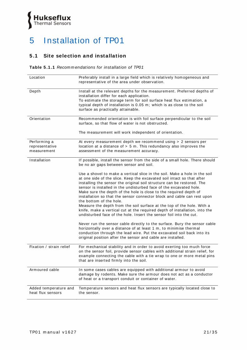
Table 5.1.1 Recommendations for installation of TP01 Location Preferably install in a large field which is relatively homogeneous and
representative of the area under observation.
Depth Install at the relevant depths for the measurement. Preferred depths of installation differ for each application. To estimate the storage term for soil surface heat flux estimation, a typical depth of installation is 0.05 m; which is as close to the soil surface as practically attainable.
Orientation Recommended orientation is with foil surface perpendicular to the soil surface, so that flow of water is not obstructed. The measurement will work independent of orientation.
Performing a representative measurement
At every measurement depth we recommend using > 2 sensors per location at a distance of > 5 m. This redundancy also improves the assessment of the measurement accuracy.
Installation If possible, install the sensor from the side of a small hole. There should be no air gaps between sensor and soil. Use a shovel to make a vertical slice in the soil. Make a hole in the soil at one side of the slice. Keep the excavated soil intact so that after installing the sensor the original soil structure can be restored. The sensor is installed in the undisturbed face of the excavated hole. Make sure the depth of the hole is close to the required depth of installation so that the sensor connector block and cable can rest upon the bottom of the hole. Measure the depth from the soil surface at the top of the hole. With a knife, make a vertical cut at the required depth of installation, into the undisturbed face of the hole. Insert the sensor foil into the cut. Never run the sensor cable directly to the surface. Bury the sensor cable horizontally over a distance of at least 1 m, to minimise thermal conduction through the lead wire. Put the excavated soil back into its original position after the sensor and cable are installed.
Fixation / strain relief
For mechanical stability and in order to avoid exerting too much force on the sensor foil, provide sensor cables with additional strain relief, for example connecting the cable with a tie wrap to one or more metal pins that are inserted firmly into the soil.
Armoured cable In some cases cables are equipped with additional armour to avoid damage by rodents. Make sure the armour does not act as a conductor of heat or a transport conduit or container of water.
Added temperature and heat flux sensors
Temperature sensors and heat flux sensors are typically located close to the sensor.
TP01 manual v1627 22/35
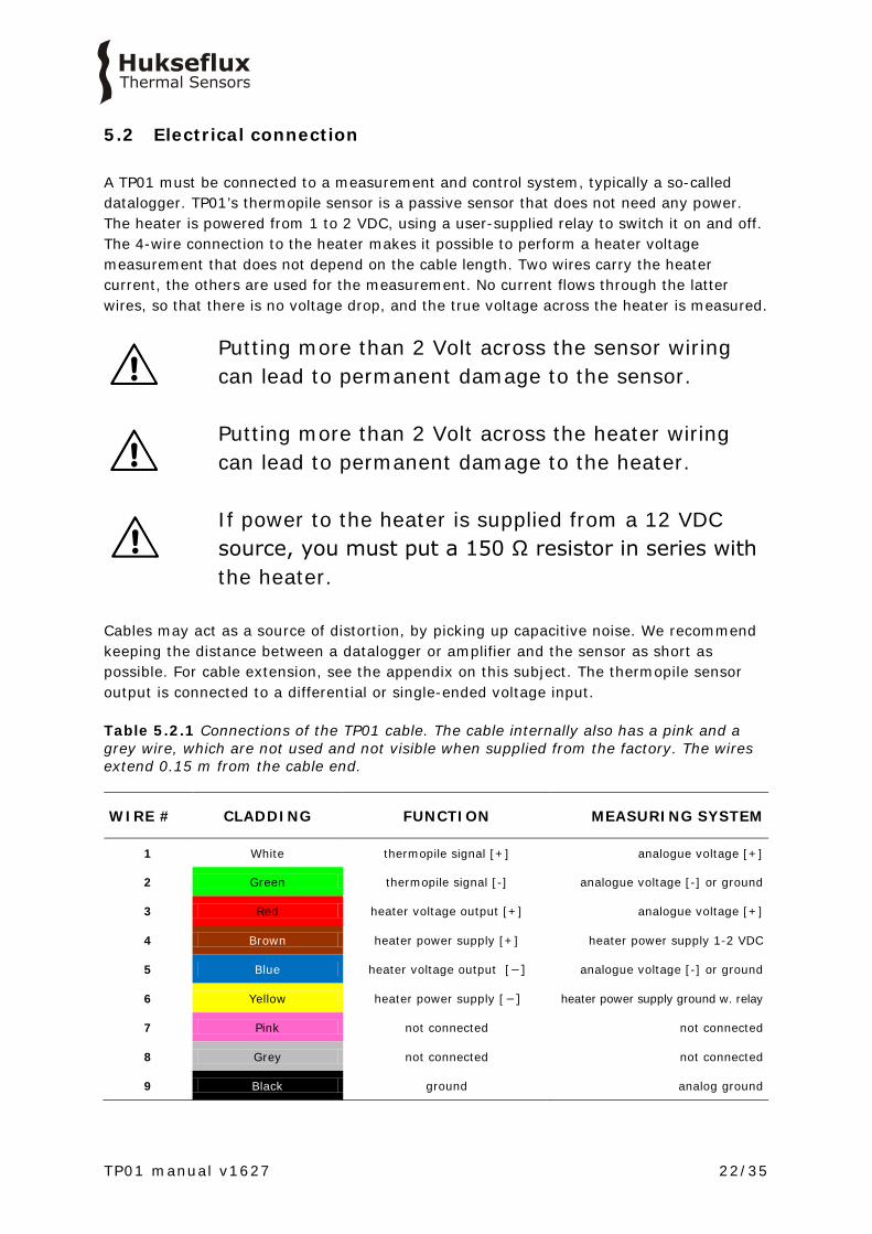
5.2 Electrical connection A TP01 must be connected to a measurement and control system, typically a so-called datalogger. TP01’s thermopile sensor is a passive sensor that does not need any power. The heater is powered from 1 to 2 VDC, using a user-supplied relay to switch it on and off. The 4-wire connection to the heater makes it possible to perform a heater voltage measurement that does not depend on the cable length. Two wires carry the heater current, the others are used for the measurement. No current flows through the latter wires, so that there is no voltage drop, and the true voltage across the heater is measured.
Putting more than 2 Volt across the sensor wiring can lead to permanent damage to the sensor. Putting more than 2 Volt across the heater wiring can lead to permanent damage to the heater. If power to the heater is supplied from a 12 VDC source, you must put a 150 Ω resistor in series with the heater.
Cables may act as a source of distortion, by picking up capacitive noise. We recommend keeping the distance between a datalogger or amplifier and the sensor as short as possible. For cable extension, see the appendix on this subject. The thermopile sensor output is connected to a differential or single-ended voltage input. Table 5.2.1 Connections of the TP01 cable. The cable internally also has a pink and a grey wire, which are not used and not visible when supplied from the factory. The wires extend 0.15 m from the cable end.
WIRE # CLADDING FUNCTION MEASURING SYSTEM
1 White thermopile signal [+] analogue voltage [+]
2 Green thermopile signal [-] analogue voltage [-] or ground
3 Red heater voltage output [+] analogue voltage [+]
4 Brown heater power supply [+] heater power supply 1-2 VDC
5 Blue heater voltage output [−] analogue voltage [-] or ground
6 Yellow heater power supply [−] heater power supply ground w. relay
7 Pink not connected not connected
8 Grey not connected not connected
9 Black ground analog ground

TP01 manual v1627 23/35
Figure 5.2.1 Electrical connection of TP01. Thermopile sensor (2) wires are connected to datalogger inputs 1 and 2. Heater (1) wires are connected to the power supply at 4 and 6 ( with relay). The heater voltage is measured across wires 3 and 5. The relay (not included in the TP01 delivery) is used to switch the heater on and off. Table 5.2.2 Resistance checks for diagnostics of TP01
WIRE # CLADDING CLADDING RESISTANCE ACCEPTANCE
INTERVAL
1-2 White Green 20 to 50 Ω plus 0.1 Ω/m cable resistance
3-4 Red Brown 0.1 Ω/m cable resistance
3-2 Red Green infinite/not connected
3-5 Red Blue 10 to 20 Ω plus 0.1 Ω/m cable resistance
3-6 Red Yellow 10 to 20 Ω plus 0.1 Ω/m cable resistance
3-9 Red Black infinite/not connected
TP01 manual v1627 24/35
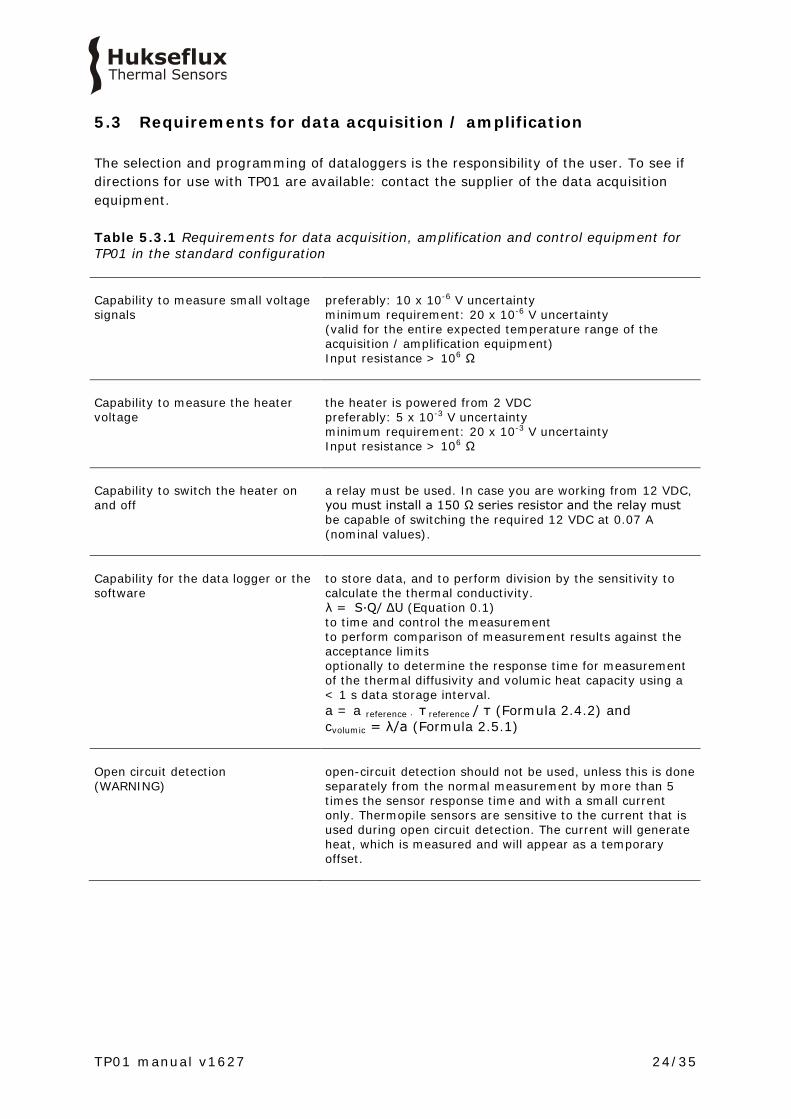
5.3 Requirements for data acquisition / amplification The selection and programming of dataloggers is the responsibility of the user. To see if directions for use with TP01 are available: contact the supplier of the data acquisition equipment. Table 5.3.1 Requirements for data acquisition, amplification and control equipment for TP01 in the standard configuration Capability to measure small voltage signals
preferably: 10 x 10-6 V uncertainty minimum requirement: 20 x 10-6 V uncertainty (valid for the entire expected temperature range of the acquisition / amplification equipment) Input resistance > 106 Ω
Capability to measure the heater voltage
the heater is powered from 2 VDC preferably: 5 x 10⁻³ V uncertainty minimum requirement: 20 x 10-3 V uncertainty Input resistance > 106 Ω
Capability to switch the heater on and off
a relay must be used. In case you are working from 12 VDC, you must install a 150 Ω series resistor and the relay must be capable of switching the required 12 VDC at 0.07 A (nominal values).
Capability for the data logger or the software
to store data, and to perform division by the sensitivity to calculate the thermal conductivity. λ = S·Q/ ΔU (Equation 0.1) to time and control the measurement to perform comparison of measurement results against the acceptance limits optionally to determine the response time for measurement of the thermal diffusivity and volumic heat capacity using a < 1 s data storage interval. a = a reference · τ reference / τ (Formula 2.4.2) and cvolumic = λ/a (Formula 2.5.1)
Open circuit detection (WARNING)
open-circuit detection should not be used, unless this is done separately from the normal measurement by more than 5 times the sensor response time and with a small current only. Thermopile sensors are sensitive to the current that is used during open circuit detection. The current will generate heat, which is measured and will appear as a temporary offset.

TP01 manual v1627 25/35
6 Making a dependable measurement
6.1 Uncertainty evaluation A measurement is called “dependable” if it is reliable, i.e. measuring within required uncertainty limits for most of the time and if problems, once they occur, can be solved quickly. The measurement uncertainty is a function of:
• calibration uncertainty • differences between reference conditions during calibration and measurement
conditions, for example uncertainty caused temperature dependence of the sensitivity • the duration of sensor employment (involving the non-stability) • application errors: the measurement conditions and environment in relation to the
sensor properties, the influence of the sensor on the measurand, the representativeness of the measurement location
• corrections applied It is not possible to give a single estimate for TP01 measurement uncertainty. Statements about the overall measurement uncertainty can only be made on an individual basis, taking all these factors into account.
6.2 Typical measurement uncertainties
Table 6.2.1 Typical measurement uncertainties when measuring with TP01 APPLICATION
TYPICAL MEASUREMENT UNCERTAINTY BUDGET (K=2)
Meteorology
measurements of soil thermal conductivity may attain uncertainties in the order of ± 10 % in the rated measurement range of 0.3 to 5 W/(m·K). measurements of soil thermal diffusivity may attain uncertainties in the ± 20 % range in the rated measurement range of 0.3 to 5 W/(m·K)
TP01 manual v1627 26/35
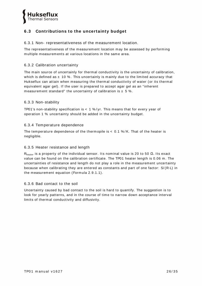
6.3 Contributions to the uncertainty budget
6.3.1 Non- representativeness of the measurement location. The representativeness of the measurement location may be assessed by performing multiple measurements at various locations in the same area.
6.3.2 Calibration uncertainty
The main source of uncertainly for thermal conductivity is the uncertainty of calibration, which is defined as ± 10 %. This uncertainly is mainly due to the limited accuracy that Hukseflux can attain when measuring the thermal conductivity of water (or its thermal equivalent agar gel). If the user is prepared to accept agar gel as an “inherent measurement standard” the uncertainty of calibration is ± 5 %.
6.3.3 Non-stability
TP01’s non-stability specification is < 1 %/yr. This means that for every year of operation 1 % uncertainty should be added in the uncertainty budget.
6.3.4 Temperature dependence The temperature dependence of the thermopile is < 0.1 %/K. That of the heater is negligible.
6.3.5 Heater resistance and length Rheater is a property of the individual sensor. Its nominal value is 20 to 50 Ω. Its exact value can be found on the calibration certificate. The TP01 heater length is 0.06 m. The uncertainties of resistance and length do not play a role in the measurement uncertainty because when calibrating they are entered as constants and part of one factor: S/(R·L) in the measurement equation (Formula 2.9.1.1).
6.3.6 Bad contact to the soil Uncertainty caused by bad contact to the soil is hard to quantify. The suggestion is to look for yearly patterns, and in the course of time to narrow down acceptance interval limits of thermal conductivity and diffusivity.

TP01 manual v1627 27/35
6.3.7 Estimate of the time constant When estimating the thermal diffusivity, the data storage interval must be sufficiently small so that the time constant of the measurement can be compared to the reference time constant of 19 s. Although it is possible to attain good results by curve fitting, the easiest approach is to sample and store date at an interval < 1 s so that the time interval is not the main factor determining the measurement uncertainty.
TP01 manual v1627 28/35
7 Maintenance and trouble shooting
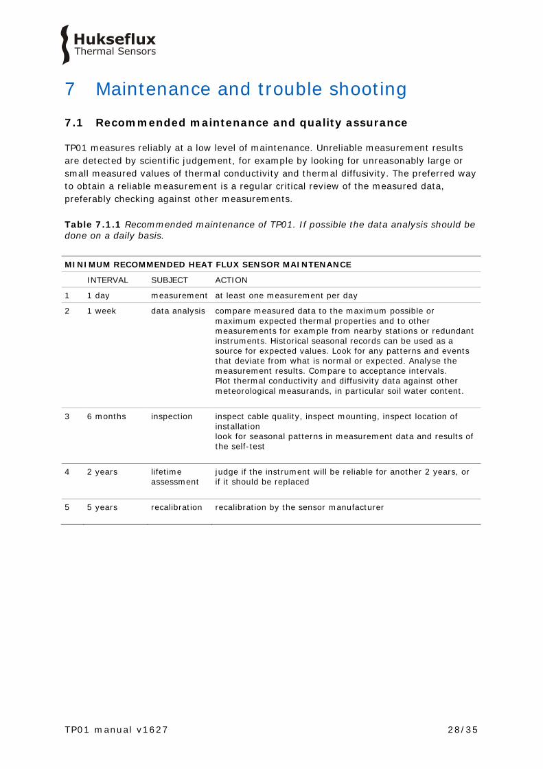
7.1 Recommended maintenance and quality assurance
TP01 measures reliably at a low level of maintenance. Unreliable measurement results are detected by scientific judgement, for example by looking for unreasonably large or small measured values of thermal conductivity and thermal diffusivity. The preferred way to obtain a reliable measurement is a regular critical review of the measured data, preferably checking against other measurements. Table 7.1.1 Recommended maintenance of TP01. If possible the data analysis should be done on a daily basis.
MINIMUM RECOMMENDED HEAT FLUX SENSOR MAINTENANCE
INTERVAL SUBJECT ACTION
1 1 day measurement at least one measurement per day
2 1 week data analysis compare measured data to the maximum possible or maximum expected thermal properties and to other measurements for example from nearby stations or redundant instruments. Historical seasonal records can be used as a source for expected values. Look for any patterns and events that deviate from what is normal or expected. Analyse the measurement results. Compare to acceptance intervals. Plot thermal conductivity and diffusivity data against other meteorological measurands, in particular soil water content.
3 6 months inspection inspect cable quality, inspect mounting, inspect location of installation look for seasonal patterns in measurement data and results of the self-test
4 2 years lifetime assessment
judge if the instrument will be reliable for another 2 years, or if it should be replaced
5 5 years recalibration recalibration by the sensor manufacturer
TP01 manual v1627 29/35
7.2 Trouble shooting
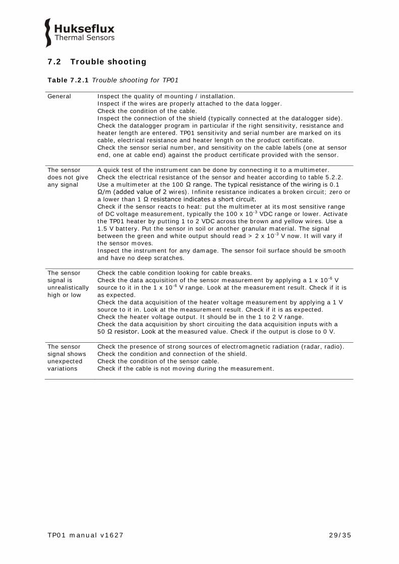
Table 7.2.1 Trouble shooting for TP01 General Inspect the quality of mounting / installation.
Inspect if the wires are properly attached to the data logger. Check the condition of the cable. Inspect the connection of the shield (typically connected at the datalogger side). Check the datalogger program in particular if the right sensitivity, resistance and heater length are entered. TP01 sensitivity and serial number are marked on its cable, electrical resistance and heater length on the product certificate. Check the sensor serial number, and sensitivity on the cable labels (one at sensor end, one at cable end) against the product certificate provided with the sensor.
The sensor does not give any signal
A quick test of the instrument can be done by connecting it to a multimeter. Check the electrical resistance of the sensor and heater according to table 5.2.2. Use a multimeter at the 100 Ω range. The typical resistance of the wiring is 0.1 Ω/m (added value of 2 wires). Infinite resistance indicates a broken circuit; zero or a lower than 1 Ω resistance indicates a short circuit. Check if the sensor reacts to heat: put the multimeter at its most sensitive range of DC voltage measurement, typically the 100 x 10-3 VDC range or lower. Activate the TP01 heater by putting 1 to 2 VDC across the brown and yellow wires. Use a 1.5 V battery. Put the sensor in soil or another granular material. The signal between the green and white output should read > 2 x 10⁻³ V now. It will vary if the sensor moves. Inspect the instrument for any damage. The sensor foil surface should be smooth and have no deep scratches.
The sensor signal is unrealistically high or low
Check the cable condition looking for cable breaks. Check the data acquisition of the sensor measurement by applying a 1 x 10⁻⁶ V source to it in the 1 x 10⁻⁶ V range. Look at the measurement result. Check if it is as expected. Check the data acquisition of the heater voltage measurement by applying a 1 V source to it in. Look at the measurement result. Check if it is as expected. Check the heater voltage output. It should be in the 1 to 2 V range. Check the data acquisition by short circuiting the data acquisition inputs with a 50 Ω resistor. Look at the measured value. Check if the output is close to 0 V.
The sensor signal shows unexpected variations
Check the presence of strong sources of electromagnetic radiation (radar, radio). Check the condition and connection of the shield. Check the condition of the sensor cable. Check if the cable is not moving during the measurement.
TP01 manual v1627 30/35
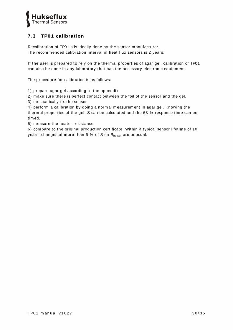
7.3 TP01 calibration
Recalibration of TP01’s is ideally done by the sensor manufacturer. The recommended calibration interval of heat flux sensors is 2 years. If the user is prepared to rely on the thermal properties of agar gel, calibration of TP01 can also be done in any laboratory that has the necessary electronic equipment. The procedure for calibration is as follows: 1) prepare agar gel according to the appendix 2) make sure there is perfect contact between the foil of the sensor and the gel. 3) mechanically fix the sensor 4) perform a calibration by doing a normal measurement in agar gel. Knowing the thermal properties of the gel, S can be calculated and the 63 % response time can be timed. 5) measure the heater resistance 6) compare to the original production certificate. Within a typical sensor lifetime of 10 years, changes of more than 5 % of S en Rheater are unusual.


TP01 manual v1627 32/35
8 Appendices
8.1 Appendix on cable extension / replacement TP01 is equipped with one cable. Keep the distance between data logger or amplifier and sensor as short as possible. Cables may act as a source of distortion by picking up capacitive noise. In an electrically “quiet” environment the TP01 cable may be extended without problem to 100 metres. If done properly, the sensor signal, although small, will not significantly degrade because the sensor resistance is very low (which results in good immunity to external sources) and because there is no current flowing (so no resistive losses). Cable and connection specifications are summarised below. Table 8.1.1 Preferred specifications for cable extension of TP01 Cable
6-wire, shielded, with copper conductor (at Hukseflux 8-wire shielded cable is used, of which only 6 wires are used)
Extension sealing
make sure any connections are sealed against humidity ingress
Conductor resistance
< 0.1 Ω/m
Outer diameter
5 x 10⁻³ m
Length
cables should be kept as short as possible, in any case the total cable length should be less than 100 m
Outer mantle
with specifications for outdoor use (for good stability in outdoor applications)
Connection
either solder the new cable conductors and shield to those of the original sensor cable, and make a waterproof connection using heat-shrink tubing with hot-melt adhesive, or use gold plated waterproof connectors. Always connect the shield
8.2 Appendix on preparation of agar gel for calibration
The procedure for calibration of TP01 relies on the use of agar gel. This is a water-based gel, of which the ingredients can be bought in every pharmacy. In most countries agar is also available in food stores that sell environmentally friendly foods. The agar gel is often used for growing bacteria. The agar itself does not significantly influence the thermal properties of water, but reduces the effects of convection.

TP01 manual v1627 33/35
Prepare agar gel by cooking about 4 grams of agar in 1 litre of water, for about 20 minutes, stirring regularly. The solution is put in a pot, and be allowed to cool down and solidify. This typically takes some hours. Use a pot which may be sealed. Once at room temperature, make a slit in the gel using a knife. Insert the TP01 into the slit. Add some water with a liquid antiseptic such as Dettol to suppress bacterial growth, and promote the thermal contact between the gel and the sensor foil. Make sure the water fully covers the gel in a layer of about 1 x 10⁻³ m. We assume by scientific judgement that the properties of agar gel at 4 x 10⁻³ kg/kg are the same as those of pure water: Thermal conductivity: 0.6 W/(m·K), at 20 °C Thermal diffusivity: 0.14 10-6 m2 /s
8.3 Appendix on use of TP01 beyond its rated measurement range
The rated measurement range of TP01 is 0.3 to 5 W/(m·K). Use beyond this rated range is possible, but will lead to higher measurement uncertainties. At lower thermal conductivities the thermal transport through the thermopile metal traces leads to non-linear behaviour. At higher thermal conductivities, the output signal reduces. Table 8.3.1 lists some measurement results. Table 8.3.1 Measurements results with TP01 using the normal measurement equation. Dry sand (zero moisture content, which will not occur in a real-life situation) and air are beyond the rated measurement range. The sensor behaviour is strongly non-linear. A measurement in agar gel is at calibration reference conditions and by definition has zero deviation.
air
dry
sand
moist sand
agar gel
saturated sand
theoretical [W/(m·K)] 0.02 0.19 0.30 0.61 2.22
measured [W/(m·K)] 0.16 0.29 0.32 0.61 2.11
deviation from ideal
[%] 689 53 8 0 -5

TP01 manual v1627 34/35
8.4 EU declaration of conformity
We, Hukseflux Thermal Sensors B.V. Delftechpark 31 2628 XJ Delft The Netherlands in accordance with the requirements of the following directive: 2014/30/EU The Electromagnetic Compatibility Directive hereby declare under our sole responsibility that: Product model: TP01 Product type: Thermal properties sensor has been designed to comply and is in conformity with the relevant sections and applicable requirements of the following standards: Emission: EN 61326-1 (2006) Immunity: EN 61326-1 (2006) Emission: EN 61000-3-2 (2006) Emission: EN 61000-3-3 (1995) + A1 (2001) + A2 (2005) Report: 08C01340RPT01, 06 January 2009
Eric HOEKSEMA Director Delft September 08, 2015

© 2016, Hukseflux Thermal Sensors B.V. www.hukseflux.com
Hukseflux Thermal Sensors B.V. reserves the right to change specifications without notice.