user manual - mediacdn.eu · ssa3000x user manual 3 ... 3. tg when the tg function ... letter in...
TRANSCRIPT

User Manual
SSA3000X Series Spectrum Analyzer
UM0703X-E01A
2015 SIGLENT TECHNOLOGIES CO., LTD.

SIGLENT
SSA3000X User Manual I
Copyright Information
SIGLENT TECHNOLOGIES CO., LTD. All Rights Reserved.
Information in this publication replaces all previously corresponding material.
SIGLENT reserves the right to modify or change parts of or all the specifications or pricing
policies at company’s sole decision.
Any way of copying, extracting or translating the contents of this manual is not allowed
without the permission of SIGLENT.
Note: SIGLENT is the registered trademark of SIGLENT TECHNOLOGIES CO., LTD.
SIGLENT
II SSA3000X User Manual
General Safety Summary
Carefully read the following safety precautions to avoid any personal injury or damage to
the instrument and any products connected to it. To avoid potential hazards, please use the
instrument as specified.
Use Proper AC Power Line
Only the power cord designed for the instrument and authorized by local country should be
used.
Ground the Instrument
The instrument is grounded through the protective earth conductor of the power line. To
avoid electric shock, please make sure the instrument is grounded correctly before
connecting its input or output terminals.
Connect the Probe Correctly.
If a probe is used, do not connect the ground lead to high voltage since it has isobaric
electric potential as the ground.
Look Over All Terminals’ Ratings
To avoid fire or electric shock, please look over all ratings and sign instruction of the
instrument. Before connecting the instrument, please read the manual carefully to gain
more information about the ratings.
Use Proper Overvoltage Protection
Make sure that no overvoltage (such as that caused by a thunderstorm) can reach the
product, or else the operator might be exposed to danger of electrical shock.
Electrostatic Prevention
Operate the instrument in an electrostatic discharge protective area environment to avoid
damages induced by static discharge. Always ground both the internal and external
conductors of the cable to release static before connecting.
Maintain Proper Ventilation
Inadequate ventilation may cause increasing of the instrument’s temperature, which will
eventually damage the instrument. So keep well ventilated and inspect the intake and fan
regularly.
Avoid Exposed Circuit or Components
Do not touch exposed contacts or components when the power is on.
Do Not Operate Without Covers
Do not operate the instrument with covers or panels removed.
Use Only the Specified Fuse.
Keep Product Surfaces Clean and Dry.
To avoid the influence of dust and/or moisture in the air, please keep the surface of the
device clean and dry.
Do Not Operate in Wet Conditions.
In order to avoid short circuiting to the interior of the device or electric shock, please do not
operate the instrument in a humid environment.
Do Not Operate in an Explosive Atmosphere.
In order to avoid damage to the device or personal injury, it is important to operate the
device away from an explosive atmosphere.

SIGLENT
SSA3000X User Manual III
Safety Terms and Symbols
Terms on the product. These terms may appear on the product:
DANGER Indicates direct injuries or hazards that may happen.
WARNING Indicates potential injuries or hazards that may happen.
CAUTION Indicates potential damages to the instrument or other property that may
happen.
Symbols on the product. These symbols may appear on the product:
Hazardous Protective Warning Earth Chassis
Voltage Ground Ground
SIGLENT
IV SSA3000X User Manual
SSA3000X Series Spectrum Analyzer Overview
SSA3000X series spectrum analyzer has a frequency range from 9 kHz up to 2.1 GHz/3.2
GHz, it is light weight and small size, with an user friendly interface, concise style of display,
reliable measurement precision and plenty of RF measurement functions. Applicable to
research and development, education, production, maintenance and other related fields,
that meets a wider range of application requirements.
Features and Benefits
All-Digital IF Technology
Frequency Range from 9 kHz up to 3.2 GHz
-161 dBm/Hz Displayed Average Noise Level (Typ.)
-98 dBc/Hz @10 kHz Offset Phase Noise (1 GHz, Typ.)
Total Amplitude Accuracy < 0.7 dB
10 Hz Minimum Resolution Bandwidth(RBW)
Standard Preamplifier
Up to 3.2 GHz Tracking Generator Kit (Opt.)
Reflection Measurement Kit (Opt.)
Advanced Measurement Kit (Opt.)
EMI Pre-compliance Measurements Kit (Opt.)
10.1 inch WVGA(1024x600)Display

SIGLENT
SSA3000X User Manual V
Contents
SSA3000X Series Spectrum Analyzer ..................................................................................... I
Copyright Information ............................................................................................................... I
General Safety Summary ........................................................................................................ II
Safety Terms and Symbols .................................................................................................... III
SSA3000X Series Spectrum Analyzer Overview ................................................................... IV
Chapter 1 Quick Start ......................................................................................................... 1
1.1 Appearance and Dimension .................................................................................. 2
1.2 To Prepare for Use ................................................................................................ 3
1.2.1 Adjust the Supporting Legs ........................................................................ 3
1.2.2 Connect to AC Power Supply ..................................................................... 4
1.3 The Front Panel .................................................................................................... 5
1.3.1 Front Panel Function Keys ......................................................................... 6
1.3.2 Front Panel Key Backlight .......................................................................... 7
1.3.3 To Use the Numeric Keyboard .................................................................... 7
1.3.4 Front Panel Connectors .............................................................................. 9
1.4 Rear Panel ........................................................................................................... 11
1.5 User Interface ...................................................................................................... 12
1.6 Menu Operation .................................................................................................. 14
1.7 Parameter Setting ............................................................................................... 15
1.8 To Use the Built-in Help ....................................................................................... 16
1.9 To Use the Security Lock ..................................................................................... 17
Chapter 2 Front Panel Operation ..................................................................................... 18
2.1 Basic Settings ..................................................................................................... 19
2.1.1 Frequency ................................................................................................ 19
2.1.2 Span ......................................................................................................... 23
2.1.3 Amplitude ................................................................................................. 24
2.1.4 Auto Tune ................................................................................................. 28
2.2 Sweep and Function Settings .............................................................................. 30
2.2.1 BW ............................................................................................................ 30
2.2.2 Trace ........................................................................................................ 31
2.2.3 Detect ....................................................................................................... 34
2.2.4 Sweep ...................................................................................................... 34
2.2.5 Trigger ...................................................................................................... 36
2.2.6 Limit .......................................................................................................... 37
2.2.7 TG ............................................................................................................ 38
2.2.8 Demod ...................................................................................................... 40
2.3 Marker Setup ....................................................................................................... 42
2.3.1 Marker ...................................................................................................... 42
2.3.2 Marker -> .................................................................................................. 45
2.3.3 Marker Fn ................................................................................................. 47
2.3.4 Peak ......................................................................................................... 49

SIGLENT
VI SSA3000X User Manual
2.4 Measurement ...................................................................................................... 52
2.4.1 Meas ......................................................................................................... 52
2.4.2 Meas setup ............................................................................................... 52
2.5 System ................................................................................................................ 59
2.5.1 System ..................................................................................................... 59
2.5.2 Display ...................................................................................................... 60
2.5.3 File ............................................................................................................ 61
2.6 Shortcut Key ........................................................................................................ 63
2.6.1 Preset ....................................................................................................... 63
2.6.2 Couple ...................................................................................................... 66
2.6.3 Help .......................................................................................................... 66
2.6.4 Save ......................................................................................................... 66
Chapter 3 General Inspection and Troubleshooting ......................................................... 67
3.1 General Inspection .............................................................................................. 67
3.2 Troubleshooting ................................................................................................... 68
Chapter 4 Service and Support ........................................................................................ 70
4.1 Maintain Summary .............................................................................................. 70
4.2 Contact Us .......................................................................................................... 70

SIGLENT
SSA3000X User Manual I
Chapter 1 Quick Start This chapter guides users to quickly get familiar with the appearance, dimensions, front/ rear panel
and the user interface, as well as announcements during first use of SSA3000X series spectrum
analyzer.
Subjects in this chapter:
Appearance and Dimension
To Prepare for Use
The Front Panel
Rear Panel
User Interface
Menu Operation
Parameter Setting
To Use the Built-in Help
To Use the Security Lock
SIGLENT
2 SSA3000X User Manual
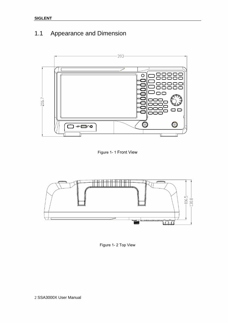
1.1 Appearance and Dimension
Figure 1- 1 Front View
Figure 1- 2 Top View

SIGLENT
SSA3000X User Manual 3
1.2 To Prepare for Use
1.2.1 Adjust the Supporting Legs
Adjust the supporting legs properly to use them as stands to tilt the Spectrum Analyzer upwards for
stable placement as well as easier operation and observation of the instrument.
Figure 1- 3 Before adjusting Figure 1- 4 After adjusting
SIGLENT
4 SSA3000X User Manual
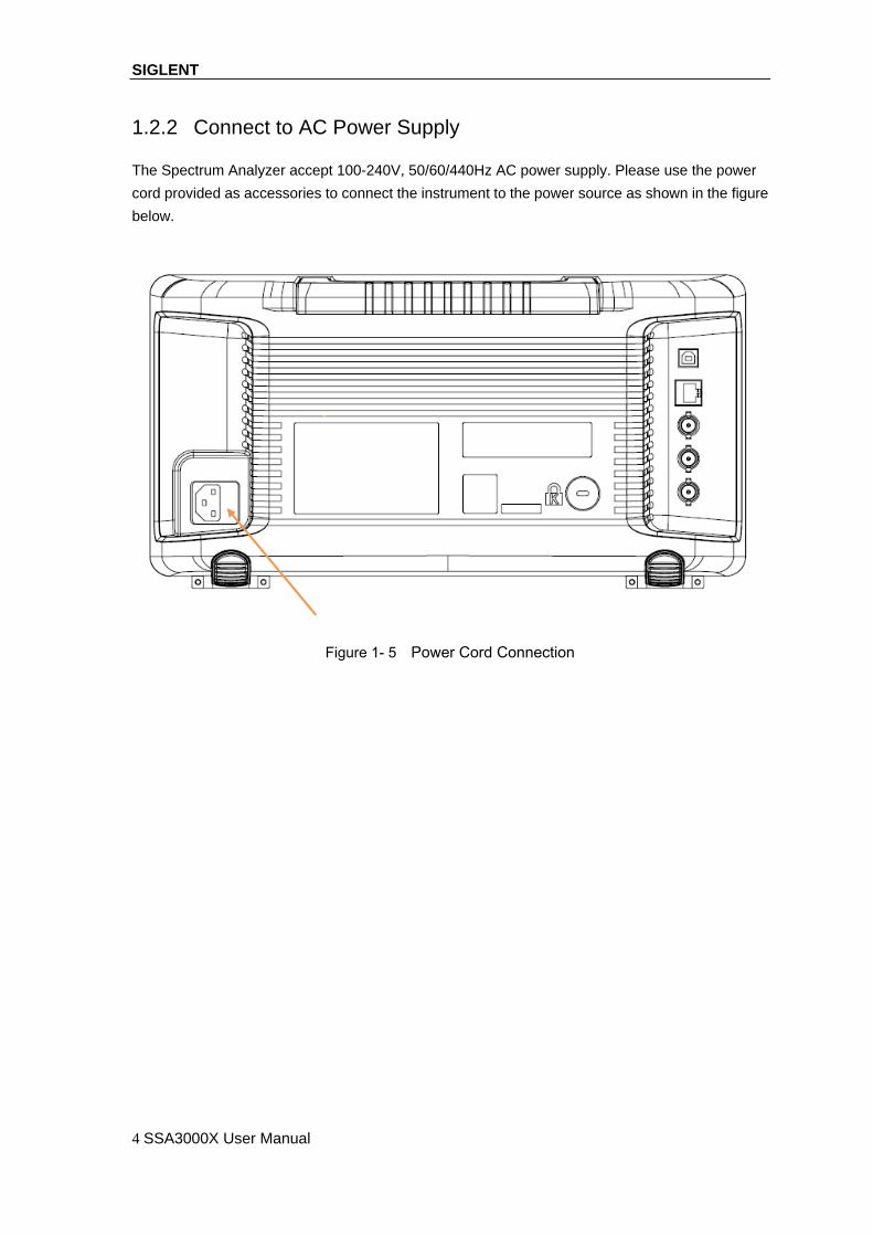
1.2.2 Connect to AC Power Supply
The Spectrum Analyzer accept 100-240V, 50/60/440Hz AC power supply. Please use the power
cord provided as accessories to connect the instrument to the power source as shown in the figure
below.
Figure 1- 5 Power Cord Connection

SIGLENT
SSA3000X User Manual 5
1.3 The Front Panel
Figure 1- 6 The Front Panel
Table 1- 1 Front Panel Description
NO. Description NO. Description
1 User Graphical Interface 2 Menu Control Keys
3 Function Keys 4 Knob
5 Arrow Keys 6 RF Input
7 Numeric Keyboard 8 TG Output
9 Earphone interface 10 USB Host
11 Power Switch

SIGLENT
6 SSA3000X User Manual
1.3.1 Front Panel Function Keys
Figure 1- 7 Function Keys area
Table 1- 2 Function keys description
Function keys Description
Frequency Sets the Center Freq\Start Freq\Stop Freq\Freq Step
Span Sets the Span\Full Span\Zero Span\Zoom In\Zoom Out\Last Span
Amplitude Used to Set the REF Level\Attenuator\Preamp\Amplitude
Auto Tune Automatically sets the optimal parameters according to the characteristics of
the signal
BW Used to adjust the RBW,VBW,VBW/RBW Rate, Average Type
(Logpower\Power\Voltage)
Trace Selects Trace\Trace setup\Trace math
Sweep Selects the Sweep time\Sweep Rule\Sweep Mode
Detect Selects the Detector type
Trigger Used in Selecting the Free Trigger\Video Trigger/ External Trigger
Limit Sets the Pass\Fail Limit
TG Sets the TG Level\TG Level offset\Normalize
Demod Used to set the Parameters of the AM and FM
Marker Used to Select the Mark Trace and Marker math
Marker-> Sets all types of Markers to Freq
Marker Fn Selects the Noise Marker\N dB BW\Freq Counter\Read out of Freq
Peak Searches for the Peak Signal and Counts the Peak Frequency
Meas Selects the Channel Power\ACPR\Occupied BW\T-Power
Meas Setup Used to Choose the Parameters Details of Channel Power\ACPR

SIGLENT
SSA3000X User Manual 7
\Occupied BW\T-Power
System Selects the Language\Power on/Preset\Interface\Calibration\
system information\Data&Time\Self Test
Mode Selects the Spec Analyzer\EMI\Reflection Meas
Display Used to Adjust the Grid Brightness\Display Line
File Use to Select the File system
Preset Sets the system to default status
Couple Used to Select the RBW\VBW\Attenuator\Freq Step\Sweep time mode
Help Help Information Switch
Save Save Shortcut Key
1.3.2 Front Panel Key Backlight
The on/off state and the color of the backlights of some keys at the front panel indicate the working
state of the spectrum analyzer. The states are as listed below.
1. Power Switch
Flash on and off alternatively, in breathing state: indicate the unit is in stand-by state.
Constant on: indicate the instrument is in normal operating state.
2. Mode
When the EMI or Reflection Meas function is enabled, the backlight of Mode turns on .
When the function is Spec Analyzer, the backlight is turn off.
3. TG
When the TG function is enabled, the backlight of TG turns on and turns off when the function
is disabled.
1.3.3 To Use the Numeric Keyboard
SSA3000X provides a numeric keyboard at the front panel (as shown in the figure below). The
numeric keyboard which supports the Chinese characters, English uppercase/lowercase
characters, numbers and common symbols (including decimal point, #, space and +/-) are mainly
used to edit file or folder name and set parameters (refer to “Parameter Setting”).

SIGLENT
8 SSA3000X User Manual
Figure 1- 8 Numeric Keyboard
1.
Press this key can change the Number and letter during file or folder name editing.
2.
Multiplexing keys for numbers and letters. They are used to directly input the desired
number or letter.
press this key to input 1 in number input and switch between uppercase and lowercase
letter in English input.
3.
Press this key to input a decimal point in number input.
Press this key to input special character in English input.
4.Back
During the process of parameter editing, press this key to delete the character on the left of
the cursor.
5. Esc
During parameter editing process, press this key to clear the inputs in the active function
area and exit parameter input.
When the instrument is in remote mode, use this key to return to local mode.
6.Enter
When pressed during parameter editing process, the system will complete the input and insert
a default unit for the parameter automatically.

SIGLENT
SSA3000X User Manual 9
1.3.4 Front Panel Connectors
Figure 1- 9 Front Panel Connectors
1. Power Switch
Power up/Power down the instrument
2. USB Host
The analyzer can serve as a “host” device to connect external USB devices. This interface
is available for USB storage devices.
Read the trace or state file stored in the USB storage device, store the current instrument
state or trace in the USB storage device or store the contents currently displayed on the
screen in the USB storage device in “.bmp” format.
3. Earphone Jack
The analyzer provides AM and FM demodulations. Insert the earphone to the jack to aquire
the audio output of the demodulated signal. You can turn on or off the earphone output and
adjust the volume via Demod ->Volume.

SIGLENT
10 SSA3000X User Manual
CAUTION
For fear of damaging your hearing, please turn the volume down to zero
and gradually turn the volume up after putting on the earphone.
4.TG OUTPUT
The output of the tracking generator can be connected to a receiver through a
cable with an N male connector.
CAUTION
To avoid damage to the tracking generator, the reverse DC voltage cannot
exceed 50 V
5.RF INPUT
CAUTION
To avoid damage to the instrument, for the signal input from the RF input
terminal, the DC voltage component and the maximum continuous power
of the AC (RF) signal component can not exceed 50 V and +30 dBm
respectively.

SIGLENT
SSA3000X User Manual 11
1.4 Rear Panel
Figure 1- 10 Rear Panel
1、 Handle
Pull up the handle vertically for easy carrying of the instrument. When you do not need the
handle, press it down.
2、USB Device interface
The analyzer can serve as a “slave” device to connect external USB devices. Through this
interface, a PC can be connected to control SSA3000X remotely through programming or PC
software.
3、 LAN interface
Through this interface, the analyzer can be connected to your local network for remote control.
4、 REF IN 10MHz
SSA3000X can use internal or external reference source.
When a 10 MHz external clock signal is received through the [10MHz IN] connector, this
signal is used as the external reference source and “Ext Ref” is displayed in the status
bar of the user interface. When the external reference is lost, transfinite or not connected, the
instrument switches to its internal reference source automatically and “Ext Ref” on the screen
disappears.
The [10MHz IN] and [10MHz OUT] connectors are usually used to build synchronization
among multiple instruments.

SIGLENT
12 SSA3000X User Manual
5、REF OUT 10MHz
SSA3000X can use internal or external reference source.
When internal reference source is used, the [10MHz OUT] connector can output a 10 MHz
clock signal generated by the analyzer. This signal can be used to synchronize other
instruments.
The [10MHz OUT] and [10MHz IN] connectors are usually used to build synchronization
among multiple instruments.
6、Trigger in
In external trigger mode, the connector receives an external trigger signal through a BNC
cable.
7、Security Lock Hole
If needed, you can use a security lock (buy it yourself) to lock the analyzer to a desired
location.
8、Connect to AC Power Supply
The Spectrum Analyzer accept 100-240V, 50/60/440Hz AC power supply. Please use the
power cord provided as accessories to connect the instrument
1.5 User Interface
Figure 1- 11 User Interface
Table 1- 3 User Interface labels

SIGLENT
SSA3000X User Manual 13
NO. Name Description
1 SIGLENT Logo of SIGLENT
2 Ref Reference level
3 UNCAL When the sweep time less than the auto couple time,
the measure result may be inaccuracy, at the same
time appear the “UNCAL”
4 Active function area Current parameter and its value
5 EXT REF Ext Ref
6 Att ATT Value
7 Day and time System time
8、9、11 Cursor parameter 8:Current active cursor; 9:current cursor frequency
value 11:current cursor amplitude value;
10 Auto Tune Automatically sets the optimal parameters according to
the characteristics of the signal
12 USB storage device
identification
The identification is displayed when
13 Menu title Function of the current menu.
14 Menu items Menu items of the current function
15 Operation status Local is local mode,RMT is remote mode
16 Sweep time Sweep time
17 Span or stop
Frequency
The frequency range of the current sweep channel can
be expressed by the combination of center frequency
and span or the combination of start frequency and
stop frequency
18 Sweep progress bar Sweep progress bar
19 Pass/Fail status Pass/Fail status
20 VBW Video bandwidth
21 Spectrum trace Spectrum trace
22 RBW Resolution bandwidth
23 Center or start
frequency
The frequency range of the current sweep channel can
be expressed by the combination of center frequency
or the combination of start frequency
24、25、
26、27
Trace status Can set the trace A\B\C\D is Clear Write\Max Hold\Min
Hold\Freeze\Average times\Math
28 AM or FM AM or FM identification
29 PA Enable or disable Preamplifier
30 FFT Sweep mode is FFT
31 Single or Continue Sweep mode single or continue
32 Average type Log power\Power\Voltage power
33 Trigger type Free\Video\External trigger
34、35 Ref offset 34:Ref offset identification;35:Ref offset value
36 Scale/Div Scale value
37 Scale type Logarithm or linearity

SIGLENT
14 SSA3000X User Manual
1.6 Menu Operation
There are 7 types of menus according to their operation modes. Each type of menu and its
operation method are introduced below.
1、Parameter Input
When selected, use the numeric keys to modify the parameters
directly.
For example, select Center Freq, input the desired figure and press
Enter to change the center frequency.
2、state switching
Press the corresponding menu key to switch between the
sub-options.
For example, press Preamp to enable or disable the signal tracking
function.
3、 Enter Lower Menu(with parameter)
Press the corresponding menu key to enter the lower menu and
change the option currently selected. The parameter in the upper menu
will change when you return to the upper menu.
For example, press Units to enter the lower menu. Select dBm and
return to the previous menu. The unit of Y-axis changes to dBm.
4、Enter Lower Menu (without parameter)
Press the corresponding menu key to enter the lower menu.
For example, press Calibration to enter the lower menu directly.
5、Direct Execution
Press the key to execute the corresponding function.
For example, press Peak->CF to execute a peak search and set the
center frequency of the analyzer to the frequency of the current peak
signal.
6、Function Switch + Parameter Input
Press the corresponding menu key to switch between functions;
change the parameter directly using the numeric keys.
For example, press CF Step to switch between Auto and Manual; if
Manual is selected, you can directly input the desired number to
change the CF Step.
7、State Selection
Press the corresponding menu key to modify the parameter and
return to the menu one level up.
For example, press Trig Type -> Free Run to select free trigger and
the analyzer is in Free Run state at present.

SIGLENT
SSA3000X User Manual 15
1.7 Parameter Setting
Users can enter the desired parameter values using the numeric keys, knob or Arrow keys. This
section describes the three methods of parameter setting through an example (to set the center
frequency to 100 MHz).
1. Use the numeric keyboard
1) Press Frequency->”Center Freq”
2) Input 100 using the numeric keys;
3) Select the desired unit (MHz) from the popup menu.
2. Use the knob
When the parameter is editable (namely when the parameter is selected), turn the knob clockwise
to increase or counterclockwise to decrease the parameter value at the specified step.
1) Press Frequency->”Center Freq”
2) Rotate the knob until the parameter is set to the desired value (100 MHz).
Figure 1- 12 Knob
Note: In the storage function, the knob can also be used to select the current path or file.
3. Use the arrow keys
When the parameter is editable (namely when the parameter is selected), you can increase or
decrease the parameter value at the specific step using the direction keys.
1) press Frequency ->”Center Freq”
2) Press the up/down Arrow key until the parameter is set to the desired value (100 MHz).

SIGLENT
16 SSA3000X User Manual
1.8 To Use the Built-in Help
The built-in help system provides information about every function key at the front panel and every
menu soft key.
1. How to acquire built-in help
Press Help and a prompt about how to obtain help information will be shown at the center of the
screen. Then, press the key that you want to get help of and the relevant help information will be
shown at the center of the screen.
2. Close the current help information
When the help information show at the center of the screen. Press the Help button, It will close
the help information.
Figure 1- 13 help information
SIGLENT
SSA3000X User Manual 17
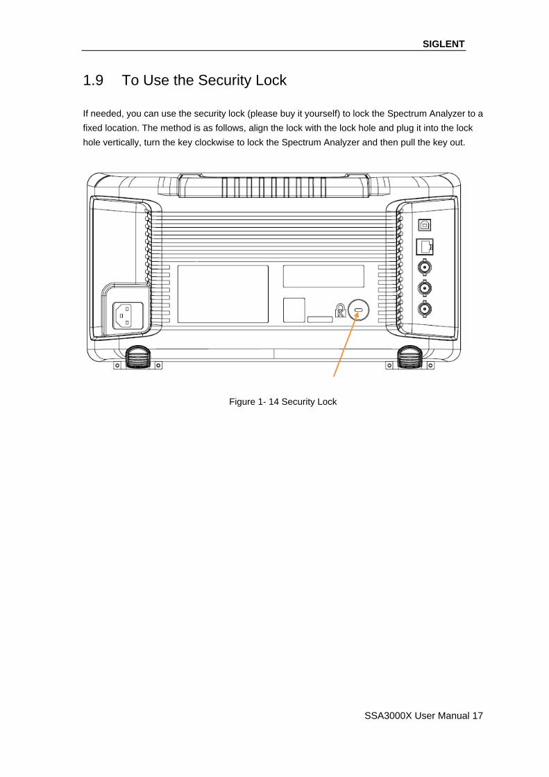
1.9 To Use the Security Lock
If needed, you can use the security lock (please buy it yourself) to lock the Spectrum Analyzer to a
fixed location. The method is as follows, align the lock with the lock hole and plug it into the lock
hole vertically, turn the key clockwise to lock the Spectrum Analyzer and then pull the key out.
Figure 1- 14 Security Lock

SIGLENT
18 SSA3000X User Manual
Chapter 2 Front Panel Operation
This chapter describes in detail the function keys at the front panel and the associated functions.
Subjects in this chapter:
Basic Settings
Sweep and Function Settings
Marker Setup
Measurement
System
Shortcut Key
SIGLENT
SSA3000X User Manual 19
2.1 Basic Settings
2.1.1 Frequency
Set the frequency parameters and functions of the analyzer. Restarts sweeping every time the
frequency parameters are modified.
The frequency range of a channel can be expressed by either of three groups of parameters: Start
Frequency, Center Frequency and Stop Frequency. If any of the parameters is changed, The
others would be adjusted automatically in order to ensure the coupling relationship among them
startstopspan
stopstartcenter
fff
)/2f(ff
The spanf is span
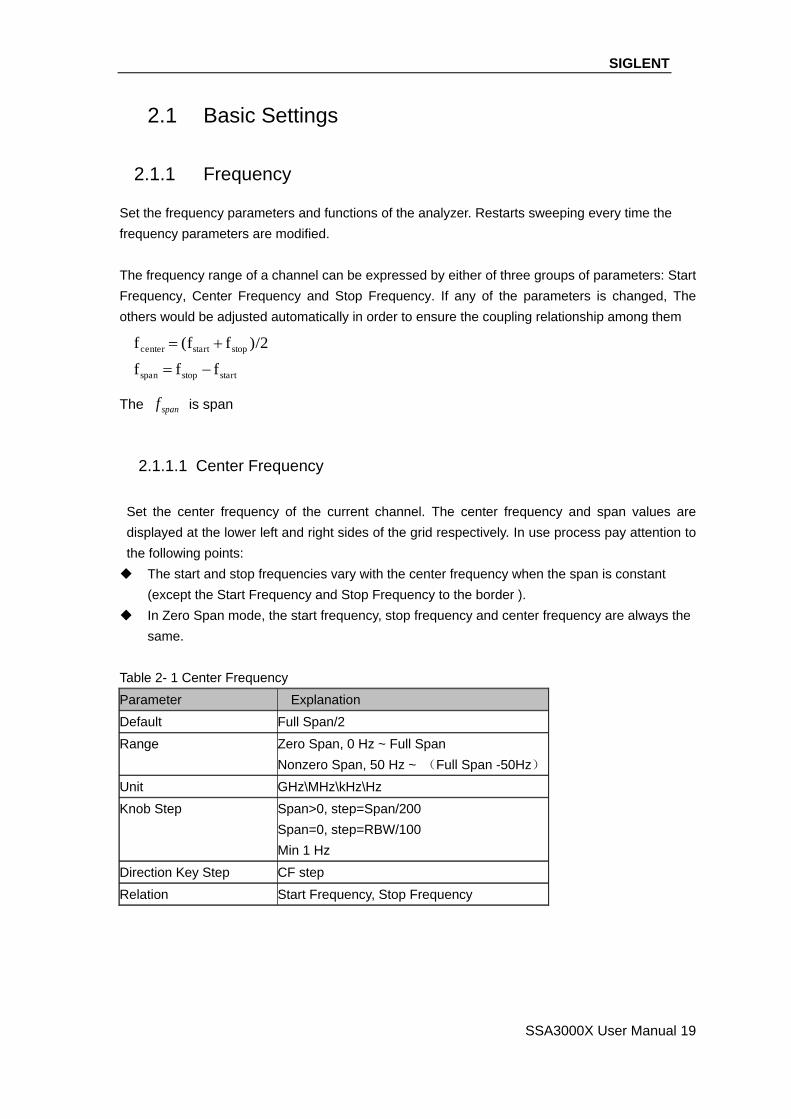
2.1.1.1 Center Frequency
Set the center frequency of the current channel. The center frequency and span values are
displayed at the lower left and right sides of the grid respectively. In use process pay attention to
the following points:
The start and stop frequencies vary with the center frequency when the span is constant
(except the Start Frequency and Stop Frequency to the border ).
In Zero Span mode, the start frequency, stop frequency and center frequency are always the
same.
Table 2- 1 Center Frequency
Parameter Explanation
Default Full Span/2
Range Zero Span, 0 Hz ~ Full Span
Nonzero Span, 50 Hz ~ (Full Span -50Hz)
Unit GHz\MHz\kHz\Hz
Knob Step Span>0, step=Span/200
Span=0, step=RBW/100
Min 1 Hz
Direction Key Step CF step
Relation Start Frequency, Stop Frequency
SIGLENT
20 SSA3000X User Manual
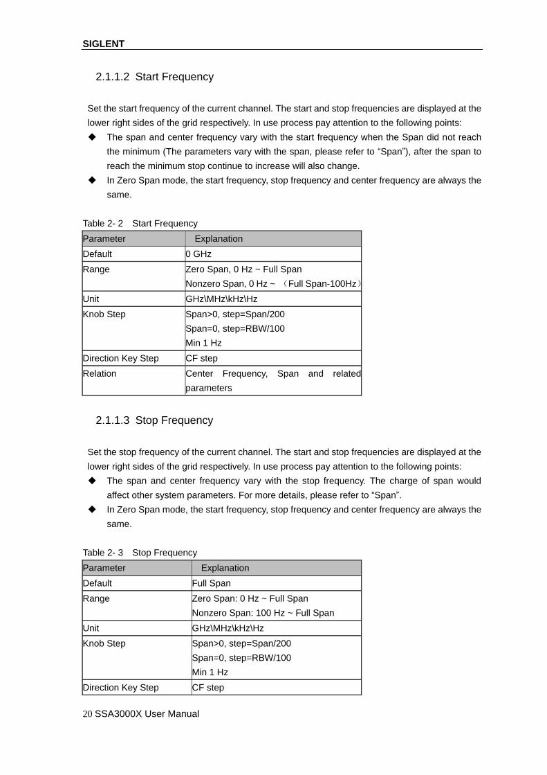
2.1.1.2 Start Frequency
Set the start frequency of the current channel. The start and stop frequencies are displayed at the
lower right sides of the grid respectively. In use process pay attention to the following points:
The span and center frequency vary with the start frequency when the Span did not reach
the minimum (The parameters vary with the span, please refer to “Span”), after the span to
reach the minimum stop continue to increase will also change.
In Zero Span mode, the start frequency, stop frequency and center frequency are always the
same.
Table 2- 2 Start Frequency
Parameter Explanation
Default 0 GHz
Range Zero Span, 0 Hz ~ Full Span
Nonzero Span, 0 Hz ~ (Full Span-100Hz)
Unit GHz\MHz\kHz\Hz
Knob Step Span>0, step=Span/200
Span=0, step=RBW/100
Min 1 Hz
Direction Key Step CF step
Relation Center Frequency, Span and related
parameters
2.1.1.3 Stop Frequency
Set the stop frequency of the current channel. The start and stop frequencies are displayed at the
lower right sides of the grid respectively. In use process pay attention to the following points:
The span and center frequency vary with the stop frequency. The charge of span would
affect other system parameters. For more details, please refer to “Span”.
In Zero Span mode, the start frequency, stop frequency and center frequency are always the
same.
Table 2- 3 Stop Frequency
Parameter Explanation
Default Full Span
Range Zero Span: 0 Hz ~ Full Span
Nonzero Span: 100 Hz ~ Full Span
Unit GHz\MHz\kHz\Hz
Knob Step Span>0, step=Span/200
Span=0, step=RBW/100
Min 1 Hz
Direction Key Step CF step

SIGLENT
SSA3000X User Manual 21
Relation Center Frequency, Span and related
parameters
2.1.1.4 Freq Step
Arrow key step of the center frequency. start frequency and stop frequency vary with the stop
frequency. In use process pay attention to the following points:
At a fixed step change the value of the center frequency can reach the purpose of
continuous measurement channel switch.
There are two kinds of frequency step mode:Auto and manual. In Auto mode, the CF step
is 1/10 of the span in Non-zero span mode or equals the RBW while in Zero span mode; in
Manual mode; you can set the step using the numeric keys.
Table 2- 4 Frequency step
Parameter Explanation
Default Full Span/10
Range 1Hz ~ Full Span
Unit GHz、MHz、kHz、Hz
Knob Step Span>0,Step=Span/200
Span=0,Step=100
min 1 Hz
Direction Key Step 1-2-5 sequence step
Relation RBW, Span and related parameters
2.1.1.5 Peak -> CF
Execute a peak search and use the frequency of the current peak as the center frequency (CF) of
the analyzer. The function is invalid in Zero Span mode.

SIGLENT
22 SSA3000X User Manual
Figure 2- 1 Before Peak -> CF
Figure 2- 2 After peak -> CF
SIGLENT
SSA3000X User Manual 23
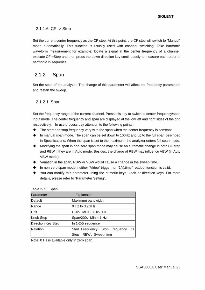
2.1.1.6 CF -> Step
Set the current center frequency as the CF step. At this point, the CF step will switch to “Manual”
mode automatically. This function is usually used with channel switching. Take harmonic
waveform measurement for example: locate a signal at the center frequency of a channel,
execute CF->Step and then press the down direction key continuously to measure each order of
harmonic in sequence
2.1.2 Span
Set the span of the analyzer. The change of this parameter will affect the frequency parameters
and restart the sweep.
2.1.2.1 Span
Set the frequency range of the current channel. Press this key to switch to center frequency/span
input mode .The center frequency and span are displayed at the low left and right sides of the grid
respectively. In use process pay attention to the following points:
The start and stop frequency vary with the span when the center frequency is constant.
In manual span mode. The span can be set down to 100Hz and up to the full span described
in Specifications. When the span is set to the maximum, the analyzer enters full span mode.
Modifying the span in non-zero span mode may cause an automatic change in both CF step
and RBW if they are in Auto mode. Besides, the charge of RBW may influence VBW (in Auto
VBW mode).
Variation in the span, RBW or VBW would cause a change in the sweep time.
In non-zero span mode, neither “Video” trigger nor “1/△time” readout function is valid.
You can modify this parameter using the numeric keys, knob or direction keys, For more
details, please refer to “Parameter Setting”.
Table 2- 5 Span
Parameter Explanation
Default Maximum bandwidth
Range 0 Hz to 3.2GHz
Unit GHz、MHz、kHz、Hz
Knob Step Span/200,Min = 1 Hz
Direction Key Step In 1-2-5 sequence
Relation Start Frequency、Stop Frequency、CF
Step、RBW、Sweep time
Note: 0 Hz is available only in zero span.

SIGLENT
24 SSA3000X User Manual
2.1.2.2 Full Span
Set the span of the analyzer to the maximum.
2.1.2.3 Zero Span
Set the span of the analyzer to 0Hz. Both the start and stop frequencies will equal the center
frequency and the horizontal axis will denote time. The analyzer measures the time domain
characteristics of the amplitude of the corresponding frequency point on the input signal. In use
process pay attention to the following points:
The following functions are invalid in Zero span mode: Peak ->CF, Signal Track, Zoom In, Zoom
Out.
Frequency: Peak->CF;
SPAN: Zoom In and Zoom Out;
Marker-> : M ->CF, M->CF step, M->Start Freq, M->Stop Freq, △ M->CF and △ M->Span;
Marker: Frequency, Period and 1/△ Time(valid in Delta marker type);
2.1.2.4 Zoom In
Set the span to half of its current value. At this point, the signal on the screen is zoomed in to
observe signal details.
2.1.2.5 Zoom Out
Set the span to twice the current value. At this point, the signal on the screen is zoomed out to gain
more information about the signal.
2.1.2.6 Last Span
Set the span to the previous span setting.
2.1.3 Amplitude
Set the amplitude parameters of the analyzer. Through modifying these parameters, signals under
measurement can be displayed in a proper mode for easier observation and minimum error.
2.1.3.1 Ref Level
Set the maximum power or voltage can be currently displayed in the window. The value is
displayed at the upper left corner of the screen grid.
The maximum reference level available is affected by the maximum mixing level, input attenuation
SIGLENT
SSA3000X User Manual 25
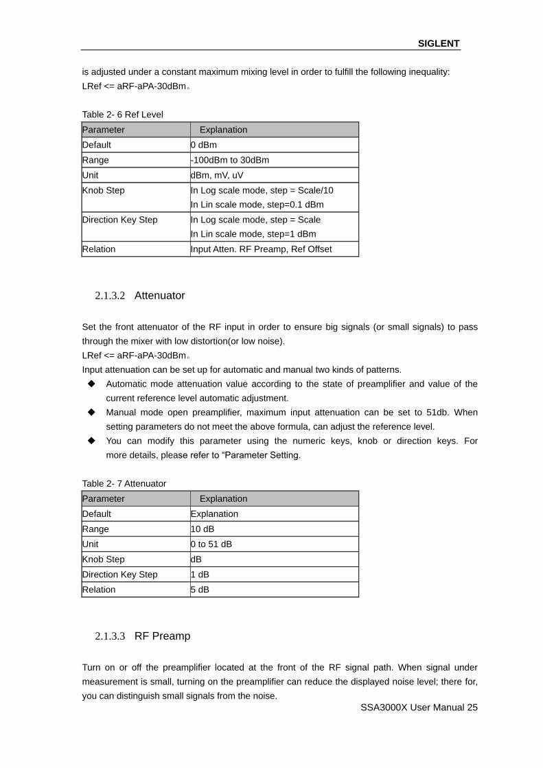
is adjusted under a constant maximum mixing level in order to fulfill the following inequality:
LRef <= aRF-aPA-30dBm。
Table 2- 6 Ref Level
Parameter Explanation
Default 0 dBm
Range -100dBm to 30dBm
Unit dBm, mV, uV
Knob Step In Log scale mode, step = Scale/10
In Lin scale mode, step=0.1 dBm
Direction Key Step In Log scale mode, step = Scale
In Lin scale mode, step=1 dBm
Relation Input Atten. RF Preamp, Ref Offset
2.1.3.2 Attenuator
Set the front attenuator of the RF input in order to ensure big signals (or small signals) to pass
through the mixer with low distortion(or low noise).
LRef <= aRF-aPA-30dBm。
Input attenuation can be set up for automatic and manual two kinds of patterns.
Automatic mode attenuation value according to the state of preamplifier and value of the
current reference level automatic adjustment.
Manual mode open preamplifier, maximum input attenuation can be set to 51db. When
setting parameters do not meet the above formula, can adjust the reference level.
You can modify this parameter using the numeric keys, knob or direction keys. For
more details, please refer to “Parameter Setting.
Table 2- 7 Attenuator
Parameter Explanation
Default Explanation
Range 10 dB
Unit 0 to 51 dB
Knob Step dB
Direction Key Step 1 dB
Relation 5 dB
2.1.3.3 RF Preamp
Turn on or off the preamplifier located at the front of the RF signal path. When signal under
measurement is small, turning on the preamplifier can reduce the displayed noise level; there for,
you can distinguish small signals from the noise.

SIGLENT
26 SSA3000X User Manual
The corresponding icon “PA” will be appear at the left side of the screen when the preamplifier
is turned on.
2.1.3.4 Units
Set the unit of the Y-axis to dBm, dBmV, dBuV, Volts and Watts. The default is dBm。
The conversion relationships between units are as follows.
dBm = 10log Volts 2
R×
1
0.001W
dBV = 20log Volts ×106
1uV
dBmV = 20log Volts ×103
1mV
Watts = Volts 2
R
Wherein, R denotes the reference resistance. Value is 50Ω
2.1.3.5 Scale
Set the logarithmic units per vertical grid division on the display. This function is only available
when the scale type is set to “log”. In use process pay attention to the following points:
By changing the scale, the amplitude range available is adjusted。
The range of the amplitude that can be displayed
Minimum: reference level –10 × the current scale value;
Maximum: the reference level.
You can modify this parameter using the numeric keys, knob or direction keys. For more
details, please refer to “Parameter Setting”.
Table 2- 8 Scale
Parameter Explanation
Default 10 dB
Range 0.5 to 10dB
Unit dB
Knob Step Scale≥1,Step=1 dB
Scale<1,Step=0.1 dB
Direction Key Step Scale≥1,1-2-5 sequence
Relation Scale Type

SIGLENT
SSA3000X User Manual 27
2.1.3.6 Scale Type
Set the scale type of Y-axis to Lin or Log. The default is Log.
In Lin mode, Scale value cannot be changed. Display area for reference level of 0%. In use
process pay attention to the following points:
In Log scale type, the Y-axis denotes the logarithmic coordinate; the value shown at the top of
the grid is the reference level and each grid represents the scale value. The unit of Y-axis will
automatically switch to the default unit (dBm) in Log scale type is changed from Lin to Log.
In Lin scale type, the Y-axis denotes the liner coordinate; the values shown at the top of the
grid and the bottom of the grid are the reference level and the scale setting function is invalid.
The unit of Y-axis will automatically switch to the default unit(Volts) in Lin scale type when the
scale type is charged from Log to Lin.
The scale type does not affect the unit of Y-axis.
2.1.3.7 Ref Offset
Assign an offset to the reference level to compensate for gains or losses generated between the
device under measurement and the analyzer.
The change of this value changes both the reference level readout and the amplitude readout
of the marker; but does not impact the position of the curve on the screen.
You can modify this parameter using the numeric keys. For more details, please refer to
“Parameter Setting”.
Table 2- 9 Ref Offset
Parameter Explanation
Default 0 dBm
Range -100~ 100dBm
Unit dBm
Knob Step 1 dBm
Direction Key Step 10dBm
Relation none
2.1.3.8 Correction
Correct the amplitude in order to compensate for the gain or loss from external devices such as
Antenna and Cable. When using this function, you can view the correction data table and save or
load the current correction data. When amplitude correction is turn on, both the trace and related
measurement results will be corrected.
1. Select
Select a correction factor from Antenna, Cable, Other and User for the current correction and the
default is off (turn off all the correction factors). After choosing the desired correction factors, press
“Correction” to enable the correction factors selected. Multiple correction factors can be enabled
the same time.

SIGLENT
28 SSA3000X User Manual
2. Correction
Enable or disable amplitude correction and the default is off. When amplitude correction is enabled,
the data of the correction factor currently selected is used for amplitude correction. If multiple
factors are enabled, all related data will be used for amplitude correction.
2.1.4 Auto Tune
Search for signals automatically throughout the full frequency range; adjust the frequency and
amplitude for optimum display effect of the signal to realize one-key signal search and auto setting
of parameters.
In the process of auto search, The “Auto Tune” is shown in the status bar on the screen until
the search is finished.
Some parameters such as the reference level, scale, input attenuation and maximum mixing
level may be changed during the auto search.

SIGLENT
SSA3000X User Manual 29
Figure 2- 3 Before Auto Tune
Figure 2- 4 After Auto Tune
SIGLENT
30 SSA3000X User Manual
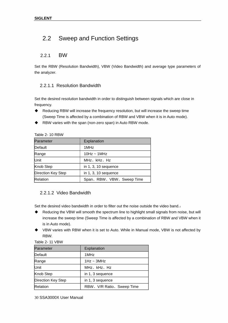
2.2 Sweep and Function Settings
2.2.1 BW
Set the RBW (Resolution Bandwidth), VBW (Video Bandwidth) and average type parameters of
the analyzer.
2.2.1.1 Resolution Bandwidth
Set the desired resolution bandwidth in order to distinguish between signals which are close in
frequency.
Reducing RBW will increase the frequency resolution, but will increase the sweep time
(Sweep Time is affected by a combination of RBW and VBW when it is in Auto mode).
RBW varies with the span (non-zero span) in Auto RBW mode.
Table 2- 10 RBW
Parameter Explanation
Default 1MHz
Range 10Hz ~ 1MHz
Unit MHz、kHz、Hz
Knob Step in 1, 3, 10 sequence
Direction Key Step in 1, 3, 10 sequence
Relation Span、RBW、VBW、Sweep Time
2.2.1.2 Video Bandwidth
Set the desired video bandwidth in order to filter out the noise outside the video band.:
Reducing the VBW will smooth the spectrum line to highlight small signals from noise, but will
increase the sweep time (Sweep Time is affected by a combination of RBW and VBW when it
is in Auto mode).
VBW varies with RBW when it is set to Auto. While in Manual mode, VBW is not affected by
RBW.
Table 2- 11 VBW
Parameter Explanation
Default 1MHz
Range 1Hz ~ 3MHz
Unit MHz、kHz、Hz
Knob Step in 1, 3 sequence
Direction Key Step in 1, 3 sequence
Relation RBW、V/R Ratio、Sweep Time

SIGLENT
SSA3000X User Manual 31
2.2.1.3 V/R Ratio
Set the ratio of VBW to RBW. This value is different while measuring different kinds of signals:
Sine signal: use 1 to 3 (for faster sweeps)
Pulse signal: use 10 (to reduce the influence on the amplitude of transient signals)
Noise signal: generally use 0.1 (to obtain the average of noises)
Table 2- 12 V/R Ratio
Parameter Explanation
Default 1
Range 0.001 ~ 1000
Unit N/A
Knob Step in 1, 3, 10 sequence
Direction Key Step in 1, 3, 10 sequence
Relation RBW VBW
2.2.1.4 Average Type
Chooses one of the following averaging type: log power (video), power (RMS), or voltage
averaging. When trace average is on, the average type is shown on the left side of the display.
1. Log Power
Selects the logarithmic (decibel) scale for all filtering and averaging processes. This scale is
"Video" because it is the most common display and analysis scale for the video signal within a
spectrum analyzer. This scale is excellent for finding CW signals near noise.
2. Power Average
In this average type, all filtering and averaging processes work on the power(the square of the
magnitude) of the signal, instead of its log or envelope voltage. This scale is best for measuring
the true time power of complex signals.
3. Voltage Average
In this Average type, all filtering and averaging processes work on the voltage of the envelope of
the signal. This scale is good for observing rise and all behavior of AM or pulse-modulated signals
such as radar and TDMA transmitters.
2.2.2 Trace
The sweep signal is displayed as a trace on the screen.

SIGLENT
32 SSA3000X User Manual
2.2.2.1 Select Trace
Spectrum Analyzer allows for up to four traces to be displayed at the same time. Each trace has its
own color (Trace 1 - Yellow, Trace 2 - Purple, Trace 3 - Light blue and Trace 4 - Green). All traces
can be set parameter independently. As a default, spectrum analyzer will choose Trace A and set
the type of the trace as Clear Write
2.2.2.2 Trace Type
Set the type of the current trace or disable it. The system calculates the sampled data using a
specific operation method according to the trace type selected and displays the result. Trace types
include Clear Write, Max Hold, Min Hold, View, Average and Bank. The corresponding icon of the
trace type will be displayed in the status bar at the left of the screen. Take Trace 1,2,3,4 as an
example and the icons are as shown in the figure below.
Figure 2- 5 Trace Type
1. Clear Write
Erases any data previously stored in the selected trace, and display the data sampled in real-time
of each point on the trace.
2. Max Hold
Retains the maximum level for each trace point of the selected trace. Updates the data if a new
maximum level is detected in successive sweeps.
3. Min Hold

SIGLENT
SSA3000X User Manual 33
Display the minimum from multiple sweeps for each point of the trace and update the data if a new
minimum is generated in successive sweeps.
4.View
Holds and displays the amplitude data of the selected trace. The trace data is not updated as the
analyzer sweeps.
5.Bank
Disable the trace display and all measurements of this trace.
2.2.2.3 Average Times
Set the number of averages of the selected trace.
More averages can reduce the noise and the influence of other random signals; thus
highlighting the stable signal characteristics. The larger the number of averages is, the
smoother the trace will be.
Table 2- 13 Average Times
Parameter Explanation
Default 100
Range 1 ~ 999
Unit N/A
Knob Step N/A
Direction Key Step N/A
2.2.2.4 Math
Set the computational method of the math trace.
1. Variable X、Y
Variable X、Y can be A, B, C.
2. Const
Set the value of the constant.
Table 2- 14 Const
Parameter Explanation
Default 0dB
Range -300 dB ~ 300 dB
Unit dB
3. Output Z
The result Z will shown on screen in trace A、B、C as you choose.
4. Calculation Type
Spectrum Analyzer provides the calculation types as shown bellow:
X-Y+Ref→Z
Y-X+Ref→Z

SIGLENT
34 SSA3000X User Manual
X+Y-Ref→Z
X+const→Z
X-const→Z
2.2.3 Detect
2.2.3.1 Detect Type
The analyzer displays the sweep signal on the screen in the form of trace. For each trace point, the
analyzer always captures all the data within a specific time interval and processes (Peak, Average,
etc.) the capture data using the detector currently selected, then display the processed data (one
point) on the screen .
Select an appropriate detector type according to the actual application in order to ensure the
accuracy of the measurement.
The available types are Pos Peak, Neg Peak, Sample, Normal, Average. The default is Pos
peak.
Positive Peak
For each trace point, Positive Peak detector displays the maximum value of data sampled
within the corresponding time interval.
Negative Peak
For each trace point, Negative Peak detector displays the minimum value of data sampled
within the corresponding time interval.
Sample
For each trace point, Sample detector displays the transient level corresponding to the central
time point of the corresponding time interval. This detector type is applicable to noise or noise-like
signal.
Normal
Normal detector (also called rosenfell detector) displays the maximum value and the minimum
value of the sample data segment in turn; namely for an odd-numbered data point, the maximum
value is displayed; for an even-numbered data point, the minimum value is displayed. In this way,
the amplitude variation range of the signal is clearly shown.
Average
For each trace point, Average detector displays the average value of data sampled within the
corresponding time interval.
2.2.4 Sweep
Set parameters about the Sweep functions, including sweep time, sweep rule, sweep mode,
number of sweep, etc.

SIGLENT
SSA3000X User Manual 35
2.2.4.1 Sweep Time
Set the time needed for the spectrum analyzer to finish a sweep within the span range. The sweep
time can be set in “Auto” or “Manual” mode and the default is “Auto”.
In non-zero span, the analyzer selects the shortest sweep time on the basis of the current
RBW and VBW settings if Auto is selected.
Decreasing the sweep time would speed the measurement. However, an error may be caused
if the specified sweep time is less than the minimum sweep time in Auto coupling; at this point,
“UNCAL” is shown in the status bar on the screen
Table 2- 15 Sweep Time
Parameter Explanation
Default 50ms
Range 917us ~ 3000 s
Unit ks、s、ms、us、ns
Knob Step Sweep time/100,min =1 ms
Direction Key Step in 1,3 sequence
2.2.4.2 Sweep Rule
The analyzer provides two sweep time rules to meet the different sweep time requirements:
Speed: Activates the default fast sweep time rule.
Accuracy: Activates the normal sweep time rule to ensure the measurement accuracy. Speed
sweep time rule provides a fast measurement function that decreases the sweep time. Using Fast
Sweep will decrease the measurement accuracy.
2.2.4.3 Sweep
Set sweep mode in single or continuous,the default is continuous. The corresponding icon of the
sweep will be displayed in the status bar at the left of the screen.
Single
1. Single
Set the sweep mode to “Single”. The number on the parameter icon denotes the current
sweep number.
2.Numbers
Set the number of sweeps for a single sweep. In single sweep mode, the system executes the
specified number of sweeps and the number shown on the icon in the status bar at the left of
the screen varies with the process of the sweep.
Continue
Set the sweep mode to “Continue”. The character Cont on the parameter icon denotes the
analyzer is sweeping continuously.
If the instrument is in single sweep mode and no measurement function is enabled, press this
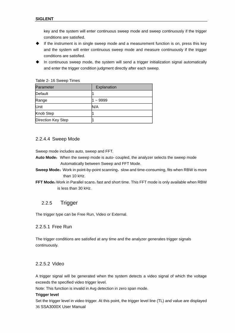
SIGLENT
36 SSA3000X User Manual
key and the system will enter continuous sweep mode and sweep continuously if the trigger
conditions are satisfied.
If the instrument is in single sweep mode and a measurement function is on, press this key
and the system will enter continuous sweep mode and measure continuously if the trigger
conditions are satisfied.
In continuous sweep mode, the system will send a trigger initialization signal automatically
and enter the trigger condition judgment directly after each sweep.
Table 2- 16 Sweep Times
Parameter Explanation
Default 1
Range 1 ~ 9999
Unit N/A
Knob Step 1
Direction Key Step 1
2.2.4.4 Sweep Mode
Sweep mode includes auto, sweep and FFT.
Auto Mode:When the sweep mode is auto- coupled, the analyzer selects the sweep mode
Automatically between Sweep and FFT Mode.
Sweep Mode:Work in point-by-point scanning,slow and time-consuming, fits when RBW is more
than 10 kHz.
FFT Mode:Work in Parallel scans,fast and short time. This FFT mode is only available when RBW
is less than 30 kHz.
2.2.5 Trigger
The trigger type can be Free Run, Video or External.
2.2.5.1 Free Run
The trigger conditions are satisfied at any time and the analyzer generates trigger signals
continuously.
2.2.5.2 Video
A trigger signal will be generated when the system detects a video signal of which the voltage
exceeds the specified video trigger level.
Note: This function is invalid in Avg detection in zero span mode.
Trigger level
Set the trigger level in video trigger. At this point, the trigger level line (TL) and value are displayed
SIGLENT
SSA3000X User Manual 37
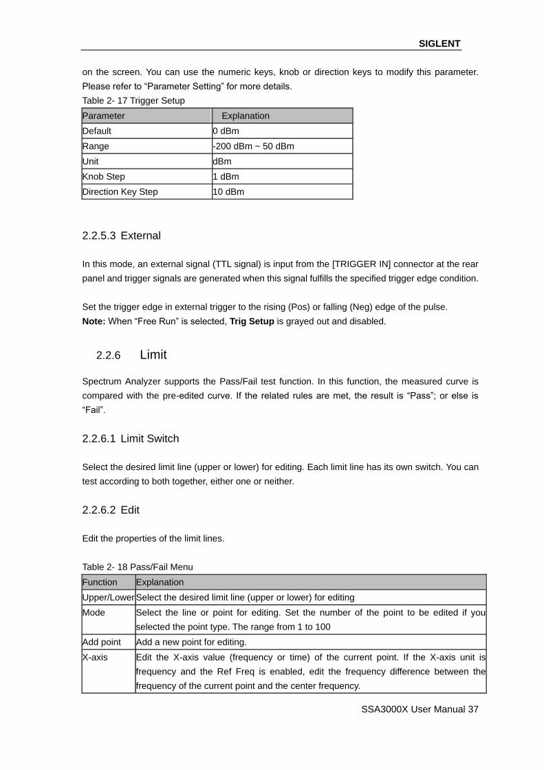
on the screen. You can use the numeric keys, knob or direction keys to modify this parameter.
Please refer to “Parameter Setting” for more details.
Table 2- 17 Trigger Setup
Parameter Explanation
Default 0 dBm
Range -200 dBm ~ 50 dBm
Unit dBm
Knob Step 1 dBm
Direction Key Step 10 dBm
2.2.5.3 External
In this mode, an external signal (TTL signal) is input from the [TRIGGER IN] connector at the rear
panel and trigger signals are generated when this signal fulfills the specified trigger edge condition.
Set the trigger edge in external trigger to the rising (Pos) or falling (Neg) edge of the pulse.
Note: When “Free Run” is selected, Trig Setup is grayed out and disabled.
2.2.6 Limit
Spectrum Analyzer supports the Pass/Fail test function. In this function, the measured curve is
compared with the pre-edited curve. If the related rules are met, the result is “Pass”; or else is
“Fail”.
2.2.6.1 Limit Switch
Select the desired limit line (upper or lower) for editing. Each limit line has its own switch. You can
test according to both together, either one or neither.
2.2.6.2 Edit
Edit the properties of the limit lines.
Table 2- 18 Pass/Fail Menu
Function Explanation
Upper/Lower Select the desired limit line (upper or lower) for editing
Mode Select the line or point for editing. Set the number of the point to be edited if you
selected the point type. The range from 1 to 100
Add point Add a new point for editing.
X-axis Edit the X-axis value (frequency or time) of the current point. If the X-axis unit is
frequency and the Ref Freq is enabled, edit the frequency difference between the
frequency of the current point and the center frequency.

SIGLENT
38 SSA3000X User Manual
Amplitude Edit the amplitude of the current point or line. If the Ref AMPT is enabled, edit the
amplitude difference between the amplitude of the current point and the reference
level.
Del Point Delete the point you are editing.
Del All Delete all point.
Save/Recall Save or load the limit file.
2.2.6.3 Test
Enable or disable the limit test function.
2.2.6.4 Setup
Fail to stop
Select whether to perform the next sweep if the test fails.
Buzzer
Turn on or off the buzzer. When the buzzer is on, it beeps when the test fails.
X Axis
Set the X-axis unit to frequency or time unit.
Note that all the points of the current limit line will be deleted when the X-axis unit changes.
2.2.7 TG
Set the parameter related to the tracking generator (TG).
2.2.7.1 TG
TG is used to enable or disable the TG. When the TG is enabled, a signal with the same frequency
of the current sweep signal will be output from the [GEN OUTPUT 50Ω] connector at the front
panel. The power of the signal could be set through the menu.
2.2.7.2 TG Level
Set the output power of the signal of the tracking generator. You can use the numeric keys, knob or
direction keys to modify this parameter. For more details, please refer to “Parameter Setting”.
Table 2- 19 TG Level
Parameter Explanation
Default 0 dB
Range -200 dB ~ 200 dB
Unit dB
Knob Step 1 dB
Direction Key Step 10 dB

SIGLENT
SSA3000X User Manual 39
2.2.7.3 TG Level Offset
Assign a certain offset to the output power of the TG when gains or losses occur between the TG
output and external device in order to display the actual power value.
This parameter only changes the readout of the TG output power, rather than the actual value
of it.
The offset could be either a positive (gain in the external output) or a negative (loss in the
external output).
You can use the numeric keys, knob or direction keys to modify this parameter. For more
details, please refer to “Parameter Setting”.
Table 2- 20 TG Level Offset
Parameter Explanation
Default 0 dB
Range -200 dB ~ 200 dB
Unit dB
Knob Step 1 dB
Direction Key Step 10 dB
2.2.7.4 Normalize
Normalization can eliminate the error of TG Level. Before using this function, connect the [GEN
OUTPUT 50Ω] output terminal of the TG with the [RF INPUT 50Ω] input terminal of the analyzer.
1.Normalize
Enable or disable the normalization. When enabled, the reference trace will be stored
automatically after the current sweep finishes if no reference trace is stored before. During the
reference trace storage, the corresponding prompt message is displayed. When normalization is
enabled, the corresponding value of the reference trace will be subtracted from the trace data after
every sweep.
2.Norm Ref Lvl
Adjust the vertical position of the trace on the screen by adjusting the reference level when
normalization is enabled.
Being different from the Ref Level function in the AMPT menu, this parameter has no influence on
the reference level of the analyzer.
You can use the numeric keys, knob or direction keys to modify this parameter. For more details,
please refer to “Parameter Setting”.

SIGLENT
40 SSA3000X User Manual
Table 2- 21 Reference level under normalization
Parameter Explanation
Default 0 dB
Range -200 dB ~ 200 dB
Unit dB
Knob Step 1 dB
Direction Key Step 10 dB
2.Norm Ref Pos
Adjust the vertical position of the normalization reference level on the screen by adjusting the
reference position when normalization is enabled.
The function of this menu is similar to that of Norm Ref Lvl. When it is set to 0%, the
normalization reference level is displayed at the bottom of the screen grid and at the top when
it is set to 100%.
You can use the numeric keys, knob or direction keys to modify this parameter. For more
details, please refer to “Parameter Setting”.
Table 2- 22 TG reference position
Parameter Explanation
Default 100%
Range 0 ~ 100%
Unit 100%
Knob Step 1%
Direction Key Step 10%
3.Ref Trace
Set whether to display the reference trace or not. If “View” is selected, the reference trace saved
(Trace D) will be shown in “View” type.
Note: When normalization is enabled, the unit of Y-axis is “dB” and will not be influenced by the
definition in AMPT->Units. At this point, “(dB)” is displayed under the Y-axis scale in the user
interface.
2.2.8 Demod
Press Demod at the front panel to enter the demodulation setting menu. Both AM and FM
demodulations are available in this device.
2.2.8.1 Demod(AM/FM)
Set the demodulation type to AM or FM; or disable the demodulation function. The default is off.
The system will enable a marker automatically, place it at the center frequency and perform
AM (or FM) demodulation on this frequency point after you enable AM (or FM) demodulation.

SIGLENT
SSA3000X User Manual 41
Analyzer provides earphone jack and the demodulated signal can be output in audio
frequency (AF) mode through the earphone. The frequency and intensity of AF denotes the
frequency and amplitude of the signal respectively.
2.2.8.2 Earphone
Set the status of the earphone. When it is on, the demodulated signal can be heard through the
earphone during the demodulation. By default, it is off.
2.2.8.3 Volume
Set the volume of the earphone.
Table 2- 23 Volume
Parameter Explanation
Default 6
Range 0 ~ 10
Unit N/A
Knob Step 1
Direction Key Step 1
2.2.8.4 Demod Time
Set the time for the analyzer to complete a signal demodulation after each sweep. If Earphone is
set to “On”, you will hear the demodulated signal through the earphone during the demodulation.
You can use the numeric keys, knob or direction keys to modify this parameter. For more details,
please refer to “Parameter Setting”.
Table 2- 24 Demod time
Parameter Explanation
Default 5ms
Range 5ms ~ 1000s
Unit ks、s、ms
Knob Step 0 ms ~ 100 ms,step=1 ms;
100 ms ~ 1 s,step =10 ms;
1 s ~ 10 s,step =100 ms;
10 s ~ 100 s,step =1 s;
100 s ~ 1000 s,step =10 s
Direction Key Step 1-2-5 step
SIGLENT
42 SSA3000X User Manual
2.3 Marker Setup
2.3.1 Marker
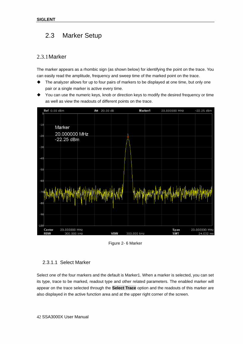
The marker appears as a rhombic sign (as shown below) for identifying the point on the trace. You
can easily read the amplitude, frequency and sweep time of the marked point on the trace.
The analyzer allows for up to four pairs of markers to be displayed at one time, but only one
pair or a single marker is active every time.
You can use the numeric keys, knob or direction keys to modify the desired frequency or time
as well as view the readouts of different points on the trace.
Figure 2- 6 Marker
2.3.1.1 Select Marker
Select one of the four markers and the default is Marker1. When a marker is selected, you can set
its type, trace to be marked, readout type and other related parameters. The enabled marker will
appear on the trace selected through the Select Trace option and the readouts of this marker are
also displayed in the active function area and at the upper right corner of the screen.

SIGLENT
SSA3000X User Manual 43
Table 2- 25 Marker parameters
Parameter Explanation
Default Center Frequency
Range 0 ~ Full Span
Unit Readout = Frequency (or Period), units available are GHz, MHz, kHz, Hz (or s, ms,
us, ns, ps)
Readout = Time, units available are s, ms, us, ns, ps
Knob Step Readout = Frequency (or Period), Step = Span/(Sweep Points - 1)
Readout = Time, Step = Sweep Time/(Sweep Points - 1)
Direction
Key Step
Readout = Frequency (or Period), Step = Span/10
Readout = Time, Step = Sweep Time /10
2.3.1.2 Select Trace
Select the trace to be marked by the current marker from A,B,C,D.
2.3.1.3 Normal
One of the marker types. It is used to measure the X (Frequency or Time) and Y (Amplitude)
values of a certain point on the trace. When selected, a marker with the number of the current
marker (such as “1”) appears on the trace.
If no active marker exists currently, a marker will be enabled automatically at the center
frequency of the current trace.
You can use the numeric keys, knob or direction keys to move the marker. The readouts of the
marker will be displayed at the upper right corner of the screen.
The readout resolution of the X-axis (frequency or time) is related to the span. For higher
readout resolution, reduce the span.
2.3.1.4 Delta
One of the marker types. It is used to measure the delta values of X (Frequency or Time) and Y
(Amplitude) between the reference point and a certain point on the trace. When selected, a pair of
markers appears on the trace: Reference Marker (marked by a combination of the marker number
and letter “R”, such as “1R”) and the Delta Marker (marked by the marker number, such as “1”).
A reference marker will be activated at the position of the current marker if an active marker
currently exists; or else both the reference marker and delta marker will be simultaneously
activated at the center frequency.
The location of the reference marker is always fixed (both on the X-axis and the Y-axis); while
the Delta Marker is active. You can use the numeric keys, knob or direction keys to change
the location of the Delta Marker.
The frequency (or time) delta and amplitude delta between the two markers are displayed at
the upper right corner of the screen.
There are two methods for defining a point as the reference point:

SIGLENT
44 SSA3000X User Manual
a) Open a “Normal” marker and locate it onto a point. Then, switch the marker type to “Delta”;
at this time, this point is the reference point. You can modify the location of the delta point to
achieve delta measurement.
b) Open a “Delta” marker and locate it onto a point. Then, reselect the Delta menu to locate
the reference marker onto this point. You can modify the location of the delta point to achieve
delta measurement.
When the Noise Marker function under the Marker Fn menu is activated, the result of the
noise measurement will be corrected automatically and be normalized to 1 Hz.
The application of “Delta” marker
Measure the signal-noise ratio of single spectrum signal: Place the reference and delta Markers
onto the signal and noise respectively, the amplitude in the measurement result is the signal-noise
ratio.
2.3.1.5 Delta Pair
One of the marker types. When selected, a pair of markers will appear on the trace: Reference
Marker (marked by a combination of the marker number and letter “R”, such as “1R”) and the Delta
Marker (marked by the marker number, such as “1”).
You can use the numeric keys, knob or direction keys to set the locations of the reference
marker (selecting “Ref”) , the delta marker (selecting “Delta”), the span of marker
pair(selecting “Span”) and the center of marker pair(selecting “Center”) respectively.
This is different from the Delta type marker in that you can modify both the reference
(selecting “Ref”) and delta (selecting “Delta”) points or modify both them at the same
time(selecting “Span” or “Center”). Additionally, both the X and Y values of the reference
marker are stable for “Delta” marker during the sweep; but the Y value of the reference marker
updates along with the sweep for “Delta Pair” marker
If “Span” is selected, setting the “Span Pair” will keep the center position of the two markers
unchanged and move them towards the two sides (value increases) or the middle (value
decreases).
If “Center” is selected, setting the “Span Pair” will keep the relative distance between the two
markers unchanged and move their center position left (value decreases) or right (value
increases).
2.3.1.6 Relative To
Relative to is used to measure the delta values of X (Frequency or Time) and Y (Amplitude)
between two markers which mark on different traces.

SIGLENT
SSA3000X User Manual 45
2.3.1.7 Off
Turn off the marker currently selected. The marker information displayed on the screen and
functions based on the marker will also be turned off.
2.3.1.8 Marker Table
Enable or disable the Marker Table.
Display all the markers enabled on the lower portion of the screen, including marker number, trace
number, marker readout type, X-axis readout and amplitude. Through this table you can view the
measurement values of multiple points. The table allows for up to eight markers to be displayed at
one time.
Figure 2- 7 Marker table
2.3.2 Marker ->
2.3.2.1 M->CF
Set the center frequency of the analyzer to the frequency of the current marker.
If Normal marker is selected, the center frequency will be set to the frequency of the current
SIGLENT
46 SSA3000X User Manual
marker.
If Delta, or Delta Pair marker is selected, the center frequency will be set to the frequency of
the Delta Marker.
The function is invalid in Zero span mode.
2.3.2.2 M -> CF Step
Set the center frequency step of the analyzer to the frequency of the current marker.
If Normal marker is selected, the center frequency step will be set to the frequency of the
current marker.
If Delta, or Delta Pair marker is selected, the center frequency step will be set to the
frequency of the Delta Marker.
The function is invalid in Zero span mode.
2.3.2.3 M -> Start Freq
Set the start frequency of the analyzer to the frequency of the current marker.
If Normal marker is selected, the start frequency will be set to the frequency of the current
marker.
If Delta, or Delta Pair marker is selected, the start frequency will be set to the frequency of the
Delta Marker.
The function is invalid in Zero span mode.
2.3.2.4 M -> Stop Freq
Set the stop frequency of the analyzer to the frequency of the current marker.
If Normal marker is selected, the stop frequency will be set to the frequency of the current
marker.
If Delta, or Delta Pair marker is selected, the stop frequency will be set to the frequency of the
Delta Marker.
The function is invalid in Zero span mode.
2.3.2.5 M ->Ref Level
Set the reference level of the analyzer to the amplitude of the current marker.
If Normal marker is selected, the reference level will be set to the amplitude of the current
marker.
If Delta, or Delta Pair marker is selected, the reference level will be set to the amplitude of the
Delta Marker.

SIGLENT
SSA3000X User Manual 47
2.3.2.6 ΔM->Span
Set the span of the analyzer to the frequency difference between the two markers in Delta, or
Delta Pair marker type.
If Normal marker is selected, this function is invalid.
The function is invalid in Zero span mode.
2.3.2.7 ΔM->CF
Set the center frequency of the analyzer to the frequency difference between the two markers in
Delta, or Delta Pair, marker type.
If Normal marker is selected, this function is invalid.
The function is invalid in Zero span mode.
2.3.3 Marker Fn
Special marker functions including Noise Marker, N dB BW and Freq Count.
2.3.3.1 Select Marker
Select one of the four markers (1, 2, 3, 4) and the default is Marker1.
2.3.3.2 Noise Marker
Execute the Noise marker function for the selected marker and read the noise power spectral
density.
If the current marker is “Off” in the Marker menu, pressing Noise Marker will first set it to
Normal type automatically; then measure the average noise level at the marked point and
normalize this value to 1 Hz bandwidth. During this process, certain compensation is always
made on the basis of the detection and trace types. The measurement will be more precise if
RMS Avg or Sample detection type is used.
This function can be used for measuring the C/N ratio.
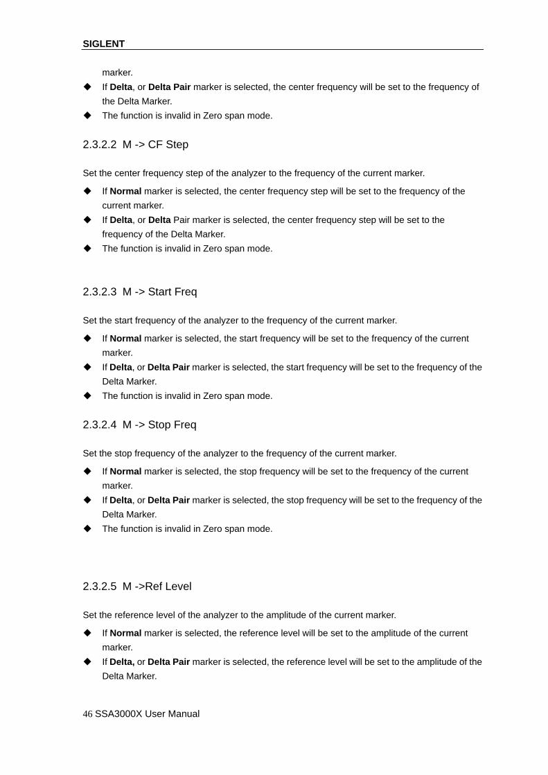
2.3.3.3 N dB BW
Enable the N dB BW measurement or set the value of N dB. The N dB BW denotes the frequency
difference between two points that are located on both sides of the current marker and with N dB
fall (N<0) or rise (N>0) in amplitude as shown in the figure on the next page.
SIGLENT
48 SSA3000X User Manual
Figure 2- 8 N dB BW
When the measurement starts, the analyzer will search for the two points which are located at
both sides of the current point with N dB fall or rise in amplitude and display the frequency
difference between the two points in the active function area. "----" would be displayed if the
search fails.
You can use the numeric keys, knob or direction keys to modify the value of N, for more
details please refer to “Parameter Setting”.
Table 2- 26 N dB Noise
Parameter Explanation
Default -3dB
Range -100dB ~ 100dB
Unit dB
Knob Step 0.1
Direction Key Step 1dB
2.3.3.4 Freq Counter
Turn on or off the frequency counter.
The function is invalid when selecting marker 2, 3, 4.
If marker 1 is selected but no active, turning on the frequency counter will open marker 1
Normal marker automatically.
The frequency readout is more accurate when the frequency counter is enabled.
SIGLENT
SSA3000X User Manual 49
The frequency counter measures the frequency near the center frequency in Zero span mode.
2.3.3.5 Off
Turn off the noise marker enabled , N dB BW measurement or Frequency Counter, but not the
marker itself.
2.3.3.6 Read Out
Select a desired readout type of the X-axis for the marker and different markers can use different
readout types. This setting will change the readout type and affect the marker readings in the
active function area and at the upper right corner of the screen, but will not change the actual
value.
1. Frequency
In this type, Normal marker shows the absolute frequency; while Delta marker and Delta Pair
marker show the frequency difference between the delta marker and reference marker. The default
readout mode in non-zero span mode is “Frequency”.
Note: This type is invalid in Zero span mode.
2. Period
In this type, Normal marker shows the reciprocal of frequency; while Delta marker and Delta Pair
marker show the reciprocal of frequency difference. When the frequency difference is zero, the
reciprocal is infinite and 100 Ts is displayed.
Note: This type is invalid in Zero span mode.
3. Δ Time
In this type, Normal marker shows the time difference between the marker and the start of the
sweep; while Delta marker and Delta Pair marker show the sweep time difference between the
delta marker and reference marker.
The default readout mode in Zero span mode is Δ Time.
2.3.4 Peak
Open the peak search setting menu and execute peak search.
2.3.4.1 Peak -> CF
Execute peak search and set the center frequency of the analyzer to the frequency of the peak.
2.3.4.2 Next Peak

SIGLENT
50 SSA3000X User Manual
Search for and mark the peak whose amplitude is closest to that of the current peak and which
meets the peak search condition.
2.3.4.3 Next Left Peak
Search for and mark the nearest peak which is located at the left side of the current peak and
meets the peak search condition.
2.3.4.4 Next Right Peak
Search for and mark the nearest peak which is located at the right side of the current peak and
meets the peak search condition.
2.3.4.5 Peak Peak
Execute peak search and minimum search at the same time and mark the results with delta pair
markers. Wherein, the result of peak search is marked with the delta marker and the result of
minimum search is marked with the reference marker.
2.3.4.6 Count Peak
Enable or disable continuous peak search and the default is Off. When enabled, the system will
always execute a peak search automatically after each sweep in order to track the signal under
measurement.
2.3.4.7 Peak Table
Open the peak table (in the lower window) which lists the peaks (with frequency and amplitude)
that meet the peak search condition. Up to 16 peaks can be displayed in the table.
2.3.4.8 Search Config
Define the conditions of peak search for various peak searches. A real peak should meet the
requirements of both the “Peak Excursion” and “Peak Threshold”.
1. Peak Threshold
Assign a minimum for the peak amplitude. Peaks whose amplitudes are greater than the specified
peak threshold are treated as real peaks.
Table 2- 27 Peak Threshold
Parameter Explanation
Default -140dBm
Range -200dBm ~ 200dBm
Unit dBm
Knob Step 1dBm
Direction Key Step 5dBm

SIGLENT
SSA3000X User Manual 51
2. Peak Excursion
Set the excursion between the peak and the minimum amplitude on both sides of it. Peaks whose
excursions are beyond the specified excursion are treated as real peaks.
Table 2- 28 Peak Excursion
Parameter Explanation
Default 10dB
Range 0dB ~ 200dB
Unit dB
Knob Step 1dB
Direction Key Step 5dB
3. Peak Type
Set the peak search condition. The available options are Maximum and Minimum

SIGLENT
52 SSA3000X User Manual
2.4 Measurement
2.4.1 Meas
Provide measurement function, the screen will be divided into two parts, the above part is measure
screen, displaying trace, the other part is used to display result of a measurement.
2.4.1.1 Channel Power
Measure the power and power density within the specified channel bandwidth. When this function
is enabled, the span and resolution bandwidth are automatically adjusted to smaller values. Select
Channel Power and press Meas Setup to set the corresponding parameters.
2.4.1.2 ACPR
Measure the powers of the main channel and adjacent channels as well as the power difference
between the main channel and each of the adjacent channels. When this function is enabled, the
span and resolution bandwidth of the analyzer are adjusted to smaller values automatically.
Select ACPR and press Meas Setup to set the corresponding parameters.
2.4.1.3 Occupied BW
Integrate the power within the whole span and calculate the bandwidth occupied by this power
according to the specified power ratio. The OBW function also indicates the difference (namely
“Transmit Freq Error”) between the center frequency of the channel under measurement and the
center frequency of the analyzer. Select Occupied BW and press Meas Setup to set the
corresponding parameters.
2.4.1.4 T-Power
The system enters zero span mode and calculates the power within the time domain. The types of
powers available include Peak, Average and RMS. Select T-Power and press Meas Setup to set
the corresponding parameters.
2.4.1.5 Meas Off
Turn off all the Meas function.
2.4.2 Meas setup
2.4.2.1 Channel Power
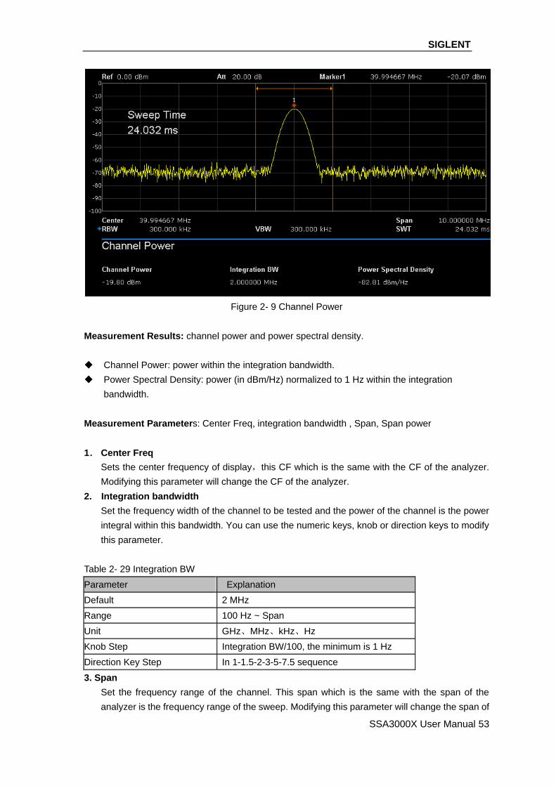
SIGLENT
SSA3000X User Manual 53
Figure 2- 9 Channel Power
Measurement Results: channel power and power spectral density.
Channel Power: power within the integration bandwidth.
Power Spectral Density: power (in dBm/Hz) normalized to 1 Hz within the integration
bandwidth.
Measurement Parameters: Center Freq, integration bandwidth , Span, Span power
1. Center Freq
Sets the center frequency of display,this CF which is the same with the CF of the analyzer.
Modifying this parameter will change the CF of the analyzer.
2. Integration bandwidth
Set the frequency width of the channel to be tested and the power of the channel is the power
integral within this bandwidth. You can use the numeric keys, knob or direction keys to modify
this parameter.
Table 2- 29 Integration BW
Parameter Explanation
Default 2 MHz
Range 100 Hz ~ Span
Unit GHz、MHz、kHz、Hz
Knob Step Integration BW/100, the minimum is 1 Hz
Direction Key Step In 1-1.5-2-3-5-7.5 sequence
3. Span
Set the frequency range of the channel. This span which is the same with the span of the
analyzer is the frequency range of the sweep. Modifying this parameter will change the span of
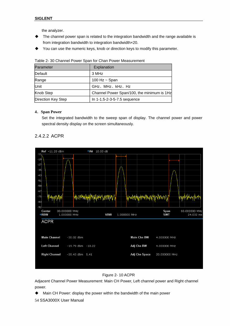
SIGLENT
54 SSA3000X User Manual
the analyzer.
The channel power span is related to the integration bandwidth and the range available is
from integration bandwidth to integration bandwidth×20.
You can use the numeric keys, knob or direction keys to modify this parameter.
Table 2- 30 Channel Power Span for Chan Power Measurement
Parameter Explanation
Default 3 MHz
Range 100 Hz ~ Span
Unit GHz、MHz、kHz、Hz
Knob Step Channel Power Span/100, the minimum is 1Hz
Direction Key Step In 1-1.5-2-3-5-7.5 sequence
4.Span Power
Set the integrated bandwidth to the sweep span of display. The channel power and power
spectral density display on the screen simultaneously.
2.4.2.2 ACPR
Figure 2- 10 ACPR
Adjacent Channel Power Measurement: Main CH Power, Left channel power and Right channel
power.
Main CH Power: display the power within the bandwidth of the main power

SIGLENT
SSA3000X User Manual 55
Left channel power : display the power of left channel and the power difference between the
left channel and the main channel (in dBc)
Right channel power: display the power of the right channel and the power difference between
the right channel and the main channel(in dBc)
Measurement parameter: center frequency, main channel bandwidth, adjacent channel bandwidth
and channel spacing
1. Center Frequency
Sets the center frequency of display,this CF which is the same with the CF of the analyzer.
Modifying this parameter will change the CF of the analyzer.
2. Main channel bandwidth
Set the bandwidth of the main channel and the power of the main channel is the power integral
within this bandwidth. You can use the numeric keys, knob and direction keys to modify this
parameter.
Table 2- 31 Main channel bandwidth
Parameter Explanation
Default 2 MHz
Range 100 Hz ~ Sweep Span
Unit GHz、MHz、kHz、Hz
Knob Step Integration BW /100,the minimum is 1 Hz
Direction Key Step In 1-1.5-2-3-5-7.5 Sequence
3. Adjacent channel bandwidth
Set the frequency width of the adjacent channels.
The adjacent channel bandwidth is related to the main channel bandwidth and the range
available is from main channel bandwidth/20 to main channel bandwidth×20.
You can use the numeric keys, knob or direction keys to modify this parameter.
Table 2- 32 adjacent channel bandwidth
Parameter Explanation
Default 2 MHz
Range 100 Hz ~ Sweep Span
Unit GHz、MHz、kHz、Hz
Knob Step Integration BW /100,the minimum is 1 Hz
Direction Key Step In 1-1.5-2-3-5-7.5 Sequence
4. Adjacent Channel space
Set the difference between the center frequency of the main channel and the center frequency of
the adjacent channels.
Adjusting this parameter will also adjust the distance between the upper/lower channel and
the main channel.
You can use the numeric keys, knob or direction keys to modify this parameter.

SIGLENT
56 SSA3000X User Manual
Table 2- 33 Adjacent channel space
Parameter Explanation
Default 2 MHz
Range 33 Hz ~ full span
Unit GHz、MHz、kHz、Hz
Knob Step Integration BW /100,the minimum is 1 Hz
Direction Key Step In 1-1.5-2-3-5-7.5 Sequence
2.4.2.3 OBW
Figure 2- 11 OBW
OBW measurement: occupied bandwidth and transmit frequency error.
Occupied Bandwidth: integrate the power within the whole span and then calculate the
bandwidth occupied by the power according to the specified power ratio.
Transmit Frequency Error: difference between the center frequency of the channel and the
center frequency of the analyzer.

SIGLENT
SSA3000X User Manual 57
2.4.2.4 T-Power
Figure 2- 12 T-Power
T-Power: namely the power of the signal from the start line to the stop line.
Measurement Parameter: center frequency, start line, stop line
1. Center Frequency
Sets the center frequency of display, this CF which is the same with the CF of the analyzer.
Modifying this parameter will change the CF of the analyzer.
2. Start line
Set the left margin (in time unit) of T-Power measurement. The data calculated under this
measurement is between the start line and stop line. You can use the numeric keys, knob or
direction keys to modify this parameter.
Table 2- 34 start line
Parameter Explanation
Default 1ms
Range 0 s ~ stop line
Unit ks、s、ms、us、ns、ps
Knob Step Sweep time/751
Direction Key Step In 1-1.5-2-3-5-7.5 Sequence
3. Stop line
Set the right margin (in time unit) of T-Power measurement. The data calculated under this
measurement is between the start line and stop line. You can use the numeric keys, knob or
direction keys to modify this parameter.
SIGLENT
58 SSA3000X User Manual
Table 2- 35 stop line
Parameter Explanation
Default 24.032ms
Range Start line ~ sweep time
Unit ks、s、ms、us、ns、ps
Knob Step Sweep time /751
Direction Key Step In 1-1.5-2-3-5-7.5 Sequence

SIGLENT
SSA3000X User Manual 59
2.5 System
2.5.1 System
Set the system parameters.
2.5.1.1 Language
SSA3000X supports multi-language menu, Chinese and English build-in help and popup
messages.
Press this key to select the desired display language.
2.5.1.2 Power On/Preset
1.Power On/Preset
Set the power on setting to” factory (default)”, “Last” or one of “user”.
Set the preset type to factory (default), “Last” or one of “User”.
Last
When “Last” is selected, settings before the last power-off would be recalled automatically at
power on.
User
Select user-defined configuration from “user1” to “user6”
If power on set to user, the device will recall the specified configuration after power on and press
Preset at the front panel under any operation interface will recall the specified preset type.
2. USER-DEFINED
Save the current instrument setting as user-defined setting into the internal non-volatile memory.
You can store and name up to 6 system states, and name every STA file.
3.Factory
When “factory” is selected, the device will recall the initial config.
2.5.1.3 Interface Config
SSA3000X support communications through LAN, USB as standard interface.
1. LAN
Config or reset corresponding parameters of LAN.
2.5.1.4 Calibration

SIGLENT
60 SSA3000X User Manual
Auto Cal
When “Auto Cal” open, SSA3000X will process self-calibration regularly. Within half an hour after
power-on, the device executes a self-calibration every 10 minutes and per hour after being
powered on for more than half an hour.
2.5.1.5 System Info
1. System Info
Product Model ,Serial and HOST ID
Software Version and Hardware Version
Calibration Date
Option Information
2.Firmware Update
Update firmware
2.5.1.6 Data and Time
The system time is displayed in “ymd”, “mdy”, “dmy” format in user interface.
2.5.1.7 Self Test
Screen Test
Test whether the screen has a dot defect using five colors: White, Red, Green, Blue and Black.
Press any key to switch the screen color and exit the test.
Keyboard Test
Enter the keyboard test interface. Press the function keys at the front panel one by one and
observe whether the corresponding key be checked. If not, an error may have occurred in that key.
To exit the test, press “<-“ four times.
LCD Test
If the keys at the front panel are transparent, when the key is pressed , the corresponding backlight
will turn on when testing it.
2.5.2 Display
Control the screen display of the analyzer, such as setting the display grid brightness.
1.Grid brightness
Control the display grid brightness.
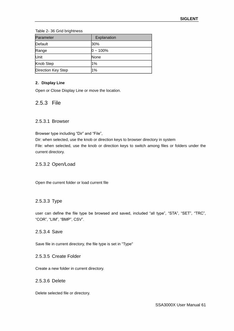
SIGLENT
SSA3000X User Manual 61
Table 2- 36 Grid brightness
Parameter Explanation
Default 30%
Range 0 ~ 100%
Unit None
Knob Step 1%
Direction Key Step 1%
2.Display Line
Open or Close Display Line or move the location.
2.5.3 File
2.5.3.1 Browser
Browser type including “Dir” and “File”,
Dir: when selected, use the knob or direction keys to browser directory in system
File: when selected, use the knob or direction keys to switch among files or folders under the
current directory.
2.5.3.2 Open/Load
Open the current folder or load current file
2.5.3.3 Type
user can define the file type be browsed and saved, included “all type”, “STA”, “SET”, “TRC”,
“COR”, “LIM”, “BMP”, CSV”.
2.5.3.4 Save
Save file in current directory, the file type is set in "Type"
2.5.3.5 Create Folder
Create a new folder in current directory.
2.5.3.6 Delete
Delete selected file or directory.

SIGLENT
62 SSA3000X User Manual
2.5.3.7 Rename
Rename the selected file or folder.
2.5.3.8 Operate
Open/Load: Open the selected folder or directory, Load the selected file
Cut : Cut the Selected file or folder, and delete the primary one after paste
Copy : Copy the Selected file or folder for paste.
Paste : Paste the file cut or copied before into the current.
Delete : Delete selected file or directory.
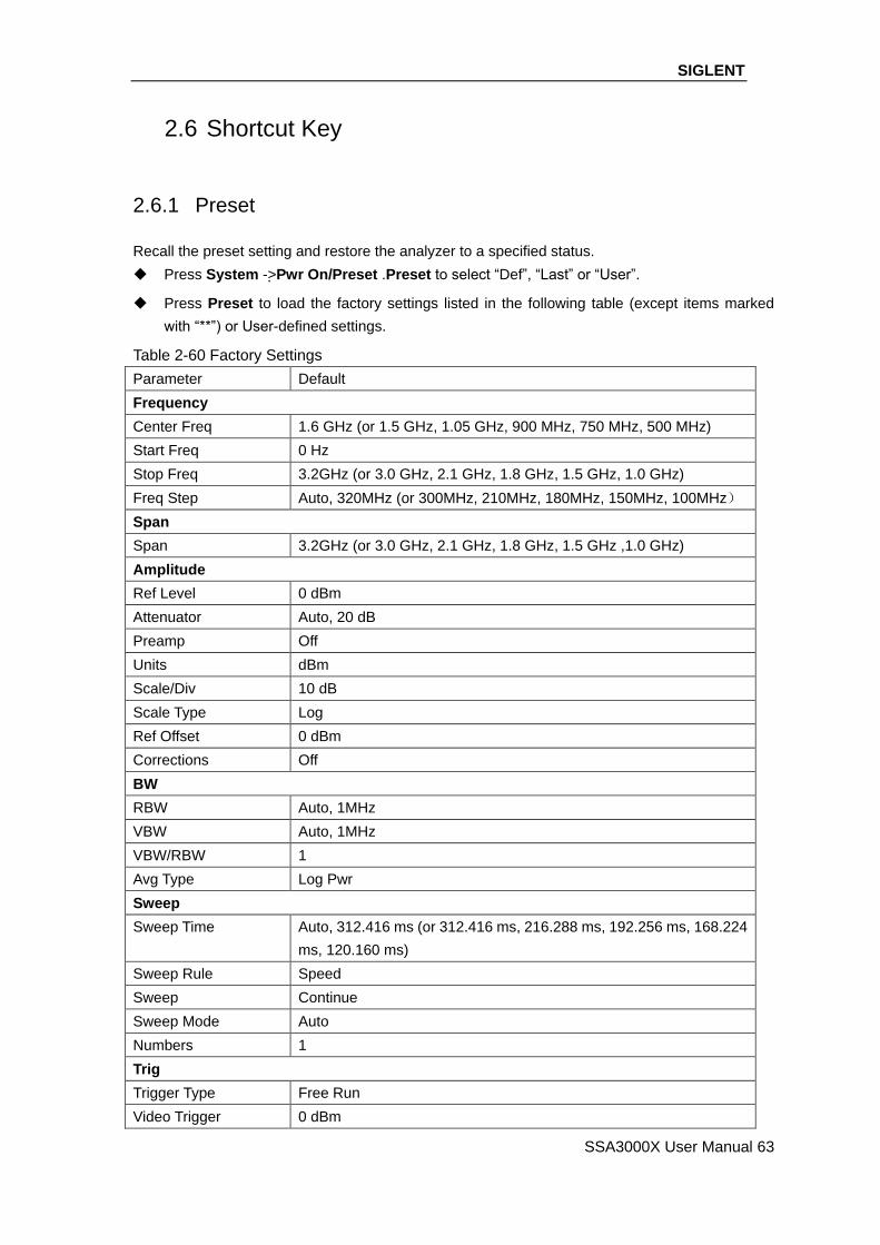
SIGLENT
SSA3000X User Manual 63
2.6 Shortcut Key
2.6.1 Preset
Recall the preset setting and restore the analyzer to a specified status.
Press System ->Pwr On/Preset .Preset to select “Def”, “Last” or “User”.
Press Preset to load the factory settings listed in the following table (except items marked
with “**”) or User-defined settings.
Table 2-60 Factory Settings
Parameter Default
Frequency
Center Freq 1.6 GHz (or 1.5 GHz, 1.05 GHz, 900 MHz, 750 MHz, 500 MHz)
Start Freq 0 Hz
Stop Freq 3.2GHz (or 3.0 GHz, 2.1 GHz, 1.8 GHz, 1.5 GHz, 1.0 GHz)
Freq Step Auto, 320MHz (or 300MHz, 210MHz, 180MHz, 150MHz, 100MHz)
Span
Span 3.2GHz (or 3.0 GHz, 2.1 GHz, 1.8 GHz, 1.5 GHz ,1.0 GHz)
Amplitude
Ref Level 0 dBm
Attenuator Auto, 20 dB
Preamp Off
Units dBm
Scale/Div 10 dB
Scale Type Log
Ref Offset 0 dBm
Corrections Off
BW
RBW Auto, 1MHz
VBW Auto, 1MHz
VBW/RBW 1
Avg Type Log Pwr
Sweep
Sweep Time Auto, 312.416 ms (or 312.416 ms, 216.288 ms, 192.256 ms, 168.224
ms, 120.160 ms)
Sweep Rule Speed
Sweep Continue
Sweep Mode Auto
Numbers 1
Trig
Trigger Type Free Run
Video Trigger 0 dBm
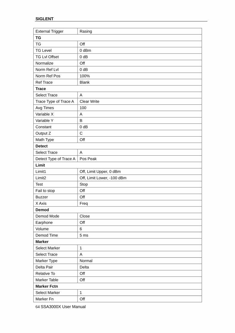
SIGLENT
64 SSA3000X User Manual
External Trigger Rasing
TG
TG Off
TG Level 0 dBm
TG Lvl Offset 0 dB
Normalize Off
Norm Ref Lvl 0 dB
Norm Ref Pos 100%
Ref Trace Blank
Trace
Select Trace A
Trace Type of Trace A Clear Write
Avg Times 100
Variable X A
Variable Y B
Constant 0 dB
Output Z C
Math Type Off
Detect
Select Trace A
Detect Type of Trace A Pos Peak
Limit
Limit1 Off, Limit Upper, 0 dBm
Limit2 Off, Limit Lower, -100 dBm
Test Stop
Fail to stop Off
Buzzer Off
X Axis Freq
Demod
Demod Mode Close
Earphone Off
Volume 6
Demod Time 5 ms
Marker
Select Marker 1
Select Trace A
Marker Type Normal
Delta Pair Delta
Relative To Off
Marker Table Off
Marker Fctn
Select Marker 1
Marker Fn Off

SIGLENT
SSA3000X User Manual 65
N dB BW -3 dB
Read Out Frequency
Peak
Cont Peak Off
Peak Table Off
Peak Threshold -140 dBm
Peak Excursion 10 dB
Peak Type Max
Mode
Mode Spec Analyzer
Measure
Meas Type Off
Measure Setup
Channel Power
Center Freq 1.6 GHz (or 1.5 GHz, 1.05 GHz, 900 MHz, 750 MHz, 500 MHz)
Integration BW 2 MHz
Span 3.2GHz (or 3.0 GHz、2.1 GHz、1.8 GHz、1.5 GHz、1.0 GHz)
ACPR
Center Freq 1.6 GHz (or 1.5 GHz, 1.05 GHz, 900 MHz, 750 MHz, 500 MHz)
Main Channel 1 MHz
Adjacent Chn 1 MHz
Adj Chn Space 3 MHz
Occupied BW
Method %
dBc 26
% 99
T-Power
Center Freq 1.6 GHz (or 1.5 GHz, 1.05 GHz, 900 MHz, 750 MHz, 500 MHz)
Start Line 0 s
Stop Line 20 ms
System**
Language English
Power On Def
Preset Def
IP Config Static
Auto Cal Close
Tine Date On
Set Format ymd

SIGLENT
66 SSA3000X User Manual
2.6.2 Couple
Set related parameters according to the coupling relationship.
Auto all : Set Related parameters automatically according to the coupling relationship.
1. RBW
RBW have couple relationship with span. Please refer to the introduction of the "Resolution
Bandwidth"
2. VBW
VBW have coupling relationship with VBW. Please refer to the introduction of "VBW".
3.Attenuation
Input attenuation have coupling relation ship with Ref Level, preamp. Please refer to introduction of
the "amplitude".
4. CF step
CF step have coupling relationship with RBW at the zero span, When in none-zero mode, CF step
have coupling relationship with Span. please refer to the introduction of the "Freq Step".
5. Sweep time
Sweep time have coupling relationship with RBW, VBW and span. Please refer to the introduction
of "Sweep Time".
2.6.3 Help
After press “Help”, press any key to help information.
2.6.4 Save
Quick saving a file.

SIGLENT
SSA3000X User Manual 67
Chapter 3 General Inspection and Troubleshooting
3.1 General Inspection
1. Inspect the shipping container
Keep the damaged shipping container or cushioning material until the contents of the shipment
have been completely checked and the instrument has passed both electrical and mechanical
tests.
The consigner or carrier will be responsible for damages to the instrument resulting from
shipment. SIGLENT will not provide free maintenance or replacement.
2. Inspect the instrument
If the instrument is found to be damaged, defective or fails in electrical or mechanical tests,
please contact SIGLENT.
3. Check the accessories
Please check the accessories according to the packing list. If the accessories are incomplete
or damaged, please contact your SIGLENT sales representative.
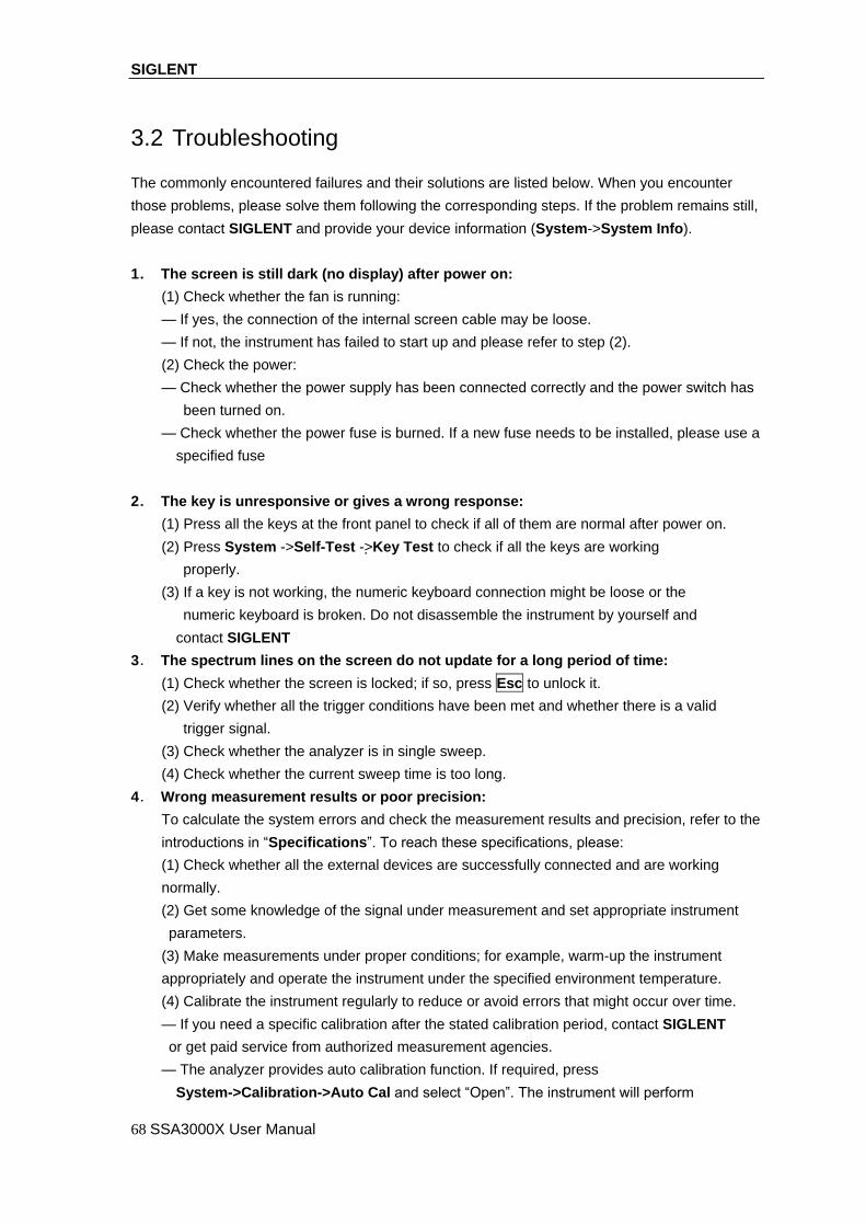
SIGLENT
68 SSA3000X User Manual
3.2 Troubleshooting
The commonly encountered failures and their solutions are listed below. When you encounter
those problems, please solve them following the corresponding steps. If the problem remains still,
please contact SIGLENT and provide your device information (System->System Info).
1. The screen is still dark (no display) after power on:
(1) Check whether the fan is running:
— If yes, the connection of the internal screen cable may be loose.
— If not, the instrument has failed to start up and please refer to step (2).
(2) Check the power:
— Check whether the power supply has been connected correctly and the power switch has
been turned on.
— Check whether the power fuse is burned. If a new fuse needs to be installed, please use a
specified fuse
2. The key is unresponsive or gives a wrong response:
(1) Press all the keys at the front panel to check if all of them are normal after power on.
(2) Press System ->Self-Test ->Key Test to check if all the keys are working
properly.
(3) If a key is not working, the numeric keyboard connection might be loose or the
numeric keyboard is broken. Do not disassemble the instrument by yourself and
contact SIGLENT
3. The spectrum lines on the screen do not update for a long period of time:
(1) Check whether the screen is locked; if so, press Esc to unlock it.
(2) Verify whether all the trigger conditions have been met and whether there is a valid
trigger signal.
(3) Check whether the analyzer is in single sweep.
(4) Check whether the current sweep time is too long.
4. Wrong measurement results or poor precision:
To calculate the system errors and check the measurement results and precision, refer to the
introductions in “Specifications”. To reach these specifications, please:
(1) Check whether all the external devices are successfully connected and are working
normally.
(2) Get some knowledge of the signal under measurement and set appropriate instrument
parameters.
(3) Make measurements under proper conditions; for example, warm-up the instrument
appropriately and operate the instrument under the specified environment temperature.
(4) Calibrate the instrument regularly to reduce or avoid errors that might occur over time.
— If you need a specific calibration after the stated calibration period, contact SIGLENT
or get paid service from authorized measurement agencies.
— The analyzer provides auto calibration function. If required, press
System->Calibration->Auto Cal and select “Open”. The instrument will perform

SIGLENT
SSA3000X User Manual 69
self-calibration regularly.
5. Pop-up Message:
The instrument may display prompt messages, error messages or state messages according
to the current working status. These messages are displayed to help you to use the
instrument correctly and are not instrument failures.

SIGLENT
70 SSA3000X User Manual
Chapter 4 Service and Support
4.1 Maintain Summary
SIGLENT warrants that the products that it manufactures and sells will be free from defects in
materials and workmanship for a period of three years (accessories for a period of one year) from
the date of shipment from an authorized Siglent’s distributor. If the product proves defective within
the respective period, SIGLENT will provide repair or replacement as described in the complete
warranty statement.
To arrange for service or obtain a copy of the complete warranty statement, please contact your
nearest Siglent’s sales and service office. Except as provided in this summary or the applicable
warranty Statement, SIGLENT makes no warranty of any kind, express or implied, including
without limitation the implied warranties of merchantability and fitness for a particular purpose. In
no Event shall SIGLENT be liable for indirect, special or Consequential damages
4.2 Contact Us
SIGLENT TECHNOLOGIES CO., LTD.
Address:3&4/F, building NO.4, Antongda Industrial Zone, 3rd Liuxian Road, Bao’an District,
Shenzhen, P.R.C.
Tel: +86-755-36615186
E-mail:[email protected]
Http://www.siglent.com