contents user manual.pdf · connect nibp extension conduit between the monitor and the patient....
TRANSCRIPT

- V -
Contents
Chapter1Introduction .............................................................................................................................. 1
1.1GeneralInformation ............................................................................................................................. 2
1.2ButtonFunctions .................................................................................................................................. 3
1.3Interfaces ............................................................................................................................................. 4
1.4Accessories .......................................................................................................................................... 4
Chapter2GettingStarted .......................................................................................................................... 6
2.1OpenthePackageandCheck .................................................................................................................. 6
2.2Drybatteryinstallation .......................................................................................................................... 6
2.3PowerontheMonitor ............................................................................................................................. 6
2.4ConnectOximeterProbe ....................................................................................................................... 6
2.5ConnectNIBPCuff ............................................................................................................................... 7
Chapter3FunctionInterface .................................................................................................................... 8
3.1MainInferface ...................................................................................................................................... 8
3.2SystemMenu ........................................................................................................................................ 9
3.2.1SystemSetup ............................................................................................................................. 9
3.2.2BPSETUP .............................................................................................................................. 10
3.2.3SpO2SETUP ........................................................................................................................... 11
3.2.4PatientInformation ................................................................................................................. 11
3.2.5BPTABLE .............................................................................................................................. 12
3.2.6SpO2TABLE .......................................................................................................................... 12
3.2.7DEMOfunction ...................................................................................................................... 13
Chapter4SpO2Monitoring .................................................................................................................... 15
4.1WhatistheSpO2Monitoring ............................................................................................................... 15
4.2PrecautionsduringSpO2/PulseMonitoring ......................................................................................... 15
4.3MonitoringProcedure ........................................................................................................................ 16
4.4MaintenanceandCleaning .................................................................................................................. 16
Chapter5NIBPMonitoring .................................................................................................................... 18
5.1Introduction ....................................................................................................................................... 18
5.2NIBPMonitoring ................................................................................................................................ 18
5.3NIBPMessageandExplanations ......................................................................................................... 19
5.4MaintenanceandCleaning .................................................................................................................. 20
5.5Transportationandstorage .................................................................................................................. 21
5.6KeyofSymbols ................................................................................................................................... 21
Chapter6Installationofthesoftware ....................................................................................................... 23
6.1Demandofeditor ................................................................................................................................. 23
6.2Installationofsoftware ........................................................................................................................ 23
Chapter7Introductiontothesoftware .................................................................................................... 24
7.1Userregister ....................................................................................................................................... 24
7.2Themaininterface ............................................................................................................................... 24
7.3Wear .................................................................................................................................................. 25
7.4Designthemeasurementplan............................................................................................................... 26
7.5Datadownload.................................................................................................................................... 28
7.6Choosepatientdatatoedit .................................................................................................................... 29
7.7Deletedatafile .................................................................................................................................... 30
7.8Datafilebackup .................................................................................................................................. 30

- VI -
7.9EditBloodpressuredata....................................................................................................................... 32
7.10TrendEdit ......................................................................................................................................... 32
7.11Displaythestatisticsinfomation......................................................................................................... 38
7.12Editofdiagnoseinformation. ............................................................................................................. 39
7.13Sleepperiodchange .......................................................................................................................... 40
7.14BPThresholds .................................................................................................................................. 40
7.15Histogram ........................................................................................................................................ 41
7.16Piechart ............................................................................................................................................ 41
7.17Correlationline ................................................................................................................................. 42
7.18Printreport........................................................................................................................................ 43
7.19Help ................................................................................................................................................. 44
Chapter8Troubleshootingguide ............................................................................................................ 45
Appendix ................................................................................................................................................. 46

- 1 -
Chapter1 Introduction
For an overall introduction to the monitor, please refer to General Information.
For basic operating instructions, please refer to Button Function.
For allocation of interface sockets, please refer to Interfaces.
Warning
Possible explosion hazard if used in the presence of flammable anesthetics or other flammable
substance in combination with air, oxygen-enriched environments, or nitrous oxide.
Warning
You must verify if the device and accessories can function safely and normally before use.
Warning
Ensure that the environment in which the device is operated is not subject to any sources of
strong electromagnetic interference, such as radio transmitters, mobile telephones, etc. Keep
them far away High level electromagnetic radiation emitted from such devices may greatly affect the
monitor performance.
Warning
The disposal of scrap instrument and its accessories and packings(including battery, plastic bags,
foams and paper boxes) should follow the local laws and regulations.
Warning
Please choose the accessories and probe which are approved or manufactured by the manufacturer,
or else it may damage the device.
Warning
Dispose of the packaging material, observing the applicable waste control regulations and keeping it
out of children’s reach.
Warning
The monitor is only for use on one patient at a time.
Warning
It is recommended that you check if there is any damage on the monitor or the accessories
regularly,if you find any damage ,stop using it,and contact the biomedical engineer of the hospital or

- 2 -
our CustomerService immediately.
In addition,the overall check of monitor,including the safety check such as the leakage current,should
be performed only by qualified personnel once every 12 months.
Note
Please choose the computer which should be ensured compliance with the requirements of IEC 60950,
or else it may damage the device.
Note
The software was developed per IEC60601-1-4. The possibility of hazards arising from errors in the
software program is minimized.
Caution
At the end of its service life, the product described in this manual, as well as its accessories, must be
disposed of in compliance with the guidelines regulation the disposal of such products. If you have
questions concerning disposal of the product, please contact us or its representatives.
1.1 General Information
Environment:
Temperature
Working 5~40 (C)
Transport and Storage -20~60 (C)
Humidity
Working ≤ 80 %
Transport and Storage ≤ 95 %
Altitude
Working -500 to 4,600m(-1,600 to 15,000ft)
Transport and Storage -500 to 13,100m(-1,600 to 43,000ft)
Power Supply
3 (V)DC
Pmax = 2.56VA
General instruction:
The monitor not only measure the ambulatory blood pressure,but also monitor the parameters of NIBP and
SpO2 .But it is applicable for adult only. It integrates parameter measuring modules funcion and display
function in one device, featuring in compactness, lightweight.
The POWER switch is on the front panel. The RUN indicator and the ALARM indicator flash one time
when the device is powered on. The ALARM indicator flashes when alarm occurs. The sockets of the
sensors are at the top. USB is at the bottom of monitor.
This monitor is a user-friendly device with operations conducted by a few buttons on the front panel. Refer
to Button Functions for details.
Measureing the ambulatory blood pressure function:

- 3 -
In this mode, the monitor can work 24 hours continuously.The monitor have the capable of recording up to
4800 measurements, the stored readings in the monitor are downloaded into the computer to proceed the
function including Editing the data,Editing the trend graph,statistic,displaying the information,Editing the
diagnostic information,setting the parameters and printing and so on.However, this monitor can not
transmit data real-time in the process of measuring.
Monitoring fuction:
NIBP
— From left to right, there are Systolic pressure, Mean pressure and Diastolic pressure(unit:
mmHg or kPa)
SpO2
— SpO2(unit: %)
— Pulse Rate(unit: beats/minute)(When “BOTH” item is selected)
Note
In this mode, the length of working time continuously is decided by the interval of measurement set
by the user.
It is useful that the software at the state of monitoring as the ambulatory blood pressure .
Refer to Software Functions for details.
1.2 Button Functions
All the operations to the monitor are through the buttons at the bottom of the panel. The names of the
buttons are above them. They are:
POWER
Press the button and the system will start.
Note
When the baterry is low, the alarm occurs.
MENU
Whatever levels of menu the system is in, press the button and The system immediately executes a certain
function.
UP
Press the button to select the menu item and modify the setup.
DOWN
Press the button to select the menu item and modify the setup.In the main interface press this button less
than 1second to enter alarm pause status .Press "DOWN" for 1 second to enter the silence status and a
symbol appears at main screen.When the system is in silence status, any newly generated alarm will
discharge the silence status and make the system give normal alarm status. .
Note
Pulse tone will be heard in Silence status, If new alarm occurs in Alarm Silence status, the system will

- 4 -
discharge Silence status automatically, or the silence status will be discharged automatically 1 minute
later .
NIBP
Press to inflate the cuff to start a blood pressure measurement. When measuring, press to cancel the
measurement and deflate the cuff.
Method to use the button to operate in the screen:
The rectangular mark in the screen that moves with the UP button or DOWN button is called “cursor”.
Operation can be performed at any position at which the cursor can stay.
When the item is not to select, the cursor is white; when press MENU to select the item , the cursor become
red.
1.3 Interfaces
For the convenience of operation, the different kinds of interfaces are in different parts of the monitor.
At the top is the Socket for SpO2 Sensor and socket for NIBP cuff(Figure 1--1①)
①the Socket for NIBP cuff
②the Socket for SpO2 Sensor
Figure 1.1 top
At the bottom is the socket for USB, as shown in Figure 1-2.
①the Socket for USB
Figure 1-2 bottom
1.4 Accessories
A a cuff for adult
B a usb data line
C a oximeter probe (Model: SpO2-01-DR)
D a disk (PC software)
② ①
①

- 5 -
E a pouch
F a user manual
Warning
Please use the accessories supplied by the manufacturer or replace the accessories according to the
requirements of the manufacturer in order to avoid making harms to patients.

- 6 -
Chapter 2 Getting Started
■ Open the package and check
■ Dry battery installation
■ Power on the monitor
■ Connect patient sensors
2.1 Open the Package and Check
Open the package and take out the monitor and accessories carefully. Keep the package for possible future
transportation or storage. Check the components according to the packing list.
■ Check for any mechanical damage.
■ Check all the cables, modules and accessories.
If there is any problem, contact the distributor immediately.
2.2 Dry battery installation
The monitor will be supplied with two 'AA' alkaline batteries or high capacity.Before using the monitor you
shall put the battery in the box of battery .
Note
When you don't use the monitor , you will take out the dry battery.
2.3 Power on the Monitor
Press POWER to power on the monitor. The indicator will flash, the system will enter monitoring screen
of monitoring or ABPM, and you can perform normal monitoring now. Refer to System Menu for details.
Warning
If any sign of damage is detected, or the monitor displays some error messages, do not use it on any
patient. Contact biomedical engineer in the hospital or our Customer Service Center immediately.
Note
Check all the functions that may be used to monitor and make sure that the monitor is in good status.
2.4 Connect Oximeter Probe
Note
For information on correct connection, refer to figure 2.4.1.
Figure 2.4.1

- 7 -
2.5 Connect NIBP Cuff
Connect NIBP extension conduit between the monitor and the patient.
Note
For information on correct connection, refer to figure 2.5.1.
Figure 2.5.1

- 8 -
Chapter3 Function Interface
■ Main Interface
■ System Menu
3.1 Main Inferface
Press POWER to power on the monitor,The indicator will flash, the system will enter the main interface
successfully.
ABPM : If there is no key-press operation within the time set in the BACKLIGHT TIME item, the monitor
will enter standby mode.RUN indicatorlight flashes once every other 2 seconds, indicating the monitor is
under working mode.
Monitoring Mode: BACKLIGHT TIME item setup is of no effect. The backlight is bright all the time.
The '04' will be displayed in the middle of the speaker and battery When the power is low.
The main interface is shown as the follow:
Figure 3.-1.1 ABPM main menu
Figure 3.1.-2 MONITORING main menu

- 9 -
Note
When the register is full, will be appearanced at the top of screen. The note of the last value needs
to be cleared.
3.2 System Menu
Press the MENU button on the panel to call up the [SYSTEM MENU]. You can perform option operations
by using UP and DOWN buttons.
Figure 3.2 SYSTEM MENU
[PM BP SETUP], [PM SpO2 SETUP] and [SpO2 TABLE] are gray in the mode of ABPM. They can not
be set up.
3.2.1 System Setup
Select the SYSTEM SETUP item in the [SYSTEM MENU]. The following menu will pop up.
Figure 3.2.1 SYSTEM SETUP
Users can set up the system time by selecting the [TIME] item.
If users select [YES] in the [DEFAULT] item, the Monitor will come back to factory default.

- 10 -
In the [LANGUAGE] item, users can select the words shown in Chinese or English in the screen.
If users select [ON] in the [ALARM] item, the loudspeaker turns on. will be appeared in the main
monitoring interface. On the other hand, when users select [OFF], the loudspeaker turns off, will
turns up.
In the [NEW PATIENT] item, if users select [OFF], the "Clear the last value? “dialog box will appear.
Select [YES] again will delete the measure record of the last patient, then select [NO] back to the
[SYSTEM SETUP MENU]. Else, selecting [NO] at first, the monitor will do nothing. Please pay attention
to this function.
Users can select PM or ABPM in the [FUNCTION SELECT] item and correspond measures will be taken.
In the [BACKLIGHT TIME] item, users can make it from 5 to 120 seconds with 5 seconds per step. Its
funtion is to control the backlight time of the main interface in ABPM.
Under the ABPM, [DEFAULT], [ALARM] and [NEW PATIENT] can not be set up.
3.2.2 BP SETUP
Select [PM BP SETUP] in the[ "SYSTEM MENU"]. The following menu will pop up.
Figure 3.2.2 BP SETUP
When users select [ON] in the [AUTO MEASURE] item, the Monitor will measure blood pressure
according to the time selected in the [INTERVAL] item. When [OFF] is selected, manual measure is
needed,simultaneously [INTERVAL] item turns gray and can not be set up.
The interval time (Uint: minute) setup in the [INTERVAL] item can be selected from the following options:
5, 10, 15, 20, 30, 45, 60, 90.
The alarm is on or off according to the high and low limits which have been set up. When the pressure
higher than the high limit or lower than the low limit, the alarm will occur. [SYS ALM], [MEAN ALM]
and [DIA ALM] can be processed separately.
The adjustable ranges of the high and low limits of the alarm are as follows:
DIA ALM: 40~270 mmHg
SYS ALM: 10~215 mmHg
MEAN ALM: 20~235 mmHg

- 11 -
3.2.3 SpO2 SETUP
Select [PM SpO2 SETUP] in the "SYSTEM MENU". The following menu will pop up.
Figure 3.2.3 SpO2 SETUP
For the [PULSE SOUND] item,you can choose its state.When it is “ON”, pulse sound plays while the
monitor measure the ambulatory blood pressure.When it is “OFF”, pulse sound dosen't play while the
monitor measure the ambulatory blood pressure.
For the [SpO2 ALM HI/LO] item, you can set up [SpO2 ALM H] and [SpO2 ALM LO].Alarm occurs,when
SpO2 value overflows .
For the [PR ALM HI/LO] item, you can set up [PRALM HI] and [SpO2 ALM LO].Alarm occurs,when PR
value overflows.
SpO2 and PR ALARM analysis alarm limits:
3.2.
4
Patient Information
Pick the [ABPM INF0] item in the “SYSTEM MENU” to call up the following menu.
Figure 3.2.4 ABPM INFOR
PARAMETERS Max. HI Min. LO Step
SpO2 100 0 1
PR 254 0 1

- 12 -
The information in this interface can't be changed,until reinstall the parameter in software.
3.2.5 BP TABLE
Pick the [BP TABLE] item in the “SYSTEM MENU” to call up the following menu.
Figure 3.2.5.1 NIBP TABLE
[total]: the number is the total of all data have been measured from accessing this interface the first
time.The sequence number of the current first line will be displayed when changing the data or turning over
pages. Every page can contain 10 data at most.
Select the [change] item to enter the [Change The Number] menu:
Figure 3.2.5.2 CHANGE
When the number which you input is more than the total,it will prompt ">total". Blood preasuremeasure
one time per 5 minutes,and the most number of times is 4896.
3.2.6 SpO2 TABLE
Pick the [SpO2 TABLE] item in the “SYSTEM MENU” to call up the following menu.

- 13 -
Figure 3.2.6.1 SpO2 TABLE
[total]: the number is the total of all data have been measured,while accessing this interface for the first
time.The sequence number of the first line currently will be displayed,while changing the data or turning
over page.Every page can contain 10 data at most.
Select the [change] item to enter the [Change The Number] menu:
Figure 3.2.6.2 CHANGE
When the number which you input is more than the total,it will prompt ">total".The blood preasure is
measured once per 1 s,and the most number of times is 183000.
3.2.7 DEMO function
Select the [DEMO] item to enter DEMO status.In the DEMO status, press the “MENU KEY”,and system
returns to the "MAIN MENU".

- 14 -
Figure 3.2.7 DEMO
Note
In clinical application, this function is forbidden because the DEMO will mislead the medical staff to
treat the DEMO waveform and parameter as the actual data of the patient, which may result in the
delay of treatment or mistreatment.
When it is ambulatory blood pressure state,[PM BP SETUP]、[PM SpO2 SETUP] and [SpO2 TABLE] can't
be changed in the "MAIN MENU".

- 15 -
Chapter 4 SpO2 Monitoring
4.1 What is the SpO2 Monitoring
SpO2 Plethysmogram measurement is employed to determine the oxygen saturation of hemoglobin in the
arterial blood. If, for example, 97% hemoglobin molecules in the red blood cells of the arterial blood
combine with oxygen, then the blood has a SpO2 oxygen saturation of 97%. The SpO2 numeric on the
monitor will read 97% .The SpO2 numeric shows the percentage of hemoglobin molecules which have
combined with oxygen molecules to form oxyhemoglobin. The SpO2/PLETH parameter can also provide a
pulse rate signal and a plethysmogram wave.
How the SpO2 / PLETH Parameter Works
■ Arterial oxygen saturation is measured by a method called pulse oximeter. It is a continuous,
non-invasive method based on the different absorption spectra of reduced hemoglobin and
oxyhemoglobin. It measures how much light, sent from light sources on one side of the sensor, is
transmitted through patient tissue (such as a finger or an ear), to a receiver on the other side.
The sensor measurement wavelengths are nominally 660nm for the Red LED and 940nm for Infrared
LED. Maximum optical power output for LED is 4 mW.
■ The amount of light transmitted depends on many factors, most of which are constant. However, one
of these factors, the blood flow in the arteries, varies with time, because it is pulsating. By measuring
the light absorption during a pulsation, it is possible to derive the oxygen saturation of the arterial
blood. Detecting the pulsation gives a PLETH waveform and pulse rate signal.
■ The SpO2 value and the PLETH waveform can be displayed in the main screen.
Warning
ES (Electrosurgery) equipment wire and SpO2 cable must not be tangled up.
Warning
Do not put the sensor on extremities with arterial catheter or venous syringe.
Note
Do not perform SpO2 measuring and NIBP measuring on same arm at one time, because obstruction
of blood flow during NIBP measuring may adversely affect the reading of SpO2 value.
4.2 Precautions during SpO2/Pulse Monitoring
Note
■ Make sure the nail covers the light window;
■ The wire should be on the backside of the hand.
Note
SpO2 waveform is not proportional to the pulse volume.

- 16 -
Warning
Do not use the SpO2 sensor once the package or the sensor is found damaged. Instead, you shall
return it to the vendor.
Warning
Prolonged and continuous monitoring may increase jeopardy of unexpected change of dermal
condition such as abnormal sensitivity, rubescence, vesicle, repressive putrescence, and so on. It is
especially important to check the sensor placement of neonate and patient of poor perfusion or
immature dermogram by light collimation and proper attaching strictly according to changes of the
skin. Check per 2~3 hours the sensor placement and move it when the skin deteriorates. More
frequent examinations may be required for different patients.
4.3 Monitoring Procedure
SpO2 plethysmogram measurement
1. Switch on the monitor.
2. Attach the sensor to the appropriate site of the patient finger.
3. Plug the connector of the sensor extension cable into the SpO2 socket ,please pay attention to the
direction of the sensor.
4. Please pull out the sensor When measure is over.
Figure 4.3 Mounting of the sensor
4.4 Maintenance and Cleaning
Care and Cleaning
Warning
Turn off the monitor before cleaning the monitor or the sensor
Warning
Do not subject the sensor to autoclaving.
Do not immerse the sensor into any liquid.
Do not use any sensor or cable that may be damaged or deteriorated.

- 17 -
Cleaning:
Use a cotton ball or a soft mull moistened with hospital-grade ethanol to wipe the surface of the sensor,
and then dry it with a cloth. This cleaning method can also be applied to the luminotron and receiving
unit.
The cable can be cleaned with 3% hydrogen dioxide, 70% isopropanol, or other active reagent.
However, connector of the sensor shall not be subjected to such solution.

- 18 -
Chapter 5 NIBP Monitoring
5.1 Introduction
■ The Non-invasive Blood Pressure (NIBP) module measures the blood pressure using the oscillometric
method.
■ There are two modes of measurement available: manual and automatic . Each mode displays the
diastolic, systolic and mean blood pressure.
In the MANUAL mode, only one measurement is conducted for each time.
In the AUTO mode, the measurement is cycled; you can set the interval time to
5/10/15/20/30/45/60/90 minutes.
Warning
Prolonged non-invasive blood pressure measurements in Auto mode may be associated with purport,
ischemia and neuropathy in the limb wearing the cuff. When monitoring a patient, examine the
extremities of the limb frequently for normal color, warmth and sensitivity. If any abnormality is
observed, stop the blood pressure measurements.
Warning
1. You must not perform NIBP measurements on patients with sickle-cell disease or under any
condition which the skin is damaged or expected to be damaged.
2. For a thrombasthemia patient, it is important to determine whether measurement of the blood
pressure shall be done automatically. The determination should be based on the clinical evaluation.
5.2 NIBP Monitoring
Warning
Do not apply the cuff to a limb that has an intravenous infusion or catheter in place. This could cause
tissue damage around the catheter when infusion is slowed or blocked during cuff inflation.
Warning
Make sure that the air conduit connecting the blood pressure cuff and the monitor is neither blocked
nor tangled.
1. Plug in the air hose and switch on the system.
2. Apply the blood pressure cuff to the patient's arm or leg following the instructions below (Figure 5.2).
■ Ensure that the cuff is completely deflated.
■ Apply the appropriate size cuff to the patient, and make sure that the symbol "Φ" is over the
appropriate artery. Ensure that the cuff is not wrapped too tightly around the limb. Excessive tightness
may cause discoloration and eventual ischemia of the extremities.

- 19 -
Figure 5-.2 Applying Cuff
Note
Don't let the cuff contact with skin directly, but the thickness of clothes shoudn't be more than
3 cm.
Note
The width of the cuff should be either 40% of the limb circumference (50% for neonates) or 2/3 of
the upper arm length. The inflatable part of the cuff should be long enough to encircle 50-80% of the
limb. The wrong size of cuff can cause erroneous readings. If the cuff size is in question, then use a
larger cuff.
Size of reusable cuff for neonate/children/adult
Patient Type Limb perimeter Cuff width Hose
Adult 25 ~ 35 cm 14 cm 1.5 m or
3 m Large Adult 33 ~ 47 cm 17 cm
Thigh 46 ~ 66 cm 21 cm
■ Make sure that the cuff edge falls within the range of mark <->. If it does not, use a larger or smaller
cuff that fits better.
3. Connect the cuff to the air hose. The limb chosen for taking the measurement should be placed at the
same level as the patient's heart. If this is not possible you should apply the following corrections to
the measured values:
■ If the cuff is placed higher than the heart level, add 0.75 mmHg (0.10 kPa) for each inch of difference.
■ If it is placed lower than the heart level, deduct 0.75 mmHg (0.10 kPa) for each inch of difference.
4. Press the NIBP button on the front panel to start a measurement.
5.3 NIBP Message and Explanations
Messa
ge
Explanation Cause
02 Self-test failure
Probe or A/D sampling error.
06 Loose cuff
Cuff is not connected correctly.
07 Air leakage Air leakage in the valve or airway.
08 Atmospheric pressure error
Valve can not be open.
09 Signal is too weak Object measuring the pulse is too weak or the cuff is

- 20 -
loose.
10 It is over the range Object measuring blood pressure is over the measurement
range.
11 Excessive movement When measuring, signal the presence of excessive
movement or pseudo-differential interference.
12 Overpressure Cuff pressure is over the scope ,ADU 290 mmHg
13 Saturated signal Movement or other factors lead to too big signal
amplitude.
14 Air leakage There is air leakage in the airway
15 System failure There is something wrong with NIBP module ,A/D
sampling or soft of system after turning on the device.
19 It spends too much time Measuring is over certain specified time
.When pressure of adult cuff is 200mmHg,it may spend
120s.If not, it may spend 90s.
5.4 Maintenance and Cleaning
Warning
■ Do not squeeze the rubber tube on the cuff.
■ Do not allow liquid to enter the connector socket at the front of the monitor.
■ Do not wipe the inner part of the connector socket when cleaning the monitor.
Reusable Blood Pressure Cuff
The cuff can be sterilized by means of conventional autoclaving, gas, or radiation sterilization in hot air
ovens or disinfected by immersion in decontamination solutions, but remember to remove the rubber bag if
you use this method. The cuff should not be dry-cleaned.
The cuff can also be machine-washed or hand-washed, the latter method may prolong the service life of the
cuff. Before washing, remove the latex rubber bag, and for machine-washing, close the Velcro fastening.
Allow the cuff to dry thoroughly after washing, then reinsert the rubber bag.

- 21 -
Figure 5.3 Replace Rubber Bag in Cuff
To replace the rubber bag in the cuff, first place the bag on top of the cuff so that the rubber tubes line up
with the large opening on the long side of the cuff. Now roll the bag lengthwise and insert it into the
opening on the long side of the cuff. Hold the tubes and the cuff and shake the complete cuff until the bag is
in position. Thread the rubber tubes from inside the cuff, and out through the small hole under the internal
flap.
Disposable Blood Pressure Cuffs
Disposable cuffs are intended for one-patient use only. Do not use the same cuff on any other patient. Do
not sterilize or use autoclave on disposable cuffs. Disposable cuffs can be cleaned using soap solution to
prevent infection.
Note
For protecting environment, the disposable blood pressure cuffs must be recycled or disposed
properly.
5.5 Transportation and storage
A. The packed device can be transported by ordinary conveyance or according to transport contract.The
device can not be transported mixed with toxic, harmful, corrosive material.
B. The packed device should be stored in room with no corrosive gases and good ventilation. Temperature:
-20°C~60°C; Humidity: ≤95%
5.6 Key of Symbols
Signal Description
Warning – See User Manual
SYS Systolic pressure
MEAN MEAN pressure
DIA Diastolic pressure

- 22 -
The pulse oxygen saturation(%)
Pulse rate (bpm)
Close the sound
Open the alarm sound indication
Close the alarm sound indication
Type BF
SN Serial number
1. the finger clip falls off ( no finger inserted)]
2. Probe error
3. Signal inadequacy indicator
IPX1 Ingress of liquids rank

- 23 -
Chapter 6 Installation of the software
Demand of editor
Installation of software
6.1 Demand of editor
Processor: Pentium IV 1.8G or more
Operation System:XP
EMS memory: 256M and up
Hard Disk: 40G or more
Display: 17 inch or more
CD-ROM
Serial port
Resolution of printer: 600 DPI
6.2 Installation of software
1 Place the CD-ROM in the CD-ROM compartment located on your computer.
2 If Auto Play for CDs is enabled, place CD in reader and follow instructions when they appear in the
screen; otherwise follow install instructions below:
Open Windows Explorer.
Click on the root CD-ROM directory.
Double click file PM50_Patient_Monitor_V1.1_Setup.exe.
Follow the instructions in the screen.

- 24 -
Chapter 7 Introduction to the software
7 .1 User register
Each time you open the software will appear the following dialog box for the user's name. Type in user's
name. To change user go to "File" then click on "Change User". This feature is available to allow each user
to store his or her own configurations, such as thresholds.
Figure 7.1.1 User Register
Click "Delete" button will delete the current selected user info and configuration. Click "Delete
all" Button will delete all users info and their configurations.
If you are a new user, click "Okay" Button will appear the following dialog box.
Figure 7.1.2 Set file path
"Patient File Path": Choose the downloading route of your case. As soon as the data are downloaded in
computer, the case document will save this path.
If you check the "Always use default path" checkbox, then data searches will always begin at the default
path. If the checkbox is not checked, then data searches will always begin at the last path used.
7 .2 The main interface
When the settings of the user’s configuration information are finished, the main interface is

- 25 -
entered, as the following pictured displayed:
Figure 7.2 the main operating interface
1. Menu bar The main operating menu of this software
2. Toolbar Shortcut keys for functions of frequent use
3. Displaying areas of the trending pictures
After choosing the case which is edited, it is used for displaying date of the trending picture.
4. Status bar Display the name, ID, and the data collecting date of the patient.
7.3 Wear
Press the shortcut key ,will pop up the following dialog box.
①
②
③
④

- 26 -
Figure 7.3 Wear
You can wear the device accroding to the picture above. Please read the "Note" Carefully before use.
7.4 Design the measurement plan
Note : Before you upload the test parameters to the device , make certain:
1. The device is connected to the computer via the serial port.
2. The device is turned on.
Steps:
1. Press the shortcut key , or from the menu select "Upload" ,the following dialoga box will
appear .
Figure 7.4.1 Select the status of the device

- 27 -
2. If the item you choosed is "ABPM" the following dialog box will appear.
Figure 7.4.2 Upload test parameters
Patient Name, Patient ID : mark the patient.
Current Time: That is the time of beginning to collect the parameter.
Study Start Time: Collecting start time. It defaulted in the 5 minutes after setting the collecting parameter.
Start key : Whether supporting the manual collecting.
Time Periods:
Among that, Awake refers to the patient in the un-sleeping situation, and Asleep refers to the sleeping
situation.
Special Start and Special End are optional items.
You can set the fixed time to collect the data. Interval setting refers to the intervals of the collecting time.
To reduce the impact of the patient’s sleep, settings of the general collecting intervals are longer.
Take the above picture as an example: the range of un-sleeping time is 7:00-22:00, the range of sleeping
time is 22:00-7:00, the intervals of the un-sleeping time are 5 minutes, and the intervals of the sleeping time
are 30 minutes.
The range of sleeping time, the range of un-sleeping time, the range special testing time are displayed by
the picture forms in the right corner of the screen. Thus, it is convenient to design the parameter.

- 28 -
If the item you choosed is "Patient Monitor" the following dialog box will appear.
Figure 7.4.3 Upload test parameters
3. Select the "OK" button will appear the following dialog box show the progress as the data is transferred.
Figure 7.4.4 Uploading progress bar
7.5 Data download
Before you download the measurement data from device , make certain:
1. The device is connected to the computer via the serial port.
2. The device is turned on.
3. Disconnect the device from patient before you connecting it to any piece of hardware such as your personal
computer (to avoid electric shock)
The downloaded patient data will be saved in your default computer path. If you want to change
the storage path, from the menu select "Download" and the select "Set file path", and then the dialogue
box(Figure 7.1.2) referred before will be showed up, operators can change the path.
Press the shortcut key , or from the menu select "Download" and then select "Do Download"
will appear the following dialog box .Permiting you select what data you want to download(ABPM data or
Patient Monitor data ).

- 29 -
Figure 7.5.1 Select the status of the device
The following dialog box will appear to show the progress as the data is transferred.
Figure 7.5.2 Downloading progress bar
After completion, a dialog box will prompt for where the data file was saved.
7.6 Choose patient data to edit
Press shortcut key , or from the menu select "File" and select "Open data" the following dialog
box will appear:
Figure 7.6 Patient file select

- 30 -
The above dialog box lists the data files found in your current directory. You may use the drive and
directory boxes to select a different drive or directory to search for patient files. Select a data file by
highlighting the patient's name, and then press the "Okay" button. You may now edit the data.
7.7 Delete data file
If you feel some patient data are not necessary, you can delete them. From menu select "File" and
then select "Delete Data" to show patient data delete interface which is similar to patient data select
interface, showed as below:
Figure7.7 Data file delete
You are able to delete one single file or some files at the same time, to delete some files at the
same time; you could push “Ctrl”, and click the file you want to delete at the same time. After
selection, click "Okay" button,the "sure to delete " Dialog will appear . Click " YES" to complete the
delete operation . If you want to cancel, please click "NO".
7.8 Data file backup
Sometimes, you may want to save one original copy before you edit a file, under this situation, you
should do patient data backup.
From the menu select "File" and then select "Copy data", will appear the following dialog box,
permiting you to select which data files to copy.

- 31 -
Figure7.8.1 Data file copy
Select or deselect items by clicking on the rows using the mouse.When all desired selections have been
made , select "Okay".
The following dialog box will appear, permiting you to select the disk drive or directoy to copy to.
Figure 7.8.2 Backup path settings
Once you have selected the destination drive or directory , select "Okay".You may also select "Cancel" to end
the dialog without copying patient data.

- 32 -
7 .9 Edit Blood pressure data
Press the shortcut key , or from the menu select "Edit" and then select "Bp Data" the following
dialog box will pop up.
Figure 7.9 Data edit page
All the BP readings are shown in the above dialog box.
*=6/60(10.0%): 60 represents the total data sum, 6 represents the data amount deleted, 10.0% stands for data
present deleted.
Number: stands for data collection serial number.
Time: stands for collection time.
Date: stands for collection date.
BP: number before "/" stands for high blood pressure, number back "/" stands for low blood pressure.
HR: Heart rate.
MAP: Mean pressure.
PP: Pressure difference between high and low blood pressure.
TC: error code(refer to chapter 9 )
Comment: comment.
7.10 Trend Edit
BP Trend Edit
When you selected the data file, the BP trend will be shown in the screen automatically.In other

- 33 -
interfaces you can press shortcut key enter the "BP trend" interface.The "Bp Trend" has two
garph types:color filler type, dotted line type.You can switch from one graph type to another by push
the "Graph Type" button.
Figure 7.10.1 Color filler type BP trend

- 34 -
Figure 7.10.2 Dotted line type BP trend
When you move the mouse on the trend area, on the top of the trend area the detail data
information about the mouse points will show, including the data serial number, collection time and
collection date, high/low blood pressure value, heart rate, comment, etc. Press mouse’ left button to
delete or add the data point to be shown.
If the distance between the two data points is too short to move the mouse to one of the points,
move the mouse to the time axis area, press the mouse’ left button down, dragging the mouse to the
right stretch the BP Trend. Of course you can also dragging the mouse to the left shrink the BP Trend.
When you stretching the BP Trend, if the trend length beyond the trend show area will appear a
horizontial scroll bar, you can see any part of the trend by changing the scroll bar's pos.
Move the mouse to the y-axis area, press the mouse’ left button down, dragging the mouse to the
top stretch the BP Trend. Of course you can also dragging the mouse to the bottom shrink the BP
Trend.

- 35 -
Figure7.10.3 Stretch BP Trend(time axis)
Figure7.10.4 Shrink BP Trend(time axis)

- 36 -
Figure7.10.5 Stretch BP Trend(y-axis)
Figure7.10.6 Shrink BP Trend(y-axis)
SpO2 Trend Edit

- 37 -
press the short cut key, will appear the SpO2 trend interface.
Figure 7.10.7 SpO2 Trend
The following picture show different parts of the data area.
Move the mouse in the data area, you will see a yellow line, and on top of the data area is the
"Selected data info", where you will see the exact SpO2 and pulse value according to the time. Along with
the mouse move, the value will change accordingly.
The SpO2 and pulse ruler lines show the exact value of the horizontal lines. You can reset these lines by
keeping the mouse right button clicked on the "SpO2 ruler" area or "Pulse ruler" area, and move the mouse.
This 4 buttons are used to set the page length, that is how long data will be
visible at the same time in the window area from left to right.
"1": 1 minute. "10": 10 minute. "60": one hour. : manual set, click this button will pop up a
dialog box, and you can set the length you want.
This 4 buttons are used to move the data offset, that is what time is at the left
of the window.
"<<" and ">>" buttons move the offset back or forth by page length. If you select "1" as the page
length, ">>"will move data time forward by 1 hour.
"<" and ">" buttons move the offset back or forth by step length. Step length is smaller than page size,

- 38 -
1 page often contains several steps, the steps are marked in the time area, and the time mark is marked each
step length.
Click the "Parameters set" button will appear the following dialog box.
Figure 7.10.8 Analysis parameters settings
The setup in the dialog box above indicates:
SpO2(desaturation)event: the SpO2 value reduces at least 4% while the time keeps at least 10 seconds.
Pulse Rate event: the pulse rate fluctuates at least 6bpm while the time keeps at least 8 seconds.
7.11 Display the statistics infomation
Press the shortcut key , or from the menu select "Report" and the select "View Statistics" will
pop-up the following dialog box.

- 39 -
Figure 7.11 BP statistics information
7.12 Edit of diagnose information.
Diagnose information including following items: Patient information, Interpretation, Current
Medication and Physician information.
From the menu select "Edit" and then select "Patient Data" will pop up the following dialog box.
Figure7.12.1 Edit patient’s information

- 40 -
click "Current Medications" switch to Current Medications interface, then you can modify the
medications for the patient.
click "Interpretation" switch to Interpretation interface.
click "Physician Info" switch to the page of doctor's advice.
7 .13 Sleep period change
Sleep period includes: Awake time and asleep time. Because when collecting patient parameter,
patient not always fall asleep and awake according to collection data protocol strictly, you may need
change your sleep period . After setup of sleep period, the software will calculate the data
automatically, update the BP Trend and recalculate the statistic data.
Figure 7.13 Sleep period dialog box
7.14 BP Thresholds
After BP Thresholds being set up, the trend graph will renew automaticly, statistic data will be
recalculated.
From the view select "Edit" and then select "Thresholds" will appear the following dialog box.
Figure 7.14 thesholds dialog box
The default, recommended thresholds for calculating Blood Pressure Load are 140/90 for awke
- 41 -
periods and 120/80 for sleep periods. These are the defaults used when you select the Factory Defaults
button.
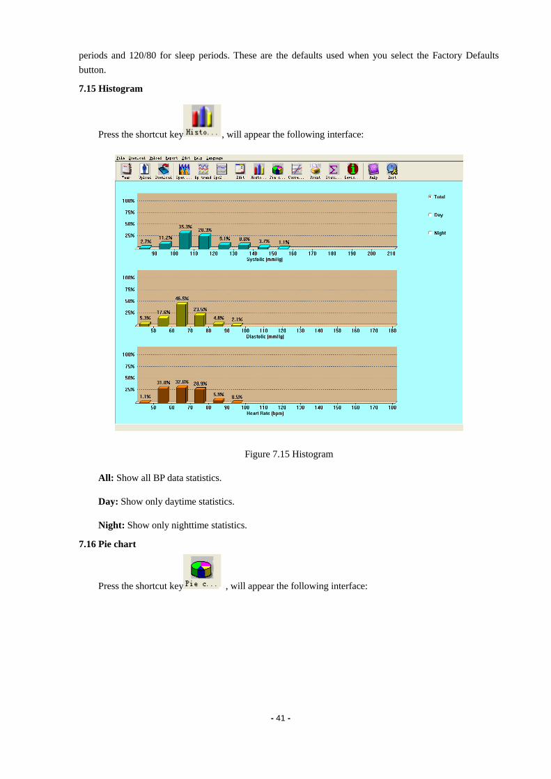
7.15 Histogram
Press the shortcut key , will appear the following interface:
Figure 7.15 Histogram
All: Show all BP data statistics.
Day: Show only daytime statistics.
Night: Show only nighttime statistics.
7.16 Pie chart
Press the shortcut key , will appear the following interface:

- 42 -
Figure 7.16 Pie chart
You can adjust to show the percentage of above normal value, normal value and below normal value.
On the left, some statistics can be displayed, such as BP value, HR maximum, minimum, and average
value,etc.
All: Show all BP data statistics.
Day: Show only daytime statistics.
Night: Show only nighttime statistics.
7.17 Correlation line
Press the shortcut key , will appear the following interface:

- 43 -
Figure 7.17 Correlation line
Red line represents systolic; blue line represents diastolic.White small circle represents day time BP
value; black small circle represents night time BP value.
Histogram、Pie chart and Correlation line are usefull for your observation about the data.
7.18 Print report
After previous data edit, diagnose information edit, trend edit, and so on, the software will create
a series of diagnose reports, you can select these pages or some of them for printing. The information
of your selection can be saved as default print page for next time.
From menu select "Report" and then select "Configure Report" Will appear the following dialog
box:
Figure 7.18.1 Configure Report
You can select an already exist report for print, you may also click "Edit Report" edit the selected
report.

- 44 -
Figure 7.18.2 Edit Report
You can select all pages or some of them for printing. Only when the data file include SpO2 data and
you checked the "SpO2 Report" could print SpO2 report.
Click "Title" button, you may enter the title to print at the top of the printed report.
Of course you can also click "Add Report" add a new report. If you don't need the current report, you
can also click "Delete Report" to delete it.
The default paper size is: A4, from the menu select "Report" and then select "Select printer", you can
select a printer. From the menu select "Report" and then select "Print preview", you can preview the page
you selected.
When you sure you want to print the reprot, press shortcut key , or from menu select
"Report" and then select "Print".
7.19 Help
Press shortcut key will pop up help document.Meanwhile, you will find in
operation interface; click this button can also active the help document.

- 45 -
Chapter 8 Troubleshooting guide
Code Descripti on in Report Editor Solution
1 No signal Check position of cuff, tighten cuff
2 Overreach movement Remain still during BP reading
4 Measurement timeout Check air hose connections and make
certain cuff is tight
85 Airway obstructed Check air hose connections and make
certain air tubing is not crimped.
86 Measurement cancelled Push START/STOP button to start
reading.
87 Cuff leak Check air hose and cuff
88 safety time-out
Retry reading, push START/STOP
button. If problem persists return
monitor for servicing.
89 cuff overpressure Check for blocked or kinked air hose.
90 Battery low Replace batteries. If problem persists
return for servicing.
102 Self-check failed Return for servicing.
110 Out of range Retry again, if problen persists return for
servicing.
115 System error Return for servicing.

- 46 -
Appendix
Guidance and manufacture’s declaration-electromagnetic emission
for all EQUIPMENT and SYSTEMS
Guidance and manufacture’s declaration – electromagnetic emission
The PM50 Patient Monitor is intended for use in the electromagnetic environment specified below. The
customer of the user of the PM50 Patient Monitor should assure that it is used in such and environment.
Emission test Compliance Electromagnetic environment – guidance
RF emissions
CISPR 11 Group 1
The PM50 Patient Monitor uses RF energy only for
its internal function. Therefore, its RF emissions are
very low and are not likely to cause any interference in
nearby electronic equipment.
RF emission
CISPR 11 Class B
The PM50 Patient Monitor is suitable for use in all
establishments, including domestic establishments and
those directly connected to the public low-voltage
power supply network that supplies buildings used for
domestic purposes.
Harmonic emissions
IEC 61000-3-2 Not applicable
Voltage fluctuations/
flicker emissions
IEC 61000-3-3
Not applicable
Guidance and manufacture’s declaration – electromagnetic immunity
for all EQUIPMENT and SYSTEMS
Guidance and manufacture’s declaration – electromagnetic immunity
The PM50 Patient Monitor is intended for use in the electromagnetic environment specified below. The
customer or the user of PM50 Patient Monitor should assure that it is used in such an environment.
Immunity test IEC 60601 test level Compliance level Electromagnetic environment -
guidance
Electrostatic
discharge (ESD)
IEC 61000-4-2
6 kV contact
8 kV air
6 kV contact
8 kV air
Floors should be wood, concrete or
ceramic tile. If floor are covered
with synthetic material, the relative
humidity should be at least 30%.
the manufacturer may recommend
the ESD precautionary procedures
to user.
Power frequency
(50Hz) magnetic field
IEC 61000-4-8
3A/m 3A/m Power frequency magnetic fields
should be at levels characteristic of
a typical location in a typical
commercial or hospital
environment.

- 47 -
Guidance and manufacture’s declaration – electromagnetic immunity
for EQUIPMENT and SYSTEMS that are not LIFE-SUPPORTING
Guidance and manufacture’s declaration – electromagnetic immunity
The PM50 Patient Monitor is intended for use in the electromagnetic environment specified below. The
customer or the user of PM50 Patient Monitor should assure that it is used in such an environment.
Immunity test IEC 60601 test level Compliance
level Electromagnetic environment - guidance
Conducted RF
IEC 61000-4-6
Radiated RF
IEC 61000-4-3
3 Vrms
150 kHz to 80 MHz
3 V/m
80 MHz to 2.5 GHz
3 Vrms
3 V/m
Portable and mobile RF communications
equipment should be used no closer to any part of
the PM50 Patient Monitor, including cables, than
the recommended separation distance calculated
from the equation applicable to the frequency of
the transmitter. Recommended separation distance
PE
d
1
5.3 80 MHz to 800 MHz
PE
d
1
7 800 MHz to 2.5 GHz
Where P is the maximum output power rating of
the transmitter in watts (W) according to the
transmitter manufacturer and d is the
recommended separation distance in metres (m).
Field strengths from fixed RF transmitters, as
determined by an electromagnetic site survey,a
should be less than the compliance level in each
frequency range.b
Interference may occur in the vicinity of
equipment marked with the following symbol:
NOTE 1 At 80 MHz and 800 MHz, the higher frequency range applies.
NOTE 2 These guidelines may not apply in all situations. Electromagnetic propagation is affected by absorption
and reflection from structures, objects and people. a Field strengths from fixed transmitters, such as base stations for radio (cellular/cordless) telephones and land
mobile radios, amateur radio, AM and FM radio broadcast and TV broadcast cannot be predicted
theoretically with accuracy. To assess the electromagnetic environment due to fixed RF transmitters, an
electromagnetic site survey should be considered. If the measured field strength in the location in which the PM50 Patient Monitor is used exceeds the applicable RF compliance level above, the PM50 Patient Monitor should be observed to verify normal operation. If abnormal performance is observed, additional
measures may be necessary, such as reorienting or relocating the PM50 Patient Monitor. b Over the frequency range 150 kHz to 80 MHz, field strengths should be less than 3 V/m.

- 48 -
Recommended separation distances between portable and mobile
RF communications equipment and the EQUIPMENT or SYSTEM –
for EQUIPMENT or SYSTEM that are not LIFE-SUPPORTING
Recommended separation distances between
portable and mobile RF communications equipment and the PM50 Patient Monitor
The PM50 Patient Monitor is intended for use in an electromagnetic environment in which radiated RF
disturbances are controlled. The customer or the user of the PM50 Patient Monitor can help prevent
electromagnetic interference by maintaining a minimum distance between portable and mobile RF
communications equipment (transmitters) and the PM50 Patient Monitor as recommended below, according to
the maximum output power of the communications equipment.
Rated maximum output
power of transmitter
(W)
Separation distance according to frequency of transmitter
(m)
150 kHz to 80 MHz
PV
d
1
5.3
80 MHz to 800 MHz
PE
d
1
5.3
800 MHz to 2.5 GHz
PE
d
1
7
0.01 0.117 0.117 0.233
0.1 0.369 0.369 0.738
1 1.167 1.167 2.333
10 3.689 3.689 7.379
100 11.67 11.67 23.33
For transmitters rated at a maximum output power not listed above, the recommended separation distance d in
metres (m) can be estimated using the equation applicable to the frequency of the transmitter, where P is the
maximum output power rating of the transmitter in watts (W) according to the transmitter manufacturer.
NOTE 1 At 80 MHz and 800 MHz, the separation distance for the higher frequency range applies.
NOTE 2 These guidelines may not apply in all situations. Electromagnetic propagation is affected by
absorption and reflection from structures, objects and people.