user manuel - casogo.comcasogo.com/manual/manuel_for_2hss_close_loop_step_driver.pdf · user manuel...
TRANSCRIPT

User manuel
2HSS Series Hybrid stepper servo drive
.
2
All contents of this manual, copyrights owned by , ShenzhenJust Motion Control Electromechanics Co.,Ltd., without our permission, no unit or individual may imitate, copy, reproduce. This manualwithout any form of warranty, express or implied other. Information is subject to direct or indirect information products mentioned inthis manual, caused by the outflow, resulting in loss of profits consequences, Shenzhen Just Motion Control Electromechanics Co.,Ltd.and an employee does not bear any responsibility. In addition, the products mentioned in this manual and the information is for reference only, contents are subject to change without notice.All Rights Reserved.
Directory
1 Overview...................................... 5
3
2 Features....................................... 6
3 Port description.............................. 7
3.1 ALM、PEND signal output port...................73.2 Control signal input port........................ 83.3 Encoder feedback signal input port...............93.4 power port.................................. 10
4 Technical data...............................11
5 Control signal connection................. 13
5.1 Control signals using a single-ended common anodeconnection....................................... 135.2 Control signals using a single-ended common cathodeconnection....................................... 145.3 Control signal use differential wiring............ 155.4 232 serial communication lines, wiring diagram...16
6 DIP switch settings subdivision......... 17
6.1 quiescent current setting...................... 176.2 logical direction setting........................ 176.3 Subdivision settings...........................17
7 Install dimension........................... 19
8 Wiring diagram............................. 21
4
9 closed-loop stepper system parameter
adjustment and settings...................... 22
9.1 connection..................................229.2 Software Installation......................... 249.3 Software Operation.......................... 249.4 motion control function and quick adjustment... 31
10 Common Problems and Trouble Shooting................................................ 3310.1 Power-on Have red alert when power-on........3310.2 Have a red alarm after running a small angle.... 3310.3 Not rotate after pulse input................... 3310.4 Under speed control mode, when turning at lowspeed faster or slower............................ 33
5
1 Overview
HSS two-phase hybrid stepper servo drive systemintegrated servo control technology into the digital step driver. Itadopts typical tricyclic control method which include currentloop,speed loop and position loop.This product hastheadvantage of both step and servo system, and it’s a highlycost-effective motion control products.

6
2 Features
2.1 Full closed-loop control2.2 Motor standard 1000 line encoder2.3 Close to 100% of the output torque2.4 High-speed response and high speed2.5 There are a variety of input methods under Position
the control mode:Pulse + directionPulse + reverse directionDouble pulse
2.6 Optically isolated servo reset input interface ERC2.7 Optically isolated fault alarm output interface ALM2.8 Current loop bandwidth: (-3dB) 2KHz (typical value)2.9 Speed loop bandwidth: 500Hz (typical value)2.10 Position loop bandwidth: 200Hz (typical value)2.11 Motor encoder inputs upright post: differential input
(26LS32)2.12 RS232 serial communication available to download
or change the parameters2.13 Over current, I2T, overvoltage, under voltage, over
temperature, speeding, over-differential protection2.14 Green light indicates running and a red light indicates that
the protection or offline
7
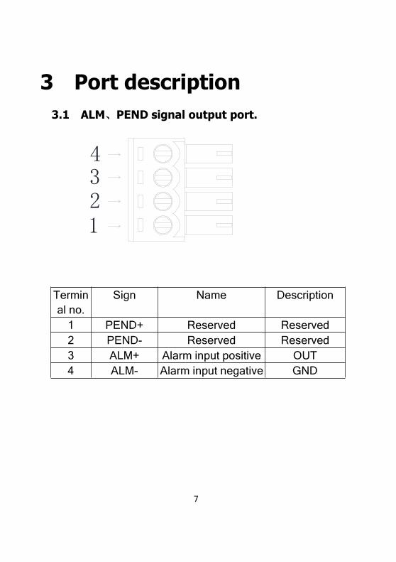
3 Port description3.1 ALM、PEND signal output port.
4321
Terminal no.
Sign Name Description
1 PEND+ Reserved Reserved2 PEND- Reserved Reserved3 ALM+ Alarm input positive OUT4 ALM- Alarm input negative GND
8
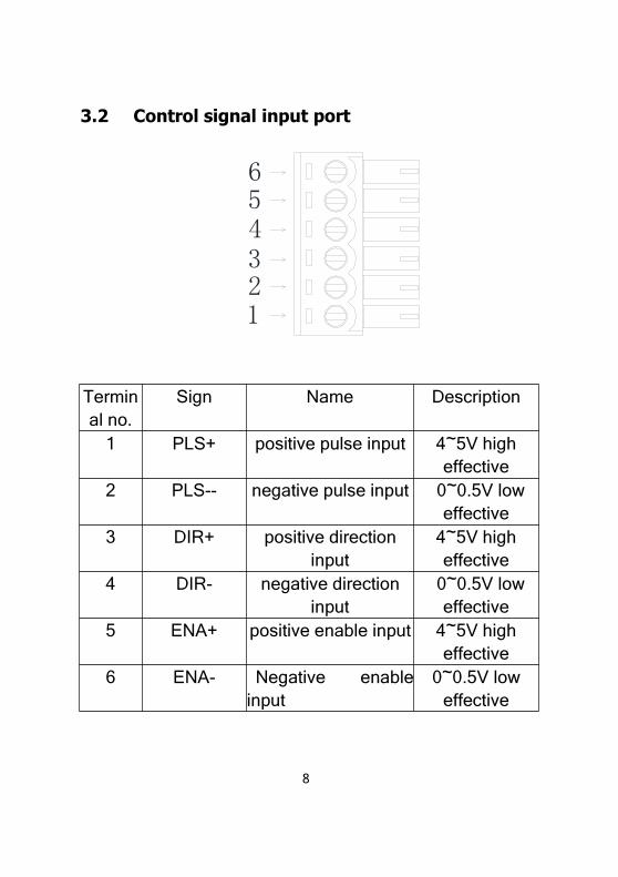
3.2 Control signal input port
654321
Terminal no.
Sign Name Description
1 PLS+ positive pulse input 4~5V higheffective
2 PLS-- negative pulse input 0~0.5V loweffective
3 DIR+ positive directioninput
4~5V higheffective
4 DIR- negative directioninput
0~0.5V loweffective
5 ENA+ positive enable input 4~5V higheffective
6 ENA- Negative enableinput
0~0.5V loweffective
.
9
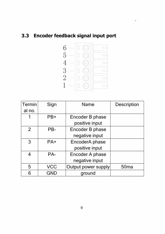
3.3 Encoder feedback signal input port
654321
Terminal no.
Sign Name Description
1 PB+ Encoder B phasepositive input
2 PB- Encoder B phasenegative input
3 PA+ EncoderA phasepositive input
4 PA- Encoder A phasenegative input
5 VCC Output power supply 50ma6 GND ground
10
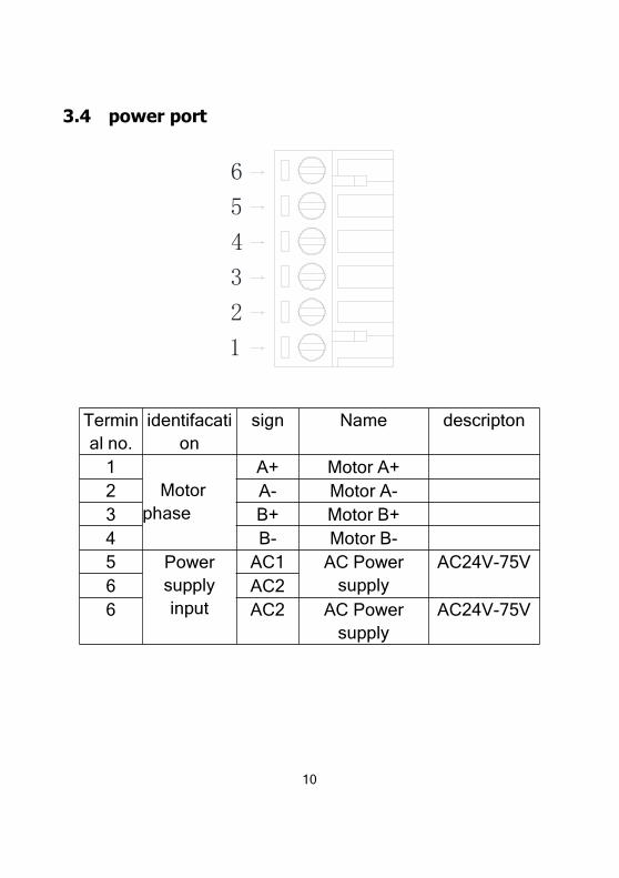
3.4 power port
6
5
4
3
2
1
Terminal no.
identifacation
sign Name descripton
1Motor
phase
A+ Motor A+2 A- Motor A-3 B+ Motor B+4 B- Motor B-5 Power
supplyinput
AC1 AC Powersupply
AC24V-75V6 AC26 AC2 AC Power
supplyAC24V-75V
11
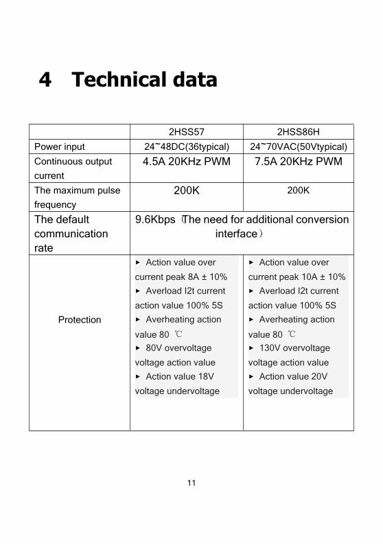
4 Technical data
2HSS57 2HSS86H
Power input 24~48DC(36typical) 24~70VAC(50Vtypical)
Continuous output
current
4.5A 20KHz PWM 7.5A 20KHz PWM
The maximum pulse
frequency
200K 200K
The defaultcommunicationrate
9.6Kbps(The need for additional conversioninterface)
Protection
▸ Action value over
current peak 8A ± 10%
▸ Averload I2t current
action value 100% 5S
▸ Averheating action
value 80 ℃
▸ 80V overvoltage
voltage action value
▸ Action value 18V
voltage undervoltage
▸ Action value over
current peak 10A ± 10%
▸ Averload I2t current
action value 100% 5S
▸ Averheating action
value 80 ℃
▸ 130V overvoltage
voltage action value
▸ Action value 20V
voltage undervoltage

12
2HSS57 2HSS86H
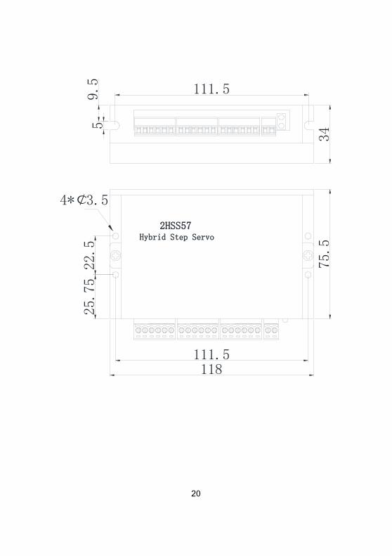
Overall dimensions 111.5×75.5×34 150×97.5×53
Weight About 300 grams About 580 grams
Environm
ent
Occasions Avoid dust, oil mist and corrosive gases
Working
temperature
0~+70℃
Storage
temperature
-20℃~+80℃
Humidity 40~90%RH
Cooling Natural cooling or forced air cooling
13
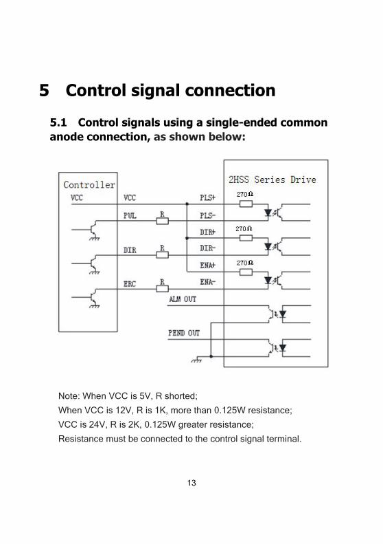
5 Control signal connection
5.1 Control signals using a single-ended commonanode connection, as shown below:
Note: When VCC is 5V, R shorted;
When VCC is 12V, R is 1K, more than 0.125W resistance;
VCC is 24V, R is 2K, 0.125W greater resistance;
Resistance must be connected to the control signal terminal.
14
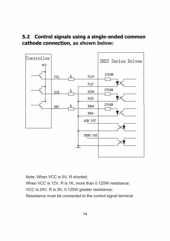
5.2 Control signals using a single-ended commoncathode connection, as shown below:
Note: When VCC is 5V, R shorted;
When VCC is 12V, R is 1K, more than 0.125W resistance;
VCC is 24V, R is 2K, 0.125W greater resistance;
Resistance must be connected to the control signal terminal.
.
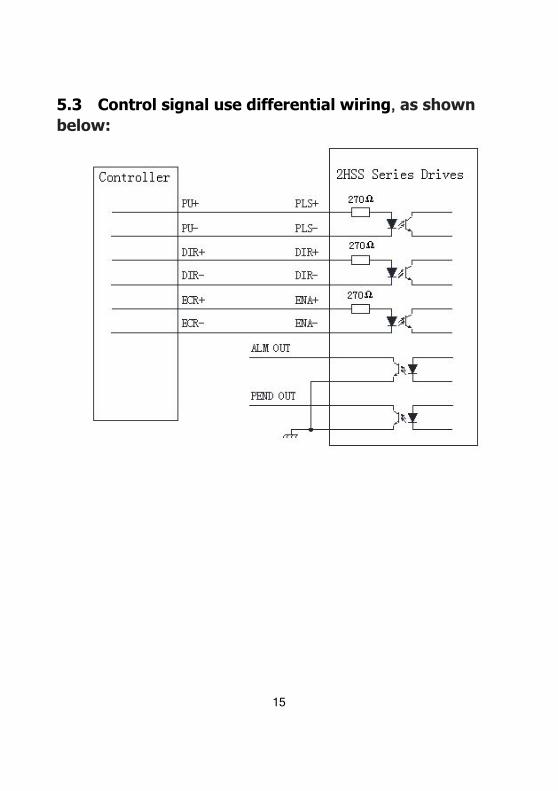
16
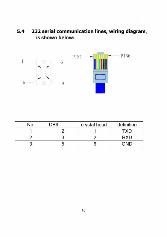
5.4 232 serial communication lines, wiring diagram,is shown below:
1
5
6
9
PIN1 PIN6
No. DB9 crystal head definition1 2 1 TXD2 3 2 RXD3 5 6 GND
17
6 DIP switch settings subdivision
6.1 quiescent current setting
SW1 DIP switch setting quiescent current, off meanshalf the quiescent current is set to dynamic currents, onsaid quiescent current and dynamic current is the same.
6.2 logical direction setting
When DIP switch SW2 is switched off or on, you canchange the direction of the current motor sport, off = CCW, on= CW.
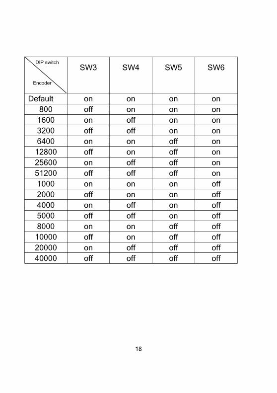
6.3 Subdivision settings
subdivision setting as the table below, When SW3,SW4, SW5, SW6 are set to on, the default internal electronicgear ratio has school, internal electronic gear ratio setting withJmcStepMotor software.
18
DIP switch
Encoder
SW3 SW4 SW5 SW6
Default on on on on800 off on on on
1600 on off on on3200 off off on on6400 on on off on
12800 off on off on25600 on off off on51200 off off off on1000 on on on off2000 off on on off4000 on off on off5000 off off on off8000 on on off off
10000 off on off off20000 on off off off40000 off off off off
19
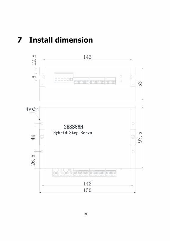
7 Install dimension
2HSS86HHybrid Step Servo
150
97.5
53
142
12.8
644
4*¢ 4
26.5
142
21
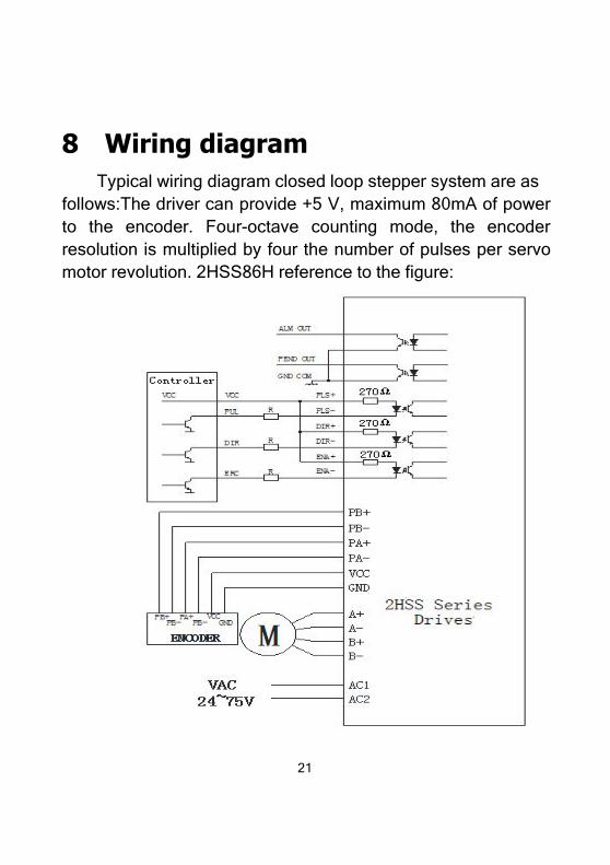
8 Wiring diagramTypical wiring diagram closed loop stepper system are as
follows:The driver can provide +5 V, maximum 80mA of powerto the encoder. Four-octave counting mode, the encoderresolution is multiplied by four the number of pulses per servomotor revolution. 2HSS86H reference to the figure:
22
9 closed-loop stepper system para-
meter adjustment and settings
Closed-loop stepper system parameter control via adedicated communication software serial ver set to adjust,serial ver software with system configuration, PID parameteradjustment, waveform acquisition, motion control and otherfunctions.
9.1 connection
1) Make sure that the drive is compatible with motorStepper drives and stepper motor to the normal
operationshould be paired with each other and achieve the desired
results,before the connection should confirm whether the compatible.Or else may damage the motor and drive.
2) a hardware configurationPC (desktop or laptop)
Requirements:CPU: Intel Pentium Ⅱ above gradeMemory: 64M or moreHard disk: 2GB or more

23
Display: Support for the resolution of 800 × 600 color displayaboveRS-232 serial communication interface: at least one

24
3) Software Operating System:Win95/Win98/WindowsNT/Windows 2000 / XPServo control software: serial ver
4) Communication CablesThis product is ready to connect the drive unit is located in
front of the terminal, and computer terminals dedicated RS-232connection cable (sold separately). The cable will be
connectedto the computer 232 level turn into TTL level for two differentlevels of communication connections.Communications cable specifications:
PC interface: DB9 Female
Device Interface: RJ-11 terminal
Length: 1m
5) hardware connection
25
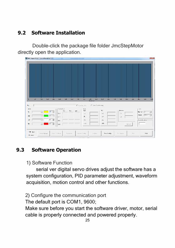
9.2 Software Installation
Double-click the package file folder JmcStepMotordirectly open the application.
9.3 Software Operation
1) Software Functionserial ver digital servo drives adjust the software has a
system configuration, PID parameter adjustment, waveformacquisition, motion control and other functions.
2) Configure the communication portThe default port is COM1, 9600;Make sure before you start the software driver, motor, serialcable is properly connected and powered properly.
26
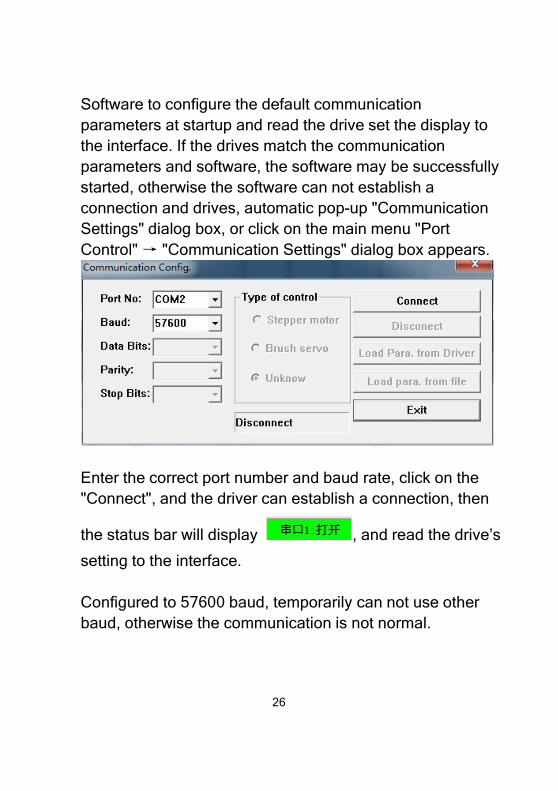
Software to configure the default communicationparameters at startup and read the drive set the display tothe interface. If the drives match the communicationparameters and software, the software may be successfullystarted, otherwise the software can not establish aconnection and drives, automatic pop-up "CommunicationSettings" dialog box, or click on the main menu "PortControl" → "Communication Settings" dialog box appears.
Enter the correct port number and baud rate, click on the"Connect", and the driver can establish a connection, then
the status bar will display , and read the drive’s
setting to the interface.
Configured to 57600 baud, temporarily can not use otherbaud, otherwise the communication is not normal.
27
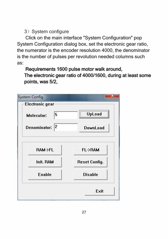
3)System configureClick on the main interface "System Configuration" pop
System Configuration dialog box, set the electronic gear ratio,the numerator is the encoder resolution 4000, the denominatoris the number of pulses per revolution needed columns suchas:
Requirements 1600 pulse motor walk around,The electronic gear ratio of 4000/1600, during at least somepoints, was 5/2,
28
After setting the electronic gear ratio, just click to download,either the value written to the drive, the drive inside the uploadparameters can be read out to confirm whether the downloadwas successful.
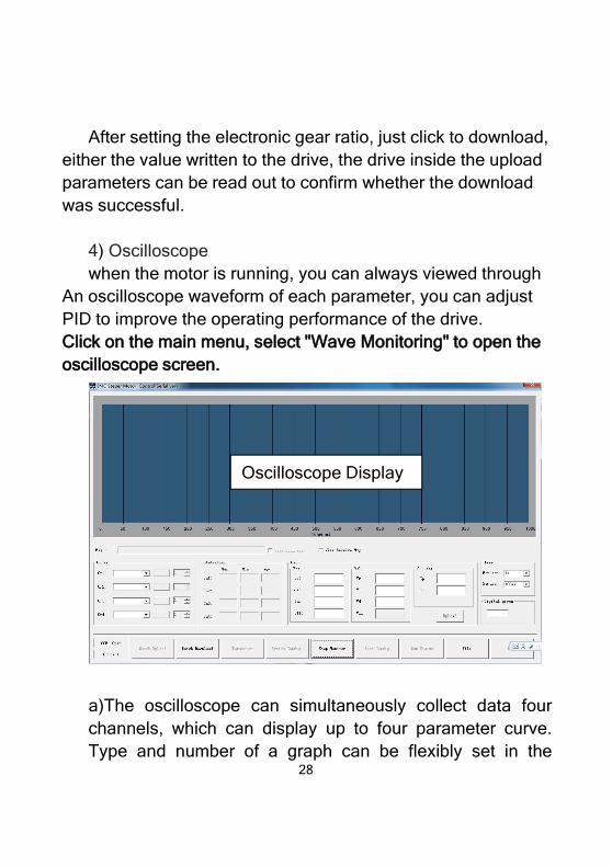
4) Oscilloscopewhen the motor is running, you can always viewed through
An oscilloscope waveform of each parameter, you can adjustPID to improve the operating performance of the drive.Click on the main menu, select "Wave Monitoring" to open theoscilloscope screen.
a)The oscilloscope can simultaneously collect data fourchannels, which can display up to four parameter curve.Type and number of a graph can be flexibly set in the
Oscilloscope Display
29
"Settings" tab. Sampling time and the baud rate used, thehigher the baud rate, the faster sampling, it isrecommended to use 115200 baud rate.b) Monitoring the time window you can select the option todisplay the range of time.c) Adjusting the PID parameters can be carried out in the"gain" tab adjustment, press the Enter key after modifyingparameters can be downloaded to the drive parameterstake effect immediately.d) "Statistics" tab to see the maximum, minimum andaverage values for each channel in the collected data.e) When the data display range greatly exceeds the latestcollected data, you can click scale "Refresh" button toadjust the scale.
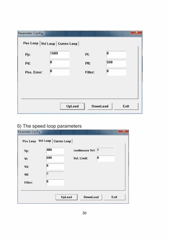
5) Position loop parameter settingsClick on the main interface "position loop" button to pop up
the position loop parameter settings dialog box. You can setthe
position proportion, Position feedforward,position differential,electronic gear numerator and denominator and fault protectionvalue, modify the parameter press the Enter key or press the"OK" button to download the parameters to the
drive,parameterstake effect immediately.
31
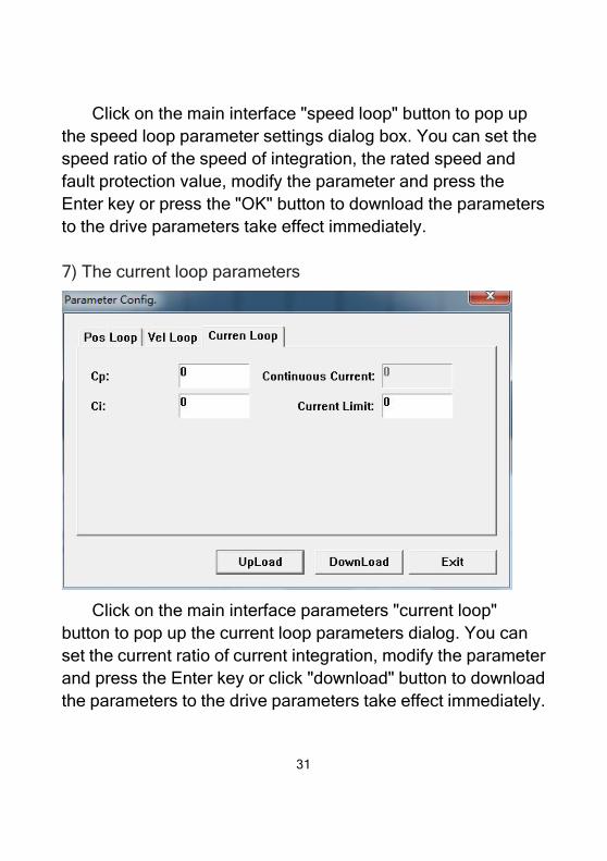
Click on the main interface "speed loop" button to pop upthe speed loop parameter settings dialog box. You can set thespeed ratio of the speed of integration, the rated speed andfault protection value, modify the parameter and press theEnter key or press the "OK" button to download the parametersto the drive parameters take effect immediately.
7) The current loop parameters
Click on the main interface parameters "current loop"button to pop up the current loop parameters dialog. You canset the current ratio of current integration, modify the parameterand press the Enter key or click "download" button to downloadthe parameters to the drive parameters take effect immediately.
32
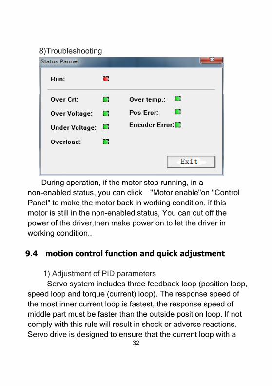
8)Troubleshooting
During operation, if the motor stop running, in anon-enabled status, you can click "Motor enable"on "ControlPanel" to make the motor back in working condition, if thismotor is still in the non-enabled status, You can cut off thepower of the driver,then make power on to let the driver inworking condition..
9.4 motion control function and quick adjustment
1) Adjustment of PID parametersServo system includes three feedback loop (position loop,
speed loop and torque (current) loop). The response speed ofthe most inner current loop is fastest, the response speed ofmiddle part must be faster than the outside position loop. If notcomply with this rule will result in shock or adverse reactions.Servo drive is designed to ensure that the current loop with a
.
33
good response performance. Users only need to adjust theposition loop and speed loop parameters. Between the variousparameters of the system is always mutual restraint, if only theposition loop gain is increased, the output command of theposition loop may become unstable, resulting in the entireservo system response may become unstable. Usually canadjust the system according to following steps:
Set the position feedforward and position differential to 500,
the position gain and velocity gain first set at a lower value1000, then under condition of no abnormal noise andvibration, gradually increase the speed gain until there is avibration then reduce at least 500-300.
Increase position gain until have vibration. Then increase
the position differential until no vibration.
Increase the position feedforward to have a lag and
minimum overshoot.
If the motor is running with vibration, reduce the speed gain
appropriately.
If the motor have a vibration when stopped, reduce the
position gain appropriately or increase the positiondifferential.
34
If the motor have electromagnetic noise, reduce the current
gain appropriately.
If the entire response have no overshoot, and vibration,should set the position gain to a maximum value. Thenfine-tuning speed gain,position feedforward and positiondifferential to find the best value.
10 Common Problems and Trouble-
Shooting10.1 Power-on Have red alert when power-on
Check whether the feedback signal cable is connected with
the motor electrical power phase cable.
Whether the servo drive input voltage is too high or too low.
10.2 Have a red alarm after running a small angle
In the parameter of the driver, phase motor phase
sequence is properly connected. Refer incorrectly identifiesthe drive motor phase sequence correspondingconnection.
Pulse input speed is greater than the rated speed ,have a
35
position out tolerance.
10.3 Not rotate after pulse input
Whether the connection of servo drive’s pulse input
terminal is reliable.
Whether the servo driver’s input mode is related with the
pulse input.
Whether the motor disabling is released.
10.4 Under speed control mode, when turning at lowspeed faster or slower
Reduce the speed proportion and increase the speed
integration until the speed is normal.