user s manual - cncshop.cz · user’s manual for ... either the motor or the encoder is wired in...
TRANSCRIPT

User’s Manual For
ProTuner 1.0.1.810 Windows Based Setup Software for Tuning Leadshine’s Digital Servo Driver
Revision 1.0 ©2008 All Rights Reserved
Attention: Please read this manual carefully before tuning the driver!
3/F, Block 2, Nanyou Tianan Industrial Park, Nanshan Dist, Shenzhen, China Tel: (86)755-26434369 Fax: (86)755-26402718
URL: www.leadshine.com E-Mail: [email protected]
The content in this manual has been carefully prepared and is believed to be accurate, but no responsibility is assumed for inaccuracies.
Leadshine reserves the right to make changes without further notice to any products herein to improve reliability, function or design. Leadshine does not assume any liability arising out of the application or use of any product or circuit described herein; neither does it convey any license under its patent rights of others.
Leadshine’s general policy does not recommend the use of its products in life support or aircraft applications wherein a failure or malfunction of the product may directly threaten life or injury. According to Leadshine’s terms and conditions of sales, the user of Leadshine’s products in life support or aircraft applications assumes all risks of such use and indemnifies Leadshine against all damages.
©2008 by Leadshine Technology Company Limited.
All Rights Reserved

Contents
Tel: (86)755-26434369 I Web site: www.leadshine.com
Table of Contents
1. Introduction ............................................................................................................. 1 2. Software Installation ............................................................................................... 1 3. Connections and Testing ......................................................................................... 5
RS232 Interface Connection................................................................................. 5 Testing the servo................................................................................................... 5
4. Software Introduction.............................................................................................. 7 ProTuner Main Window....................................................................................... 7 Com Config Window............................................................................................ 8
5. Servo Tuning ......................................................................................................... 16 Introduction ........................................................................................................ 16 Position Loop Introduction................................................................................. 18
Position around Velocity ........................................................................... 18 Position around Torque ............................................................................. 18
Position Loop Tuning ......................................................................................... 19
UUsseerr’’ss MMaannuuaall ffoorr tthhee PPrrooTTuunneerr RReevv11..00
Tel: (86)755-26434369 1 Web site: www.leadshine.com
1. Introduction
This manual will provide an overview of connection and basic setup instructions for Leadshine’s digital servo driver DCS810 using the ProTuner software. The basic setup of a digital driver is designed to be analogous to the setup and tuning of an analog amplifier. These instructions will walk you through the following steps necessary to start up your driver and motor. This document is intended for setting up the driver with the ProTuner.
2. Software Installation
The ProTuner is windows based setup software for tuning Leadshine’s digital servo drivers. It can run in windows systems, including Win95/Win98/WindowsNT/ Windows 2000/Windows XP. And the selected PC should have 1 serial port at least for communicating with the driver.
Double click “ProTuner_DCS810.exe” to begin installing the ProTuner. See Figure 1. Click Next to enter the “License Agreement” window. See Figure 2.
Figure 1: Begin to install the ProTuner

UUsseerr’’ss MMaannuuaall ffoorr tthhee PPrrooTTuunneerr RReevv11..00
Tel: (86)755-26434369 2 Website: www.leadshine.com
Figure 2: License agreement
Choose “I agree to the terms of this license agreement” and click Next to continue installation. The user can enter user’s information in the following window. See Figure 3. After entering the user’s information, click Next to select installation folder, where you would like to install the ProTuner. See Figure 4.
Figure 3: User’s information settings
UUsseerr’’ss MMaannuuaall ffoorr tthhee PPrrooTTuunneerr RReevv11..00
Tel: (86)755-26434369 3 Website: www.leadshine.com
Figure 4: Installation folder settings
Figure 5: Shortcut folder setting
Set the “Shortcut Folder” in Figure 5 and continue to install the ProTuner by following Figure 6 and Figure 7. An Installation Successful window will appear if the ProTuner is installed successfully. See Figure 8.

UUsseerr’’ss MMaannuuaall ffoorr tthhee PPrrooTTuunneerr RReevv11..00
Tel: (86)755-26434369 4 Website: www.leadshine.com
Figure 6: Installation information summarization
Figure 7: Installing the ProTuner
UUsseerr’’ss MMaannuuaall ffoorr tthhee PPrrooTTuunneerr RReevv11..00
Tel: (86)755-26434369 5 Website: www.leadshine.com
Figure 8: Finish installation
3. Connections and Testing
Connect the servo system according to “User’s Manual for the DCS810” and connect the PC to the driver as the following figure.
RS232 Interface Connection
Figure 9: RS232 interface connection
Testing the servo
You may wish to secure the motor so it can’t jump off the bench. Turn on the power supply, the green (Power) LED will light. The DCS810 has default

UUsseerr’’ss MMaannuuaall ffoorr tthhee PPrrooTTuunneerr RReevv11..00
Tel: (86)755-26434369 6 Website: www.leadshine.com
parameters stored in the driver. If the system has no hardware and wirings problem, the motor should be locked and the driver should be ready.
If the motor jumps slightly and the red LED immediately turns on (flickers), then either the motor or the encoder is wired in reversal. Open the tuning software ProTuner and check driver status by clicking Err_check. If it’s Phase Error, then reversal motor wires or exchange encoder inputs and try again. If it’s Encoder Error, please check encoder and its wirings, and then try again. If it still doesn’t work after you followed all of the previous steps, please contact us at [email protected].
If the red LED is off and the motor is normal, then you can start to tune the servo with ProTuner. However, we recommend you see the following contents before starting tuning.
UUsseerr’’ss MMaannuuaall ffoorr tthhee PPrrooTTuunneerr RReevv11..00
Tel: (86)755-26434369 7 Website: www.leadshine.com
4. Software Introduction
ProTuner Main Window
Figure 10: ProTuner
Ø Option
The user can choose three drop-down menus by clicking “Option”, including Com Config, SaveToDriver and Exit.
l Com Config: Configure Com communication interface. l SaveToDriver: Download the current parameter settings to the driver. l Exit: Exit the ProTuner.
Menu Bar
Status Bar
UUsseerr’’ss MMaannuuaall ffoorr tthhee PPrrooTTuunneerr RReevv11..00
Tel: (86)755-26434369 8 Website: www.leadshine.com
Com Config Window
Figure 11: RS232 communication configuration window
Serial Port: Select the serial communication port to which the driver is connected. The factory default setting is COM1.
Baud Rate: Select the communication baud rate. The factory default setting is 38400.
Click Open button to establish a connection with the specified settings. When connecting, you can choose SaveToDrive to download the current parameter settings to the driver, or to upload the stored driver settings into the ProTuner by clicking Tuning > Position Loop on the menu bar.
Ø Tuning
The user can choose one or two drop-down menu(s) by clicking Tuning, including CurrentLoop (Only exist in special version.) and PositionLoop.
l PositionLoop: There are three tabs in Position Loop Tuning window, including P_parameter, T_Speed_Par, and CurveSetting tabs.
UUsseerr’’ss MMaannuuaall ffoorr tthhee PPrrooTTuunneerr RReevv11..00
Tel: (86)755-26434369 9 Website: www.leadshine.com
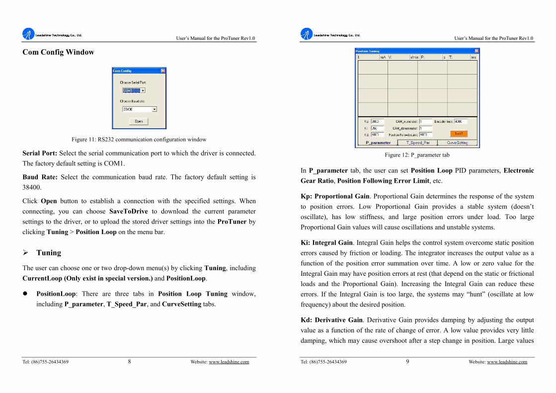
Figure 12: P_parameter tab
In P_parameter tab, the user can set Position Loop PID parameters, Electronic Gear Ratio, Position Following Error Limit, etc.
Kp: Proportional Gain. Proportional Gain determines the response of the system to position errors. Low Proportional Gain provides a stable system (doesn’t oscillate), has low stiffness, and large position errors under load. Too large Proportional Gain values will cause oscillations and unstable systems.
Ki: Integral Gain. Integral Gain helps the control system overcome static position errors caused by friction or loading. The integrator increases the output value as a function of the position error summation over time. A low or zero value for the Integral Gain may have position errors at rest (that depend on the static or frictional loads and the Proportional Gain). Increasing the Integral Gain can reduce these errors. If the Integral Gain is too large, the systems may “hunt” (oscillate at low frequency) about the desired position.
Kd: Derivative Gain. Derivative Gain provides damping by adjusting the output value as a function of the rate of change of error. A low value provides very little damping, which may cause overshoot after a step change in position. Large values

UUsseerr’’ss MMaannuuaall ffoorr tthhee PPrrooTTuunneerr RReevv11..00
Tel: (86)755-26434369 10 Website: www.leadshine.com
have slower step response but may allow higher Proportional Gain to be used without oscillation.
CAM_numerator: Numerator of Electronic Gear. Can be set from 1 to 255.
CAM_denominator: Denominator of Electronic Gear. Can be set from 1 to 255.
Position FollowErrLimit: Position Following Error Limit. The limit of the difference between commanded position and the actual measured position. When position following error reaches Position Following Error Limit parameter setting in the driver, the protection will be activated.
Encoder Lines: Encoder Line Count. The DCS810 supports single-ended and differential-ended incremental encoders. Here, one thing should explained is that the Encoder Lines parameter in this tab is just for self-test motion controller during tuning, and will not affect the driver to interpret the encoder feedback signal. With regard to the DCS810, feedback resolution is ×4 encoder line count.
Start/Stop button: The user can start or stop self-test by clicking this button.
Figure 13: T_Speed_Par tab
UUsseerr’’ss MMaannuuaall ffoorr tthhee PPrrooTTuunneerr RReevv11..00
Tel: (86)755-26434369 11 Website: www.leadshine.com
In T_Speed_Par tab, the user can set velocity profile for self motion test and tuning, including Maximum Speed, Acceleration, position move Distance of trapezoidal velocity profile, and Interval, Repeat Times of self motion test.
V_top: Maximum Speed. The maximum speed of trapezoidal velocity profile. Its unit is RPM.
Accel: Acceleration. The acceleration of trapezoidal velocity profile. Its unit is (r/s)/s.
Length: Distance. The distance required to move. Its unit is pulse (count).
Interval: The interval between positive rotation and negative movement.
Repeat_times: The repeat times of positive and negative movement.
Start/Stop button: The user can start or stop self-test by clicking this button.
Figure 14: CurveSetting tab
In CurveSetting tab, the user can choose curves displayed in digital scope of Position Loop Tuning window and DigitalMonitor window, and set their Trace Time. These curves includes Current Following Error (i_err), Velocity

UUsseerr’’ss MMaannuuaall ffoorr tthhee PPrrooTTuunneerr RReevv11..00
Tel: (86)755-26434369 12 Website: www.leadshine.com
Following Error (v_err), Position Following Error (p_err), Current Feedback (i_bak), Velocity Feedback (v_bak), Position Feedback (p_bak), Current Command (i_ref), Velocity Command (v_ref), Position Command (p_ref).
i_err: Current Following Error. The difference between commanded current and the actual measured current.
v_err: Velocity Following Error. The difference between commanded velocity and the actual measured velocity.
p_err: Position Following Error. The difference between commanded position and the actual measured position.
i_bak: Current Feedback. This is the actual measured current in motor coil. Ideally, this value should be as close as possible to the commanded current.
v_bak: Velocity Feedback. This is the actual measured velocity measured by the encoder. Ideally, this value should be as close as possible to the commanded velocity.
p_bak: Position Feedback. This is the actual measured position measured by the encoder. Ideally, this value should be as close as possible to the commanded position.
i_ref: Current Command. This is the commanded current.
v_ref: Velocity Command. This is the commanded velocity.
p_ref: Position Command. This is the commanded position.
Trace Time: Trace Time. This is the trace time of the digital scope.
Start/Stop button: The user can start or stop self-test by clicking this button.
UUsseerr’’ss MMaannuuaall ffoorr tthhee PPrrooTTuunneerr RReevv11..00
Tel: (86)755-26434369 13 Website: www.leadshine.com
Ø Digital_monitor
l Digital Monitor: Displays curves and dynamic values of different point of different curves.
Figure 15: Digital scope window
I: Current. Displays dynamic values for Current related curve(s). Dynamic value will change with mouse focus changes. Its unit is mA.
V: Velocity. Displays dynamic values for Velocity related curve(s). Dynamic value will change with mouse focus changes. Its unit is r/min.
P: Position. Displays dynamic values for Position related curve(s). Dynamic value will change with mouse focus changes. Its unit is pulse (count).
T: Time. Displays dynamic values for Time. Dynamic value will change with mouse focus changes. Its unit is ms.

UUsseerr’’ss MMaannuuaall ffoorr tthhee PPrrooTTuunneerr RReevv11..00
Tel: (86)755-26434369 14 Website: www.leadshine.com
Ø Err_check
l Error Check: This window shows both the present status of each error event and their history. Current error event(s) can be reset by clicking Erase Current Err! button, and all error events can be reset by clicking Erase All! button.
Figure 16: Error check window
OverCurrent: Over-current Protection. Protection will be activated when continuous current exceeds 20A.
OverVoltage: Over-voltage Protection. When power supply voltage exceeds 85±1.5 VDC, protection will be activated.
LowVoltage: Under-voltage Protection. When power supply voltage is lower than 16.5±1.5 VDC, protection will be activated.
PhaseErr: Phase Error Protection. Motor power lines wrong & not connected and encoder feedback signals A/B phases wrong connected will activate this protection.
EncoderErr: Encoder Error Protection. No encoder feedback signals or wrong encoder feedback signals will activate this protection.
UUsseerr’’ss MMaannuuaall ffoorr tthhee PPrrooTTuunneerr RReevv11..00
Tel: (86)755-26434369 15 Website: www.leadshine.com
FollowingErr: Position Following Error Limit Protection. When position following error reaches Position Following Error Limit parameter setting in the driver, this protection will be activated.
ErrCounter: Displays current error(s) and current error history.
Erase Current Err!: Erase Current Err button. The user can clear current error(s) by clicking this button.
Erase All!: Erase All! button. The user can clear all error(s) including error history by clicking this button.
Ø About
The user can choose two drop-down menus by clicking “About”, including Product Information and Contact Us.
l Product Information window: Shows some product information about ProTuner.
l Contact Us window: Shows some contact information about Leadshine.
Figure 17: Product information

UUsseerr’’ss MMaannuuaall ffoorr tthhee PPrrooTTuunneerr RReevv11..00
Tel: (86)755-26434369 16 Website: www.leadshine.com
Figure 18: Contact information
5. Servo Tuning
Introduction
A servo system is error-driven. The “Gain” of the system determines how hard the servo tries to reduce the error. A high-gain system can produce large correcting torques when the error is very small. A high gain is required if the output is required to follow the input faithfully with minimal error.
A servo motor and its load both have inertia, which the servo amplifier must accelerate and decelerate while attempting to follow a change at the input. The presence of the inertia will tend to result in over-correction, with the system oscillating beyond either side of its target. It’s called UNDER DAMPED status. See Figure 19. This oscillation must be damped, but too much damping will cause the response to be sluggish, namely cause the system to get into an OVER DAMPED state. When we tune a servo, we are trying to achieve the fastest response with little or no overshoot, namely get a CRITICALLY DAMPED response.
UUsseerr’’ss MMaannuuaall ffoorr tthhee PPrrooTTuunneerr RReevv11..00
Tel: (86)755-26434369 17 Website: www.leadshine.com
Figure 19: Step and impulse responses
As mentioned in previous contents, the DCS810 is a digital servo driver and its input command is PUL/DIR signal. In other words, step response just exists in each step command signal. For each step command signal is a very small movement, so OVER SHOOT and SETTLING TIME between each step are very small, causing you hardly can see a step response such as Figure 19, even if the SET POINT is a very large quantity and the acceleration is very high.
However, if you try to evaluate performances of the digital servo by investigating its position tracking-error or position following error, you may find it’s much easier than investigating its step response. The easiest way to get a tracking-error or position following error response is to induce an impulse load on the motor. See Figure 19 at “time 20”.
Leadshine offer a Windows based setup software ProTuner and a special text monitor EZ-Tuner (optional) to its customers for evaluating servo performances. Small servo tuning unit STU (optional) is available too, and it’s for field tuning without PC or power supply for the EZ-Tuner. The paper will walk you through

UUsseerr’’ss MMaannuuaall ffoorr tthhee PPrrooTTuunneerr RReevv11..00
Tel: (86)755-26434369 18 Website: www.leadshine.com
following contents necessary to start up your driver and motor with ProTuner.
Position Loop Introduction
Position loop tuning is dependant on the mechanical load, and therefore will change with any mechanical system changes. Position loop tuning should be performed with the motor installed in the system. The position loop can be closed around velocity or torque mode (depending on whether the velocity loop is enabled or disabled). If it is closed around velocity mode, the position loop algorithm output becomes the new velocity set point. If it is closed around torque mode, the position loop algorithm output becomes the new torque set point. There are some important differences in the tuning process and application of these two approaches:
Position around Velocity: This mode is most common in "contouring" application, where a position trajectory must be tracked very closely. The velocity loop provides additional "stiffness", and keeps the dynamic position errors minimal, since the system now reacts to not just position errors, but also velocity errors (which can be interpreted as position error changes). It is important to start with a stable yet responsive velocity loop. Typically, it is sufficient to just use the position loop proportional gain. Feedforward gain can be added to improve tracking performance (i.e. minimize the difference between commanded and actual position). The velocity loop is disabled in current version DCS810, and it adopts Position around Current (Torque) mode.
Position around Torque: This mode is most common in point-to-point applications, where actual motion between start and end point is not very critical. In this case, velocity loop tuning can be avoided. This can be advantageous if the velocity feedback is poor (e.g. low resolution encoder, poor encoder quadrature.). In this case, the tuning process requires that the position loop proportional and derivative gain are increased simultaneously, unless the system has sufficient friction, in which case no derivative gain is necessary. Once a stable
UUsseerr’’ss MMaannuuaall ffoorr tthhee PPrrooTTuunneerr RReevv11..00
Tel: (86)755-26434369 19 Website: www.leadshine.com
response is achieved, integral gain can be added to improve stiffness. It is best to use a step command with the profiler enabled as a reference signal during tuning.
Driver tuning is a multi-step process that involves proper tuning of up to three different servo loops, namely current loop, velocity loop and position loop. You can either tune the position loop around the velocity loop, or around the current loop. Generally, it is much easier to tune a position loop around a velocity loop because only the proportional gain is needed. When tuning position around the current loop, a high derivative gain may be necessary on top of both proportional and integral gains.
For most of the DCS810 drivers have been being sold to the customers with Leadshine’s DCM5xxxx DC servo motors, Leadshine will tune the current loop before sending drivers out of the factory. Leadshine just offer a special version ProTuner to some customers for tuning current loop, while most of customers just need to tune the position loop parameters with the standard version if they use the drivers with Leadshine’s DCM5xxxx DC servo motors. If you use the DCS810 with DC servo motors from other manufacturers and current loop tuning is needed. Please contact Leadshine for special version ProTuner to tune the current loop.
Follow the steps below for tuning the driver with the standard version ProTuner.
Position Loop Tuning
Set the parameters and select the curves displayed in Digital Monitor before starting self-test and tuning. See Figure 20 and Figure 21 for the parameters for the tuning in this paper. When we tune a servo, we are trying to achieve the fastest response with little or no overshoot, namely get a Critically Damped response.

UUsseerr’’ss MMaannuuaall ffoorr tthhee PPrrooTTuunneerr RReevv11..00
Tel: (86)755-26434369 20 Website: www.leadshine.com
Figure 20: Self-test motion settings for the tuning
Figure 21: Digital Scope settings for the tuning
As mentioned above, the DC810 adopts position around current (torque) mode, and when tuning position around the current loop, a high derivative gain may be necessary on top of both proportional and integral gains. Here, we set Kp=1000, Ki=0, Kd=500 first, and the self-test result is shown in Figure 22.
UUsseerr’’ss MMaannuuaall ffoorr tthhee PPrrooTTuunneerr RReevv11..00
Tel: (86)755-26434369 21 Website: www.leadshine.com
Figure 22: Position following error curve and velocity curve (Kp=1000, Ki=0 and Kd=500)
It’s very easy to see from the velocity curve (Green line) that the system is under damped. This will cause system oscillating beyond either side of its target, so it must be damped. Figure 23 shows the result after increasing Kd to 1500. In the Figure 23, the oscillation is much smaller than that of Figure 22. You can get even smaller oscillation when increasing Kd to 3500. See Figure 24.
Figure 23: Position following error curve and velocity curve (Kp=1000, Ki=0 and Kd=1500)

UUsseerr’’ss MMaannuuaall ffoorr tthhee PPrrooTTuunneerr RReevv11..00
Tel: (86)755-26434369 22 Website: www.leadshine.com
Figure 24: Position following error curve and velocity curve (Kp=1000, Ki=0 and Kd=3500)
Although very smooth velocity curve had been gotten in Figure 24, we can see that the position following error is still too large to accept. And this can be improved by increasing Ki value. See Figure 25. However, we can see the system response in Figure 25 is already Over Damped, namely too much damping has caused the response to be sluggish. This can be improved by increasing Kp or reducing Kd. See Figure 26 and Figure 27. Here we try to improve the performances by increasing Kp.
UUsseerr’’ss MMaannuuaall ffoorr tthhee PPrrooTTuunneerr RReevv11..00
Tel: (86)755-26434369 23 Website: www.leadshine.com
Figure 25: Position following error curve and velocity curve (Kp=1000, Ki=100 and Kd=3500)
Figure 26: Position following error curve and velocity curve (Kp=2000, Ki=100 and Kd=3500)

UUsseerr’’ss MMaannuuaall ffoorr tthhee PPrrooTTuunneerr RReevv11..00
Tel: (86)755-26434369 24 Website: www.leadshine.com
Figure 27: Position following error curve and velocity curve (Kp=3000, Ki=100 and Kd=3500)
Increase Kd can reduce velocity overshoot, and get a better velocity curve in as shown in Figure 28.
Figure 28: Position following error curve and velocity curve (Kp=3000, Ki=100 and Kd=4000)
Since position following error is still large during constant speed period in Figure 28, we try to increase Ki to improve system’s performances. Figure 29, Figure 30,
UUsseerr’’ss MMaannuuaall ffoorr tthhee PPrrooTTuunneerr RReevv11..00
Tel: (86)755-26434369 25 Website: www.leadshine.com
and Figure 31 show the result after increasing Ki. From Figure 31, we can see that too much Ki will cause position curve over shoot.
Figure 29: Position following error curve and velocity curve (Kp=3000, Ki=200 and Kd=4000)
Figure 30: Position following error curve and velocity curve (Kp=3000, Ki=600 and Kd=4000)

UUsseerr’’ss MMaannuuaall ffoorr tthhee PPrrooTTuunneerr RReevv11..00
Tel: (86)755-26434369 26 Website: www.leadshine.com
Figure 31: Position following error curve and velocity curve (Kp=3000, Ki=700 and Kd=4000)
Increasing Kp a little and reducing Ki to 600 can achieve a faster response with little overshoot, namely get a response close to Critically Damped response. See Figure 32. Remember to download the parameter settings to the driver’s EEPROM when you get satisfying performances.
Figure 32: Position following error curve and velocity curve (Kp=3200, Ki=600 and Kd=4000)
UUsseerr’’ss MMaannuuaall ffoorr tthhee PPrrooTTuunneerr RReevv11..00
Tel: (86)755-26434369 27 Website: www.leadshine.com
Figure 33: Position following error curve and velocity curve (Kp=3000, Ki=700 and Kd=4000)
Tuning servo systems formed by DCS810 drivers can be summarized as the following rules:
1. If servo system is UNSTABLE, then the first thing of tuning is to stabilize the system. You can increase Derivative Gain of Position Loop (Kd) or decrease Proportional Gain of Position Loop (Kp) or Integral Gain of Position Loop (Ki).
2. If servo system is UNDER DAMPED, then increase Kd or decrease Kp or Ki. 3. If servo system is CRITICALLY DAMPED, then stop tuning and download the
parameter settings to the driver’s EEPROM. 4. If servo system is OVER DAMPED, then decrease Kd or increase Kp or Ki.
Remember that tuning the servo is to get satisfying performances, getting the best performances of the servo is a time consuming work. So if the servo performance can meet your application requirements, then the easier tuning way the better. Just like if the performances of the products can meet your application requirements, then the cheaper the better.