user’s guide megaraid configuration softwaredb15-000269-00 megaraid® configuration software...
TRANSCRIPT

®
DB15-000269-00
MegaRAID®
Configuration Software
USER’SGUIDE
F e b r u a r y 2 0 0 3
Version 1.0

iiVersion 1.0 Copyright © 2003 by LSI Logic Corporation. All rights reserved.
This document contains proprietary information of LSI Logic Corporation. Theinformation contained herein is not to be used by or disclosed to third partieswithout the express written permission of an officer of LSI Logic Corporation.
LSI Logic products are not intended for use in life-support appliances, devices,or systems. Use of any LSI Logic product in such applications without writtenconsent of the appropriate LSI Logic officer is prohibited.
Document DB15-000269-00, First Edition (February 2003)This document describes LSI Logic Corporation’s MegaRAID software tools andutilities. This document will remain the official reference source for allrevisions/releases of these products until rescinded by an update.
LSI Logic Corporation reserves the right to make changes to any products hereinat any time without notice. LSI Logic does not assume any responsibility orliability arising out of the application or use of any product described herein,except as expressly agreed to in writing by LSI Logic; nor does the purchase oruse of a product from LSI Logic convey a license under any patent rights,copyrights, trademark rights, or any other of the intellectual property rights of LSILogic or third parties.
Copyright © 2003 by LSI Logic Corporation. All rights reserved.
TRADEMARK ACKNOWLEDGMENTLSI Logic, the LSI Logic logo design, FlexRAID, MegaRAID, MegaRAID Manager,Power Console Plus, and WebBIOS are trademarks or registered trademarks ofLSI Logic Corporation. All other brand and product names may be trademarks oftheir respective companies.
AP
To receive product literature, address your request to:
To receive product literature, visit us at http://www.lsilogic.com.
For a current list of our distributors, sales offices, and design resourcecenters, view our web page located at
http://www.lsilogic.com/contacts/index.html

MegaRAID Configuration Software User’s Guide iiiVersion 1.0 Copyright © 2003 by LSI Logic Corporation. All rights reserved.
Preface
This book is the primary reference and user’s guide for the MegaRAIDsoftware tools and utilities. These include the MegaRAID™ ConfigurationUtility (CU), WebBIOS™ CU, MegaRAID Manager™, and Power ConsolePlus™, which enable configuration and management of RAID systemsusing the MegaRAID controllers.
Audience
This document assumes that you have familiarity with storage systems,and are knowledgeable about PCI, SCSI, and Serial ATA interfaces. Italso assumes that you are familiar with computer systems and know howto use the keyboard, mouse, clipboard functions, toolbars, and drop downmenus.
The people who benefit from this book are:
• Users who want to configure, monitor, or manage RAID systems thatuse MegaRAID controllers
• Engineers and managers who are evaluating MegaRAID controllersfor use in a system
• Engineers who are designing MegaRAID controllers into a system
Organization
This document has the following chapters and appendixes:
• Chapter 1, Overview, introduces the MegaRAID software tools andutilities, and provides operating system information.
• Chapter 2, MegaRAID BIOS Configuration Utility, describes theMegaRAID BIOS CU.

iv PrefaceVersion 1.0 Copyright © 2003 by LSI Logic Corporation. All rights reserved.
• Chapter 3, WebBIOS Configuration Utility, describes the WebBIOSCU.
• Chapter 4, MegaRAID Manager, describes the MegaRAID Managertool.
• Chapter 5, Power Console Plus, describes the Power Console Plustool.
• Chapter 6, Virtual Sizing and Online Capacity Expansion,describes the Virtual Sizing feature for the MegaRAID CU,MegaRAID Manager tool, and Power Console Plus tool.
• Appendix A, MegaRAID Service Monitor, describes the messagesused by the MegaRAID Service Monitor.
MegaRAID System Installation Sequences and Document Organization
The following table outlines the installation, configuration, andmanagement sequences for a MegaRAID Serial ATA system. Eachsequence consists of a series of steps and operations that the referencemanual explains. LSI Logic recommends performing the sequences inthe order listed when you install and configure your Serial ATA system.
Sequence Task Reference Manual
1 Understand RAID system theory and operation. LSI Logic RAID Primer
2 Install the MegaRAID Serial ATA storage adapter and therelated hardware.
MegaRAID SATA150 User’sGuide
3 Configure the physical arrays and logical devices usingeither the MegaRAID Configuration Utility (CU) or the Web-BIOS CU.
MegaRAID ConfigurationSoftware User’s Guide
4 Install the MegaRAID device drivers. MegaRAID Device DriverInstallation User’s Guide
5 Manage, monitor, and re-configure the RAID array usingeither the MegaRAID Manager tool or the Power ConsolePlus tool. Each tool runs under an operating system andcan manage the RAID array while the system is operating.
MegaRAID ConfigurationSoftware User’s Guide

Preface vVersion 1.0 Copyright © 2003 by LSI Logic Corporation. All rights reserved.
LSI Logic RAID Primer
Document Number: DB09-000123-00
This document explains RAID. Refer to this guide for definitions involvingRAID and an explanation of RAID implementations.
SATA150-6 Quick Installation Guide
Document Number: DB11-000017-00
This document provides top-level installation instructions, jumperdefinitions, and connector locations. Use this document as a guide if youare already familiar with MegaRAID RAID Storage Adapter (RSA)installation and feel confident that you can installation a MegaRAID RSAin a PCI system.
MegaRAID SATA150 Storage Adapters User’s Guide
Document Number: DB15-000272-00
This document explains how to install your MegaRAID SATA150 storageadapter in the host system. It also provides the electrical and physicalspecifications, jumper definitions, and connector locations for the storageadapter.
MegaRAID Device Driver Installation User’s Guide
Document Number: DB11-000018-00
This document explains how to install the MegaRAID device driver foryour operating system. The information in this document is independentof the back-end bus and applies to both MegaRAID SCSI storageadapters and Serial ATA storage adapters.
MegaRAID Configuration Software User’s Guide
Document Number: DB15-000269-00
This document explains the various RAID system configuration,monitoring, and management tools that MegaRAID provides. Thisdocument provides step-by-step instructions for using the MegaRAID CUand WebBIOS CU BIOS-based utilities, as well as the MegaRAIDManager and Power Console Plus OS-based tools. The information inthis document is independent of the back-end bus and applies to bothMegaRAID SCSI storage adapters and Serial ATA storage adapters.

vi PrefaceVersion 1.0 Copyright © 2003 by LSI Logic Corporation. All rights reserved.
Conventions
Revision History
Technical Support
LSI Logic provides technical support only for LSI Logic productspurchased directly from LSI Logic or from an LSI Logic-authorizedreseller.
• If you purchased the MegaRAID controller from LSI Logic or from acertified LSI Logic reseller, call LSI Logic technical support at (678)728-1250. Please be prepared to specify the serial number of theproduct.
• If the MegaRAID controller was installed as part of a systemmanufactured by a company other than LSI Logic, or if youpurchased an LSI Logic product from an unauthorized reseller, callthe technical support department of the computer manufacturer orthe unauthorized reseller. LSI Logic does not provide direct technicalsupport in these cases.
Convention Definition Examples
Bold Buttons and tabs within GUIs are listed in bold. Next, Have Disk...
→ Used to indicate a series of selections in a GUI. Start → Programs
< > Key presses are enclosed in angle brackets. <F6>, <N>, <Enter>
Courier Screen Text, filenames, directory paths, and user-enteredcommands are listed in courier.
A:\Windows, Setupcould ...
Date Version Description
February 2003 1.0 Initial release of document

MegaRAID Configuration Software User’s Guide viiVersion 1.0 Copyright © 2003 by LSI Logic Corporation. All rights reserved.
Contents
Chapter 1Overview
1.1 MegaRAID Tool Description 1-11.1.1 MegaRAID Configuration Utility 1-11.1.2 WebBIOS Configuration Utility 1-21.1.3 MegaRAID Manager 1-21.1.4 Power Console Plus 1-2
1.2 Operating System Support 1-3
Chapter 2MegaRAID BIOS Configuration Utility
2.1 Quick Configuration Steps 2-12.2 MegaRAID BIOS Configuration Utility Menu 2-2
2.2.1 Configure Menu 2-32.2.2 Initialize Option 2-42.2.3 Objects Menu 2-42.2.4 Format Option 2-92.2.5 Rebuild Option 2-102.2.6 Check Consistency Option 2-102.2.7 Select Adapter Menu 2-10
2.3 Detailed Configuration Instructions 2-112.3.1 Starting MegaRAID Configuration Utility 2-112.3.2 Choosing a Configuration Method 2-112.3.3 Designating Hot Spare Drives 2-122.3.4 Configuring Physical Arrays and Logical Drives 2-122.3.5 Initializing Logical Drives 2-16
2.4 Configuration on Disk Description 2-172.5 Rebuilding Failed Disks 2-172.6 Using a Pre-loaded System Drive 2-18

viii ContentsVersion 1.0 Copyright © 2003 by LSI Logic Corporation. All rights reserved.
2.7 Exiting MegaRAID Configuration Utility 2-19
Chapter 3WebBIOS Configuration Utility
3.1 General Description 3-13.2 Quick Configuration Steps 3-23.3 Starting the WebBIOS Utility on the Host Computer 3-23.4 Screen and Option Descriptions 3-3
3.4.1 Toolbar Options 3-33.4.2 Main Screen 3-43.4.3 Adapter Properties Screen 3-43.4.4 Logical Drives Screen 3-53.4.5 Physical Drives Screen 3-63.4.6 Configuration Mismatch Screen 3-63.4.7 Configuration Wizard Option 3-7
3.5 Detailed Configuration Instructions 3-73.5.1 Write Policy 3-83.5.2 Cache Policy 3-9
Chapter 4MegaRAID Manager
4.1 Quick Configuration Steps 4-14.2 Main Menu Options 4-2
4.2.1 Configure Menu 4-34.2.2 Initialize Option 4-64.2.3 Objects Menu 4-64.2.4 Rebuild Option 4-94.2.5 Check Consistency Option 4-104.2.6 Advanced Menu – Reconstruct Logical Drive 4-104.2.7 Select Adapter Menu 4-10
4.3 Detailed Configuration Steps 4-104.3.1 Starting MegaRAID Manager 4-114.3.2 Choosing a Configuration Method 4-114.3.3 Designating Hot Spare Drives 4-114.3.4 Configuring Physical Arrays and Logical Drives 4-124.3.5 Initializing Logical Drives 4-16
4.4 Rebuilding Failed Disk Drives 4-17

Contents ixVersion 1.0 Copyright © 2003 by LSI Logic Corporation. All rights reserved.
4.5 Exiting MegaRAID Manager 4-18
Chapter 5Power Console Plus
5.1 Quick Configuration Steps 5-15.2 Power Console Plus Overview 5-2
5.2.1 Power Console Plus Components 5-25.2.2 Features 5-35.2.3 Client System Requirements 5-35.2.4 MegaService Monitor 5-3
5.3 Installing Power Console Plus 5-45.3.1 Windows Installations 5-45.3.2 De-registering and Re-registering under Power Console
Plus 5-105.4 Power Console Plus Interface Description 5-11
5.4.1 Power Console Plus Main Window Description 5-115.4.2 Power Console Plus Menus 5-135.4.3 Physical Drive Menu 5-155.4.4 Logical Drive Menu 5-165.4.5 Progress Menu 5-17
5.5 Configuring Arrays and Logical Drives 5-185.5.1 Starting Power Console Plus 5-185.5.2 Choosing an Adapter 5-195.5.3 Running the Configuration Wizard 5-195.5.4 Defining Logical Drives 5-215.5.5 Saving the Configuration 5-235.5.6 Initialize Logical Drives 5-235.5.7 Check Rebuild Rate 5-245.5.8 Exit Power Console Plus 5-24
5.6 Reclaiming Hot Spare Disks 5-245.7 Reconfiguring Existing Arrays 5-24
5.7.1 Adding a Physical Drive to an Existing Array 5-245.7.2 Removing a Physical Drive from an Array 5-25
5.8 Add Capacity Steps 5-25

x ContentsVersion 1.0 Copyright © 2003 by LSI Logic Corporation. All rights reserved.
Chapter 6Virtual Sizing and Online Capacity Expansion
6.1 General Description 6-16.2 Adding Capacity under Windows NT 4.x and 2000 6-2
6.2.1 Enabling Virtual Sizing 6-36.2.2 Adding Hard Disks Using Power Console Plus 6-36.2.3 Applying Additional Space to Disk Administrator 6-4
6.3 Adding Capacity under Novell NetWare 6-46.3.1 Adding a New Drive to NetWare 6-56.3.2 Adding Capacity to the NetWare Volume 6-5
Appendix AMegaRAID Service Monitor
A.1 Power Console Plus Internal Messages A-1A.2 MegaRAID Service Monitor Event Types A-3A.3 Event Message IDs A-7
Customer Feedback

xiVersion 1.0 Copyright © 2003 by LSI Logic Corporation. All rights reserved.
Figures2.1 MegaRAID Configuration Utility Menu Tree 2-24.1 MegaRAID Manager Menu Tree 4-2

xiiVersion 1.0 Copyright © 2003 by LSI Logic Corporation. All rights reserved.

xiiiVersion 1.0 Copyright © 2003 by LSI Logic Corporation. All rights reserved.
Tables1.1 MegaRAID Tool Operating System Support 1-32.1 Configuration Utility Configure Menu 2-32.2 Configuration Utility Objects Menu 2-42.3 Configuration Utility Adapter Submenu 2-52.4 Configuration Utility Logical Drive Submenu 2-62.5 Configuration Utility Advance Submenu 2-72.6 Configuration Utility Physical Drive Submenu 2-82.7 Configuration Utility Channel Submenu 2-82.8 Configuration Utility Battery Backup Submenu 2-92.9 Configuration Hot Keys 2-112.10 Spanning Mode Options 2-153.1 WebBIOS Toolbar Icon Descriptions 3-33.2 WebBIOS Adapter Properties Menu Options 3-54.1 MegaRAID Manager Main Menu 4-34.2 MegaRAID Manager Configure Menu 4-34.3 Auto Configuration Logical Drive Settings 4-54.4 MegaRAID Manager Objects Submenu 4-64.5 MegaRAID Manager Adapter Submenu 4-74.6 MegaRAID Manager Logical Drive Submenu 4-74.7 MegaRAID Manager Physical Drive Submenu 4-84.8 MegaRAID Manager Channel Submenu 4-84.9 MegaRAID Manager Battery Backup Submenu 4-94.10 MegaRAID Manager Configuration Hot Keys 4-104.11 Spanning Mode Options 4-155.1 Power Console Plus Screen Elements 5-115.2 Power Console Plus Toolbar Icons 5-125.3 Power Console Plus Configuration Menu 5-135.4 Power Console Plus Adapter Properties Menu 5-145.5 Power Console Plus Physical Drive Menu 5-155.6 Power Console Plus Change Status Submenu 5-155.7 Power Console Plus Logical Drive Menu Options 5-165.8 Power Console Plus Change Configuration Submenu 5-165.9 Read Policy Description 5-175.10 Write Policy Description 5-175.11 Drive State Description 5-185.12 Configuration Wizard Options 5-20

xivVersion 1.0 Copyright © 2003 by LSI Logic Corporation. All rights reserved.
A.1 Power Console Plus Log Messages A-1A.2 Power Console Plus General Events Types and Log
Messages A-3A.3 Power Console Plus Logical Drive Status Messages A-4A.4 Physical Drive Status and Error Messages A-4A.5 Messages for SAF-TE Compliant Boxes A-5A.6 Battery Status Messages A-6A.7 General Event Message IDs A-7A.8 Test-Related Event Message IDs A-7

MegaRAID Configuration Software User’s Guide 1-1Version 1.0 Copyright © 2003 by LSI Logic Corporation. All rights reserved.
Chapter 1Overview
This chapter provides an overview of the MegaRAID software tools andexplains the intended use of each tool. It consists of the followingsections:
• Section 1.1, “MegaRAID Tool Description”
• Section 1.2, “Operating System Support”
1.1 MegaRAID Tool Description
MegaRAID products provide a powerful set of software products forconfiguring and managing RAID systems. The following subsectionsprovide a summary description of each product. Subsequent chaptersprovide detailed information concerning each product.
You can use any of the listed utilities to configure your RAID system. Or,you can configure your RAID system with one utility and update it laterwith a different utility. All MegaRAID tools provide a full set of RAID arrayconfiguration and monitoring features.
1.1.1 MegaRAID Configuration Utility
The MegaRAID CU provides full-featured, character-based configurationand management of RAID arrays. The MegaRAID CU resides in theBIOS and is independent of the operating system. With the MegaRAIDCU, you can:
• Choose a configuration method for physical arrays and logical disks
• Create physical arrays
• Define logical drives
• Initialize logical drives

1-2 OverviewVersion 1.0 Copyright © 2003 by LSI Logic Corporation. All rights reserved.
• Access controllers, logical drives, and physical arrays to display theirproperties
• Create hot spare drives
• Rebuild failed drives
• Verify data redundancy in RAID 1, 5, 10, or 50 logical drives
• Select a MegaRAID host adapter
1.1.2 WebBIOS Configuration Utility
The WebBIOS CU tool provides full-featured, html-based configurationand management of RAID arrays. WebBIOS resides in the system BIOSand is independent of the operating system. The WebBIOS CU providesthe same feature set as the MegaRAID CU.
1.1.3 MegaRAID Manager
The MegaRAID Manager provides full-featured configuration andmanagement of RAID arrays. MegaRAID Manager enables configurationand management of RAID systems while the operating system isrunning. The MegaRAID Manager provides the same feature set as theMegaRAID CU.
1.1.4 Power Console Plus
Power Console Plus provides on-the-fly RAID migration, creating almostlimitless adaptability and expansion of any logical drive while the systemremains operational.
Power Console Plus is an object-oriented GUI utility that configures andmonitors RAID systems locally or over a network. The Power ConsolePlus manager runs on the Windows NT, Windows 2000, Windows XP,and Windows .NET operating systems. With the Power Console Plusmanager, you can perform the same tasks as with the MegaRAIDManger.
Power Console Plus also allows you to:
• Add a drive to a RAID logical drive
• Convert from a RAID 0 configuration to a RAID 1 or 5 configurationby adding a physical drive

Operating System Support 1-3Version 1.0 Copyright © 2003 by LSI Logic Corporation. All rights reserved.
• Change a Degraded redundant logical drive to an Optimal RAID 0logical drive
• Remove physical drives from a logical drive
• Convert a RAID 1 or 5 logical drive to a RAID 0 logical drive
1.2 Operating System Support
Table 1.1 lists the operating system support for each of the MegaRAIDtools.
Table 1.1 MegaRAID Tool Operating System Support
MegaRAID Tool Supported Operating Systems
MegaRAID CU OS support is not required. The CU runs from the BIOS.
WebBIOS CU OS support is not required. The CU runs from the BIOS.
MegaRAID Manager Windows NT 4.x, Windows 2000, NetWare 5.x and 6.x,SCO Unix, UnixWare 7.x, Solaris, and RedHat Linux
Power Console Plus Windows NT 4.x, Windows 2000, Windows XP,Windows .NET

1-4 OverviewVersion 1.0 Copyright © 2003 by LSI Logic Corporation. All rights reserved.

MegaRAID Configuration Software User’s Guide 2-1Version 1.0 Copyright © 2003 by LSI Logic Corporation. All rights reserved.
Chapter 2MegaRAID BIOSConfiguration Utility
The MegaRAID BIOS Configuration Utility (CU) configures disk arraysand logical drives. Because the CU resides in the BIOS, it is independentof the operating system. This chapter consists of the following sections:
• Section 2.1, “Quick Configuration Steps”
• Section 2.2, “MegaRAID BIOS Configuration Utility Menu”
• Section 2.3, “Detailed Configuration Instructions”
• Section 2.4, “Configuration on Disk Description”
• Section 2.5, “Rebuilding Failed Disks”
• Section 2.6, “Using a Pre-loaded System Drive”
• Section 2.7, “Exiting MegaRAID Configuration Utility”
2.1 Quick Configuration Steps
This section provides quick installation steps for users that are familiarwith the MegaRAID utilities and tools. Refer to Section 2.3, “DetailedConfiguration Instructions,” for detailed configuration instructions. Toconfigure arrays and logical drives using the MegaRAID CU:
Step 1. Boot the system.
Step 2. Start the MegaRAID CU by pressing <CTRL>-<M>.
Step 3. Choose a configuration method.
Step 4. Designate hot spare disks (optional).
Step 5. Create arrays using the available physical drives.
Step 6. Define the logical drive(s) using the space in the arrays.
Step 7. Initialize the new logical drive(s).

2-2 MegaRAID BIOS Configuration UtilityVersion 1.0 Copyright © 2003 by LSI Logic Corporation. All rights reserved.
2.2 MegaRAID BIOS Configuration Utility Menu
Figure 2.1 shows the MegaRAID Manager menu tree. The followingsubsections describe each menu item.
Figure 2.1 MegaRAID Configuration Utility Menu Tree
(Section 2.2.1)Configure
InitializeObjects Adapter
View/Add Configuration
Specify Bootable Logical Drive
Clear ConfigurationFlexRAID PowerFailFast Initialization
Chip Set Type
InitializeCheck Consistency
RebuildFormatMake Online
Hot SpareDrive Information
Logical Drive
Physical Drive
Fail Drive
Synchronous Negotiation
Check ConsistencyRebuildFormat
Channel Termination StateEnable Auto Termination
New ConfigurationEasy Configuration
Disk Spin Up Timings
View/Update Parameters
SCSI Transfer RateBattery Info
Select Adapter
Cache Flush TimingsRebuild RateAlarm ControlOther Adapter InformationFactory DefaultEmulation
Auto RebuildInitiator IDMultiple PCI Delayed Trans
SCSI Command Tagging
Backup ModuleBattery PackTemperatureVoltageFast ChargingNumber or Cycles
(Section 2.2.2)
(Section 2.2.3)
(Section 2.2.4)(Section 2.2.5)
(Section 2.2.6)(Section 2.2.7)
Stripe SizeWrite PolicyRead-AheadCache PolicyVirtual SizingDrive State
Force BootCoercion Algorithm
Reset BatteryCharge Counter
Clear Configuration
Disable BIOS

MegaRAID BIOS Configuration Utility Menu 2-3Version 1.0 Copyright © 2003 by LSI Logic Corporation. All rights reserved.
2.2.1 Configure Menu
Choose this option to configure physical arrays and logical drives. Thissection describes the options of the Configure menu.
2.2.1.1 Configuration Menu Options
The Configure menu provides four methods to modify and/or createlogical disk configuration: Easy Configuration, New Configuration,View/Add Configuration, and Clear Configuration. Table 2.1 provides anoverview of these methods. The configuration menu has an Advancesubmenu that enables you to set specific options. The available optionsdepend upon the configuration method you use.
To store the configuration information, the CU reserves 32 bytes on adisk when a hard disk drive is configured.
Table 2.1 Configuration Utility Configure Menu
Option Description
EasyConfiguration
Easy Configuration automatically associates every physical array with one logicaldrive. Through the Advance Menu, Easy Configuration allows you to modify the RAIDlevel, stripe size, cache write policy, read policy, and I/O policy. Section 2.3.4.1, “EasyConfiguration,” provides detailed instructions.
NewConfiguration
New Configuration allows you to modify the RAID level, stripe size, cache write policy,read policy, and I/O policy, logical drive size, and array spanning. If you select NewConfiguration, the CU deletes the existing configuration information on the selectedcontroller when saving the new configuration. Section 2.3.4.2, “New Configuration andView/Add Configuration,” provides detailed instructions.
View/AddConfiguration
View/Add Configuration allows you to control the same logical drive parameters asNew Configuration without disturbing the existing configuration information. TheView/Add configuration also allows you to enable the Configuration on Disk feature.Section 2.3.4.2, “New Configuration and View/Add Configuration,” provides detailedinstructions.
ClearConfiguration
This option erases the current configuration information.
SpecifyBootableLogical Disk
This option enables the user to specify a boot drive.

2-4 MegaRAID BIOS Configuration UtilityVersion 1.0 Copyright © 2003 by LSI Logic Corporation. All rights reserved.
2.2.2 Initialize Option
This option initializes one or more logical drives. Initialize each newlogical drive you configure. Refer to Section 2.3.5, “Initializing LogicalDrives,” describes how to initialize drives.
Warning: Initializing a logical drive destroys all data on the logicaldrive.
2.2.3 Objects Menu
Choose Objects from the Configuration Utility main menu to view orchange settings for the controller, logical drives, physical drives, andchannels. Table 2.2 lists and describes the Objects menu options.
2.2.3.1 Adapter Submenu Description
The Adapter submenu allows you to select a MegaRAID controller if yourcomputer has multiple controllers. This submenu also allows you tomodify parameters on the selected controller. Choose Adapter from theObjects menu to select a controller and modify its parameters. Table 2.3provides Adapter submenu options.
Table 2.2 Configuration Utility Objects Menu
Menu Item Description
Adapter This item enables you to configure the adapter properties. Section 2.2.3.1,“Adapter Submenu Description,” provides more information.
Logical Drive This item enables you to perform tasks on the logical drives. Section 2.2.3.2,“Logical Drive Submenu Description,” provides more information.
Physical Drive This item enables you to perform tasks on the physical drives. Section 2.2.3.3,“Physical Drive Submenu Description,” provides more information.
Channel This item enables you to configure channel-related or port-related properties.Section 2.2.3.4, “Channel Submenu Description,” provides more information.
Battery Info This menu allows you to configure the battery back-up on your system, if yoursystem supports the battery back-up feature. Section 2.2.3.5, “Battery InfoSubmenu Description,” provides more information.
Reset BatteryCharge Counter
This option resets the battery charge counter.

MegaRAID BIOS Configuration Utility Menu 2-5Version 1.0 Copyright © 2003 by LSI Logic Corporation. All rights reserved.
Table 2.3 Configuration Utility Adapter Submenu
Option Description
Clear Configuration This option erases the current NVRAM configuration.
FlexRAID PowerFail This option enables the FlexRAID PowerFail feature, which allows drivereconstruction to continue when the system restarts after a power failure.
Fast Initialization This option initializes the logical drive by writing zeros to the first sector of thelogical drive. The fast initialization completes in 3 seconds.
Disk Spin upTimings
This option configures the timing for spinning up the hard disk drives.
Chip Set Type This option selects the chipset used in the motherboard.
Cache FlushTimings
This option sets the cache flush interval to 2, 4, 6, 8, or 10 seconds.
Rebuild Rate This option enables you to change the drive rebuild rate.
Alarm Control This option configures the onboard audio alarm.
Other AdapterInformation
This option displays general information about the adapter.
Factory Default This option loads the default MegaRAID Configuration Utility settings.
Disable BIOS This option disables the BIOS.
Emulation This option selects the I2O or mass storage mode.
Auto Rebuild This option enables automatic drive rebuilds after a drive failure.
Initiator ID This option enables the user to set the initiator ID for the RSA.
Multiple PCIDelayed Trans
This option affects the speed of the PCI local bus. The speed depends on thesystem being used. The default in Enabled. Changing this option to disabledcan improve system performance when using Direct I/O.
Not all boards support this option. If this feature is not supported, the CU graysit out.
Force Boot Enabling this option causes the BIOS not to wait for a key to be pressed whenthere are errors.

2-6 MegaRAID BIOS Configuration UtilityVersion 1.0 Copyright © 2003 by LSI Logic Corporation. All rights reserved.
2.2.3.2 Logical Drive Submenu Description
Choose this option from the Configuration Utility Objects menu to selecta logical drive and to perform the actions in Table 2.4.
Coercion Algorithm The coercion algorithm options are:• None: The CU does not coerce the drive capacity.• 128M: The CU rounds the drive capacity down to the next 128 Mbyte
boundary. Then, the CU rounds the drive capacity the nearest 10 Mbyteboundary. If the resulting coerced capacity is larger than the real drive size,the coerced capacity is rounded down to the next 10 Mbyte boundary.
• 1G: The CU rounds the drive capacity down to the next 1 Gbyte boundary.The CU rounds the drive capacity down to the next 1 Mbyte boundary. The1 Gbyte boundary correlates with the terms most drive manufacturers use.
Table 2.3 Configuration Utility Adapter Submenu (Cont.)
Option Description
Table 2.4 Configuration Utility Logical Drive Submenu
Option Description
Initialize This option initializes the selected logical drive. Initialize every logical drive that youconfigure.
CheckConsistency
This option verifies the correctness of the redundancy data in the selected logicaldrive and causes the CU to automatically correct any differences found in the data.This option is available only if you are using RAID level 1 or 5.
View/UpdateParameters
This option displays the properties of the selected logical drive. This option allowsyou to modify the cache write policy, read policy, the I/O policy, and virtual sizing.
Set the virtual sizing option to Enabled before adding a physical drive to a logicaldrive. After you create a logical drive set, the partition of the drive is as large as thevirtual size of the logical drive. Refer to Chapter 6, “Virtual Sizing and Online CapacityExpansion,” for more information on Virtual Sizing.
You can access the Advance submenu from the View/Update Parameters option.

MegaRAID BIOS Configuration Utility Menu 2-7Version 1.0 Copyright © 2003 by LSI Logic Corporation. All rights reserved.
The Advance submenu is accessible through the View/UpdateParameters in the Logical Drive submenu. Table 2.5 describes theAdvance submenu.
Table 2.5 Configuration Utility Advance Submenu
Option Description
Stripe Size This parameter specifies the size of the segments written to each disk in a RAID 1,5, 10, or 50 configuration. The default stripe size is 64 Kbytes.
You can set the stripe size to 4, 8, 16, 32, 64, or 128 Kbytes. A larger stripe sizeimproves read performance, especially if your system performs mostly sequentialreads. Choose a small stripe size to optimize system performance if your systemperforms mostly random read requests.
Write Policy This option sets the caching method to write-through or write-back. The defaultsetting is write-through caching.
In write-through caching, the controller sends a data transfer completion signal to thehost after the disk subsystem receives all the data in a transaction. In write-backcaching, the controller sends a data transfer completion signal to the host after thecontroller cache receives all the data in a transaction. Write-through caching has adata security advantage over write-back caching. Write-back caching has aperformance advantage over write-through caching.
Read-Ahead This option enables the read-ahead cache feature for the logical drive. You can setthis parameter to Normal, Read-ahead, or Adaptive. The default setting is Normal.
Normal caching specifies that the controller does not use read-ahead caching for thecurrent logical drive. Read-ahead caching specifies that the controller uses read-ahead caching for the current logical drive. Adaptive specifies that the controllerbegins using read-ahead caching if the two most recent disk accesses occurred insequential sectors.
Cache Policy This option enables read buffering in cache memory. The default setting is Direct I/O.
Cached I/O specifies that the controller buffers all reads in cache memory. Direct I/Ospecifies that the controller does not buffer reads in cache memory. This parameterapplies to reads on a specific logical drive. It does not affect the read-ahead cache.
FlexRAIDVirtual Sizing
This option enables FlexRAID virtual sizing of logical drives.
Drive State This option enables the user to set the drive state of a drive. The options are ONLIN,DEGRADED, OFFLINE, and HOTSPARE.

2-8 MegaRAID BIOS Configuration UtilityVersion 1.0 Copyright © 2003 by LSI Logic Corporation. All rights reserved.
2.2.3.3 Physical Drive Submenu Description
Select this option from the Objects menu to select a physical device andto perform the operations listed in Table 2.6.
2.2.3.4 Channel Submenu Description
Select this option from the Configuration Utility Objects menu to choosea channel or port on the currently selected controller. Table 2.7 lists anddescribes the channel menu options.
Table 2.6 Configuration Utility Physical Drive Submenu
Option Description
Rebuild This option rebuilds the selected physical drive.
Format This option performs a low-level format of a disk drive.
Make Online This option changes the state of the selected disk drive to Online.
Fail Drive This option changes the state of the selected disk drive to Fail.
Hot Spare This option designates the selected disk drive as a hot spare.
Drive Information This option displays the drive properties for the selected physical device.
SynchronousNegotiation
This option enables synchronous negotiation with a physical device and isavailable only for SCSI controllers.
SCSI CommandTagging
This option sets the number of queue tags per command to Disabled, 2, 3,4, or Enhanced. The default setting is Enhanced. This option is availableonly for SCSI controllers.
Table 2.7 Configuration Utility Channel Submenu
Option Description
Termination State This option controls termination on the MegaRAID SCSI controller. TheMegaRAID SCSI controller automatically sets this option.
Enable AutoTermination
Select Yes to enable auto termination. Select No to disable auto termination.
SCSI Transfer Rate This option enables the user to set the SCSI transfer rate as Fast, Ultra, Ultra2,Ultra160, or Ultra320 SCSI.

MegaRAID BIOS Configuration Utility Menu 2-9Version 1.0 Copyright © 2003 by LSI Logic Corporation. All rights reserved.
2.2.3.5 Battery Info Submenu Description
Select this option from the Configuration Utility Objects menu to viewinformation about the battery backup. Table 2.8 lists and describes theoptions for the Battery Backup submenu. This option is available only onRSAs that support the battery back-up feature.
2.2.4 Format Option
Select the Format option from the Configuration Utility ManagementMenu to perform a low-level format on one or more physical drives.
Warning: Formatting a hard drive destroys all data on the drive.
Since the disk manufacturer often performs a low-level format, this stepis usually not necessary. Typically, you format a disk only if:
• the disk drive was not low-level formatted by the manufacturer, or
• an excessive number of media errors occur on the disk drive.
You do not have to choose Format to erase existing information on yourdisks, such as a system partition. Initialization of the logical drives erasesall the information on the drive.
Table 2.8 Configuration Utility Battery Backup Submenu
Option Description
Backup Module This option Indicates if the battery module is present.
Battery Pack This option indicates if the battery module is correctly installed.
Temperature This option indicates if the temperature is within the normal operating range.
Voltage This option indicates if the voltage is within the normal operating range.
Fast Charging This option indicates if the battery pack is charging, or if the fast charge cycle iscomplete.
Number ofCycles
This option indicates the number of charge cycles that the battery pack hasundergone. The battery pack life is 1100 charge cycles. You must replace thebattery pack after it reaches this limit.

2-10 MegaRAID BIOS Configuration UtilityVersion 1.0 Copyright © 2003 by LSI Logic Corporation. All rights reserved.
2.2.5 Rebuild Option
Choose this option to rebuild failed disk drives. If a disk drive fails that isin a RAID 1, 5, 10, or 50 configuration, you can recover the lost data byrebuilding the drive. The CU can perform an automatic rebuild if hotspare disks are available in the system. If no hot spare disks areavailable, the data must be manually rebuilt. Refer to Section 2.5,“Rebuilding Failed Disks,” for information on rebuilding disks.
2.2.6 Check Consistency Option
Choose this option to verify the redundancy data in logical drives that useRAID levels 1, 5, 10, or 50. When you choose Check Consistency, thesystem displays the parameters of the existing logical drives on thecurrent controller and a selection menu that lists the logical drives bynumber. The CU automatically corrects any discrepancies with theassumption that the data is correct and that the error exists in the parityinformation. However, if the failure is a read error on a data drive, thebad data block is reassigned with the generated data.
2.2.7 Select Adapter Menu
This menu item appears only if the system contains more than oneMegaRAID host adapter. The CU lists the adapters present in the systemafter you choose the Select Adapter option. Select the MegaRAIDadapter that you want to configure from this menu.

Detailed Configuration Instructions 2-11Version 1.0 Copyright © 2003 by LSI Logic Corporation. All rights reserved.
2.3 Detailed Configuration Instructions
This section provides detailed instructions for configuring the logicaldisks and arrays in a MegaRAID system. MegaRAID provides several hotkeys that you can use during the configuration process. Table 2.9summarizes the hot key definitions.
2.3.1 Starting MegaRAID Configuration Utility
While the host computer boots, hold the <Ctrl> key and press the <M>key when the following appears:
Press <Ctrl><M> to run MegaRAID BIOS Configuration Utility
This causes the CU start-up window to appear. For each MegaRAIDadapter in the host system, the CU displays the firmware version, theDRAM size, and the status of logical drives on the adapter. If you do notpress <Ctrl>-<M> within a few seconds of the prompt, the systemcontinues the normal boot procedure.
2.3.2 Choosing a Configuration Method
The Configure Menu lets you choose Easy Configuration, NewConfiguration, View/Add Configuration, or Clear Configuration. Section2.3.4, “Configuring Physical Arrays and Logical Drives,” provides detailedinstructions for using each configuration method.
Caution: When you save the new array configuration, the NewConfiguration option erases the existing configuration anddata.
Table 2.9 Configuration Hot Keys
Key Function
F2 This option displays the manufacturer data and error count for theselected drive.
F3 This option displays the configured logical drives.
F4 This option designates the selected drive as a hot spare.
F10 This option displays the logical drive configuration screen. The option isonly available when using New Configuration or View/Add Configuration.

2-12 MegaRAID BIOS Configuration UtilityVersion 1.0 Copyright © 2003 by LSI Logic Corporation. All rights reserved.
2.3.3 Designating Hot Spare Drives
Hot spare drives are physical drives that power up along with the RAIDdrives and operate in a standby state. If a physical drive used in a RAIDlevel 1, 5, 10, or 50 configuration fails, the hot spare drive automaticallytakes its place. The CU reconstructs the lost data from the failed driveonto the hot spare drive.
There are two methods for designating physical drives as hot spares:
1. Press <F4> while creating arrays in the Easy, New, or View/AddConfiguration mode.
Press the arrow keys to choose a disk drive that has a READYindicator; press <F4> to designate the drive as a hot spare. Theindicator changes to HOTSP.
2. From the Objects → Physical Drive menu, select a physical driveand press <Enter>. Then, select Make HotSpare. The indicator forthe selected drive changes to HOTSP.
2.3.4 Configuring Physical Arrays and Logical Drives
This subsection provides instructions for using the Easy Configuration,New Configuration, and View/Add Configuration. LSI Logic recommendsusing drives with the same capacity in a specific array. If you use driveswith different capacities in an array, the CU treats all these drives as ifthey have the capacity of the smallest drive.
The number of physical drives in a specific array determines the RAIDlevels that you can implement with the array. RAID 0 requires one ormore physical drives. RAID 1 requires exactly two physical drives. RAID5 requires at least three physical drives.
2.3.4.1 Easy Configuration
In Easy Configuration, the CU associates each array with a single logicaldrive. If logical drives have already been configured, the CU does notchange their configuration. To create arrays using Easy Configuration:
Step 1. Choose Configure → Easy Configuration from theMegaRAID CU Main menu.
The array selection menu appears.
Detailed Configuration Instructions 2-13Version 1.0 Copyright © 2003 by LSI Logic Corporation. All rights reserved.
Step 2. Press the arrow keys to choose specific physical drives. Pressthe spacebar to associate the selected physical drive with thecurrent array.
When you select a physical drive, the indicator for the drivechanges from READY to ONLIN A[array number]-[drivenumber]. For example, ONLIN A2-3 indicates disk drive 3 inarray 2.
Step 3. Press <Enter> when you are finished creating the current array.The logical drive configuration screen appears.
The logical drive configuration screen displays the logical drivenumber, RAID level, logical drive size, the number of stripes inthe physical array, the stripe size, and the state of the logicaldrive.
Step 4. Set the RAID level for the logical drive.
Highlight RAID and press <Enter>. The CU displays theavailable RAID levels for the current logical drive. Select a RAIDlevel and press <Enter>.
Step 5. Set the stripe size, cache write policy, read policy, and I/Opolicy through the Advanced menu.
Step 6. When you have defined the current logical drive, chooseAccept and press <Enter>.
The array selection screen appears if any disk drives remainunconfigured.
Step 7. Repeat these steps to configure additional logical drives.MegaRAID supports up to 40 logical drives per controller. If youare finished configuring logical drives, press <Esc> to exit EasyConfiguration.
Step 8. Save the configuration when the CU prompts you to do so.
Step 9. Initialize the logical drives.
Refer to Section 2.3.5, “Initializing Logical Drives,” for detailedinstructions.

2-14 MegaRAID BIOS Configuration UtilityVersion 1.0 Copyright © 2003 by LSI Logic Corporation. All rights reserved.
2.3.4.2 New Configuration and View/Add Configuration
New Configuration and View/Add Configuration associate logical driveswith partial and/or multiple physical arrays. New Configuration deletesthe existing configuration and replaces it with the configuration that youspecify. View/Add Configuration lets you view or modify an existingconfiguration.
To configure a disk array using New Configuration or View/AddConfiguration:
Step 1. Choose Configure → New Configuration or Configure →View/Add Configuration from the MegaRAID ConfigurationUtility Main menu.
The CU displays an array selection window.
Caution: The New Configuration option erases the existingconfiguration and its data when you save the new arrayconfiguration.
Step 2. Select the physical drives to include in the array.
Press the arrow keys to choose specific physical drives. Pressthe spacebar to associate the selected physical drive with thecurrent array. The indicator for the selected drive changes fromREADY to ONLIN A[array number]-[drive number]. Forexample, ONLIN A2-3 means disk drive 3 in array 2.
Press <Enter> when you are finished creating the current array.
Step 3. Press <F10> to configure logical drives.
Step 4. Set the RAID level for the logical drive.
Highlight RAID and press <Enter>. A list of the available RAIDlevels for the current logical drive appears. Select a RAID level,and press <Enter>.
Step 5. Set the spanning mode for the current logical drive byhighlighting Span and pressing <Enter>.

Detailed Configuration Instructions 2-15Version 1.0 Copyright © 2003 by LSI Logic Corporation. All rights reserved.
Table 2.10 describes the spanning options.
For two arrays to be spannable, they must have the same stripewidth and must be consecutively numbered. For example, ifArray 2 contains four disk drives, you can span it only with Array1 and/or Array 3, and only if Arrays 1 and 3 each contain fourdisk drives. If the criteria are not met, the CU ignores the spansetting for the current logical drive.
Step 6. Set the logical drive size.
Move the cursor to Size and press <Enter>. By default, thelogical drive size associates the available space in the array(s)with the current logical drive, accounting for the Span settingand partially used array space.
Step 7. Set the stripe size, cache write policy, read policy, and I/O(cache) policy through the Advanced menu.
The stripe size parameter specifies the size of the segmentwritten to each disk in a RAID 1, 5, 10, or 50 configuration. Youcan set the stripe size to 4, 8, 16, 32, 64, or 128 Kbytes. Alarger stripe size produces higher read performance. If yourcomputer regularly performs random read requests, choose asmaller stripe size. The default is 64 Kbytes.
The read ahead parameter enables the read-ahead feature forthe logical drive. You can set this parameter to Normal, Read-ahead, or Adaptive. Normal specifies that the controller doesnot use read-ahead for the current logical drive. Read-aheadspecifies that the controller uses read-ahead for the currentlogical drive. Adaptive specifies that the controller begins usingread-ahead if the two most recent disk accesses occurred insequential sectors. Read-ahead is the default setting. Refer to
Table 2.10 Spanning Mode Options
Spanning Option Description
CanSpan This option enables array spanning for the current logicaldrive. The logical drive can occupy space in more than onearray.
NoSpan This option disables array spanning for the current logicaldrive. The logical drive can occupy space in only one array.

2-16 MegaRAID BIOS Configuration UtilityVersion 1.0 Copyright © 2003 by LSI Logic Corporation. All rights reserved.
Section 3.5.1, “Write Policy,” for information on the write andcache policy options.
Step 8. After you define the current logical drive, choose Accept andpress <Enter>.
Step 9. Save the configuration when the CU prompts you to do so.
Step 10. Initialize the logical drives you configured. Section 2.3.5,“Initializing Logical Drives,” provides detailed instructions.
2.3.5 Initializing Logical Drives
You can initialize the logical drives using batch initialization or individualinitialization. Batch initialization initializes up to 40 logical drivessimultaneously. Individual initialization initializes a single logical disk.
To initialize logical drives using the batch initialization procedure:
Step 1. Choose Initialize from the Configuration Utility main menu. Alist of the current logical drives appears.
Step 2. Press the spacebar to select the logical drive. You canoptionally press <F2> to select or deselect all the logical drives.
Step 3. Press <F10>, and choose Yes from the confirmation prompt.
The CU displays a bar graph showing the initialization progress.
Step 4. When initialization completes, press any key to continue.
Step 5. Press <Esc> to display the main menu.
To initialize a logical drive using the individual initialization procedure:
Step 1. Choose the Configuration Utility → Objects → Logical Drivesubmenu.
Step 2. Select the logical drive to initialize.
Step 3. Choose the Initialize option from the action menu.
The CU displays a bar graph showing the initialization progress.
Step 4. When initialization completes, press any key to display theprevious menu.

Configuration on Disk Description 2-17Version 1.0 Copyright © 2003 by LSI Logic Corporation. All rights reserved.
2.4 Configuration on Disk Description
MegaRAID supports Configuration on Disk, which is also known as driveroaming. Configuration on Disk saves configuration information both inthe MegaRAID non-volatile RAM (NVRAM) and on the disk drivesattached to MegaRAID. If the MegaRAID controller is replaced with anew MegaRAID controller, the new MegaRAID controller detects theRAID configuration from the attached disk drives. This configurationmaintains the integrity of the data on each drive even if the channel ortarget ID of the drive changes.
Note: It is important that the new controller does not have aprevious configuration. Be certain to clear the NVRAMconfiguration when installing the new controller.
To add Configuration on Disk support, select Configure → View/AddConfiguration from the main CU menu. Choose Disk when the systemasks to a use Disk or NVRAM. Save the configuration, and reboot thesystem.
2.5 Rebuilding Failed Disks
If hot spare disks are present in the system, the MegaRAID controllerautomatically uses them to rebuild failed disks. MegaRAID displays theObjects → Physical Drive screen while rebuilding a failed drive. The CUchanges the drive indicator for the hot spare disk drive to REBLDA[array number]-[drive number], which indicates the disk drivebeing replaced by the hot spare.
A manual rebuild is necessary if hot spare disks of sufficient capacity torebuild the failed drives are not present. The CU allows manual rebuildfor an individual drive or a group of drives. Rebuilding a group of drivesis done through the batch mode.
To perform a batch rebuild on a group of drives:
Step 1. Choose Rebuild from the MegaRAID Configuration Utility mainmenu. The CU displays a device selection window that marksthe failed drives with FAIL indicators.

2-18 MegaRAID BIOS Configuration UtilityVersion 1.0 Copyright © 2003 by LSI Logic Corporation. All rights reserved.
Step 2. Press the arrow keys to select all drives to be rebuilt. Press thespacebar to select the chosen physical drive for rebuild.
Step 3. After selecting the physical drives, press <F10>, and select Yesat the confirmation prompt. The indicators for the selecteddrives change to REBLD.
Step 4. When rebuild is complete, press any key to continue. Press<Esc> to display the main menu.
To perform a manual rebuild on an individual drive:
Step 1. Choose the option from the MegaRAID Configuration Utility→ Objects → Physical Drive submenu.
Step 2. Press the arrow keys to select the physical drive to be rebuiltand press <Enter>.
Step 3. Choose the Rebuild option from the action menu and respondto the confirmation prompt.
Step 4. When rebuild completes, press any key to display the previousmenu.
2.6 Using a Pre-loaded System Drive
Important: Define a pre-loaded system drive as the first logical drive.If the drive is not a boot device, the logical drive number isnot critical.
You can use the MegaRAID controller as adapter for this drive byperforming the following steps:
Step 1. Connect the drive to the channel or port on the MegaRAIDcontroller.
Step 2. Boot the computer.
Step 3. Start the Configuration Utility.
Step 4. Choose Easy Configuration from the Configure menu.
Step 5. Press the cursor keys to select the pre-loaded drive.
Step 6. Press the spacebar. The pre-loaded drive now becomes anarray element.

Exiting MegaRAID Configuration Utility 2-19Version 1.0 Copyright © 2003 by LSI Logic Corporation. All rights reserved.
Step 7. Press <Enter>. The pre-loaded drive is a one-disk array.
Step 8. Display the logical drive configuration screen.
Step 9. Set the read policy and cache option on the Advanced menu.
Step 10. Exit the Advanced menu. Highlight Accept, and press <Enter>.
Step 11. Press <Esc> and choose Yes at the Save prompt.
Step 12. Exit Configuration Utility and reboot.
Step 13. Set the host system to boot from the drive.
Some operating systems treat RSAs as mass storage devices.
2.7 Exiting MegaRAID Configuration Utility
Press <Esc> when the MegaRAID Configuration Utility managementmenu is displayed to exit MegaRAID Configuration Utility.

2-20 MegaRAID BIOS Configuration UtilityVersion 1.0 Copyright © 2003 by LSI Logic Corporation. All rights reserved.

MegaRAID Configuration Software User’s Guide 3-1Version 1.0 Copyright © 2003 by LSI Logic Corporation. All rights reserved.
Chapter 3WebBIOSConfiguration Utility
This chapter describes the WebBIOS Configuration Utility and consistsof the following sections:
• Section 3.1, “General Description”
• Section 3.2, “Quick Configuration Steps”
• Section 3.3, “Starting the WebBIOS Utility on the Host Computer”
• Section 3.4, “Screen and Option Descriptions”
• Section 3.5, “Detailed Configuration Instructions”
3.1 General Description
The WebBIOS Configuration Utility provides a web-based utility toconfigure and manage RAID volumes. You can use this utility in place of,or in conjunction with, the MegaRAID BIOS Configuration Utility that isdescribed in Chapter 2, “MegaRAID BIOS Configuration Utility.” Theutility configures disk arrays and logical drives. The operation of the utilityis independent of the operating system because the utility resides in theMegaRAID BIOS.
The WebBIOS CU:
• Displays adapter properties
• Scans devices
• Defines logical drives
• Displays logical drive properties
• Initializes logical drives
• Checks data for consistency
• Configures physical arrays

3-2 WebBIOS Configuration UtilityVersion 1.0 Copyright © 2003 by LSI Logic Corporation. All rights reserved.
• Selects adapters
• Displays the physical properties of devices
The WebBIOS CU provides a configuration wizard to guide you throughthe configuration of logical drives and physical arrays.
3.2 Quick Configuration Steps
This section provides the steps to configure arrays and logical drivesusing the WebBIOS CU. The following sections describe how performeach action using the WebBIOS CU. The steps are:
Step 1. Power-on the system.
Step 2. Start the WebBIOS CU by pressing <Ctrl>-<H>.
Step 3. Start the Configuration Wizard.
Step 4. Choose a configuration method.
Step 5. Create arrays using the available physical drives.
Step 6. Define the logical drive(s) using the space in the arrays.
Step 7. Initialize the new logical drives.
3.3 Starting the WebBIOS Utility on the Host Computer
When the host computer boots, hold the <Ctrl> key and press the <H>key when the following appears:
Copyright© AMERICAN MEGATRENDS, INC.
Press <Ctrl><M> to Run Configuration Utility
Or press <Ctrl><H> for WebBIOS
After you press <Ctrl>-<H>, the Adapter Selection screen displays.Select an adapter and press the Start button to begin the configuration.
If you want to use the BIOS configuration utility instead of WebBIOS, youcan start the MegaRAID BIOS CU from the WebBIOS CU by clicking onthe Control-M button.

Screen and Option Descriptions 3-3Version 1.0 Copyright © 2003 by LSI Logic Corporation. All rights reserved.
Note: If there is a configuration mismatch between the disks andthe NVRAM, the CU displays the Select Configurationscreen.
3.4 Screen and Option Descriptions
This section describes the various WebBIOS screens and options.
3.4.1 Toolbar Options
Table 3.1 describes the WebBIOS toolbar icons.
Table 3.1 WebBIOS Toolbar Icon Descriptions
Icon Description
Click on this icon to return to the main screen.
Click on this icon to return to the page you accessed immediately before the currentpage.
Click on this icon to exit the WebBIOS program.
Click on this icon to display the adapters that you can select.
Click on this icon to scan for adapters connected to your system.
Click on this icon to display the properties of the adapter, such as the firmwareversion, BIOS version, RAM size, and initiator ID.
Click on the icon to access the Configuration Wizard so that you can configure thearrays and logical drives.

3-4 WebBIOS Configuration UtilityVersion 1.0 Copyright © 2003 by LSI Logic Corporation. All rights reserved.
3.4.2 Main Screen
When you press <Ctrl><H> on the host computer, the CU displays themain screen. From the main screen you can scan the devices connectedto the controller, select a MegaRAID adapter if multiple adapters are inthe system, and alternate between the physical devices view and thelogical devices view. The main screen also provides access to thefollowing screens: Adapter Properties, Physical Devices, Logical Devices,Configuration Mismatch, and Configuration Wizard.
3.4.2.1 Scan Devices Option
When you select the Scan Devices option on the Main screen, WebBIOSchecks the physical and logical drives for any changes of the drive status.WebBIOS displays the results of the scan in the physical and logical drivedescriptions.
3.4.2.2 Adapter Selection Option
When you select the Adapter Selection option on the main screen,MegaRAID displays a list of the MegaRAID adapters in the system. Youcan select an adapter and begin configuration.
3.4.2.3 Physical View\Logical View Option
This option toggles between Physical View and Logical View.
3.4.3 Adapter Properties Screen
The Adapter Properties screen allows you to view and configure thesoftware and hardware of the selected adapter. You access the Adapter
Click on this icon to turn off the sound on the alarm.
Click on this icon to go from the WebBIOS Configuration Utility to the MegaRAIDConfiguration Utility.
Table 3.1 WebBIOS Toolbar Icon Descriptions (Cont.)
Icon Description

Screen and Option Descriptions 3-5Version 1.0 Copyright © 2003 by LSI Logic Corporation. All rights reserved.
Properties screen from the WebBIOS main screen. Table 3.2 describesthe Adapter Properties menu options.
3.4.4 Logical Drives Screen
You can access the Logical Drives screen by clicking on a logical drivein the logical drive list on the main screen. The upper right section of thescreen displays the logical drives that currently exist. The Logical Drivesscreen provides options to:
• Initialize the logical drives
• Check consistency
• Display the logical drive properties
• Boot from a logical drive
Press Go to perform the selected action. Press Reset to delete anychanges.
Table 3.2 WebBIOS Adapter Properties Menu Options
Option Description
Firmware Version This option displays the firmware version number.
BIOS Version This option displays the BIOS version number.
RAM Size This option displays the size of the RAM.
Rebuild Rate This option sets the rebuild rate.
FlexRAID PowerFail This option enables the FlexRAID PowerFail feature, which allows drivereconstruction to continue when the system restarts after a power failure.
PCI Delay Transfer This option enables PCI delay transfers.
Adapter BIOS This option enables the adapter BIOS.
Set Factory Defaults This option loads the default MegaRAID WebBIOS CU settings.
Auto Rebuild This option automatically rebuilds drives when they fail.
Class Emulation Mode This option selects I2O or Mass Storage as the class emulation mode.

3-6 WebBIOS Configuration UtilityVersion 1.0 Copyright © 2003 by LSI Logic Corporation. All rights reserved.
3.4.4.1 Initialization
The Initialize option initializes the selected logical drive by writing zeroesto the entire volume. Initialize each new logical drive that you configure.
3.4.4.2 Check Consistency
This option verifies the correctness of the redundancy data and isavailable for arrays using RAID 1, 5, 10, or 50. If a difference in the datais found, MegaRAID assumes that the data is accurate and automaticallycorrects the parity value.
3.4.4.3 Properties
Through the Properties option you can:
• Display the logical drive properties (such as RAID level, logical drivesize, and stripe size)
• Display the read, write, and I/O policies
• Change the read, write, and I/O policies
• Start initialization
• Start a consistency check
3.4.5 Physical Drives Screen
This screen displays the physical drives for each channel or port. Fromthis screen, you can rebuild the physical arrays or view the properties forthe physical drive you select. Press Reset to return to the configurationthat existed before you made any changes.
3.4.6 Configuration Mismatch Screen
A configuration mismatch occurs when the data in the NVRAM and thehard disk drives are different. The Configuration Mismatch screen allowsyou to:
• Select Create New Configuration to delete the previousconfiguration and create a new configuration
• Select View Disk Configuration to restore the configuration fromthe hard disk

Detailed Configuration Instructions 3-7Version 1.0 Copyright © 2003 by LSI Logic Corporation. All rights reserved.
• Select View NVRAM Configuration to restore the configuration fromthe NVRAM
3.4.7 Configuration Wizard Option
This option enables you to clear a configuration, create a newconfiguration, or add a configuration. Section 3.5, “Detailed ConfigurationInstructions,” provides detailed steps for using the Configuration Wizard.
3.5 Detailed Configuration Instructions
This section provides detailed steps for using the Configuration Wizardto set up a RAID array.
Step 1. Start the Configuration Wizard by selecting the ConfigurationWizard icon on the WebBIOS main screen.
Step 2. Select the configuration method.
You can select Custom configuration, Auto configuration withredundancy, or Auto configuration without redundancy. LSILogic recommends using Auto configuration with redundancy.
Step 3. Define the logical drive.
Use this screen to add drives to an array. Click on AcceptArray to add the drives. To undo the changes, press theReclaim button.
Step 4. Configure the logical drive.
The logical drive parameters are the RAID level, stripe size, andread-ahead policy.
The stripe size parameter specifies the size of the segmentwritten to each disk in a RAID configuration.
You can set the stripe size to 4, 8, 16, 32, 64, or 128 Kbytes.A larger stripe size produces higher read performance. If yourcomputer regularly performs random read requests, choose asmaller stripe size. The default is 64 Kbytes.
The read ahead parameter enables the read-ahead feature forthe logical drive. You can set this parameter to Normal, Read-ahead, or Adaptive. Normal specifies that the controller does

3-8 WebBIOS Configuration UtilityVersion 1.0 Copyright © 2003 by LSI Logic Corporation. All rights reserved.
not use read-ahead for the current logical drive. Read-aheadspecifies that the controller uses read-ahead for the currentlogical drive. Adaptive specifies that the controller begins usingread-ahead if the two most recent disk accesses occurred insequential sectors. Read-ahead is the default setting.
Step 5. Select the write policy.
Use this screen to select the write and cache policies. Refer toSection 3.5.1, “Write Policy,” and Section 3.5.2, “Cache Policy,”for more details.
Step 6. Configure the spanning mode.
Enable or disable the spanning mode for the current logicaldrive. If spanning is enabled, the logical drive can occupy spacein more than one array. If spanning is disabled, the logical drivecan occupy space in only one array.
For two arrays to be spannable, they must have the same stripewidth and must be consecutively numbered. If these criteria arenot met, CU ignores the Span setting.
Step 7. Set the size of the logical drive in Mbytes.
Step 8. Accept the changes.
Click on the Accept button to accept the changes, or click onthe Reset button to delete the changes and return to theprevious settings.
Step 9. Check the configuration preview.
The WebBIOS CU displays a preview of the configuration. Clickon Accept to save the configuration, or click on Back to returnto the previous screens and change the configuration.
3.5.1 Write Policy
The write policy parameter specifies the cache write policy. You can setthe write policy to Write-back or Write-through. In Write-back caching,the controller sends a data transfer completion signal to the host whenthe controller cache receives all the data in a transaction. In Write-through caching, the controller sends a data transfer completion signalto the host after the disk subsystem receives all the data in a transaction.Write-through caching is the default setting. Write-through caching has a

Detailed Configuration Instructions 3-9Version 1.0 Copyright © 2003 by LSI Logic Corporation. All rights reserved.
data security advantage over write-back caching. Write-back caching hasa performance advantage over write-through caching.
Caution: Do not use write-back caching for any logical drive in aNovell NetWare volume.
3.5.2 Cache Policy
The cache policy applies to reads on a specific logical drive. It does notaffect the read ahead cache. The options are Cached I/O or Direct I/O.Cached I/O buffers all reads in cache memory and is the default setting.Direct I/O does not buffer reads in cache memory. Direct I/O does notoverride the cache policy settings. Direct I/O transfers data to cache andthe host concurrently. If the same data block is read again, the host readsit from cache memory.

3-10 WebBIOS Configuration UtilityVersion 1.0 Copyright © 2003 by LSI Logic Corporation. All rights reserved.

MegaRAID Configuration Software User’s Guide 4-1Version 1.0 Copyright © 2003 by LSI Logic Corporation. All rights reserved.
Chapter 4MegaRAID Manager
MegaRAID Manager is a character-based utility that configures andmonitors RAID systems. This chapter consists of the following sections:
• Section 4.1, “Quick Configuration Steps”
• Section 4.2, “Main Menu Options”
• Section 4.3, “Detailed Configuration Steps”
• Section 4.4, “Rebuilding Failed Disk Drives”
• Section 4.5, “Exiting MegaRAID Manager”
4.1 Quick Configuration Steps
This section provides quick installation steps for users that are familiarwith the MegaRAID utilities and tools. See Section 4.3, “DetailedConfiguration Steps,” for detailed configuration instructions.
The steps to configure arrays and logical drives with the MegaRAID CUare:
Step 1. Boot the system.
Step 2. Start the MegaRAID Manager.
Step 3. Choose a configuration method.
Step 4. Designate hot spares (optional).
Step 5. Create arrays using the available physical drives.
Step 6. Define logical drives using the space in the arrays.
Step 7. Initialize the logical drives.

4-2 MegaRAID ManagerVersion 1.0 Copyright © 2003 by LSI Logic Corporation. All rights reserved.
4.2 Main Menu Options
Figure 4.1 shows the MegaRAID Manager menu tree. The followingsubsections describe each menu item in detail.
Figure 4.1 MegaRAID Manager Menu Tree
Configure
Initialize
Objects Adapter
New ConfigurationView/Add ConfigurationClear Configuration
Clear ConfigurationView Adapter PerformanceFlexRAID PowerFail
Alarm Control
Adapter TypeInitializeCheck Consistency
Rebuild
Make Online
Make HotSpareView Drive Information
Logical Drive
Physical Drive
Fail Drive
View Rebuild Progress
View/Update Parameters
Check ConsistencyRebuild
Channel Termination StatusActivate Channel
Easy ConfigurationAutomatic Configuration
Disk Spin Up Timing
View/Update Parameters
Terminate High 8 BitsTerminate Wide Channel
Disable TerminationView Parameters
Battery Backup
Advanced Menu, Reconstruct Logical Drive
Select Adapter
Stripe SizeWrite PolicyRead-AheadCache PolicyLogical Disk SizeDisk Spanning
Backup ModuleBattery PackTemperatureVoltageFast ChargingNumber or Cycles

Main Menu Options 4-3Version 1.0 Copyright © 2003 by LSI Logic Corporation. All rights reserved.
Table 4.1 describes the top level of the MegaRAID Manager Main menu.The following subsections provided detailed descriptions of these optionsand their submenus.
4.2.1 Configure Menu
Access the Configure menu from the MegaRAID Manager Main Menu.This menu provides several methods to configure arrays and logicaldrives, which Table 4.2 summarizes. Each configuration method requiresa different level of user input.
Table 4.1 MegaRAID Manager Main Menu
Option Description
Configure Select this option to configure arrays and logical drives. Section 4.2.1, “ConfigureMenu,” provides more information.
Initialize Select this option to initialize one or more logical drives. Section 4.2.2, “InitializeOption,” provides more information.
Objects Select this option to individually access controllers, logical drives, and physicaldrives. Section 4.2.3, “Objects Menu,” provides more information.
Rebuild Select this option to rebuild failed disk drives. Section 4.2.4, “Rebuild Option,”provides more information.
CheckConsistency
Select this option to verify redundancy data in logical drives using RAID level 1, 5,10, or 50 configurations. Section 4.2.5, “Check Consistency Option,” provides moreinformation.
Advanced Menu Select this option to run the Enclosure Management and Diagnostics functions.Section 4.2.6, “Advanced Menu – Reconstruct Logical Drive,” provides moreinformation.
Select Adapter Select this option to choose the MegaRAID adapter if more than one MegaRAIDadapter is present in the system. Section 4.2.7, “Select Adapter Menu,” providesmore information.
Table 4.2 MegaRAID Manager Configure Menu
Option Description
AutoConfiguration
Select this method to have the MegaRAID controller automatically configure arraysand logical drives.
EasyConfiguration
Select this method to perform a basic logical drive configuration. The MegaRAIDmanager automatically associates every physical array you define with exactly onelogical drive.

4-4 MegaRAID ManagerVersion 1.0 Copyright © 2003 by LSI Logic Corporation. All rights reserved.
4.2.1.1 Auto Configuration
In Auto Configuration, the MegaRAID Manager examines the physicaldrives connected to it and automatically configures them into arrays andlogical drives. Auto Configuration does not change previously configuredlogical drives.
Auto Configuration scans the attached physical drives and automaticallyconfigures them into arrays and logical drives according to the followingprocedure.
1. Gathers drives with the same capacity into groups of five, four, orthree physical disks.
2. Configures these groups as RAID 5 arrays.
3. Groups pairs of drives with the same capacity and configures thepairs as RAID 1 arrays.
4. Configures any remaining single disk drives as RAID 0 logical drives.
Table 4.3 lists the Auto Configuration logical drive settings. You canchange the write policy, read policy, and cache policy after configuration
NewConfiguration
Select this method to discard the existing configuration information and configure newarrays and logical drives. New Configuration provides the basic logical driveconfiguration functions and also lets you associate logical drives with multiple or partialarrays.
View/AddConfiguration
Select this method to examine the existing configuration and/or to specify additionalarrays and logical drives. View/Add Configuration provides the same functions as NewConfiguration.
ClearConfiguration
Select this option to erase the current configuration information from the MegaRAIDcontroller non-volatile memory.
Table 4.2 MegaRAID Manager Configure Menu (Cont.)
Option Description

Main Menu Options 4-5Version 1.0 Copyright © 2003 by LSI Logic Corporation. All rights reserved.
completes. Refer to Section 4.3.4.1, “Auto Configuration,” for detailedinstructions.
4.2.1.2 Easy Configuration
In Easy Configuration, the MegaRAID Manager associates each physicalarray you create with exactly one logical drive. If you have alreadyconfigured logical drives when you select Easy Configuration, theirconfiguration information is not disturbed. Easy Configuration allows youto modify the RAID level, stripe size, cache write policy, read policy, I/Opolicy. Refer to Section 4.3.4.2, “Easy Configuration,” for detailedinstructions.
4.2.1.3 New Configuration
New Configuration deletes the old configuration information and allowsyou to create a new array or logical disk configuration. The originallyexisting configuration information on the selected controller is deletedwhen the new configuration is saved. New Configuration allows you tomodify the RAID level, stripe size, cache write policy, read policy, I/Opolicy, logical drive size, spanning of arrays. Refer to Section 4.3.4.3,“New Configuration and View/Add Configuration,” for detailedinstructions.
4.2.1.4 View/Add Configuration
View/Add Configuration allows you to control the same logical driveparameters as New Configuration, but does not alter the existingconfiguration. See Section 4.3.4.3, “New Configuration and View/AddConfiguration,” for details.
Table 4.3 Auto Configuration Logical Drive Settings
Parameter Setting
Stripe Size 64 Kbytes
Write Policy Write-through
Read Policy Read-ahead
Cache Policy Direct I/O
Spanning Off

4-6 MegaRAID ManagerVersion 1.0 Copyright © 2003 by LSI Logic Corporation. All rights reserved.
4.2.2 Initialize Option
Choose this option from the MegaRAID Manager Main Menu to initializeone or more logical drives. Initialize each logical drive that you configure.
4.2.3 Objects Menu
Choose this option from the MegaRAID Manager Main Menu toindividually access the adapters, logical drives, physical drives, and buschannels or ports. You can also change certain settings for each object.Table 4.4 presents the Objects submenu. The following subsectionsdescribe the Objects submenu options.
4.2.3.1 Adapter Submenu Description
The Adapter submenu allows you to select a MegaRAID controller if yourcomputer has multiple controllers. This submenu also allows you tomodify parameters on the selected controller. Choose Adapter from theObjects menu to select a controller and modify its parameters. Table 4.5lists and describes the options of the MegaRAID Manager Adaptersubmenu.
Table 4.4 MegaRAID Manager Objects Submenu
Option Description
Adapter This option enables you to configure the adapter properties. Section 4.2.3.1,“Adapter Submenu Description,” provides more information.
Logical Drive This option enables you to perform tasks on the logical drives. Section 4.2.3.2,“Logical Drive Submenu Description,” provides more information.
Physical Drive This option enables you to perform tasks on the physical drives. Section 4.2.3.3,“Physical Drive Submenu Description,” provides more information.
Channel This option enables you to configure channel-related or port-related properties.Section 4.2.3.4, “Channel Submenu Description,” provides more information.
Battery Backup This menu allows you to configure the battery back-up on your system, if yoursystem supports the battery back-up feature. Section 4.2.3.5, “Battery BackupSubmenu Description,” provides more information.

Main Menu Options 4-7Version 1.0 Copyright © 2003 by LSI Logic Corporation. All rights reserved.
4.2.3.2 Logical Drive Submenu Description
Choose this option from the Objects menu to select a logical drive andto perform the listed actions. Table 4.6 lists and describes the options ofthe MegaRAID Manager Logical Drive submenu.
Table 4.5 MegaRAID Manager Adapter Submenu
Option Description
ClearConfiguration
This option erases the current configuration from the controller NVRAM.
View AdapterPerformance
This option displays the total write and read performance in Mbytes/s. Not allenvironments supported this feature.
FlexRAIDPowerFail
This option enables the FlexRAID PowerFail feature, which allows drivereconstruction to continue when the system restarts after a power failure.
Disk Spin upTiming
This option configures the method and timing for spinning up the hard disk drives.
Alarm Control This option configures the onboard audio alarm.
View/UpdateParameters
This option displays the firmware version number and the cache memory size.This option also allows you to change the rebuild rate for the adapter.
Adapter Type This option displays the type of adapter.
Table 4.6 MegaRAID Manager Logical Drive Submenu
Options Description
Initialize This option initializes the selected logical drive. Initialize every logical drive that youconfigure.
CheckConsistency
This option verifies the correctness of the redundancy data in the selected logicaldrive and causes the CU to automatically correct any differences found in the data.This option is available only if you are using RAID level 1 or 5.
View/UpdateParameters
This option displays the properties of the selected logical drive. This option allowsyou to modify the cache write policy, the cache read policy, virtual sizing, and theI/O policy.
Set the virtual sizing option to Enabled before adding a physical drive to a logicaldrive. After you create a logical drive set, the partition of the drive is as large as thevirtual size of the logical drive. Refer to Chapter 6, “Virtual Sizing and OnlineCapacity Expansion,” for more information on Virtual Sizing.

4-8 MegaRAID ManagerVersion 1.0 Copyright © 2003 by LSI Logic Corporation. All rights reserved.
4.2.3.3 Physical Drive Submenu Description
Choose this option from the Objects menu to select a physical deviceand to perform the listed operations. Selecting this option displays thephysical drives in the computer Table 4.7 lists and describes the optionsof the MegaRAID Manager Physical Device submenu.
4.2.3.4 Channel Submenu Description
Select this option from the Configuration Utility Objects menu to choosea channel or port on the currently selected controller. Table 4.8 lists anddescribes the options of the MegaRAID Manager Channel menu.
Table 4.7 MegaRAID Manager Physical Drive Submenu
Options Description
Rebuild This option rebuilds the selected disk drive.
Make Online This option changes the state of the selected disk drive to Online.
Fail Drive This option changes the state of the selected disk drive to Fail.
Make HotSpare This option designates the selected disk drive as a hot spare.
View DriveInformation
This option displays the manufacturer data for the selected physical device.
View RebuildProgress
This option displays the progress of the rebuild process for the selected diskdrive.
Table 4.8 MegaRAID Manager Channel Submenu 1
Option Description
Termination Status This option changes the type of termination.
Activate Channel This option activates the selected channel. Be sure that TermPWR is providedfor all active channels.
Terminate High 8Bits
This option enables termination on the selected channel for the upper eight bitsand disable termination on the controller for the lower eight bits. Enable thissetting if the selected SCSI channel is terminated with Narrow SCSI devices atboth ends.
Terminate WideChannel
This option enables Wide termination for the selected channel. Enable thisoption if the MegaRAID controller is at one end of the SCSI bus for the selectedchannel.

Main Menu Options 4-9Version 1.0 Copyright © 2003 by LSI Logic Corporation. All rights reserved.
4.2.3.5 Battery Backup Submenu Description
Select this option from the Configuration Utility Objects menu to viewinformation about the battery backup. Table 4.9 lists and describes theoptions of the MegaRAID Manager Battery Backup submenu. This optionis available only on controllers that support the battery back-up feature.
4.2.4 Rebuild Option
If a disk drive fails in a RAID 1, 5, 10, or 50 configuration, you canrecover the lost data by rebuilding the drive. The CU can perform anautomatic rebuild if hot spare disks are in available the system. If no hotspare disks are available, the data must be manually rebuilt. Refer toSection 4.4, “Rebuilding Failed Disk Drives,” for information on rebuildingdisks.
Disable Termination This option disables termination on the MegaRAID controller for the selectedchannel. Use this option if the selected SCSI channel is terminated with WideSCSI devices at both ends.
View Parameters This option displays the termination status of the selected channel.
1. On some adapters, only the Termination Status is available.
Table 4.8 MegaRAID Manager Channel Submenu (Cont.) 1
Option Description
Table 4.9 MegaRAID Manager Battery Backup Submenu
Option Description
Backup Module This option indicates if the battery module is present.
Battery Pack This option indicates if the battery module is correctly installed.
Temperature This option indicates if the temperature is within the normal operating range.
Voltage This option indicates if the voltage is within the normal operating range.
Fast Charging This option indicates if the battery pack is charging, or if the fast charge cycle iscomplete.
Number ofCycles
This option indicates the number of charge cycles the battery pack has undergone.The battery pack life is 1100 charge cycles. You must replace the battery pack afterit reaches this limit.

4-10 MegaRAID ManagerVersion 1.0 Copyright © 2003 by LSI Logic Corporation. All rights reserved.
4.2.5 Check Consistency Option
Choose this option to verify the redundancy data in logical drives usingRAID levels 1, 5, 10, or 50. When you choose Check Consistency, theparameters of the existing logical drives on the current controller appear.The logical drives are listed by number. If errors are discovered,MegaRAID assumes that the data is correct and that the parityinformation is in error. MegaRAID automatically corrects the parityinformation.
4.2.6 Advanced Menu – Reconstruct Logical Drive
The option lets you select a logical drive for MegaRAID to recreate.Choose this option before you add or remove a physical drive.
4.2.7 Select Adapter Menu
This menu item appears only if the system contains more than oneMegaRAID host adapter. The CU lists the adapters present in the systemafter you choose the Select Adapter option. Select the MegaRAIDadapter you want to configure from this menu.
4.3 Detailed Configuration Steps
This section provides detailed instructions for configuring the logicaldisks and arrays in a MegaRAID system. MegaRAID provides several hotkeys that you can use during the configuration process. Table 4.10summarizes the hot key definitions.
Table 4.10 MegaRAID Manager Configuration Hot Keys
Key Function
F2 This option displays the manufacturer data and error count for theselected drive.
F3 This option displays the configured logical drives.
F4 This option designates the selected drive as a hot spare.
F10 This option displays the logical drive configuration screen. This option isonly available when using New Configuration or View/Add Configuration.

Detailed Configuration Steps 4-11Version 1.0 Copyright © 2003 by LSI Logic Corporation. All rights reserved.
4.3.1 Starting MegaRAID Manager
MegaRAID Manager runs under the follow operating systems:
• MS-DOS version 6.xx or later
• Novell NetWare 5.x and 6.x
• Red Hat Linux, versions 7.3 and 8.0
To start MegaRAID Manager, ensure the program file is in your file path.
In DOS, type:
MEGACONF
In NetWare, type:
load megamgr
For any other OS, refer to the documentation that accompanied the OS.
4.3.2 Choosing a Configuration Method
Select a configuration from the Configuration Utility → ConfigureMenu. You can choose Auto Configuration, Easy Configuration, NewConfiguration, View/Add Configuration, or Clear Configuration. Section4.3.4, “Configuring Physical Arrays and Logical Drives,” provides detailedinstructions for using each configuration method.
Caution: The New Configuration option erases the existingconfiguration and all the data that it holds when you savethe new array configuration.
4.3.3 Designating Hot Spare Drives
Hot spare drives are physical drives that power up along with the RAIDdrives and operate in a standby state. If a physical drive used in a RAIDlevel 1, 5, 10, or 50 configuration fails, the hot spare drive automaticallytakes its place. The CU reconstructs the lost data from the failed driveonto the hot spare drive.
There are two methods for designating physical drives as hot spares:
1. Press <F4> while creating arrays in the Easy, New, or View/AddConfiguration mode.

4-12 MegaRAID ManagerVersion 1.0 Copyright © 2003 by LSI Logic Corporation. All rights reserved.
Press the arrow keys to choose a disk drive that has a READYindicator and press <F4> to designate the drive as a hot spare. Theindicator changes to HOTSP.
2. From the Objects → Physical Drive menu, select a physical drive andpress <Enter>. Then, select Make HotSpare. The indicator for theselected drive changes to HOTSP.
4.3.4 Configuring Physical Arrays and Logical Drives
This section provides detailed instructions for using the various array andconfiguration methods that MegaRAID offers. LSI Logic recommendsusing drives with the same capacity in a specific array. If you use driveswith different capacities in an array, the CU treats all drives in the arrayas if they have the capacity of the smallest drive in the array.
The number of physical drives in a specific array determines the RAIDlevels that you can implement with the array. RAID 0 requires one ormore physical drives. RAID 1 requires exactly two physical drives.RAID 5 requires at least three physical drives.
4.3.4.1 Auto Configuration
To create arrays using Auto Configuration:
Step 1. Designate hot spare drives, if any are present, before runningAuto Configuration.
Step 2. Choose Configure → Auto Configuration from the MegaRAIDManager Main menu.
Step 3. Respond to the confirmation prompt.
MegaRAID displays the resulting the logical drives.
Step 4. Choose Yes to save the configuration.
Step 5. Initialize the logical drives. Section 4.3.5, “Initializing LogicalDrives,” provides detailed instructions.

Detailed Configuration Steps 4-13Version 1.0 Copyright © 2003 by LSI Logic Corporation. All rights reserved.
4.3.4.2 Easy Configuration
MegaRAID Easy Configuration associates each array with one logicaldrive. To create arrays using Easy Configuration:
Step 1. Choose Configure → Easy Configuration from theMegaRAID Manager Main menu.
The array selection menu appears.
Step 2. Press the arrow keys to select specific physical drives. Pressthe spacebar to associate the selected physical drive with thecurrent array. The indicator for the selected drive changes fromREADY to ONLIN A[array number]-[drive number]. Forexample, ONLIN A2-3 indicates disk drive 3 in array 2.
Step 3. Press <Enter> when you are finished creating the current array.The logical drive configuration screen appears.
The window at the top of the screen shows the logical drive thelogical drive number, the RAID level, the logical drive size, thenumber of stripes the associated physical array, the stripe size,and the state of the logical drive.
Step 4. Set the RAID level for the logical drive.
Highlight RAID and press <Enter>. MegaRAID displays theavailable RAID levels for the current logical drive. Select a RAIDlevel and press <Enter>.
Step 5. When you are finished defining the current logical drive, selectAccept and press <Enter>. The array selection screen appearsif any unconfigured disk drives remain.
Step 6. Repeat these steps to configure additional arrays and logicaldrives. If you are finished configuring logical drives, press<Esc> to exit Easy Configuration.
Step 7. Save the configuration.
Step 8. Initialize the logical drives that you configured. Section 4.3.5,“Initializing Logical Drives,” provides detailed instructions.

4-14 MegaRAID ManagerVersion 1.0 Copyright © 2003 by LSI Logic Corporation. All rights reserved.
4.3.4.3 New Configuration and View/Add Configuration
New Configuration and View/Add Configuration associate logical driveswith partial and/or multiple physical arrays. New Configuration deletesthe existing configuration and replaces it with the configuration that youspecify. View/Add Configuration allows you to view or modify an existingconfiguration.
To configure a disk array using the New Configuration or View/AddConfiguration option:
Step 1. Choose Configure → New Configuration or Configure →View/Add Configuration from the MegaRAID Manager Mainmenu.
MegaRAID displays an array selection window showing thedevices connected to the current controller.
Caution: The New Configuration option erases the existingconfiguration and its data when you save the new arrayconfiguration.
Step 2. Select the physical drives to include in the array.
Press the arrow keys to select specific physical drives. Pressthe spacebar to associate the selected physical drive with thecurrent array. The indicator for the selected drive changes fromREADY to ONLIN A[array number]-[drive number]. Forexample, ONLIN A2-3 indicates disk drive 3 in array 2.
Press <Enter> when you are finished creating the current array.
Step 3. Press <F10> to configure logical drives. The logical driveconfiguration screen appears.
The window from the top of the screen shows the logical drivethat is currently being configured as well as any existing logicaldrives. The logical drive options are the logical drive number,the RAID level, the logical drive size, the number of stripes forthe associated physical array, the stripe size, and the state ofthe logical drive.
Step 4. Set the RAID level for the logical drive.
Highlight RAID and press <Enter>. The available RAID levelsfor the current logical drive are listed. Select a RAID level.

Detailed Configuration Steps 4-15Version 1.0 Copyright © 2003 by LSI Logic Corporation. All rights reserved.
Step 5. Set the spanning mode for the current logical drive byhighlighting Span and pressing <Enter>. Table 4.11 describesthe spanning options.
For two arrays to be spannable, they must have the same stripewidth and must be consecutively numbered. For example, ifArray 2 contains four disk drives, you can only span it only withArray 1 and/or Array 3, and only if Arrays 1 and 3 each containfour disk drives. If the criteria are not met, the MegaRAIDignores the span setting for the current logical drive.
Step 6. Set the logical drive size.
Move the cursor to Size and press <Enter>. By default, thelogical drive size associates all available space in the array(s)with the current logical drive, accounting for the Span settingand for partially used array space.
Step 7. Set the stripe size, cache write policy, read policy, and I/O(cache) policy.
The stripe size parameter specifies the size of the segmentwritten to each disk in a RAID 1, 5, 10, or 50 configuration. Youcan set the stripe size to 4, 8, 16, 32, 64, or 128 Kbytes. Alarger stripe size produces higher read performance. If yourcomputer regularly performs random read requests, choose asmaller stripe size. The default is 64 Kbytes.
The read ahead parameter enables the read-ahead feature forthe logical drive. You can set this parameter to Normal, Read-ahead, or Adaptive. Normal specifies that the controller doesnot use read-ahead for the current logical drive. Read-aheadspecifies that the controller uses read-ahead for the currentlogical drive. Adaptive specifies that the controller begins using
Table 4.11 Spanning Mode Options
Spanning Option Description
CanSpan This option enables array spanning for the current logicaldrive. The logical drive can occupy space in more than onearray.
NoSpan This option disables array spanning for the current logicaldrive. The logical drive can occupy space in only one array.

4-16 MegaRAID ManagerVersion 1.0 Copyright © 2003 by LSI Logic Corporation. All rights reserved.
read-ahead if the two most recent disk accesses occurred insequential sectors. Read-ahead is the default setting. Refer toSection 3.5.1, “Write Policy,” for information on the write andcache policy options.
Step 8. After you define the current logical drive, choose Accept andpress <Enter>.
Step 9. Save the configuration.
Step 10. Initialize the logical drives you configured. Section 4.3.5,“Initializing Logical Drives,” provides detailed instructions.
4.3.5 Initializing Logical Drives
You can initialize the logical drives using batch initialization or individualinitialization. Batch initialization initializes up to 40 logical drivessimultaneously. Individual initialization causes only a single logical diskto be initialized.
To initialize logical drives using the batch initialization procedure:
Step 1. Choose Initialize from the Configuration Utility main menu. Alist of the current logical drives appears.
Step 2. Press the spacebar to select the logical drive. You canoptionally press <F2> to select or deselect all the logical drives.
Step 3. Press <F10> and choose Yes from the confirmation prompt.
MegaRAID displays a bar graph showing the initializationprogress.
Step 4. When initialization completes, press any key to continue.
Step 5. Press <Esc> to display the main menu.
To initialize a logical drive using the individual initialization procedure:
Step 1. Choose Objects → Logical Drive from the MegaRAIDConfiguration Utility Main menu.
Step 2. Select the logical drive to initialize.
Step 3. Choose the Initialize option from the action menu.
MegaRAID displays a bar graph showing the initializationprogress.

Rebuilding Failed Disk Drives 4-17Version 1.0 Copyright © 2003 by LSI Logic Corporation. All rights reserved.
Step 4. When initialization completes, press any key to display theprevious menu.
4.4 Rebuilding Failed Disk Drives
If hot spare disks are present in the system, the MegaRAID controllerautomatically uses them to rebuild failed disks. MegaRAID displays thePhysical Drive screen while rebuilding a failed drive. The CU changes thedrive indicator for the hot spare disk drive to REBLD A[arraynumber]-[drive number], which indicates the disk drive beingreplaced by the hot spare.
A manual rebuild is necessary if hot spare disks of sufficient capacity torebuild the failed drives are not present. The CU allows manual rebuildfor an individual drive or a group of drives. Rebuilding a group of drivesis done through the batch mode.
To perform a batch rebuild on a group of drives:
Step 1. Choose Rebuild from the MegaRAID Manager main menu. TheCU displays a device selection window that marks the faileddrives with FAIL indicators.
Step 2. Press the arrow keys to select all drives to be rebuilt. Press thespacebar to select the chosen physical drive for rebuild.
Step 3. After selecting the physical drives, press <F10> and select Yesat the confirmation prompt. The indicators for the selecteddrives change to REBLD.
Step 4. When rebuild is complete, press any key to continue. Press<Esc> to display the main menu.
To perform a manual rebuild on an individual drive:
Step 1. Choose the Rebuild option from the MegaRAID Manager →Objects → Physical Drive submenu.
Step 2. Press the arrow keys to select the physical drive to be rebuiltand press <Enter>.
Step 3. Choose the Rebuild option from the action menu and respondto the confirmation prompt.

4-18 MegaRAID ManagerVersion 1.0 Copyright © 2003 by LSI Logic Corporation. All rights reserved.
Step 4. When rebuild completes, press any key to display the previousmenu.
4.5 Exiting MegaRAID Manager
To exit MegaRAID Manager, press <Esc> from the main menu andchoose Yes at the prompt. A message appears if uninitialized logicaldrives remain in the system.

MegaRAID Configuration Software User’s Guide 5-1Version 1.0 Copyright © 2003 by LSI Logic Corporation. All rights reserved.
Chapter 5Power Console Plus
This chapter describes the installation of the Power Console Plus tooland consists of the following sections:
• Section 5.1, “Quick Configuration Steps”
• Section 5.2, “Power Console Plus Overview”
• Section 5.3, “Installing Power Console Plus”
• Section 5.4, “Power Console Plus Interface Description”
• Section 5.5, “Configuring Arrays and Logical Drives”
• Section 5.6, “Reclaiming Hot Spare Disks”
• Section 5.7, “Reconfiguring Existing Arrays,”
5.1 Quick Configuration Steps
This section provides quick installation steps for users that are familiarwith the MegaRAID utilities and tools. Refer to Section 5.5, “ConfiguringArrays and Logical Drives” for detailed configuration instructions.
The steps to configure arrays and logical drives using the Power ConsolePlus are:
Step 1. Boot the system.
Step 2. Start Power Console Plus.
Step 3. Choose a configuration method.
Step 4. Designate hot spare disks (optional).
Step 5. Create arrays using the available physical drives.
Step 6. Define the logical drive(s) using the space in the arrays.
Step 7. Initialize the new logical drives.

5-2 Power Console PlusVersion 1.0 Copyright © 2003 by LSI Logic Corporation. All rights reserved.
5.2 Power Console Plus Overview
Power Console Plus is an object-oriented GUI utility that lets youefficiently configure and monitor RAID arrays locally or through anetwork. Power Console Plus runs on Windows NT/XP/.NET/2000servers that are capable of monitoring and being monitored.
Power Console Plus provides an object oriented user interface; thescreen picture represents a physical or logical object. You can right-clickon an object to display options for that object.
Note: Power Console Plus requires at least Internet Explorer 5.5.Be certain to install Service Pack 6 or later when runningWindows NT 4.0, or the latest Service Packs for Windows2000/XP/.NET.
5.2.1 Power Console Plus Components
The Power Console Plus software contains:
• MegaService Client
• MegaRAID Registration Server
• MegaRAID Server
• SNMP Agent
• MegaRAID Service Monitor
A system running Power Console Plus consists of the client, registrationserver, and RAID server.
The MegaRAID Client monitors the registered MegaRAID Servers. TheMegaRAID client does not require a RAID controller. The MegaRAIDServer provides the connection from a host device to a RAID array andmanages its RAID arrays. The MegaRAID Registration Server containsa database of the computers that have registered as RAID Servers. TheMegaRAID Servers register with the MegaRAID Registration Server sothey can be monitored by the MegaRAID Client. The SNMP agentsupports the TCP/IP connection between the Power Console Plussystems that are running Windows. The MegaService Monitor runs in thebackground and tracks the events and status of devices connected to theMegaRAID Server.

Power Console Plus Overview 5-3Version 1.0 Copyright © 2003 by LSI Logic Corporation. All rights reserved.
5.2.2 Features
The Power Console Plus tool provides:
• A configuration wizard that guides you through the disk configurationprocess
• FlexRAID™ functionality for seamless online expansion withoutinterrupting server operations
• RAID level migration
• A consistency check to ensure parity and mirrored data accuracy
• A performance monitor
• Virtual sizing for drive migration under Windows NT
• The ability to change logical drive write, read, and cache policiesafter the logical drive configuration
• The ability to save the configuration
• The ability to spin down physical drives before their removal
• The ability to view the current data transfer rate
• Complete system monitoring capabilities
5.2.3 Client System Requirements
The client systems running Power Console Plus must:
• Run Windows NT/2000/XP/.NET
• Use a Pentium grade processor or higher CPU
• Have at least 8 Mbytes of system memory
• Have a network interface
• Have at least 5 Mbytes of free hard disk drive space
• Use the TCP/IP protocol
5.2.4 MegaService Monitor
The MegaRAID Service Monitor is a Windows Service Process and iscalled the MegaService Monitor. The MegaService Monitor runs in thebackground and tracks status changes for hardware devices. The

5-4 Power Console PlusVersion 1.0 Copyright © 2003 by LSI Logic Corporation. All rights reserved.
MegaService Monitor polls the status of the resources connected to theMegaRAID Servers every 10 to 15 seconds.
The MegaService Monitor is part of the Power Console Plus installationpackage. The monitor program installs as a service and loadsautomatically. This program logs peripheral device activities and statuschanges to Event Viewer, which update whether or not Power ConsolePlus is running. The changes are also stored in View Log, which recordschanges only when Power Console Plus is running. Status changes arestored in the MEGARAID.LOG file. The contents of the activity loginclude all status changes and device activities.
The filename for the MegaService Monitor is: MEGASERV.EXE.
5.3 Installing Power Console Plus
This section describes the installation of the Power Console Pluscomponents on systems.
5.3.1 Windows Installations
Power Console Plus can be installed and registered on WindowsNT/2000/XP/.NET systems. If you are familiar with Power Console Plusand the Window operating system, Section 5.3.1.1, “InstallationOverview,” provides an overview of the installation. For those not familiarwith Power Console Plus and Windows-based operating systems,Section 5.3.1.2, “Installing the Power Console Plus Software,” throughSection 5.3.1.6, “Installing the MegaService Monitor,” provide detailedinstallation instructions.
Complete the following system configuration tasks before installing PowerConsole Plus.
• Install the proper operating system software and service packs.Power Console Plus requires Microsoft Internet Explorer 5.5 or later,and Service Pack 6 or later for Windows NT 4.0. Be certain to installthe latest service packs for Windows 2000/XP/.NET.
• Install the required network cards.
• Install a MegaRAID adapter card in the RAID server.
• Install the TCP/IP Protocol on all the necessary systems.

Installing Power Console Plus 5-5Version 1.0 Copyright © 2003 by LSI Logic Corporation. All rights reserved.
• Ping the systems to verify a proper connection.
5.3.1.1 Installation Overview
This subsection provides a summary of the installation steps. For moredetailed instructions, refer to Section 5.3.1.2, “Installing the PowerConsole Plus Software,” through Section 5.3.1.6, “Installing theMegaService Monitor.”
Step 1. Install the Power Console Plus software on the MegaRAIDsystems included in the Power Console Plus configuration.During the installation, designate the systems to be MegaRAIDServers, MegaRAID Clients, the MegaRAID RegistrationServer, or a combination these options.
Step 2. Edit the REGSERV.DAT and HOSTS.DAT file to include thename of the Registration Server. The installation retrieves thefiles for editing. The REGSERV.DAT file is located at:C:\winnt\system32\drivers\etc. The HOSTS file islocated at: C:\winnt\system32\drivers\etc.
The HOSTS.DAT file information varies depending on the typeof installation. Enter the IP address and name of all theMegaRAID servers, including the Registration Server. Forexample:
123.123.234.1 MegaRAID Server A123.123.234.2 MegaRAID Server B123.123.234.3 MegaRAID Workstation C
All specified systems must conform to the TCP/IP specification.Press <Enter> after you type all names of the servers.
Step 3. Reboot the system.
Step 4. Install the Windows SNMP agent.
Step 5. Install the Power Console Plus SNMP agent.
Step 6. Secure Power Console Plus.
Step 7. Install the MegaService Monitor.
Step 8. Reboot the system.

5-6 Power Console PlusVersion 1.0 Copyright © 2003 by LSI Logic Corporation. All rights reserved.
5.3.1.2 Installing the Power Console Plus Software
The following steps provide detailed instructions for the installation of thePower Console Plus software.
Step 1. Insert the Power Console Plus CD in the CD-ROM drive. Youcan view the files in Windows Explorer. Select the applicationfolder. Double-click on SETUP.EXE to run the program.
Step 2. Click on Next.
The license agreement and README screens appear.
Step 3. Click on Next.
Step 4. Choose the installation packages from the following screen.The options are: MegaRAID Registration Server; MegaRAIDServer; or MegaRAID Client. Power Console Plus allows anycombination of the configuration options. Commonly usedconfigurations are:
◊ MegaRAID Server - This option configures the currentsystem as a MegaRAID Server, which allows it to registerwith the Registration Server for monitoring by the MegaRAIDClient.
◊ MegaRAID Server and Client - This option configures thecurrent system as a MegaRAID Server and a MegaRAIDClient. This configuration allows the current system toregister with the Registration Server and to monitor anyregistered MegaRAID Server, including itself.
◊ MegaRAID Registration Server - This option configures thecurrent system as the MegaRAID Registration Server. Thisoption allows other MegaRAID Servers to register on thecurrent system.
◊ MegaRAID Registration Server and Client - This optionconfigures the current system as the MegaRAID RegistrationServer and a MegaRAID Client. In this configuration. Thisconfiguration allows MegaRAID Servers to register on thecurrent system and enables the current system to monitorregistered MegaRAID Servers. This configuration canmonitor any registered MegaRAID Server.
◊ MegaRAID Client - This option configures the current systemas MegaRAID Client, which allows it to monitor any

Installing Power Console Plus 5-7Version 1.0 Copyright © 2003 by LSI Logic Corporation. All rights reserved.
registered MegaRAID Server. MegaRAID Clients do notrequire an installed RAID controller to operate.
Step 5. Click on Install to begin installation.
Step 6. Select the destination directory path. The default destinationdirectory is C:\Program Files\MegaRAID.
Step 7. Set and verify the password.
Step 8. Edit the REGSERV.DAT and HOSTS.DAT files. The installationretrieves the files for editing. The REGSERV.DAT file is locatedat: C:\winnt\system32\drivers\etc. The HOSTS.DATfile is located at: C:\winnt\system32\drivers\etc. Toedit the files, replace the localhost name with the RegistrationServer name.
The HOSTS.DAT file information varies depending on the typeof installation. Enter the IP address and name of all theMegaRAID servers, including the Registration Server. Forexample:
123.123.234.1 MegaRAID Server A123.123.234.2 MegaRAID Server B123.123.234.3 MegaRAID Workstation C
All specified systems must conform to the TCP/IP specification.Press <Enter> after you type all names of the servers.
Step 9. Save the file and exit.
Step 10. Reboot your system.
Step 11. Proceed to Section 5.3.1.3, “Installing the Windows SNMPAgent.”
5.3.1.3 Installing the Windows SNMP Agent
After installing the Power Console Plus software, you must install theWindows SNMP agent. This section provides installation steps for theWindows SNMP agent on a Windows NT/2000/XP/.NET system. Beforeinstalling the SNMP agent, verify that all LAN cards are configured withTCP/IP and ping all the IP addresses to verify the connections.
SNMP Installation on Windows NT 4.0 – The following instructionsinstall SNMP services and verify the SNMP services on a Windows NT4.0 system. You must install SNMP services for the LSI Logic SNMPagent operate properly.

5-8 Power Console PlusVersion 1.0 Copyright © 2003 by LSI Logic Corporation. All rights reserved.
Step 1. From the Start menu, select Settings → Control Panel.
Step 2. Select the Services icon.
Step 3. Locate SNMP Services.
If you do not find the SNMP Services, proceed with theinstructions in this section. If SNMP Services exist, you do notneed to install them. Go to Section 5.3.1.4, “Installing the PowerConsole Plus SNMP Agent,” and install the Power Console PlusSNMP agent.
Step 4. From the Windows NT Start button, select Settings → ControlPanel → Network.
Step 5. Select Services from the Network workgroup.
Step 6. Select the Add button. Scroll down and select SNMP Services.
Step 7. Select OK.
Step 8. Insert the Windows NT CD.
Step 9. After the files transfer, select the Agent tab.
Step 10. Change the contact name to the computer user name.
Step 11. Change the location to the IP address of your server.
Step 12. Select the Traps tab.
Step 13. Change the community name to PUBLIC or to the desiredname.
Step 14. Change the trap destination to the IP address of the Server.
Step 15. Reboot the system.
Step 16. Proceed to Section 5.3.1.4, “Installing the Power Console PlusSNMP Agent.”
SNMP Installation on Windows 2000/XP/.NET – The followinginstructions install SNMP services and verify the SNMP services on aWindows 2000/XP/.NET system. You must install SNMP services for theLSI Logic SNMP agent operate properly.
Step 1. Select Control Panel → Add/Remove Programs →Add/Remove Window Components → Component.
Step 2. Click on Management and Monitoring Tools to install SNMPservices.

Installing Power Console Plus 5-9Version 1.0 Copyright © 2003 by LSI Logic Corporation. All rights reserved.
Step 3. Insert the CD for your Windows operating system and follow theprompts to install SNMP services.
Step 4. After completing the installation, reboot the system.
Step 5. Proceed to Section 5.3.1.4, “Installing the Power Console PlusSNMP Agent.”
5.3.1.4 Installing the Power Console Plus SNMP Agent
After you install the Windows SNMP agent, follow these steps to installthe Power Console Plus SNMP agent:
Step 1. Insert the Driver and Documentation CD in the CD-ROM drive.
Step 2. From the Start Menu, select Run.
Step 3. Choose Browse.
Step 4. Select D:\ for the CD-ROM drive.
Step 5. Select SETUP.EXE and click on OK.
Step 6. Select SNMP from the menu.
The SNMP agent is now installed.
Step 7. Proceed to Section 5.3.1.5, “Securing Power Console Plusunder Windows NT or Windows 2000.”
5.3.1.5 Securing Power Console Plus under Windows NT or Windows 2000
After installing the Power Console Plus SNMP agent, you must securePower Console Plus for operation. This subsection provides instructionsto secure Power Console Plus utility when running Windows. Theseinstructions allow only users who are part of the selected groups todelete, copy, move, or execute Power Console Plus files.
Step 1. Log in as the Administrator.
Step 2. Run File Manager.
Step 3. Select the Power Console Plus path.
Step 4. Pull down the Security menu in File Manager and choosePERMISSIONS.
Step 5. When the Permission dialog box appears, assign the LISTpermission to all groups except Administrator, BackupOperators, System, and Creator Owner.

5-10 Power Console PlusVersion 1.0 Copyright © 2003 by LSI Logic Corporation. All rights reserved.
Step 6. In the Permission dialog box, select Replace Permissions OnSubdirectories.
Step 7. Choose OK.
Step 8. Exit File Manager.
Step 9. Log in as a guest and verify the permission changes.
Step 10. Proceed to Section 5.3.1.6, “Installing the MegaServiceMonitor.”
5.3.1.6 Installing the MegaService Monitor
The MegaService Monitor installation uses the Power Console PlusInstallshield. The following steps provide detailed installation instructions.
Step 1. Insert the first Power Console Plus CD in the CD-ROM drive.
Step 2. From the Start Menu, select Run.
Step 3. Choose Browse.
Step 4. Select D:\ for the CD-ROM drive.
Step 5. Select SETUP.EXE and click on OK.
Step 6. Select MegaService Monitor.
The MegaService Monitor is now installed.
5.3.2 De-registering and Re-registering under Power Console Plus
If the registration server fails or shuts down, the other MegaRAID Serversor MegaRAID Clients must log back into the Registration Server after theRegistration Server is online. MegaRAID Servers can register into theRegistration Servers without resetting.
To de-register or re-register in Windows:
Step 1. Click on Control Panel → Services in Window NT 4.0.
Click on Control Panel → Administrative Tools → Servicesin Window XP/2000/.NET.
Step 2. Click on Stop RAID_Server to de-register.
Click on Start RAID_Server to re-register.

Power Console Plus Interface Description 5-11Version 1.0 Copyright © 2003 by LSI Logic Corporation. All rights reserved.
5.4 Power Console Plus Interface Description
This section describes how to use the Power Console Plus tool. To startPower Console Plus, double-click on the Power Console Plus icon inthe MegaRAID program group.
You cannot change from View Only mode to Full Access mode. You mustfirst exit Power Console Plus, then run Power Console Plus again.
You cannot choose a different server or adapter if an operation is inprogress. When selecting a new server in the Full Access mode, youmust enter the password for the new server. You cannot access the newserver if it is already under management by a system in Full Accessmode, or if Power Console Plus or MegaRAID Manager is alreadyrunning on the system.
5.4.1 Power Console Plus Main Window Description
Power Console Plus uses a Windows user interface. Table 5.1 describesthe screen elements.
Table 5.1 Power Console Plus Screen Elements
Element Description
Menu Bar The menu bar allows you to select from the Configuration, Adapter, Physical Drive,Logical Drive, Progress, or Help menus.
Toolbar Click on a toolbar icon to select an option. Table 5.2 describes the Power ConsolePlus toolbar options.
Adapter This option enables you to choose the adapter for configuration.
Views This option enables you to choose the Logical View or Physical View.
Physical Devices This option displays the physical devices in the system.
Logical Devices This option displays the configured logical devices in the system.
Status Bar This option displays the number of physical drives and logical drives for theselected array.

5-12 Power Console PlusVersion 1.0 Copyright © 2003 by LSI Logic Corporation. All rights reserved.
Table 5.2 describes the toolbar icons.
Table 5.2 Power Console Plus Toolbar Icons
Icon Description
The Display Configuration icon displays the current RAID system configuration.
The Print icon prints the current configuration.
The Wizard Configuration icon starts the configuration wizard, which configures thedevices attached to the MegaRAID RSA.
The Clear Configuration icon deletes the RAID configuration on the selectedcontroller. Choosing Clear Configuration clears all channels or ports on theMegaRAID RSA and resets the RSA.
If the operating system is located on a drive attached to the MegaRAID RSA, thesystem locks up.
The Adapter Properties icon displays the properties of the selected adapter.
The Physical Drive Properties icon displays the properties of the selected physicaldrive.
The Logical Drive Properties icon displays the properties of the selected logicaldrive.
The Rebuild Rate icon allows you to set the RAID reconstruction rate, perform abackground initialization, and check consistency.
The Rescan icon causes the currently selected MegaRAID RSA to scan its channelsor ports to update the drive configuration information.
The Display Log icon displays a list of MegaRAID activities.
When running under Windows NT or Windows 2000, Power Console Plus logs allmessages to RAID.LOG, which resides in the same directory as Power ConsolePlus. Power Console Plus does not log information to the operating system eventlog.

Power Console Plus Interface Description 5-13Version 1.0 Copyright © 2003 by LSI Logic Corporation. All rights reserved.
5.4.2 Power Console Plus Menus
This section describes the options available from the Power Console Plusmenu bar.
5.4.2.1 Configuration Menu
Table 5.3 describes the Configuration menu options.
The Exit icon quits Power Console Plus.
The Help icon displays information about Power Console Plus.
Table 5.2 Power Console Plus Toolbar Icons (Cont.)
Icon Description
Table 5.3 Power Console Plus Configuration Menu
Option Description
Wizard This option allows you to configure physical arrays and logical drives. Youcan choose Custom or Automatic array configuration. If you chooseAutomatic, the Wizard examines the system and automatically configuresan optimal RAID system. If you choose Custom, you determine the RAIDconfiguration. Refer to Section 5.5.3, “Running the Configuration Wizard,”for details.
Display This option displays the current RAID configuration.
Print This option prints the current RAID configuration.
Save This option saves the current RAID configuration.
Load This option loads a previously saved RAID configuration.
Clear Configuration This option erases the current RAID configuration. After choosing thisoption, you must configure a new RAID array.
Exit This option quits Power Console Plus.

5-14 Power Console PlusVersion 1.0 Copyright © 2003 by LSI Logic Corporation. All rights reserved.
5.4.2.2 Adapter Menu
Table 5.4 describes the Power Console Plus Adapter menu.
Table 5.4 Power Console Plus Adapter Properties Menu
Option Description
Update Firmware Reserved.
Flush Cache This option sends the contents of cache memory to the logical drives. If theMegaRAID system must be powered down rapidly, you must flush the contentsof the cache memory to preserve data integrity.
PerformanceMonitor On/Off
This option displays a graphical representation of the logical drive performance.
Properties This option displays the adapter properties, which include the firmware and BIOSversion, the rebuild rate, cache memory size, fast initialization, and the logicaldrive properties.
Diagnostics Reserved.
Rebuild Rate This option selects the amount of system resources devoted to rebuilding faileddisk drives. A higher percentage rate rebuilds drives faster, but can degrade thesystem performance. The default rate is 30 percent.
Rescan This option scans the channels and ports, and updates the status of the attacheddevices.
View Log This option displays the MegaRAID event log.
EnclosureManagement
This option displays the fan temperature and voltage levels for the enclosurecabinet. This option is only available on SCSI subsystems that support SAF-TE.
Alarm Control This option enables the audio alarm when a drive failure occurs. The alarmgenerates a beeping sound when a disk fails. The sound continues until youselect Silence Alarm.
After a rebuild finishes, a beep signals that the rebuild is done.
Fast Initialization This option initializes a logical drive by writing zeros to the first sector of thelogical drive. Fast initialization occurs in 2 – 3 seconds.

Power Console Plus Interface Description 5-15Version 1.0 Copyright © 2003 by LSI Logic Corporation. All rights reserved.
5.4.3 Physical Drive Menu
Table 5.5 describes the Power Console Plus Physical Drive menu. Thefollowing subsections provide a detailed description of each menu item.
Table 5.6 lists and describes the Change Status submenu options.
Table 5.5 Power Console Plus Physical Drive Menu
Option Description
Rebuild This option rebuilds one or more failed disk drives. Select Abort Rebuild to stop therebuild process and revert the drive to its status before the rebuild began.
Update DriveFirmware
Reserved.
Change Status Table 5.6 describes the Change Status options.
Properties This option displays the properties of the selected physical drive.
Table 5.6 Power Console Plus Change Status Submenu
Option Description
Make Online This option brings the selected physical drive online.
Fail Drive This option takes the selected physical drive offline.
Spin Up This option allows several seconds for the selected physical drive to reachoperational speed.
Spin Down This option allows several seconds for the selected physical drive to stop spinningbefore taking the drive offline.
Make Hot Spare This option designates the selected drive as a hot spare drive. The hot sparedrive must have the same, or greater, capacity than the other drives in the RAIDarray.

5-16 Power Console PlusVersion 1.0 Copyright © 2003 by LSI Logic Corporation. All rights reserved.
5.4.4 Logical Drive Menu
Table 5.7 describes the Logical Drive menu items.
Table 5.7 Power Console Plus Logical Drive Menu Options
Option Description
Initialize This option initializes the selected logical drives. Power Console Plus enablesyou to initialize a drive at any time.
Initializing a drive deletes all its data.
Check Consistency This option verifies the redundancy data in the selected logical drives that useRAID levels 1, 5, 10, or 50. If a discrepancy is found, MegaRAID assumes thatthe data is correct and corrects the parity value. If the failure is a read error ona data drive, the bad data block is reassigned with the generated data.
Properties This option displays the properties of the selected logical drive. A screen suchas the following appears. You can display each logical drive by selecting thePrevious or Next buttons.
Change Config Through a submenu, this option enables you to change the cache policy, readpolicy, write policy, RAID level, and virtual size of the logical drive. You can alsoadd capacity to the logical drive. Table 5.8 summarizes the Change Configura-tion submenu.
Table 5.8 Power Console Plus Change Configuration Submenu
Option Description
Change Cache Policy This option changes the cache memory policy. You can choose Direct I/O orCached I/O.
Change Read Policy This option changes the cache read policy. You can choose Normal, ReadAhead, or Adaptive Read Ahead. Table 5.9 describe the read policy options.
Change Write Policy This option changes the cache write policy. You can choose write-back orwrite-through. Table 5.10 describes the write policy options.
RAID Level This option changes the RAID level of the selected device.
Virtual Size1 This option enables the Virtual Sizing Option. The Enable Virtual Sizingfeature does not take effect until a system reboot occurs.
Add Capacity This option adds additional drive(s) to the specified logical drive.
1. Windows 2000 does not support virtual sizing.

Power Console Plus Interface Description 5-17Version 1.0 Copyright © 2003 by LSI Logic Corporation. All rights reserved.
Read Policy Options – Table 5.9 describes the read policy options.
Write Policy Options – Table 5.10 describes the write policy options.
Important: If running Windows NT, do not use write-back for a logicaldrive that is to be used in a Novell NetWare volume.
5.4.5 Progress Menu
The Progress menu displays a progress bar for a task. Progress bars areavailable for rebuilds, initializations, diagnostics tests, consistencychecks, or drive reconstructions. The Progress menu also provides aperformance monitor that displays the MegaRAID system performance.
Table 5.9 Read Policy Description
Read Policy Description
Normal The MegaRAID controller does not use read-ahead caching for the selected logicaldrive.
Read Ahead The MegaRAID controller uses read-ahead caching for the selected logical drive. Thisis the default setting.
AdaptiveRead Ahead
The MegaRAID controller uses read-ahead caching if the two most recent diskaccesses occurred in sequential sectors. If all read requests are random, the algorithmreverts to Normal. All requests are evaluated for possible sequential operation.
Table 5.10 Write Policy Description
Write Policy Setting Description
Write-back The MegaRAID controller sends a data transfer completion signal to the hostwhen the controller cache receives all the data in a transaction.
Write-through The MegaRAID controller sends a data transfer completion signal to the hostwhen the disk array receives all the data in a transaction. This is the defaultsetting.

5-18 Power Console PlusVersion 1.0 Copyright © 2003 by LSI Logic Corporation. All rights reserved.
5.5 Configuring Arrays and Logical Drives
This section summarizes the configuration steps for arrays and logicaldrives using Power Console Plus. The following subsections providedetailed descriptions of each step.
Step 1. Start Power Console Plus.
Step 2. Choose an adapter.
Step 3. Run the configuration wizard.
Step 4. Save the configuration.
Step 5. Initialize the system.
Step 6. Check the rebuild rate.
5.5.1 Starting Power Console Plus
To start Power Console Plus, double-click on the Power Console Plusicon or click on Start → Programs → Power Console Plus from theMegaRAID group. The Power Console Plus screen appears.
Power Console Plus displays the state of each physical drive to the rightof the driver or array ID. Table 5.11 describes the drive states.
The Logical Device window on the bottom half of the screen displays thecurrent adapter and the global hot spare pool for this adapter.
Table 5.11 Drive State Description
Drive State Code Description
Online ONLN The drive is online, is part of a configured logical drive, and is functioningnormally.
Ready READY The drive is functioning normally but is not part of a configured logical driveand is not a hot spare.
Hot Spare HOTSP The drive is running as a hot spare drive.
Failed FAILED The drive is out of service because it failed.
Rebuilding REBUILD The drive is being rebuilt with data from a failed drive.

Configuring Arrays and Logical Drives 5-19Version 1.0 Copyright © 2003 by LSI Logic Corporation. All rights reserved.
The Logical View button displays the configured logical drives. ThePhysical View displays the configured physical drives. The physical driveicon displays the properties of the selected physical drive. The logicaldrive icon displays the properties of the selected logical drive.
5.5.2 Choosing an Adapter
Click on the Adapter box and select the adapter that you want toconfigure.
Warning: If running Windows NT, the adapter order can be reversed.For example, if you have two MegaRAID adapters installedin the host system, adapter 1 becomes adapter 2, andadapter 2 becomes adapter 1. This is critical if theoperating system resides on a drive that is attached to oneof the MegaRAID adapters.
5.5.3 Running the Configuration Wizard
Follow these steps if the RAID system is already operating and youwould like to reconfigure the adapter.
Step 1. Choose Rescan from the Adapter menu to ensure that PowerConsole Plus recognizes all the physical drives.
Step 2. Choose Wizard from the Configuration menu. The Wizardscreen appears as follows.
Step 3. Choose Custom or Automatic.
Step 4. Click on the Next button.
5.5.3.1 Automatic Configuration
If you chose Automatic Configuration, Power Console Plus displays theproposed RAID configuration in the Logical Devices window. Each logicaldrive has a label (such as LD1), RAID level, and drive capacity. Spannedarrays use hyphenated array numbers, such as LD1-1. Click on theRedundancy box to instruct the Wizard to configure redundant arrayswhen possible. Click on Finish to complete the configuration process.
You can click on Reclaim to undo the array. Depending on the complexityof the array, clicking on Cancel and repeating the configuration process

5-20 Power Console PlusVersion 1.0 Copyright © 2003 by LSI Logic Corporation. All rights reserved.
might be easier. You can only reclaim an array if there are no logicaldrives defined. To reclaim an array that has defined logical drives:
Step 1. Undo the logical drive on the Logical Drive Definition screen
Step 2. Click on Back to display the Array Definition screen.
Step 3. Select the array to be reclaimed.
Step 4. Click on Reclaim.
5.5.3.2 Custom Configuration
If you choose Custom Configuration, the Power Console Plus displaysthe Array Definition Screen with a new array in the Logical Deviceswindow. Each logical drive has a label (such as LD 0), RAID level, anddrive capacity. Spanned arrays use hyphenated array numbers such asLD0-1, which indicates disk drive 1 in array 0.
Table 5.12 describes the custom array configuration options. Thefollowing subsections provide detailed descriptions of these options.
Add to Array – You can assign physical drives to a new array byselecting any combination of physical drives in the READY status andclicking on the Add to Array button.
You cannot add a physical drive to an already existing drive with theConfiguration Wizard. Refer to Section 5.7.1, “Adding a Physical Drive toan Existing Array,” for information on how to add a physical drive to anexisting array.
Table 5.12 Configuration Wizard Options
Option Description
Add to Array This option adds the highlighted drives to the configuring array. You can onlyadd drives to an array under configuration. You cannot use this Wizard to adddrives to a previously configured array.
Add Spare This option adds the highlighted drive as a hot spare drive.
Accept Array This option approves the array configuration.
Reclaim This option clears the last configured array.

Configuring Arrays and Logical Drives 5-21Version 1.0 Copyright © 2003 by LSI Logic Corporation. All rights reserved.
Assigning Hot Spares – Select the icon for any physical drive in theREADY state and click on Add Spare to add the selected drive to theglobal hot spare pool.
Removing a Physical Drive from an Array – You can selectivelyremove hard drives from an existing array only on the main menu. Referto Section 5.7.2, “Removing a Physical Drive from an Array,” for moreinformation.
Reclaim – You can click on Reclaim to undo the array. Depending onthe complexity of the array, clicking on Cancel and repeating theconfiguration process might be easier. You can only reclaim an array ifthere are no logical drives defined. To reclaim an array that has definedlogical drives:
Step 1. Undo the logical drive on the Logical Drive Definition screen
Step 2. Click on Back to display the Array Definition screen.
Step 3. Select the array that you want to reclaim.
Step 4. Click on Reclaim.
Click on the Accept Array button when the configuration is complete. Anew array screen appears. Assign the physical drives. When finished,click on the Next button.
5.5.4 Defining Logical Drives
The Logical Drive Parameter screen appears next, after configuring thephysical drives. This screen displays the logical drive(s) for you to define.You can specify the RAID level and size. You can also span arrays andset advanced parameters.
The Logical Drive window displays all the arrays on the current adapterand the global hot spare drive pool. Power Console Plus labels logicaldrives as New or LD1, LD2, LD3, and so forth.
You must define all the logical drives to be configured in the new array.Do not create drives that span the current array and another array.Uncheck the Span Array box. The following steps provide instructionsfor defining logical drives.

5-22 Power Console PlusVersion 1.0 Copyright © 2003 by LSI Logic Corporation. All rights reserved.
Step 1. Specify the RAID level by clicking on the RAID Level drop-down menu and selecting a RAID level. The Wizard does notallow an invalid RAID level configuration.
Step 2. Set the size by accepting the default, or by clicking in the Sizebox and typing a smaller size. Specify a smaller size to leaveroom in the array for additional logical drives.
Creating multiple logical drives in the same array disablesFlexRAID, so you cannot change RAID levels or add capacity.Do not mix redundant and non-redundant logical drives in thesame array.
Step 3. Click on the Advanced button to set the stripe size, read policy,write policy, virtual sizing, and cache policy. Click on therespective drop-down menus to display the choices for eachparameter. When finished, click on the OK button.
If you use Power Console Plus to configure an array on aNetWare server, you cannot use Writeback as the write policy.
Step 4. Click on Accept.
Step 5. If space is still available in the current array, the new logicaldrive appears in the array. Define any additional logical drivesin the current array. The Wizard continues to create logicaldrives for the same array until there is no more space availablein the array, or until there are 40 logical drives in the array.
Step 6. Span the arrays.
Click on the Span Arrays box to create a logical drive thatspans all defined arrays. An array that encompasses bothspanned arrays appears in the Logical Devices window. PowerConsole Plus labels the array A[array number]-[disknumber]. The capacity in the Size box increases to reflect thetotal capacity of the spanned array.
Step 7. When you have defined all logical drives the selected adapter,click on Next.
The Preview Configuration screen displays the arrays, logicaldrives, and hot spares for the current adapter in the logicaldevices screen. The Physical Devices window displays thestatus of the physical drives.

Configuring Arrays and Logical Drives 5-23Version 1.0 Copyright © 2003 by LSI Logic Corporation. All rights reserved.
Step 8. Click on Finish to accept the displayed configuration. You can,instead, click on Back to return to the previous screen andredefine the logical drive parameters.
Step 9. After you click on Finish, a dialog box prompts you to initialize.LSI Logic recommends initializing all newly created logicaldrives.
Warning: Initializing a logical drive deletes all information on thephysical drives that compose the logical drive.
Step 10. Add newly configured logical drives to the NT DiskAdministrator. Refer to the operating system documentation forfurther instructions.
Note: When you are running the Configuration Wizard, you canremove the most recently created logical drive by clickingon the Undo button.
You cannot undo an array after you finish running theConfiguration Wizard.
5.5.5 Saving the Configuration
Click on OK to save the configuration. The configuration is saved to boththe NVRAM and the disks in the array.
LSI Logic recommends saving the configuration to a binary file. ChooseSave from the Power Console Plus Configuration menu. Type a directorypath and filename for the Save file. The file extension is .CFG.
LSI Logic recommends printing the configuration. Choose Print from thePower Console Plus Configuration menu. Keep a copy of theconfiguration for your records. This is information is important if you needto call LSI Logic technical support or replace a failed adapter.
5.5.6 Initialize Logical Drives
Select the adapter from the Adapter box. Select the logical drives youplan to initialize. Choose Initialize from the Logical Drive menu.
The Initialize screen has a separate window for each logical drive. A bargraph displays the progress of the initialization. Click on Abort if youwant to stop the initialization.

5-24 Power Console PlusVersion 1.0 Copyright © 2003 by LSI Logic Corporation. All rights reserved.
Repeat this process for each adapter in the system.
5.5.7 Check Rebuild Rate
Choose the correct adapter from the Adapter box. Choose Rebuild Ratefrom the Adapter menu. If there is more than one adapter in the system,click on each adapter and check the rebuild rate. The rebuild rate is notaffected when you clear the configuration.
5.5.8 Exit Power Console Plus
Choose Exit from the Configuration menu to quit Power Console Plus.
5.6 Reclaiming Hot Spare Disks
To reclaim a hot spare disk while running the Configuration Wizard,select the hot spare disks you want to reclaim. Click on the Reclaimbutton on the Array Definition screen. Power Console Plus changes theselected hot spare physical drives to the READY drive status.
To reclaim hot spare disks during normal operation, select the drive andclick the right mouse button. Choose Tools and choose Fail Drive.Power Console Plus changes the state of the selected drives to theREADY state.
5.7 Reconfiguring Existing Arrays
This section provides instructions for adding and removing physicaldrives from existing arrays.
5.7.1 Adding a Physical Drive to an Existing Array
To add a physical drive to an array:
Step 1. Go to the Power Console Plus main screen.
Step 2. In the logical view, select the physical drive icon of the drive youwant to add. The drive must be in the READY state.

Add Capacity Steps 5-25Version 1.0 Copyright © 2003 by LSI Logic Corporation. All rights reserved.
Step 3. Drag the drive icon to the array that you want to add the driveto.
Power Console Plus adds the physical drive to the existingarray.
5.7.2 Removing a Physical Drive from an Array
To selectively remove hard drives from an existing array:
Step 1. Go to the main menu.
Step 2. Right click on the drive you want to remove and select Remove.You may have to change the RAID level to remove the harddrive.
While running the Configuration Wizard, you can also remove a physicaldrive from an array by changing the array configuration, selecting thearray, and then clicking on the Reclaim button.
If the array has not yet been configured, you can click on the drive iconin the new array and then click on Reclaim. You cannot reclaim an arrayif a logical drive has already been defined in the array.
5.8 Add Capacity Steps
The following steps provide detailed instructions on adding capacity.
Step 1. Click on the drive icon for each physical drive to add. Thephysical drive must be in the READY state before it can beadded to a logical drive.
Step 2. Click on the icon for the logical drive to add to.
Step 3. Select Add Capacity from the Logical Drive menu.
Step 4. Click on OK when prompted to confirm the new logical driveconfiguration.
Step 5. You can also select a new RAID level for the selected logicaldrive when the Select RAID Level prompt appears. You canselect any RAID level that is not grayed out.
Step 6. Click on OK to complete the operation.
Important: MegaRAID cannot add a drive while reconstructing a drive.

5-26 Power Console PlusVersion 1.0 Copyright © 2003 by LSI Logic Corporation. All rights reserved.

MegaRAID Configuration Software User’s Guide 6-1Version 1.0 Copyright © 2003 by LSI Logic Corporation. All rights reserved.
Chapter 6Virtual Sizing andOnline CapacityExpansion
This chapter consists of the following sections:
• Section 6.1, “General Description”
• Section 6.2.1, “Enabling Virtual Sizing”
• Section 6.2, “Adding Capacity under Windows NT 4.x and 2000”
• Section 6.3, “Adding Capacity under Novell NetWare”
6.1 General Description
Virtual Sizing is a unique feature offered by MegaRAID RSAs. VirtualSizing enables the Administrator to use the disk space of a hard drivethat was added to an existing disk array, without rebooting the operatingsystem. Virtual Sizing is supported under Windows NT 4.x and Windows2000. Windows 2000 only supports Virtual Sizing for the basic disk.
When the operating system boots, it looks for storage devices such ashard disk drives, CD-ROMs, and tape drives. Except for the disk, thecontroller properly reports these devices to the operating system. For thedisk, the controller reports a false disk capacity of 500 Gbytes. BecauseDisk Administrator recognizes a virtual storage capacity of 500 Gbytes,you can create logical drive partitions up to this limit without rebootingthe operating system, anytime that you add physical capacity to the drivesystem.
Mraid35x.sys driver versions 2.19 and above are capable of reportingnewly configured logical drives to the Disk Administrator withoutrebooting the operating system.

6-2 Virtual Sizing and Online Capacity ExpansionVersion 1.0 Copyright © 2003 by LSI Logic Corporation. All rights reserved.
Make certain of the following items when using Virtual Sizing:
• If the configuration of the RSA is reset, the operating system (OS)does not properly recognize any logical drives created after the reset.Reboot the operating system.
• You can only delete the last logical drive that was created. Otherwise,the OS continues to recognize the capacity of the deleted logicaldrive and does not properly recognize the capacity of the next logicaldrive that you add. You must reboot the operating system to displaythe proper capacity of the newly configured logical drive.
• If you enable Virtual Sizing during the creation of the logical drive,you must reboot the operating system. Virtual Sizing is reported toDisk Administrator by the firmware, not the driver.
• You can enable Virtual Sizing from the MegaRAID ConfigurationUtility or Power Console Plus, versions 1.06 and later. When youenable Virtual Sizing in Power Console Plus, you must reboot the OSfor the Disk Administrator to recognize the virtual size.
• The ability to use Virtual Sizing drive depends on the firmwareversion. Older firmware versions might not support Virtual Sizing.You can download current versions of the firmware from the LSILogic website at: http://www.lsilogic.com.
6.2 Adding Capacity under Windows NT 4.x and 2000
This section describes how to add disk capacity to a system runningWindow NT or 2000.
You can add capacity or a hard disk drive to an existing Windows NT or2000 array only if:
• The Virtual Sizing option is enabled
• The FlexRAID Power Fail Option is enabled
• There is only one configured logical drive per array (not percontroller)
• You are adding the drives to RAID levels 0 or 5 arrays

Adding Capacity under Windows NT 4.x and 2000 6-3Version 1.0 Copyright © 2003 by LSI Logic Corporation. All rights reserved.
6.2.1 Enabling Virtual Sizing
Enable Virtual Sizing after you configure a logical drive, but before exitingthe MegaRAID tool. Follow these steps to enable Virtual Sizing in theMegaRAID CU.
Step 1. Go to the Objects → Logical Drive menu for which you planto enable Virtual Sizing.
Step 2. Select View/Update Configuration.
Step 3. Change the Virtual Sizing option to Enabled.
6.2.2 Adding Hard Disks Using Power Console Plus
After enabling Virtual Sizing, follow these steps to add hard disks usingPower Console Plus.
Step 1. Physically connect your new drive(s) to the system.
Step 2. On the main menu screen, verify that the newly attacheddrive(s) display on the appropriate channel or port.
Step 3. On the Logical Drive tool bar above the channel or port display,right click on the Logical Drive icon.
Step 4. From the pull down menu select Advanced Menu.
Step 5. Select Add Drive.
The Enhanced Logical Drive window appears.
Step 6. Click on the drive(s) that you want to add to the existing array.Each array can hold up to eight physical drives. You cannotchange the stripe size, even though a stripe size option displayson this screen.
Step 7. If you want to configure a different RAID level, change the RAIDlevel.
Step 8. Click on the Apply button.
The array enters the rebuild state.
Step 9. After the rebuild is complete, add the additional space to theDisk Administrator.

6-4 Virtual Sizing and Online Capacity ExpansionVersion 1.0 Copyright © 2003 by LSI Logic Corporation. All rights reserved.
6.2.3 Applying Additional Space to Disk Administrator
After the array rebuilds, go to the Disk Administrator utility. There are twoways to apply the new space to Disk Administrator:
• Add a new logical drive using Create or Create Extended Partition.Refer to the Windows documentation for more information.
• Add a new Logical Drive using Extend Volume Set. This option isavailable only on operating systems that use the NTFS format and isnot available on operating system that use a File Allocation Table(FAT).
Follow these steps to add a disk using Extend Volume Set.
Step 1. Click on Existing Partition.
Step 2. Hold down the shift key and right click on Available Space.
Step 3. From the pull down menu, select Extend Volume Set.
Step 4. Enter the total space of both partitions, and the total size of thevolume. For example, if the first partition is 500 Mbytes, and thenew capacity of the array is 1000 Mbytes, then the volumespace entered is 1500 Mbytes.
Note: Windows NT requires a reboot when exiting DiskAdministrator.
6.3 Adding Capacity under Novell NetWare
You can add disk capacity when running NetWare by using the NetWareVolume Expansion tool. Do not use the LSI Logic Virtual Sizing tool toadd disk capacity when running NetWare. This section explains how toadd disk capacity using the NetWare Volume Expansion tool on aNetWare system.
You can add capacity or a hard disk drive only under the followingconditions:
• The Virtual Sizing option is disabled
• The FlexRAID Power Fail option is enabled

Adding Capacity under Novell NetWare 6-5Version 1.0 Copyright © 2003 by LSI Logic Corporation. All rights reserved.
• There is only one configured logical drive per array (not percontroller)
• You are adding the drives to RAID levels 0 or 5 arrays
Note: Refer to the readme file on the CD for information aboutspecial cases.
6.3.1 Adding a New Drive to NetWare
Follow these steps to add a new drive.
Step 1. Physically connect the new drive(s) to the system.
Step 2. From the NetWare System Console, load MEGAMGR.NLM.
Step 3. On the Main Menu, select Adapter if you have more then oneadapter in the system.
Step 4. Select Configure → Add/View Configuration from the MainMenu.
Step 5. Check that the drive appears in the View/Add Configurationoption.
Step 6. Return to the Main Menu.
Step 7. Select Advanced Menu → Reconstruction Of Logical Drive.
Step 8. Select the logical drive that you want to contain the newdrive(s). The system scans the channels and ports for the newdrive(s), and displays a menu to reconstruct the logical drive.
Step 9. Select the new drive(s) that you want to add to the logical drive.The system reconstructs the new drive into the existing array.
Step 10. When the reconstruction completes, exit or change to NetWareSystem Console.
6.3.2 Adding Capacity to the NetWare Volume
Follow these steps to add capacity to the NetWare Volume.
Step 1. Load INSTALL.NLM.
Step 2. Highlight VOLUME OPTIONS.
Step 3. Press <Enter>.
Step 4. Press <Insert>.

6-6 Virtual Sizing and Online Capacity ExpansionVersion 1.0 Copyright © 2003 by LSI Logic Corporation. All rights reserved.
Step 5. Highlight the drive that has available space.
Step 6. Press <Enter>.
Step 7. Highlight the option Make Segment Part of Another Volumeor New Volume.
Step 8. Press <Enter>.
Step 9. Highlight the existing volume to which you want to add, if youare adding to an existing volume.
Step 10. Press <Enter>.
NetWare displays the remaining FlexRAID free space.
Step 11. Press <Enter> to modify the size of the new segment.
Step 12. Under Disk Segment Parameters, type the size of the new driveto modify the disk segment size.
Step 13. Press <Enter>.
Step 14. Press <F10>.
Step 15. Press <F10> again, to save the new information.
Step 16. Press <Esc>.
Step 17. Highlight Yes to save the changes.
Step 18. Mount all the volumes.
The additional space is ready for use without rebooting the system.

MegaRAID Configuration Software User’s Guide A-1Version 1.0 Copyright © 2003 by LSI Logic Corporation. All rights reserved.
Appendix AMegaRAID ServiceMonitor
This appendix describes the messages used by the MegaRAID ServiceMonitor and consists of the following sections.
• Section A.1, “Power Console Plus Internal Messages”
• Section A.2, “MegaRAID Service Monitor Event Types”
• Section A.3, “Event Message IDs”
A.1 Power Console Plus Internal Messages
Power Console Plus does not run as a Windows NT Service. TheMegaRAID Service Monitor runs as a Windows NT service. It logs eventsto the Application log (MEGARAID.LOG) under Windows NT.
Table A.1 describes the Power Console Plus logs messages. PowerConsole Plus logs the messages to RAID.LOG.
Table A.1 Power Console Plus Log Messages
MessageNumber Message
1 Power Console Plus has started again.
2 An adapter change occurred.
3 Notify messages.
4 Began an operation on a physical or logical drive.
5 An error occurred during an operation on a physical or logical drive.
6 Completed an operation on a physical or logical drive.
7 Successfully aborted an operation on a physical or logical drive.

A-2 MegaRAID Service MonitorVersion 1.0 Copyright © 2003 by LSI Logic Corporation. All rights reserved.
8 An error occurred while attempting to abort an operation on aphysical or logical drive.
9 Failure to start an operation on a logical drive.
10 Drive state change for a channel and target.
11 Configuration file written.
Table A.1 Power Console Plus Log Messages (Cont.)
MessageNumber Message

MegaRAID Service Monitor Event Types A-3Version 1.0 Copyright © 2003 by LSI Logic Corporation. All rights reserved.
A.2 MegaRAID Service Monitor Event Types
Table A.2 lists valid general event types and log messages.
Table A.2 Power Console Plus General Events Types and Log Messages
EventType Severity Level Log Messages
— Informational RAID Monitor Service Version number.Month, Day, Year Started
DriveMediaErrors
Warning Adapter # Channel # Target #: Media Error Count= #, Other ErrorCount= #
Informational Initial Check Consistency Schedule:Enable Flag: # Date: MM/DD/YY Day of Week # Hour of Day: # Week(s):#Enable Flag: 0 Sunday; 1 Monday; 2 Tuesday; 3 Wednesday; 4 Thurs-day; 5 Friday; 6 Saturday
Warning Adapter # Logical Drive # is in Checking Consistency Progress
Informational Adapter # Logical Drive #: Check Consistency is in PROGRESS %
Informational Registration Server AlertMessage: REG-SERV Service Started
Informational Registration Server AlertMessage: Register Server Successful
Error Cannot Allocate Memory Spaces.
Error No Adapter Found.
Error Fail to Create Thread megaserv.exe
Error Service Program Ver X.YZ started
Informational Initial Check Consistency Schedule is rescheduled as:EnableFlag=0 or 1 Date: MM/DD/YYYYDayOfMonth=x HourOfDay=yy Weeks=zz
Informational Check Consistency is rescheduled as:EnableFlag=0 or 1 Date: MM/DD/YYYYDayOfMonth=x HourOfDay=yy Weeks=zz

A-4 MegaRAID Service MonitorVersion 1.0 Copyright © 2003 by LSI Logic Corporation. All rights reserved.
Table A.3 describes the Logical Drive status messages.
Table A.4 describes the Physical Drive status and error messages.
Table A.3 Power Console Plus Logical Drive Status Messages
Event Type Severity Level Log Messages
Logical drive is deleted or added Informational Adapter #: The Number of Logical Drive ischanged to #
Logical drive is not optimal orthe logical drive state changed
Warning Adapter #: Logical Drive # is Degraded
Logical drive is not optimal orthe logical drive state changed
Error Adapter #: Logical Drive # is Offline
Logical drive initialization status Warning Adapter #:Logical Drive # is in InitializationProgress.
Logical drive initialization status Informational Adapter #:Logical Drive #: Initialization is OVER
Table A.4 Physical Drive Status and Error Messages
Event Type Severity Level Log Messages
Physical drive state changed Informational Adapter #: Logical Drive # is Optimal
Physical drive state changed Warning Adapter #: Logical Drive # is Degraded
Physical drive state changed Error Adapter #: Logical Drive # is Offline
Physical drive state changed Informational Physical Drive # is changed to READY
Physical drive state changed Error Physical Drive # is changed to FAILED
Physical drive state changed Informational Physical Drive # is changed to REBUILD
Physical drive state changed Informational Physical Drive # is changed to Hotspare
Physical drive state changed Warning Physical Drive # is changed to Absent
Physical drive format status Warning Physical Drive # is in Format Progress.
Physical drive format status Informational Physical Drive #: Format over
Physical drive error or the errorcount differs from the last check
Warning Media Error Count = # Other Error Count =#
Warning Display the last seven SenseData structureentries. Each SenseData structure has 14 or 16bytes.
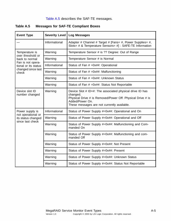
MegaRAID Service Monitor Event Types A-5Version 1.0 Copyright © 2003 by LSI Logic Corporation. All rights reserved.
Table A.5 describes the SAF-TE messages.
Table A.5 Messages for SAF-TE Compliant Boxes
Event Type Severity Level Log Messages
— Informational Adapter # Channel # Target # [Fans= #, Power Supplies= #,Slots= # & Temperature Sensors= #] : SAFE-TE Information
Temperature isover threshold orback to normalFan is not opera-tional or its statuschanged since lastcheck
Warning Temperature Sensor # is ?? Degree: Out of Range
Warning Temperature Sensor # is Normal
Informational Status of Fan # =0x##: Operational
Warning Status of Fan # =0x##: Malfunctioning
Warning Status of Fan # =0x##: Unknown Status
Warning Status of Fan # =0x##: Status Not Reportable
Device slot IDnumber changed
Warning Device Slot # ID=#: The associated physical drive ID haschanged.Physical Drive # is Removed/Power Off. Physical Drive # isAdded/Power On.These messages are not currently available.
Power supply isnot operational orits status changedsince last check
Informational Status of Power Supply #=0x##: Operational and On
Warning Status of Power Supply #=0x##: Operational and Off
Warning Status of Power Supply #=0x##: Malfunctioning and Com-manded On
Warning Status of Power Supply #=0x##: Malfunctioning and com-manded Off
Warning Status of Power Supply #=0x##: Not Present
Warning Status of Power Supply #=0x##: Present
Warning Status of Power Supply #=0x##: Unknown Status
Warning Status of Power Supply #=0x##: Status Not Reportable

A-6 MegaRAID Service MonitorVersion 1.0 Copyright © 2003 by LSI Logic Corporation. All rights reserved.
Table A.6 describes the battery status messages.
Table A.6 Battery Status Messages
Event Type Severity Level Log Messages
Battery backup, mod-ule/pack, missing or added
Warning Battery Backup Module is Missing
Warning Battery Backup Module present but Battery BackupPack is Missing
Informational Battery Backup/Pack present
Battery temperature out ofrange or back to normal
Warning Battery Temperature OUT OF RANGE
Informational Battery Temperature GOOD
Battery voltage low ornormal
Warning Battery Voltage LOW
Informational Battery Voltage GOOD
Battery fast charging inprogress/failed/completed
Warning Battery Fast Charging IN PROGRESS.
Warning Battery Fast Charging FAILED.
Informational Battery Fast Charging COMPLETED.
Number of battery chargecycles
Informational “No of Charge Cycles = ??”
Since the monitor programscans the bus periodically, itchecks for devices and com-pares with the previousresults. If not a match, it logsmessages.
Warning Physical drive is Removed/Powered Off.
Warning Physical drive is Added/Powered On. The PowerOn/Off feature is not implemented in the currentversion.

Event Message IDs A-7Version 1.0 Copyright © 2003 by LSI Logic Corporation. All rights reserved.
A.3 Event Message IDs
Each event log message has its unique ID number. For general events,the event message ID is three digits. Table A.7 describes the generalevents log message.
For test-related events, the event message ID is four digits. Table A.8describes the test-related event message
Table A.7 General Event Message IDs
ID Field Definition
First digit Test Type ID Status:1 Logical Drive Status2 Physical Drive Status3 Physical Drive Error Count
Last two digits Two-digit event code
Table A.8 Test-Related Event Message IDs
ID Field Definition
First digit Test Type ID Status:1 Logical Drive Status2 Physical Drive Status3 Physical Drive Error Count
Second digit Severity Level:1 Informational2 Warning3 Error
Last two digits Two-digit event code

A-8 MegaRAID Service MonitorVersion 1.0 Copyright © 2003 by LSI Logic Corporation. All rights reserved.

MegaRAID Configuration Software User’s Guide IX-1Version 1.0 Copyright © 2003 by LSI Logic Corporation. All rights reserved.
Index
A
abort rebuild 5-15accept array 5-20activate channel 4-8adapter 4-6, 5-11adapter BIOS 3-5adapter information 2-5adapter menu 5-14
Configuration Utility 2-4adapter properties icon 5-12adapter properties screen 3-4adapter selection 2-10, 3-4adapter status 5-15adapter type 4-7adaptive 2-15, 3-8, 4-15adaptive cache 2-7adaptive read ahead 5-17add capacity 5-16add drives 5-16add spare 5-20add to array 5-20adding capacity to disk administrator 6-4adding physical drives 5-24alarm control 2-5, 4-7, 5-14array
configuration guidelines 4-4configurations 5-6reconfiguring 5-24span 5-21undo configuration 5-19, 5-21, 5-24, 5-25
assigning hot spares 5-21auto configuration 4-3, 4-4, 4-12
default settings 4-4auto rebuild 2-5, 3-5auto termination 2-8automatic configuration 5-13, 5-19
B
backup module 2-9, 4-9batch initialization 2-16, 4-16batch rebuild 2-17, 4-17battery backup 2-9, 4-6, 4-9battery backup submenu 2-9battery charge cycles 2-9, 4-9battery fast charging 2-9, 4-9battery pack 2-9, 4-9battery pack life 2-9, 4-9binary file 5-23BIOS 2-5
force boot 2-5version 3-5
bus termination 2-8, 4-8
C
cacheadaptive 2-7normal 2-7policy 2-7, 5-16read-ahead 2-7, 2-15, 5-16ready policy 5-17write policy 3-8, 5-16write-back 2-7, 3-8write-through 2-7, 3-8
cache flush timings 2-5cache memory size 4-7cache policy default setting 4-5cache write-back 5-16, 5-17cache write-through 5-16, 5-17cached I/O 2-7, 5-16CanSpan 2-15, 4-15capacity 5-16
adding 5-25expansion 6-1
change configuration 5-16change status 5-15change status menu 5-15channel 4-6, 4-8charge cycles 2-9, 4-9check consistency 2-6, 2-10, 3-6, 4-7, 4-10, 5-16chip set type 2-5choosing a configuration method 4-11class emulation mode 3-5clear configuration 2-3, 2-5, 4-4, 4-7, 5-13clear configuration icon 5-12client 5-6
requirements 5-3coercion algorithm 2-6command tagging 2-8configurating drives 2-14, 4-14configuration 5-13
automatic 5-19change 5-16custom 5-20guidelines 4-4mismatch 3-6preview 3-8save 5-23undo 5-19, 5-21, 5-24, 5-25
configuration menu 5-13

IX-2Version 1.0 Copyright © 2003 by LSI Logic Corporation. All rights reserved.
configuration mismatch screen 3-6configuration on disk 2-17configuration steps 2-1, 4-1, 5-1
power console plus 5-18WebBIOS 3-2
detailed 3-7Configuration Utility 2-1
adapter menu 2-4alarm control 2-5auto rebuild 2-5backup module 2-9battery backup submenu 2-9battery pack 2-9cache flush timing 2-5cache policy 2-7check consistency 2-6, 2-10chip set type 2-5choosing a configuration method 2-11clear configuration 2-3, 2-5coercion algorithm 2-6configuration steps 2-1configure menu 2-3configuring drives 2-12description 1-1designating hot spare drives 2-12disable BIOS 2-5disk spin-up timing 2-5drive information 2-8drive state 2-7easy configuration 2-3, 2-12emulation 2-5enable auto termination 2-8exiting 2-19factory default 2-5fail drive 2-8fast charging 2-9fast initialization 2-5FlexRAID powerfail 2-5FlexRAID virtual sizing 2-7force boot 2-5format 2-8, 2-9hot keys 2-11I/O policy 2-6individual rebuild 2-18initialize menu 2-4initialize option 2-6initializing drives 2-16initializing logical drives 2-4initiator ID 2-5logical drive configuration screen 2-13logical drive submenu 2-6make hot spare 2-8make online 2-8menu tree 2-2new configuration 2-3, 2-14number of cycles 2-9objects menu 2-4, 2-6other adapter information 2-5PCI delayed transactions 2-5physical drive menu 2-8read policy 2-6read-ahead policy 2-7rebuild drive 2-8rebuild drives 2-10rebuild rate 2-5rebuilding drives 2-17
reserved drive space 2-3SCSI channel submenu 2-8SCSI command tagging 2-8SCSI transfer rate 2-8select adapter 2-10specify bootable logical disk 2-3starting 2-11steps for configuring drives 2-11stripe size 2-7synchronous negotiation 2-8temperature 2-9termination state 2-8view/add configuration 2-3, 2-14view/update parameters 2-6virtual sizing 2-6voltage monitor 2-9write policy 2-6, 2-7
configuration wizard 3-7, 5-13, 5-20configure menu 2-3, 4-3configuring drives
Configuration Utility 2-12easy configuration 2-12, 4-13MegaRAID Manager 4-10Power Console Plus 5-18view/add configuration 2-14, 4-14
create new configuration 3-6ctrl-M 2-11custom configuration 5-13, 5-20
D
data rate 2-8default auto configuration settings 4-4defining logical drives 5-21delay PCI transfer 3-5delayed transactions 2-5de-registering under Power Console Plus 5-10designating hot spare drives 2-12, 4-11device 5-11diagnostics 5-14direct I/O 2-5, 2-7, 5-16disable BIOS 2-5disable termination 4-9disk administrator 6-4disk spin-up timings 2-5, 4-7display
Power Console Plus 5-13display configuration icon 5-12display log icon 5-12display the logical drive configuration 2-11, 4-10display the logical drives 2-11, 4-10display the manufacturer data 2-11, 4-10drive
adding 5-16capacity expansion 6-1choosing a configuration method 2-11configuration steps using the Configuration Utility 2-11fail 4-8formatting 2-8hot spare 2-8, 2-12, 4-8, 4-11, 5-15information 2-8initializing 2-16, 4-6, 4-7, 4-16, 5-23logical drive size 2-15, 4-15pre-laoded 2-18properties icon 5-12rebuilding 2-8, 2-17, 4-17

IX-3Version 1.0 Copyright © 2003 by LSI Logic Corporation. All rights reserved.
reserved space 2-3roaming 2-17spanning 2-15, 4-15spin down 5-15spin up interval 5-15state change 2-8states 5-18status 4-8view information 4-8
drive indicator 5-18FAILED 5-18HOTSP 2-12, 4-12, 5-18ONLIN 2-13, 4-13ONLN 5-18READY 2-12, 4-12REBLD 2-17, 2-18, 4-17
drive information 2-8drive menu 5-15drive state 2-7
failed 5-18hot spare 5-18online 5-18ready 5-18rebuilding 5-18
E
easy configuration 2-3, 2-12, 4-3, 4-5, 4-13emulation 2-5, 3-5enable auto termination 2-8enclosure management 5-14event log 5-14event message IDs A-7event types A-3, A-7event viewer 5-4exit 5-13exit icon 5-13exiting
Configuration Utility 2-19MegaRAID Manger 4-18
extend volume set 6-4
F
F10 2-11, 4-10F2 2-11, 4-10F3 2-11, 4-10F4 2-11, 4-10factory default 3-5factory default option 2-5fail drive 2-8, 4-8, 5-15FAILED 5-18fan temperature 5-14fast charging 2-9, 4-9fast initialization 2-5, 5-14features
Power Console Plus 5-3firmware 5-15firmware version 3-5, 4-7FlexRAID 2-5, 3-5, 4-7, 5-3, 5-22FlexRAID virtual sizing 2-7flush cache 5-14force boot 2-5format 2-8format option 2-9
G
groups 5-9guidelines for configuration 4-4
H
help icon 5-13HOSTS.DAT 5-5, 5-7hot keys 2-11, 4-10hot spare 2-11, 2-17, 4-8, 4-10, 4-11, 4-17, 5-15, 5-18, 5-24
assigning 5-21hot spare drive 2-8hot spare drives
designating 2-12HOTSP 2-12, 4-12, 5-18
I
I/Obuffered 2-7cached 2-7, 5-16direct 2-7, 5-16policy 2-6
I2O 2-5, 3-5icons 5-12ID 2-5individual initialization 2-16, 4-16individual rebuild 2-18, 4-17initialization 5-14
batch 2-16, 4-16initialize 2-6, 4-7
drives 2-4logical drive 5-23
initialize drive 2-16, 4-16initialize logical drive 5-16initialize option 2-4, 4-6initiator ID 2-5installation
configurations 5-6MegaService Monitor 5-10overview of Power Console Plus 5-5Power Console Plus 5-4, 5-6Power Console Plus SNMP agent 5-9Windows SNMP agent 5-7
installation packages 5-6
L
load 5-13log icon 5-12logical device 5-11logical drive 2-13, 4-6, 4-7logical drive configuration screen 2-11, 2-13, 4-10, 4-13logical drive display 2-11, 4-10logical drive menu 5-16logical drive properties icon 5-12logical drive screen 3-5logical drive size 2-15, 3-8, 4-15logical drive submenu 2-6logical drives
defining 5-21initializing 2-4, 2-6, 3-6
logical view 3-4

IX-4Version 1.0 Copyright © 2003 by LSI Logic Corporation. All rights reserved.
M
main menuMegaRAID Manager 4-3
main screen 3-4make hot spare 2-8, 2-11, 4-8, 4-10, 4-12, 5-15make online 2-8, 4-8, 5-15manufacturer data 2-11, 4-10mass storage 2-5, 3-5MEGACONF 4-11MegaRAID Client 5-6MegaRAID Manager 4-1, 4-6, 4-11
activate channel 4-8adapter submenu 4-6adapter type 4-7advanced menu 4-10alarm control 4-7auto configuration 4-3, 4-4, 4-12backup module 4-9battery backup 4-6, 4-9battery pack 4-9channel 4-6, 4-8check consistency 4-7check consistency option 4-10choosing a configuration method 4-11clear configuration 4-4, 4-7configuration steps 4-1configure menu 4-3configuring drives 4-10description 1-2designating hot spare drives 4-11disable termination 4-9disk spin-up timings 4-7drive information 4-8easy configuration 4-3, 4-5, 4-13exiting 4-18fail drive 4-8fast charging 4-9FlexRAID PowerFail 4-7initialize option 4-7initializing drives 4-16logical drive 4-6, 4-7logical drive configuration screen 4-13main menu 4-3make hot spare 4-8make online 4-8menu tree 4-2new configuration 4-4, 4-5, 4-14number of cycles 4-9objects menu 4-6physical drive 4-6, 4-8rebuild 4-8rebuild option 4-9rebuild progress 4-8reconstruct logical drive 4-10starting 4-11temperature 4-9terminate high 8 bits 4-8terminate wide channel 4-8termination status 4-8view adapter performance 4-7view drive information 4-8view properties 4-9view rebuild progress 4-8view/add configuration 4-4, 4-5, 4-14view/update parameters 4-7
view/update properties 4-7voltage monitor 4-9
MegaRAID Mangerhot keys 4-10individual rebuild 4-17
MegaRAID Server 5-2, 5-6MegaRAID service monitor A-1MEGARAID.LOG 5-4, A-1MegaRAID.SYS driver 6-1MEGASERV.EXE 5-4MegaService Client 5-2MegaService Monitor 5-4, 5-5, 5-10menu bar 5-11menu tree
Configuration Utility 2-2MegaRAID Manager 4-2
monitorMegaService Monitor 5-10performance 5-14
multiple PCI delayed transactions 2-5
N
narrow SCSI bus 4-8NetWare
cache policy 5-17virtual sizing 6-4
new configuration 2-3, 2-14, 4-4, 4-5, 4-14non-volatile RAM 2-17normal 5-17normal caching 2-7NoSpan 2-15, 4-15number of cycles 2-9, 4-9number of drives 2-12, 4-12NVRAM 2-17
O
objects menu 2-4, 4-6Configuration Utility 2-6
ONLIN 2-13, 4-13online 5-18online capacity expansion 6-1online physical drive 5-15ONLN 5-18operating system support 1-3
Power Console Plus 5-2other adapter information 2-5
P
packages 5-6parameters
update 2-6PCI delayed transactions 2-5, 3-5performance monitor 5-14permissions 5-9physical device 5-11physical drive 4-6, 4-8
adding 5-24removing 5-25
physical drive menuConfiguration Utility 2-8Power Console Plus 5-15
physical drive properties 5-15

IX-5Version 1.0 Copyright © 2003 by LSI Logic Corporation. All rights reserved.
physical drive properties icon 5-12physical drive status 5-15physical drives screen 3-6physical view 3-4policy
cache 2-6, 2-7I/O 2-6read 2-6write 2-6, 2-7, 3-8
Power Console Plus 6-3abort rebuild 5-15accept array 5-20adapter 5-11adapter menu 5-14adapter properties icon 5-12adapter selection 5-19add capacity 5-16add spare 5-20add to array 5-20adding capacity 6-3adding physical drives 5-24alarm control 5-14arrays 5-24automatic configuration 5-19cache policy 5-16capacity 5-16change configuration 5-16change status 5-15change status menu 5-15check consistency 5-16check rebuild rate 5-24choosing an adapter 5-19clear configuration 5-13clear configuration icon 5-12client system requirements 5-3components 5-2configuration 5-13configuration menu 5-13configuration steps
quick 5-1configuration wizard 5-19, 5-20configurations 5-6configuring drives 5-18custom configuration 5-20defining logical drives 5-21de-registering 5-10description 1-2, 5-11detailed installation 5-6device 5-11diagnostics 5-14display 5-13display configuration icon 5-12display log icon 5-12drive spin up 5-15enclosure management 5-14event viewer 5-4exit 5-13exit icon 5-13fail drive 5-15fast initialization 5-14features 5-3firmware update 5-15flush cache 5-14group setup 5-9help icon 5-13hot spare 5-21, 5-24
icons 5-12initialization 5-14initialize drives 5-23initialize logical drive 5-16installation packages 5-6installation requirements 5-4interface description 5-11internal messages A-1load 5-13log icon 5-12logical device 5-11logical drive menu 5-16logical drive properties icon 5-12main window 5-11make hot spare 5-15make online 5-15MegaRAID Client 5-6MegaRAID Server 5-2, 5-6MegaService Client 5-2MegaService Monitor 5-4menu bar 5-11menus 5-13operating system support 5-2overview of installation 5-5performance monitor 5-14permissions 5-9physical device 5-11physical drive menu 5-15physical drive properties icon 5-12print 5-13print icon 5-12progress menu 5-17properties 5-14, 5-15, 5-16quick configuration steps 5-1RAID level 5-16read policy 5-16, 5-17rebuild 5-15rebuild rate 5-14, 5-24rebuild rate icon 5-12reclaim 5-19, 5-20, 5-21, 5-24, 5-25reconfiguring arrays 5-24registering 5-10Registration Server 5-2, 5-6removing a physical drive 5-21, 5-25rescan 5-14rescan icon 5-12restrictions 5-11running the configuration wizard 5-19save 5-13save configuration 5-23scan icon 5-12securing 5-9Service Monitor 5-2, 5-3silence alarm 5-14SNMP agent 5-2, 5-9span array 5-21spin down 5-15spin up interval 5-15start screen 5-11starting 5-18status bar 5-11toolbar 5-11update firmware 5-14, 5-15view 5-11view log 5-14virtual sizing 5-16

IX-6Version 1.0 Copyright © 2003 by LSI Logic Corporation. All rights reserved.
window 5-11Windows installation 5-4wizard 5-13wizard icon 5-12write policy 5-16
power console plusconfiguration steps 5-18
powerfail 2-5pre-loaded drive 2-18print 5-13print icon 5-12properties 3-6, 5-14, 5-15, 5-16
Q
quick configuration stepsConfiguration Utility 2-1MegaRAID Manager 4-1Power Console Plus 5-1WebBIOS 3-2
R
RAID 0 number of drives 2-12, 4-12RAID 1 number of drives 2-12, 4-12RAID 5 number of drives 2-12, 4-12RAID level 5-16, 5-22RAID storage adapter 1-vRAID.LOG A-1RAM size 3-5read ahead 5-17read policy 2-6, 5-16, 5-17
default setting 4-5read-ahead 2-15, 3-7, 4-15, 5-16
cache 2-7READY 2-12, 4-12, 5-18REBLD 2-17, 2-18, 4-17REBUILD 5-18rebuild 2-8, 4-8, 5-15rebuild abort 5-15rebuild drives 2-10rebuild option 4-9rebuild progress 4-8rebuild rate 2-5, 3-5, 5-14, 5-24rebuild rate icon 5-12rebuilding drives 2-17, 5-18rebuilding drivesMegaRAID Manager
rebuilding drives 4-17reclaim 5-20reclaim array 5-19, 5-21, 5-24, 5-25reconfiguring arrays 5-24reconstruct logical drive
advanced menu 4-10redundancy
verify 2-6, 5-16registering under Power Console Plus 5-10Registration Server 5-2, 5-5, 5-6REGSERV.DAT 5-5, 5-7removing a physical drive 5-21, 5-25requirement
Power Console Plus installation 5-4rescan 5-14rescan icon 5-12reserved disk space 2-3restrictions for Power Console Plus 5-11roaming 2-17
RSA 1-vrunning Power Console Plus 5-11
S
SAFTE 5-14save 5-13save configuration 5-23scan devices 3-4scan icon 5-12SCSI
bus termination 2-8, 4-8channel submenu 2-8command tagging 2-8narrow bus 4-8transfer rate 2-8wide bus 4-8
securing Power Console Plus 5-9select adapter menu 2-10server 5-2, 5-6service monitor 5-2, 5-3, A-1
event types A-3service packs 5-4set factory defaults 3-5silence alarm 5-14size
logical drive 2-15, 4-15SNMP agent
Power Console Plus 5-2, 5-5, 5-9Windows 5-5, 5-7
span array 5-21spannable drives 2-15, 4-15spanning default setting 4-5spanning mode 2-14, 3-8, 4-15specify bootable logical disk 2-3spin down 5-15spin up interval 5-15starting
Configuration Utility 2-11MegaRAID Manager 4-11Power Console Plus 5-18WebBIOS 3-2
statusdrive 4-8
status bar 5-11stop rebuild 5-15stripe size 2-7, 2-15, 3-7, 4-15stripe size default setting 4-5supported operating systems 1-3, 4-11
MegaRAID Manager 4-11Power Console Plus 5-2
synchronous negotiation 2-8system requirements 5-3
T
tagging 2-8TCP/IP 5-4, 5-7temperature 2-9, 4-9, 5-14terminate high 8 bits 4-8terminate wide channel 4-8termination 2-8
state 2-8status 4-8
timingcache flush 2-5

IX-7Version 1.0 Copyright © 2003 by LSI Logic Corporation. All rights reserved.
disk spin-up 2-5, 4-7toolbar 5-11toolbar options 3-3transfer rate 2-8
U
undoing the array 5-19, 5-21, 5-24, 5-25update drive firmware 5-15update firmware 5-14
V
verify redundancy 2-6, 3-6, 4-7, 4-10, 5-16view 5-11view adapter performance 4-7view disk configuration 3-6view drive information 4-8view log 5-14view NVRAM configuration 3-7view properties 4-9view rebuild progress 4-8view/add configuration 2-3, 2-14, 4-4, 4-5, 4-14view/update parameters 2-6, 4-7view/update properties 4-7virtual sizing 2-6, 2-7, 5-16, 6-1, 6-3
enabling 6-3NetWare 6-4theory of operation 6-1Windows 6-2
voltage levels 5-14voltage monitor 2-9, 4-9
W
WebBIOS 3-1adapter BIOS 3-5adapter properties screen 3-4adapter selection 3-4adaptive 3-8auto rebuild 3-5BIOS version 3-5check consistency 3-6class emulation mode 3-5configuration mismatch screen 3-6configuration preview 3-8configuration steps 3-7configuration wizard 3-7create new configuration 3-6description 1-2firmware version 3-5FlexRAID PowerFail 3-5initializing logical drives 3-6logical drive size 3-8logical drives screen 3-5logical view 3-4main screen 3-4PCI delay transfer 3-5physical drives screen 3-6physical view 3-4properties 3-6quick configuration steps 3-2RAM size 3-5read-ahead 3-7rebuild rate 3-5
scan devices 3-4set factory default 3-5spanning 3-8starting 3-2toolbar options 3-3view disk configuration 3-6view NVRAM configuration 3-7write policy 3-8write-back cache 3-8write-through cache 3-8
wide termination 4-8Windows 1-3
Power Console Plus installation 5-4SNMP agent 5-7virtual sizing 6-2
wizard icon 5-12write policy 2-6, 2-7, 3-8, 5-16write policy default setting 4-5write-back cache 2-7, 3-8, 5-16, 5-17write-through cache 2-7, 3-8, 5-16, 5-17

IX-8Version 1.0 Copyright © 2003 by LSI Logic Corporation. All rights reserved.

MegaRAID Configuration Software User’s GuideVersion 1.0 Copyright © 2003 by LSI Logic Corporation. All rights reserved.
Customer Feedback
We would appreciate your feedback on this document. Please copy thefollowing page, add your comments, and fax it to us at the numbershown.
If appropriate, please also fax copies of any marked-up pages from thisdocument.
Important: Please include your name, phone number, fax number, andcompany address so that we may contact you directly forclarification or additional information.
Thank you for your help in improving the quality of our documents.

Customer FeedbackVersion 1.0 Copyright © 2003 by LSI Logic Corporation. All rights reserved.
Reader’s Comments
Fax your comments to: LSI Logic CorporationTechnical PublicationsM/S E-198Fax: 408.433.4333
Please tell us how you rate this document: MegaRAID ConfigurationSoftware User’s Guide. Place a check mark in the appropriate blank foreach category.
What could we do to improve this document?
If you found errors in this document, please specify the error and pagenumber. If appropriate, please fax a marked-up copy of the page(s).
Please complete the information below so that we may contact youdirectly for clarification or additional information.
Excellent Good Average Fair Poor
Completeness of information ____ ____ ____ ____ ____Clarity of information ____ ____ ____ ____ ____Ease of finding information ____ ____ ____ ____ ____Technical content ____ ____ ____ ____ ____Usefulness of examples andillustrations
____ ____ ____ ____ ____
Overall manual ____ ____ ____ ____ ____
Name Date
Telephone
Title
Company Name
Street
City, State, Zip
Department Mail Stop
Fax