userÕs guide cn8-swcn8-swÔ userÕs guide 1-4 1.1.6 local alarms if a controller that supports the...
TRANSCRIPT

UserÕs Guide
CN8-SW
OMEGA #M3350/0101

900M048U00 REVISION ÒBÓ Ó Omega Engineering i
Table of Contents1. Introduction...............................................................................................1-1
1.1 Features..................................................................................................................1-1
1.1.1 Transforms a PC into an Operator Station ....................................................1-1
1.1.2 Graphical Interface..........................................................................................1-2
1.1.3 Automated Ramp and Soak Cycles ...............................................................1-3
1.1.4 Logging............................................................................................................1-3
1.1.5 Storing and Loading Configuration Parameter Sets......................................1-3
1.1.6 Local Alarms....................................................................................................1-4
1.2 Hardware and Software Requirements .................................................................1-4
1.2.1 CN8-SW Computer .........................................................................................1-4
1.2.2 Controllers .......................................................................................................1-4
1.3 Overview of Setup Tasks .......................................................................................1-5
1.4 Overview of CN8-SW Menus.................................................................................1-7
1.4.1 Availability of Functions ..................................................................................1-7
1.4.2 Menu Convention Used in This Manual.......................................................1-11
1.5 General Instructions for Using CN8-SW Windows .............................................1-11
2. Wiring the Network and Connecting the Computer.................................2-12.1 Introduction .............................................................................................................2-1
2.2 Connecting Controllers and the Computer to the Network...................................2-2
2.2.1 Introduction......................................................................................................2-2
2.2.2 RS-232 Interface.............................................................................................2-2
2.2.3 RS-485 Network..............................................................................................2-3
3. Installing the Software and Logging In ...................................................3-13.1 Installing the Software............................................................................................3-1
3.2 Starting the Software..............................................................................................3-3
3.3 Logging In to CN8-SW Using the Default Account ...............................................3-4
3.4 Changing the Password for the Default Account ..................................................3-5
3.5 Setting Up Operator Accounts ...............................................................................3-6
3.5.1 Permissions Available.....................................................................................3-6
3.5.2 Procedure........................................................................................................3-7
3.6 Editing an Operator Account..................................................................................3-8
3.7 Deleting an Operator Account ...............................................................................3-8
3.8 Logging Out of the CN8-SW Application...............................................................3-8
4. Establishing Communication with Controllers........................................4-14.1 Introduction .............................................................................................................4-1
4.2 Configuring Communication Parameters and Assigning Network Addresses inControllers ..........................................................................................................................4-2

CN8-SWÔ UserÕs Guide
ii Ó Omega Engineering 900M048U00 REVISION ÒBÓ
4.2.1 Communication Parameters...........................................................................4-2
4.2.2 Network Addresses.........................................................................................4-3
4.3 Configuring Communication Parameters for CN8-SW System............................4-4
4.4 Recognizing Controllers with the CN8-SW Software............................................4-6
4.4.1 Introduction......................................................................................................4-6
4.4.2 Automatically Using the Find Controllers Option...........................................4-6
4.4.3 Manually Using the Controller Menu............................................................4-10
4.5 Deleting a Controller.............................................................................................4-11
4.6 Changing Baud Rate after Communication Has Been Established...................4-12
4.7 Naming Controllers...............................................................................................4-14
4.8 Saving the .MCS File............................................................................................4-14
4.9 Closing an .MCS File............................................................................................4-14
4.10 Creating a New .MCS File ...................................................................................4-14
4.11 Opening an Existing .MCS File............................................................................4-15
5. Configuring Local Alarms.........................................................................5-15.1 Introduction .............................................................................................................5-1
5.2 Procedure ...............................................................................................................5-1
6. Viewing Process Values and Changing Setpoint ...................................6-16.1 Introduction .............................................................................................................6-1
6.2 Viewing PV and SP in the Main Window...............................................................6-2
6.3 Viewing PV and SP in a Graph..............................................................................6-3
6.4 Changing the Setpoint Using the Setpoint Dialog Box .........................................6-4
6.5 Configuring and Invoking the Single-Step Ramp Function ..................................6-5
7. Changing Controller Mode and Using Autotune......................................7-17.1 Introduction .............................................................................................................7-1
7.2 Procedure ...............................................................................................................7-1
8. Viewing and Changing Controller Configuration Parameters.................8-18.1 Introduction .............................................................................................................8-1
8.2 Accessing Configuration Parameter Displays.....................................................8-12
8.3 Using Configuration Parameter Displays ..............................................................8-3
9. Configuring and Running Ramp and Soak Recipes ................................9-19.1 Introduction .............................................................................................................9-1
9.2 Configuring CN8-SW Recipes ...............................................................................9-2
9.2.1 Creating a New Recipe...................................................................................9-2
9.2.2 Editing an Existing Recipe..............................................................................9-4
9.3 Running CN8-SW Recipes ....................................................................................9-5
9.3.1 Starting to Run a Recipe ................................................................................9-5
9.3.2 Holding (Pausing) Recipe Execution .............................................................9-6
9.3.3 Resuming Recipe Execution ..........................................................................9-7
9.3.4 Stopping Recipe Execution ............................................................................9-8
9.4 Configuring Controller Ramp and Soak Parameters ............................................9-9
9.5 Running Controller Ramp and Soak Cycles .......................................................9-12
10. Storing and Loading Controller Configurations.................................10-1

Table of Contents
900M048U00 REVISION ÒBÓ Ó Omega Engineering iii
10.1 Introduction ...........................................................................................................10-1
10.2 Storing Configuration............................................................................................10-2
10.3 Loading Configuration ..........................................................................................10-4
11. Logging PV and SP Values..................................................................11-111.1 Introduction ...........................................................................................................11-1
11.2 Turning On the Logging Function ........................................................................11-1
11.3 Viewing and Printing Log Files ............................................................................11-2
11.4 Turning Off the Logging Function ........................................................................11-2
12. Index.....................................................................................................12-1Limited Warranty................................................................. Error! Bookmark not defined.

CN8-SWÔ UserÕs Guide
iv Ó Omega Engineering 900M048U00 REVISION ÒBÓ

1-1
1. Introduction
1.1 Features
1.1.1 Transforms a PC into an Operator Station
The CN8-SW software makes it easy for operators to use a personal computer to monitornetworked Omega controllers. Linked to the controllers by an RS-485 network, the PCcan be used to read process values, change setpoints and other parameters, changecontroller mode, and monitor for alarms.1 CN8-SW is also ideal for quickly configuring asingle controller in a lab or service department, using an RS-232 link.
The CN8-SW application can communicate with any Omega controller that supports theOmega Plus Protocol or the original Omega Protocol. All the configuration parametervalues stored in non-volatile memory in a controller that supports Omega Plus Protocolcan be saved to the PC for backup, and loaded to the same or different controllers.
1 Up to 32 controllers can be included on an RS-485 network without using a network repeater device.The CN8-SW software can address up to 254 controllers.

CN8-SWÔ UserÕs Guide
1-2
1.1.2 Graphical Interface
The CN8-SW software uses a graphical user interface and familiar point-and-clicktechniques. The main CN8-SW display shows PV and SP of every controller. The CN8-SW system can be set up to show all controllers on the network on a single display, oronly selected controllers. Any message that can be displayed on a controllerÕs frontpanel will also be shown on the CN8-SW display. Operators can see at a glance if acontroller is in standby or other special mode, and if the controller detects a problem suchas an open sensor.
Double-clicking (left button) on any controller in the main display will call up a display ofall the parameters in Omega Plus Protocol-compliant controllers, and the most importantparameters in controllers that support the original Omega Protocol. A right-click on acontroller displays the form used to change its setpoint. A left-click on a controller selectsthe controller for functions on the Controller menu. Many additional functions areaccessible using the other CN8-SW menus.
A Òtext onlyÓ view is available for operators who prefer to see the controller setpoints andprocess variables in list form. A left-click on a controller in the list selects the controllerfor functions on the Controller menu.

Introduction
1-3
1.1.3 Automated Ramp and Soak Cycles
Use the CN8-SW Ramp and Soak function to configure any number of recipes consistingof any number of ramp and soak steps. These recipes are stored on the CN8-SWcomputer. Under the direction of CN8-SW, any controller on the network can executeyour choice of recipe, even models that do not support configuration and execution oframp and soak cycles using the controller front panel.
The CN8-SW displays also provide a quick way to configure and run recipes that use thecontrollerÕs own recipe parameters.
1.1.4 Logging
The CN8-SW application supports optional logging of SP and PV for all controllers atconfigurable intervals. Logs are saved in ASCII text files with comma-separated-valueformat. These files can be viewed, printed, and manipulated with other applications, suchas word processing and spreadsheet software.
1.1.5 Storing and Loading Configuration Parameter Sets
All the configuration parameter values stored in non-volatile memory in a controller thatsupports Omega Plus Protocol can be saved to the PC and loaded to the same ordifferent controllers. Backing up a unique controller configuration on a PC is alwaysprudent. If a controller is damaged later and must be replaced, its custom configurationcan be loaded quickly to a spare controller, minimizing down time.
In large installations where many controllers use the same (or almost the same)configuration, its easy to configure one controller using the CN8-SW display, save theparameter set to the PC, then load the same parameter set to many other controllers onthe network. The time saved by eliminating the need to configure each controller at itsfront panel more than pays for the CN8-SW package.
The ability to store and load a controller configuration also enables you to reuse tuningparameter values that have proved to be best for certain process conditions. If theresponsiveness of your process is altered at times, you may find it desirable to save setsof tuning parameters to be used under different circumstances.
For example, if you autotune the controller for optimum control of the temperature of anengraving cylinder while one size is in use, save the parameter set before installing alarger or smaller cylinder. The different size cylinder may heat at a different rate,requiring different tuning parameters to be used for optimum control. Save the newtuning as a parameter set with a different name. When the day comes that you have toreinstall the first cylinder, reload the parameter set, including the tuning parameters thatwere optimized for that cylinder.

CN8-SWÔ UserÕs Guide
1-4
1.1.6 Local Alarms
If a controller that supports the Omega Plus Protocol is in alarm, the A1 or A2 indicatoron the controllerÕs Òfront panelÓ on the main display will appear to be lit (red), matchingthe behavior of the A1 and A2 indicators on the controller faceplate. The process valueon the CN8-SW graphic display will also change color from magenta (normal) to red(alarm).
As a bonus, the CN8-SW supports Òlocal alarmsÓ. These two process alarms can beconfigured in CN8-SW for each controller on the network, including controllers that do notprovide an alarm function of their own, and controllers that support the original OmegaProtocol.2 If a controllerÕs PV exceeds (high alarm) or falls below (low alarm) theconfigured local alarm limit, the alarm indicators on the main graphic display will ÒlightÓand the PV will change to red.
1.2 Hardware and Software Requirements
1.2.1 CN8-SW Computer
The computer used to run the CN8-SW software must meet the following requirements:
· 4 8 6 S X o r b e t t e r p r o c e s s o r
· 1 M B o f d i s k s p a c e f o r C N 8 - S W s o f t w a r e ( p l u s a d d i t i o n a l s p a c e f o r l o g f i l e s )
· W i n d o w s 9 5 o r W i n d o w s 9 8
· Available COM (serial) port or RS-485 port. Communication between the PC and anRS-485 network can be accomplished using a COM port and an RS-232-to-RS-485converter. Communication with a single controller using a COM port for an RS-232link does not require a converter, but does require an adapter.
1.2.2 Controllers
Any controller that uses the Omega Plus Protocol, and has an appropriatecommunication option card can communicate with the CN8-SW computer.
· O n e - t o - o n e c o m m u n i c a t i o n w i t h t h e C N 8 - S W c o m p u t e r r e q u i r e s a n R S - 2 3 2 o r R S - 4 8 5 c a r d .
· T o b e p a r t o f a m u l t i - d r o p n e t w o r k , t h e c o n t r o l l e r m u s t h a v e a n R S - 4 8 5 o p t i o n c a r d i n s t a l l e d .
2 At the time of publication, the following controllers support the Omega Plus Protocol: Series CN8500(1/16 DIN, 1/8 DIN and _ DIN). If you have a question about the protocol supported by a new model,please call your Omega sales / service representative at: 1-800-826-6342 in the U.S.A. and Canada and(95) 800-TC-OMEGASM in Mexico and Latin America.

Introduction
1-5
1.3 Overview of Setup TasksThe following tasks must be performed in this sequence to use the CN8-SW applicationsuccessfully with an RS-485 network. The same basic process applies to using the CN8-SW application to communicate with a single controller over anRS-232 link. In the case of RS-232 links, the ÒnetworkÓ consists of only the controller andthe PC.
S t e p T a s k S e c t i o n i n t h i s M a n u a l
1 Connect the controllers to the network. 2and controller
manuals
2 Connect the personal computer to the network. 2
3 Install the CN8-SW software and log in. 3
4 Change the password on the default account ÒMULTIÓ (not required, butstrongly recommended).
3
5 Set up operator accounts and assign passwords. 3
6 If any of the Omega Plus controllersÕ communication parameters have beenchanged from the factory defaults, use the front panel of each controller toset each controllerÕs configuration parameters to the defaults.
4and controller
manuals
7 For controllers that support the original Omega Protocol, use eachinstrumentÕs front panel to set the controller to use 8 data bits, no parity,1 stop bit. Configure each controller to match the baud rate you plan to usefor the network. If you plan to use the automatic Òfind controllersÓ optiondescribed in Step 11, set the Omega Protocol controllers to 9600 baud.
4and controller
manuals
8 Use the front panel of all controllers (Omega Protocol and Omega PlusProtocol) to assign a unique address (between 1 and 254) to each controller.
4and controller
manuals
9 Configure the CN8-SW communication parameters and port selection. (TheCN8-SW communication settings will override, but not change, the operatingsystem settings for the selected port on your PC.)
4
10 Use the CN8-SW software to recognize each controller on the networkautomatically. In the process, the CN8-SW software will set the baud rate inall Omega Plus controllers to 9600. (By default, not all Omega controllers areset to the same baud rate.)3
4
11 Name the controllers (optional, but recommended). By default, eachcontrollerÕs name will be its network address.
4
12 Save the .MCS (CN8-SW system) file so that the process of recognizing thecontrollers does not have to be repeated if CN8-SW is restarted.
4
13 Set up local alarms (optional). 5
At this point you are ready to configure new controllers, or to begin monitoring process variableswith the CN8-SW computer.
To change setpoints, see Section 6.
To change controller mode, including use of Autotune, see Section 7.
3 You had to use the controller front panel in Step 8 to set the baud rate of controllers that support theoriginal Omega Protocol, because that protocol supports reading the baud rate, but not changing it.

CN8-SWÔ UserÕs Guide
1-6
S t e p T a s k S e c t i o n i n t h i s M a n u a l
To view and change controller configuration parameters, see Section 8.
To configure and run ramp/soak recipes, see Section 9.
To save and load controller configuration parameter sets, see Section 10.
To log PV and SP values, see Section 11.

Introduction
1-7
1.4 Overview of CN8-SW Menus
1.4.1 Availability of Functions
The following tables provide an overview of the functions available on the CN8-SWmenus. Not all functions are available all the time. If a function is not available, its nameis displayed on the CN8-SW window in gray instead of black. If a keyboard shortcut isavailable for a function, the shortcut appears on the menu to the right of the functionname.
F i l e M e n u
F u n c t i o n P u r p o s e S e c t i o n
New Start a new CN8-SW Setup (.MCS) file4. This function can also
be invoked using the button on the toolbar.54.10
Open Open an existing CN8-SW Setup (.MCS) file. This function can
also be invoked using the button on the toolbar.
4.11
Close Close the CN8-SW Setup (.MCS) file open now. 4.9
Save Save the Mutli-Comm Setup (.MCS) file open now using thesame file name. This function can also be invoked using the
button on the toolbar.
4.8
Save As Save the Mutli-Comm Setup (.MCS) file open now to a file witha different name.
4.8
Login Log into the CN8-SW application. 3.3
Logout Log out of the CN8-SW application without closing theapplication.
3.8
Recent File Once you have saved your CN8-SW setup to an .MCS file, thisplaceholder will be replaced by the name of the most recentlyused .MCS file. Up to four additional file names will appear onthis menu.
--
Exit Exit the CN8-SW application. If you have not saved the currentsetup to an .MCS file, you will be prompted to save before theapplication is closed.
3.8
4The contents of the .MCS file determine what controllers appear on the main display. The ability tocreate, save, and open a variety of .MCS files enables you to create displays that do not include all thecontrollers on the network hosted by the PC. For example, if Operator A is only interested in Controllers1, 2, and 9, you can create an .MCS file that would cause the CN8-SW display to show only thosecontrollers when Operator A uses that file. Operator B could use a different .MCS file to see a differentcustom display, one containing only Controllers 3, 4, 6, and 9, for example.
5 If the CN8-SW toolbar is not visible, use the View menuÕs Toolbar item to display the toolbar.

CN8-SWÔ UserÕs Guide
1-8
E d i t M e n u
F u n c t i o n P u r p o s e S e c t i o n
Operator Allows ÒSuper UsersÓ (CN8-SW Administrators) to set upoperator login accounts and specify what CN8-SW featureseach operator will be allowed to use.
3.5and3.6
Password Enables operators to change their own passwords. 3.4
V i e w M e n u
F u n c t i o n P u r p o s e S e c t i o n
Graphic Display images of controller front panels on main CN8-SWdisplay.
--
Text Display a list of controllers, their setpoints, and processvariables on the main CN8-SW display.
--
Toolbar Turn on and turn off display of CN8-SW toolbar. --
Status Bar Turn on and turn off display of CN8-SW status bar at thebottom of the window. The right side of this status bar showswhat address number is being checked when the Optionmenu ÒStart Find ControllersÓ function is used. During normaloperation the left side of the status bar displays the name ofthe controller that the CN8-SW software is polling.
--
C o n t r o l l e r M e n u B e f o r e y o u c a n u s e a f u n c t i o n m a r k e d w i t h a n a s t e r i s k ( * ) b e l o w , y o u m u s t s e l e c t a c o n t r o l l e r o n t h e m a i n g r a p h i c d i s p l a y ( o r t e x t v i e w ) b y u s i n g t h e l e f t b u t t o n t o c l i c k o n t h e c o n t r o l l e r Õ s i m a g e ( o r n a m e i n t e x t v i e w ) .
F u n c t i o n P u r p o s e S e c t i o n
Add * Establish communication with a single controller. To usethis function you must know the controllerÕs networkaddress.
4.4.3
Delete * Sever communication with a single controller. Once thisfunction has been used and the .MCS file saved, the CN8-SW computer will not be able to communicate with thecontroller until you use the Add function on this menu, or theStart Find Controllers function on the Options menu.
4.5
Delete All Sever communication with all controllers. Once this functionhas been used and the .MCS file saved, the CN8-SWcomputer will not be able to communicate with thecontrollers until you use the Add function on this menu, orthe Start Find Controllers function on the Options menu.
4.5
Select All Reserved for future use. --
Unselect All Reserved for future use. --
Configure * Access the window used to change the name or networkaddress of a controller with which the CN8-SW computercan communicate.
4.7

Introduction
1-9
C o n t r o l l e r M e n u B e f o r e y o u c a n u s e a f u n c t i o n m a r k e d w i t h a n a s t e r i s k ( * ) b e l o w , y o u m u s t s e l e c t a c o n t r o l l e r o n t h e m a i n g r a p h i c d i s p l a y ( o r t e x t v i e w ) b y u s i n g t h e l e f t b u t t o n t o c l i c k o n t h e c o n t r o l l e r Õ s i m a g e ( o r n a m e i n t e x t v i e w ) .
F u n c t i o n P u r p o s e S e c t i o n
Alarms* Configure the local alarms. 5.5
Graph* Display a graph showing the controllerÕs SP and PV in real-time.
6.3
Setpoint* Access the window used to change the controllerÕs setpoint. 6.4
Parameters* Access the window used to view and change the controllerÕsconfiguration parameters. A shortcut for accessing theparameter display is double-clicking (left button) on thecontroller on main graphic display.
8.2
Standby* Place the controller in Standby mode. The PV for thecontroller in Standby will alternate with the display of ÒStbYÓ.This item will be checked on the menu when accessed afterselecting a controller in Standby mode.
7.7
ManualControl*
Place the controller in Manual mode. The PV for thecontroller in Manual will alternate with the display of ÒFOPÓ.This item will be checked on the menu when accessed afterselecting a controller in Manual mode.
7.2
Tune* Place the controller in Autotune mode. The PV for thecontroller in Autotune will alternate with the display of ÒAtunÓ.This item will be checked on the menu when accessed afterselecting a controller in Autotune mode. Before putting acontroller in Standby mode, be sure to read the manualsupplied with the controller. Autotune will not work correctlyunless you prepare the process and the controller asdescribed in the controller manual.
7.2
Start Recipe* The functionality of this item depends on the features thecontroller supports and how the controller is configured (formulti-step ramp, single-step ramp, or ramping disabled).
If the controller supports a multi-step ramp and soak recipebased on parameter values stored in the controller and thefeature is enabled, Start Recipe is used to start running thatmulti-step ramp and soak recipe.
If the controller supports use of the single-step ramp tosetpoint function at times other than at startup and thefeature is enabled, Start Recipe item is used to ramp thecurrent process variable to the current setpoint over the timeperiod specified using the appropriate parameter.
If the controller supports use of the single-step ramp tosetpoint function at times other than at startup and thefeature is disabled, Start Recipe can also be used to rampthe current process variable to the current setpoint.However, if ramping is set to ÒdisabledÓ, then a confirmationmessage is displayed before the PV is ramped using thedefault ramp time, one minute.
6.5

CN8-SWÔ UserÕs Guide
1-10
O p t i o n s M e n u
F u n c t i o n P u r p o s e S e c t i o n
Communications Access the window used to specify PC port andcommunication parameters to be used by the CN8-SWsoftware. These parameters will override (but notchange) the communication settings in your operatingsystem for the selected port.
4.4
Logging[Stop Logging]
Access the window used to specify the time interval atwhich PV and SP for all controllers should be written to alog file, name the file, and turn on logging. When loggingis active, this menu item becomes Stop Logging.
11
Start Find Controllers[Stop FindControllers]
Start the process used by the CN8-SW software to polleach possible address on the network to see if there is acontroller at that address. When this process is active,this menu item becomes Stop Find Controllers. Thealternative to using this automatic process to enable theCN8-SW computer to recognize controllers is to recognizecontrollers one at a time using the Controller menu Addfunction.
4.4.2
R a m p / S o a k M e n u
F u n c t i o n P u r p o s e S e c t i o n
New Access the window used to begin the process ofconfiguring a new ramp and soak recipe to be executedunder the direction of CN8-SW.
9.2.1
Edit Access the window used to select an existing recipe (onany accessible drive) for edit.
9.2.2
Run Access the window used to select an existing recipe torun on one or more controllers.
9.3.1
Hold Access the window used to hold (pause) execution of anactive (running) recipe on one or more controllers. Whilea controller is in hold, its setpoint will not be changed.
9.3.2
Resume Access the window used to resume (continue) executionof a ÒheldÓ recipe in one or more controllers.
9.3.3
Stop Access the window used to stop (terminate) the executionof an active or ÒheldÓ recipe in one or more controllers.
9.3.3
H e l p M e n u
F u n c t i o n P u r p o s e S e c t i o n
About CN8-SW Access CN8-SW version information. If you phone fortechnical support, be ready to supply this number.
--

Introduction
1-11
1.4.2 Menu Convention Used in This Manual
The instructions in this manual use the following format to tell you to use a particular itemfrom a menu: <menu name> | <function>. For example, to tell you to access theAlarms function on the Controller menu, the instructions will say ÒSelect Controller |AlarmsÓ.
1.5 General Instructions for Using CN8-SW WindowsWhen the instructions refer to ÒCN8-SW main windowÓ, this is a reference to thegraphic display showing images of controller front panels.
To select an item on display, move the cursor over the item and use the left button toclick (or double-click when directed) on a display item to select it, unless the instructionsin this manual specifically tell you to use the right button on your mouse.
To select an item from a dropdown list, click on the button next to a text entry box.A list of choices will be displayed. Select an item from the list by placing the cursor ontop of the item, then clicking the left mouse button.
To enter text or a numeric value, place the cursor somewhere in the text entry box andclick to Ògain focusÓ on the box, then type in your text or value. If you make a mistake,use the Delete key to remove characters to the right of the cursor or the Backspace keyto remove items to the left of the cursor.
To move the cursor from one text entry box to another in the same window, use theTab key.

CN8-SWÔ UserÕs Guide
1-12

2-1
2. Wiring the Network andConnecting the Computer
2.1 IntroductionFor communication to be established between the personal computer running the CN8-SW software and an Omega controller that supports Omega Plus Protocol (or the originalOmega Protocol), the computer and the controller must be connected to the samenetwork. (See 1.2 for hardware and software requirements for the personal computer.)
Communication between a single controller and the CN8-SW computer can beestablished using an RS-232 interface. This requires:
· a n R S - 2 3 2 o p t i o n c a r d i n t h e c o n t r o l l e r
· a n a v a i l a b l e s e r i a l ( C O M ) p o r t o n t h e P C
· a n a d a p t e r t o m a k e t h e c o r r e c t p i n c o n n e c t i o n s f o r t h e t r a n s m i t , r e c e i v e , a n d s i g n a l g r o u n d a t t h e P C s e r i a l p o r t Õ s D - c o n n e c t o r .
Communication between the CN8-SW computer and multiple controllers can beestablished using an RS-485 interface.6 This requires:
· a n R S - 4 8 5 o p t i o n c a r d i n t h e c o n t r o l l e r
· a n a v a i l a b l e R S - 4 8 5 p o r t o n t h e P C , o r a n a v a i l a b l e s e r i a l ( C O M ) p o r t a n d a n R S - 2 3 2 - t o - R S - 4 8 5 a d a p t e r ( p / n 2 2 3 A 0 0 1 U 0 1 )
A T T E N T I O N : Al l wi r i n g sh o u l d b e do n e b y an ex p e r i e n c e d t e c h n i c i a n an d b e i n s t a l l e d i n ac c o r d a n c e wi t h na t i o n a l a n d l o c a l el e c t r i c a l c o d e s . T o av o i d s e r i o u s p e r s o n a l i n j u r y a n d d a m a g e t o e q u i p m e n t , f o l l o w al l wa r n i n g s an d ca u t i o n s pr o v i d e d i n t h e c o n t r o l l e r ma n u a l s .
6 Up to 32 controllers can be included on an RS-485 network without using a network repeater device.The CN8-SW software can address up to 254 controllers.

CN8-SWÔ UserÕs Guide
2-2
2.2 Connecting Controllers and the Computer to the Network
2.2.1 Introduction
The manual supplied with each controller identifies the terminals to be used for RS-232or RS-485 communications. Consult those manuals before attempting to connect thecontrollers to the network.
2.2.2 RS-232 Interface
Follow the instructions in the controller manual for making an RS-232 connection to theinstrument. Refer to the diagram below to see how an adapter should route signals toand from the computerÕs serial port.
RS-232 Communication:One-to-one connection between the controller and an RS-232 port
13 14
11 12
1
2
3
4
5
6
7
8
9
10
TxRx
ComputerDB25 DB9
2 TX 33 RX 2
7 GND 5
Use a DB25 male or DB9 femaleconnector.
Gnd
Less than 50 ft.
Wiring the Network and Connecting the Computer
2-3
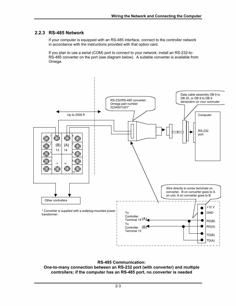
2.2.3 RS-485 Network
If your computer is equipped with an RS-485 interface, connect to the controller networkin accordance with the instructions provided with that option card.
If you plan to use a serial (COM) port to connect to your network, install an RS-232-to-RS-485 converter on the port (see diagram below). A suitable converter is available fromOmega.
* Converter is supplied with a wallplug-mounted powertransformer.
RS-485 Communication:One-to-many connection between an RS-232 port (with converter) and multiple
controllers; if the computer has an RS-485 port, no converter is needed
11
1
2
3
4
5
6
7
8
9
10
(B) (A)14
12
13
Wire directly to screw terminals onconverter. B on converter goes to Aon unit, A on converter goes to B
RD(B)
RD(A)
TD(B)
TD(A)
ToControllerTerminal 13
ToControllerTerminal 14 (A)
(B)
GND
+12 V
Up to 2000 ft
RS-232/RS-485 converter;Omega part number223A001U01*
Computer
RS-232port
Data cable assembly DB 9 toDB 25, or DB 9 to DB 9depending on your computer
Other controllers

CN8-SWÔ UserÕs Guide
2-4
3-1
3. Installing the Software and Logging In
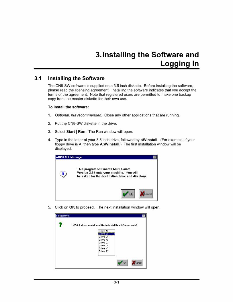
3.1 Installing the SoftwareThe CN8-SW software is supplied on a 3.5 inch diskette. Before installing the software,please read the licensing agreement. Installing the software indicates that you accept theterms of the agreement. Note that registered users are permitted to make one backupcopy from the master diskette for their own use.
To install the software:
1. Optional, but recommended: Close any other applications that are running.
2. Put the CN8-SW diskette in the drive.
3. Select Start | Run. The Run window will open.
4. Type in the letter of your 3.5 inch drive, followed by :\Winstall. (For example, if yourfloppy drive is A, then type A:\Winstall.) The first installation window will bedisplayed.
5. Click on OK to proceed. The next installation window will open.
CN8-SWÔ UserÕs Guide
3-2
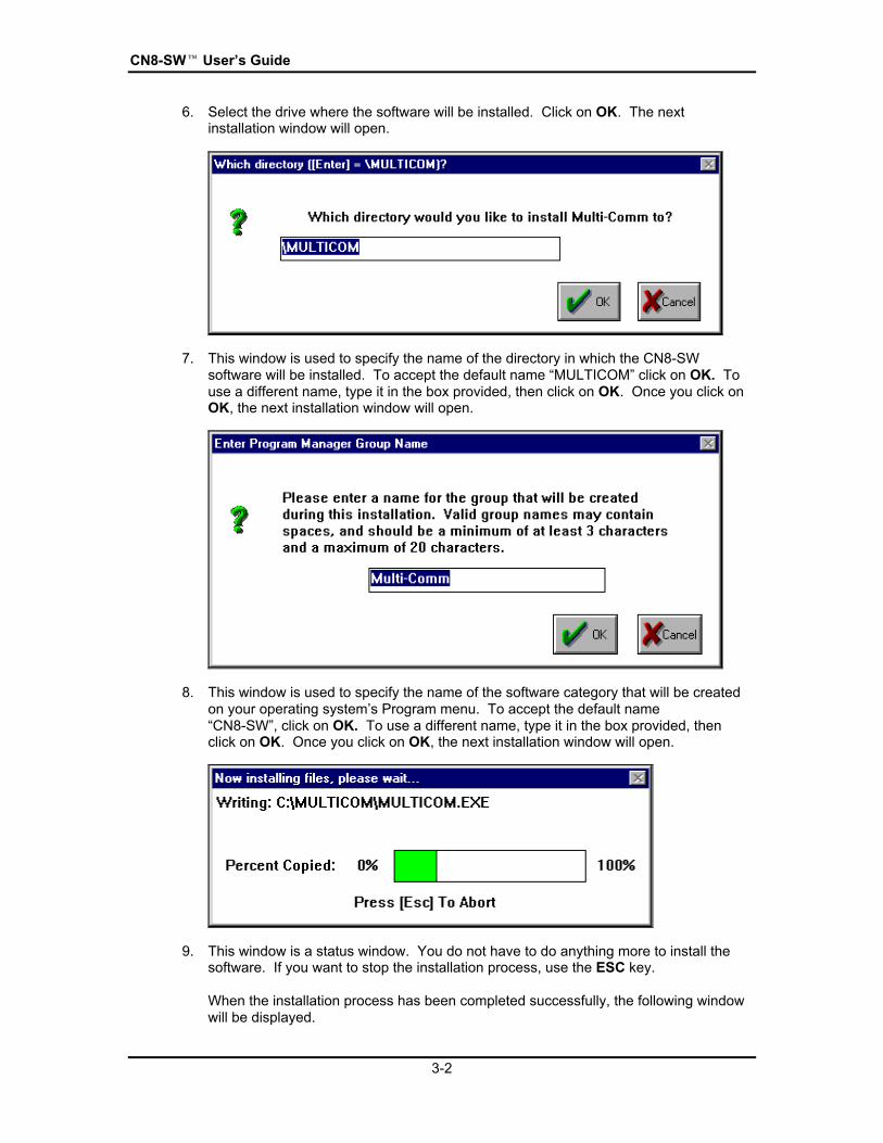
6. Select the drive where the software will be installed. Click on OK. The nextinstallation window will open.
7. This window is used to specify the name of the directory in which the CN8-SWsoftware will be installed. To accept the default name ÒMULTICOMÓ click on OK. Touse a different name, type it in the box provided, then click on OK. Once you click onOK, the next installation window will open.
8. This window is used to specify the name of the software category that will be createdon your operating systemÕs Program menu. To accept the default nameÒCN8-SWÓ, click on OK. To use a different name, type it in the box provided, thenclick on OK. Once you click on OK, the next installation window will open.
9. This window is a status window. You do not have to do anything more to install thesoftware. If you want to stop the installation process, use the ESC key.
When the installation process has been completed successfully, the following windowwill be displayed.

Installing the Software and Logging In
3-3
10. To close the window and exit the installation program, click on OK.
3.2 Starting the SoftwareStart the software as you would any other installed application.

CN8-SWÔ UserÕs Guide
3-4
3.3 Logging In to CN8-SW Using the Default AccountWhen you start the CN8-SW application, the Operator Login Window will be displayed.
By default, newly installed CN8-SW software will be set up to recognize one loginaccount. This is user ÒMULTIÓ. The password is ÒCOMMÓ.
To log in:
1. Start the CN8-SW application.
2. Select File | Login. The Operator Login window will be displayed.
3. Click on the User Id text entry box and type in MULTI. CN8-SW user names andpasswords are case-sensitive. This means that capitalization matters. To thesoftware ÒMULTIÓ, ÒmultiÓ, and ÒMultiÓ are all different names.
4. Tab to the Password entry box or click on it. Type in COMM.
5. Click on OK. The CN8-SW window will open. Because the software was newlyinstalled, the main display will be blank. In the future, once communication has beenestablished with controllers, and the controller identities saved as a CN8-SW systemfile, logging in will result in the display of the controllers in the most recently used.MCS file.
Installing the Software and Logging In
3-5
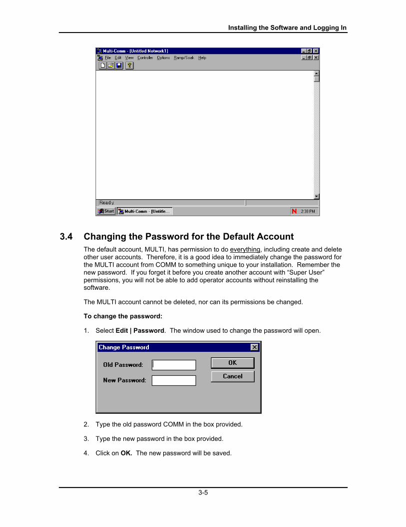
3.4 Changing the Password for the Default AccountThe default account, MULTI, has permission to do everything, including create and deleteother user accounts. Therefore, it is a good idea to immediately change the password forthe MULTI account from COMM to something unique to your installation. Remember thenew password. If you forget it before you create another account with ÒSuper UserÓpermissions, you will not be able to add operator accounts without reinstalling thesoftware.
The MULTI account cannot be deleted, nor can its permissions be changed.
To change the password:
1. Select Edit | Password. The window used to change the password will open.
2. Type the old password COMM in the box provided.
3. Type the new password in the box provided.
4. Click on OK. The new password will be saved.
CN8-SWÔ UserÕs Guide
3-6
3.5 Setting Up Operator AccountsAt most sites, operators will not need permission to use all CN8-SW functions,particularly the ability to create and delete other usersÕ accounts. Therefore, it is a goodidea for the CN8-SW system administrator (the person who knows the password to theMULTI account) to create login accounts for operators.
3.5.1 Permissions Available
The CN8-SW system supports several permission classes. To see these classes, take alook at the definition of the MULTI account.
To see the permissions available to a user account:
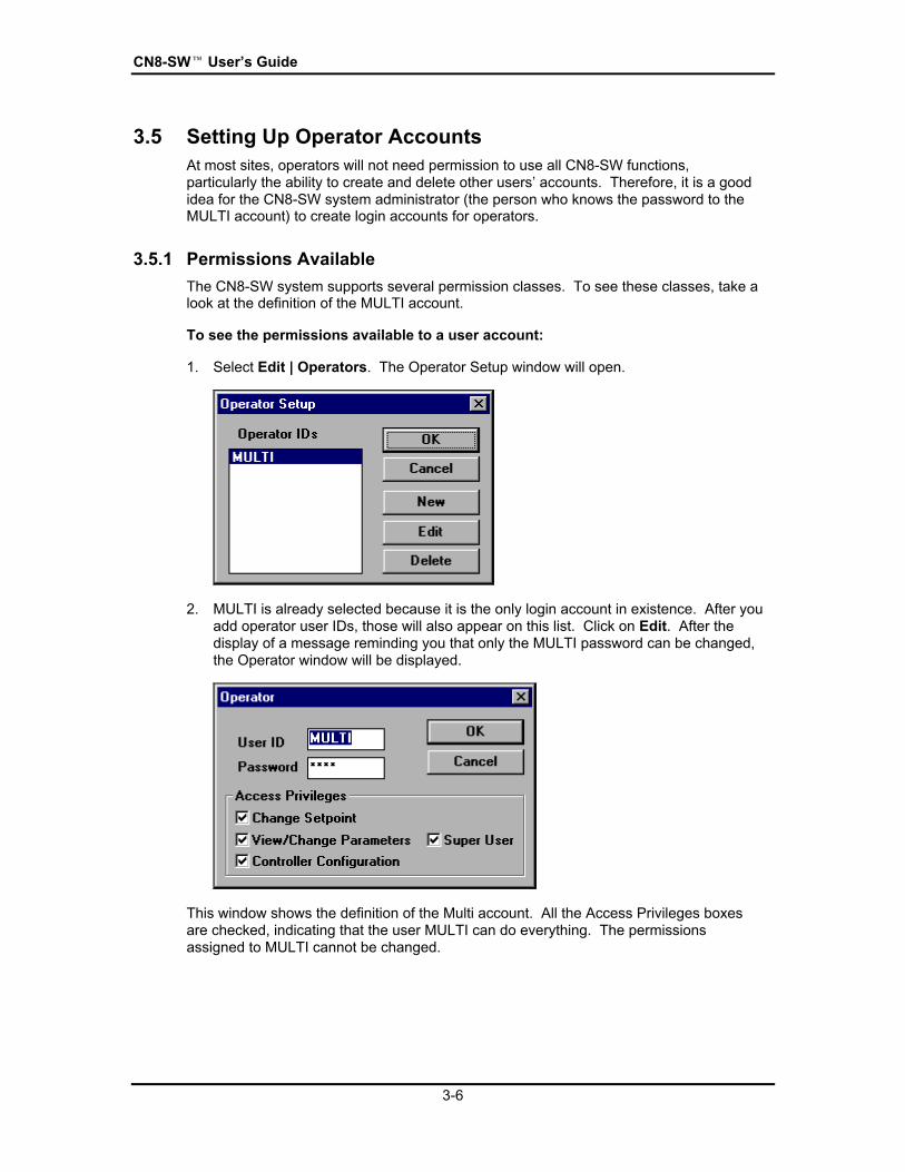
1. Select Edit | Operators. The Operator Setup window will open.
2. MULTI is already selected because it is the only login account in existence. After youadd operator user IDs, those will also appear on this list. Click on Edit. After thedisplay of a message reminding you that only the MULTI password can be changed,the Operator window will be displayed.
This window shows the definition of the Multi account. All the Access Privileges boxesare checked, indicating that the user MULTI can do everything. The permissionsassigned to MULTI cannot be changed.

Installing the Software and Logging In
3-7
The access privilege categories grant the following permissions.
Change Setpoint Change the setpoint using the Change Setpointwindow (see Section 6), change the controller mode(see Section 7), and run ramp/soak recipes under thedirection of CN8-SW or under the direction of thecontroller (see Section 9).
View/Change Parameters Use the CN8-SW parameter window to view andchange the parameters stored in the controllersÕ non-volatile memory (see Section 8).
Controller Configuration Add and delete controllers from the CN8-SW system(see Section 4).
Super User Add and delete user accounts (operator login IDs)(see 3.5.2).
3.5.2 Procedure
To add an operator login account:
1. While logged in as MULTI, select Edit | Operators. The Operator Setup window willopen.
2. Click on New. The Operator window used to define a new login account will bedisplayed.
3. Enter the new User ID (0 to 10 letters and/or numbers).
4. Enter a password (optional, but recommended).

CN8-SWÔ UserÕs Guide
3-8
5. Click on the check box for each set of access privileges you want the user to have.ÒSuper UserÓ does not automatically include all the other privileges.
6. If you change your mind and want to clear a checked box, click on it again to ÒeraseÓthe check.
7. When you are satisfied with the user definition, click on OK . The window will beclosed and the user definition will be saved in a .DAT file in the directory where theCN8-SW software was installed.
3.6 Editing an Operator AccountTo edit an operator login account, use the procedure in 3.5.1 to select the operator,then change the password, and view and change privileges. You must be logged in asMULTI or another user with Super User privileges.
3.7 Deleting an Operator AccountTo delete an operator login account, use Edit | Operators to access the OperatorSetup window, select the operator, then click on Delete. You must be logged in asMULTI or another user with Super User privileges.
3.8 Logging Out of the CN8-SW ApplicationTo log out but leave the CN8-SW application open, use File | Logout.
To log out and close the CN8-SW application, use File | Exit.
4-1
4. Establishing Communication withControllers
4.1 IntroductionOnce you have connected the controllers and the computer to the network, installed theCN8-SW software, and changed the password on the MULTI login account, you areready to establish communication between the CN8-SW computer and the controllers onthe network.
You must do the following tasks.
· U s e t h e f r o n t p a n e l u s e r i n t e r f a c e o f e a c h c o n t r o l l e r t o a s s i g n e a c h a u n i q u e a d d r e s s ( b e t w e e n 1 a n d 2 5 4 ) .
· I f t h e O m e g a P l u s c o n t r o l l e r s Õ c o m m u n i c a t i o n p a r a m e t e r s h a v e b e e n c h a n g e d f r o m t h e f a c t o r y d e f a u l t s , u s e t h e f r o n t p a n e l o f e a c h c o n t r o l l e r t o s e t t h e c o m m u n i c a t i o n p a r a m e t e r s a t t h e i r d e f a u l t v a l u e s a s d e s c r i b e d i n 4 . 2 .
· U s e t h e C o m m u n i c a t i o n s o p t i o n o n t h e C N 8 - S W O p t i o n s m e n u t o s p e c i f y t h e C O M p o r t t o b e u s e d b y t h e M u l t i - C o m s o f t w a r e . If y o u c h o o s e n o t t o u s e t h e a u t o m a t i c Ò f i n d c o n t r o l l e r s Ó f e a t u r e d e s c r i b e d i n 4 . 4 . 2 t o s e t u p y o u r n e t w o r k , t h e n y o u m u s t a l s o s p e c i f y t h e b a u d r a t e t o b e u s e d b y t h e C N 8 - S W s o f t w a r e . 7 C o n f i g u r a t i o n o f c o m m u n i c a t i o n p a r a m e t e r s i s d e s c r i b e d i n 4 . 3 .
· S e t t h e c o m m u n i c a t i o n p a r a m e t e r s o f t h e c o n t r o l l e r s t h a t s u p p o r t t h e o r i g i n a l O m e g a p r o t o c o l t o m a t c h t h e C N 8 - S W s o f t w a r e a s d e s c r i b e d i n 4 . 2 .
· M a k e t h e C N 8 - S W s y s t e m a w a r e o f a l l d e v i c e s o n t h e n e t w o r k a s d e s c r i b e d i n 4 . 4 . T h i s c a n b e d o n e u s i n g t h e a u t o m a t i c Ò f i n d c o n t r o l l e r s Ó o p e r a t i o n , i n w h i c h t h e C N 8 - S W s y s t e m s e e k s a n d f i n d s O m e g a P l u s c o n t r o l l e r s u s i n g t h e d e f a u l t b a u d r a t e o f e a c h c o n t r o l l e r a n d s e t s a l l t h e O m e g a P l u s c o n t r o l l e r s t o w o r k a t 9 6 0 0 b a u d . Al t e r n a t i v e l y , y o u c a n a d d c o n t r o l l e r s t o t h e n e t w o r k o n e a t a t i m e . If y o u u s e t h i s m a n u a l m e t h o d , t h e n t h e s o f t w a r e w i l l p o l l a t t h e b a u d r a t e s p e c i f i e d i n t h e C N 8 - S W C o m m u n i c a t i o n s S e t u p w i n d o w .
· S a v e t h e s e t u p a s a n . M C S f i l e s a s d e s c r i b e d i n 4 . 8 .
7 If you do use the Òfind controllersÓ function, the CN8-SW software will automatically use 9600 baud.

CN8-SWÔ UserÕs Guide
4-2
4.2 Configuring Communication Parameters and AssigningNetwork Addresses in Controllers
4.2.1 Communication Parameters
Your goal is to make sure that:
· a l l t h e c o n t r o l l e r s t h a t s u p p o r t O m e g a P l u s p r o t o c o l h a v e t h e i r c o m m u n i c a t i o n p a r a m e t e r v a l u e s s e t t o t h e i r d e f a u l t s
· a l l t h e c o n t r o l l e r s t h a t s u p p o r t t h e o r i g i n a l O m e g a p r o t o c o l h a v e t h e i r b a u d r a t e s e t t o m a t c h t h e C N 8 - S W s o f t w a r e , a n d t h e i r o t h e r p a r a m e t e r s s e t t o 8 d a t a b i t s , n o p a r i t y , 1 s t o p b i t .
The CN8-SW software is designed to recognize Omega Plus controllers using thecontrollersÕ default communication parameters. Therefore, if any Omega Plus controllerÕscommunication parameters have been changed from the factory defaults, return thecommunication parameter values to their defaults. The default baud rate depends on thecontroller series, but all use 8 data bits, no parity, 1 stop bit.
· The network baud rate will be 9600 if you do use the automatic Òfind controllersÓfunction. The software will change each Omega Plus controllerÕs baud rate to9600.
· The network baud rate will be determined by the rate you configure for the CN8-SW software if you do not use the automatic Òfind controllerÕs functionÓ.
The baud rate of controllers that support the original Omega protocol can be read, but notchanged, by the CN8-SW computer. Therefore, you must use the front panel display andbuttons to set the baud rate in these controllers to 9600 (and make sure the othercommunication parameters are set to 8 data bits, no parity, 1 stop bit) before you use theautomatic recognition process described in 4.4.
· T h e c o m m u n i c a t i o n p a r a m e t e r s i n n e w ( Ò o u t - o f - t h e b o x Ó ) O m e g a P l u s c o n t r o l l e r s w e r e s e t t o t h e i r d e f a u l t s a t t h e f a c t o r y . If t h e c o n t r o l l e r s a r e n e w , y o u c a n p r o c e e d t o c o n f i g u r i n g n e t w o r k a d d r e s s e s ( s e e 4 . 2 . 2 ) .
· I f n e c e s s a r y , f o l l o w t h e i n s t r u c t i o n s p r o v i d e d i n t h e c o n t r o l l e r m a n u a l s t o p o w e r u p t h e c o n t r o l l e r s , a n d u s e t h e f r o n t p a n e l d i s p l a y a n d b u t t o n s t o s e t a l l t h e O m e g a P l u s P r o t o c o l c o n t r o l l e r s t o t h e i r d e f a u l t c o m m u n i c a t i o n p a r a m e t e r v a l u e s ( a n d a l l O m e g a P r o t o c o l c o n t r o l l e r s t o 9 6 0 0 , 8 d a t a b i t s , n o p a r i t y , 1 s t o p b i t ) , t h e n g o o n t o 4 . 2 . 2 .
Establishing Communication with Controllers
4-3
4.2.2 Network Addresses
Your goal is to assign each controller on the network a unique address between 1 and254.
This can be accomplished using the buttons and display on the front panel of thecontroller as described in the manual supplied with each controller.
If you will have fewer than 254 controllers on the network and plan to use the CN8-SWfunction of automatically detecting devices on the network, use the lowest addressnumbers first. The software will begin polling with address 1 and proceed up to 254unless you stop the polling process. You can save time getting your network up andrunning if you stop the process once you know the CN8-SW system has found thecontroller with the highest address number you have assigned.
Assign the addresses and go on to 4.3.

CN8-SWÔ UserÕs Guide
4-4
4.3 Configuring Communication Parameters for CN8-SWSystem
Your goal is to select the COM port to be used by the CN8-SW software.
· If you do not plan to use the automatic Òfind controllersÓ option described in 4.4,then you can also specify a baud rate other than 9600 (the default) for thenetwork.
· If you do use the automatic Òfind controllersÓ feature, then the software will use9600 baud, regardless of the baud rate specified using the CommunicationsSetup window shown below.
The other communication parameters must match the controller settings. All use 8 databits, no parity, 1 stop bit, which are also the CN8-SW defaults.
To configure the CN8-SW communication settings:
1. Launch the CN8-SW application as described in Section 3 and log in as MULTI.
2. Select Options | Communication. The Communications Setup window will open.
3. Use the Connector dropdown list to pick the port to be used. Sometimes, particularlywhen using a laptop computer, a COM port may already be in use without your beingaware of it. If you get a message ÒCOM 1 (or 2) in useÓ when you attempt to use theCN8-SW computer to poll controllers over the network as described later in thissection, use a different COM port.
4. If you do not plan to use the automatic Òfind controllersÓ option, use the Baud Ratedropdown list to set the baud rate at which you want the network to operate, usually9600.
5. If the CN8-SW communication settings were changed from the defaults, use the DataFormat dropdown list to set n,8,1.
6. If necessary, change the Polling Frequency from the default value. The PollingFrequency is the minimum number of milliseconds in the interval between the CN8-SW system receiving a reply from one controller and the system trying tocommunicate with the next controller.

Establishing Communication with Controllers
4-5
7. If necessary, change the Timeout from the default value. The Timeout is the numberof milliseconds the CN8-SW system will wait to receive a reply from a controllerbefore giving up and moving on to the next controller.
8. When the settings are correct, click on OK to save the settings and close the window.
CN8-SWÔ UserÕs Guide
4-6
4.4 Recognizing Controllers with the CN8-SW Software
4.4.1 Introduction
Once you have assigned a unique network address to each controller, and setcommunication parameters in all controllers to their defaults, and set the CN8-SW to usethe desired COM port, you are ready to enable the CN8-SW software to recognize thecontrollers.
· I f y o u i n t e n d f o r a l l o p e r a t o r s t o s e e a l l c o n t r o l l e r s , y o u c a n t a k e a d v a n t a g e o f t h e C N 8 - S W f u n c t i o n t h a t f i n d s a l l t h e p o w e r e d u p c o n t r o l l e r s o n t h e n e t w o r k b y p o l l i n g e v e r y a d d r e s s b e t w e e n 1 a n d 2 5 4 , a s d e s c r i b e d i n 4 . 4 . 2 . I f y o u u s e t h i s f e a t u r e , t h e n e t w o r k w i l l b e s e t t o o p e r a t e a t 9 6 0 0 b a u d , r e g a r d l e s s o f t h e b a u d r a t e s p e c i f i e d u s i n g C o m m u n i c a t i o n s S e t u p w i n d o w d e s c r i b e d i n 4 . 3 .
· I f y o u w a n t s o m e o p e r a t o r s t o b e a b l e t o s e e o n l y s o m e o f t h e c o n t r o l l e r s , y o u m u s t u s e t h e m a n u a l p r o c e s s d e s c r i b e d i n 4 . 4 . 3 . T h e s y s t e m w i l l u s e t h e b a u d r a t e s p e c i f i e d u s i n g C o m m u n i c a t i o n s S e t u p w i n d o w d e s c r i b e d i n 4 . 3 .
4.4.2 Automatically Using the Find Controllers Option
The CN8-SW Òfind controllersÓ option polls each address, beginning at 1 and continuinguntil it has polled address 254, unless you stop the process using the Options menu.During the Òfind controllersÓ process, the CN8-SW software first polls every address at9600 baud, the default rate used by some Omega Plus-compliant controllers. If the CN8-SW software is able to communicate with a controller at 9600 baud, the system adds thecontroller to the display. The CN8-SW system then polls the next address at the 9600rate.
After the CN8-SW system has polled every address (1 to 254) at 9600 baud, the softwaretemporarily switches itself to poll at 2400 baud, the other rate used by some Omega Pluscontrollers as the default. The CN8-SW software goes back to the lowest address atwhich it did not find a controller when polling at 9600 baud, and polls the address at 2400baud. If the CN8-SW system can communicate with a controller at that address using2400 baud, the CN8-SW system adds the controller to the display. The CN8-SWsoftware also changes the baud rate of the Omega Plus controller to 9600.
After the system has changed the baud rate of the controller it found using 2400 baud (orif the system does not find a controller at the address), the CN8-SW system then uses2400 to poll the next higher address at which it did not find a controller when polling at9600, and the process continues.
At the conclusion of the polling process (or if you stop the Òfind controllersÓ operation asdescribed in Step 6 below), the CN8-SW software switches itself back to 9600 baud.
· T h e C N 8 - S W s y s t e m p o l l s a d d r e s s 1 a t 9 6 0 0 b a u d , e s t a b l i s h e s c o m m u n i c a t i o n w i t h t h e 1 6 C c o n t r o l l e r , a d d s t h e c o n t r o l l e r t o t h e m a i n d i s p l a y , a n d m o v e s o n .
· T h e C N 8 - S W s y s t e m p o l l s a d d r e s s 2 a t 9 6 0 0 b a u d , e s t a b l i s h e s c o m m u n i c a t i o n w i t h t h e 1 6 C c o n t r o l l e r , a d d s i t t o t h e m a i n d i s p l a y , a n d m o v e s o n .
Establishing Communication with Controllers
4-7
· T h e s o f t w a r e p o l l s a d d r e s s e s 3 t h r o u g h 2 5 4 a t 9 6 0 0 b a u d .
· T h e n e t w o r k i s r e a d y t o o p e r a t e a t 9 6 0 0 b a u d .
To use the automatic function:
1. Make sure all the controllers are powered up.
2. Use the front panel display and buttons on controllers that do not support the OmegaPlus protocol to set their communication parameters to 9600 baud, 8 data bits, noparity, 1 stop bit. (The baud rate of controllers that support the original Omegaprotocol can be read, but not changed, by the CN8-SW computer.)
3. While you are logged in as MULTI (or another user with Controller ConfigurationPrivileges) select Options | Start Find Controllers. The process will begin.
4. You will be able to monitor the progress of the operation. A message in the statusbar (lower right corner of the main CN8-SW window), will be displayed: ÒChecking fora controller at IDnÓ. 8
5. As each controller is found, an image of its display will appear in the main CN8-SWwindow. By default the name of the controller will be the same as its addressnumber. You can give each controller a different name later (see 4.6).
6. When you see that the controller with the highest address number you assigned hasbeen recognized (appears on the main display), you can stop the process usingOptions |Stop Find Controllers.
7. After the find controller function has been completed or has been stopped asdescribed in Step 6, the CN8-SW software will begin normal operation at 9600 baud,polling the controllers and displaying their PV and SP values.
8 If the CN8-SW status bar is not visible, use the View menuÕs Status Bar item to display the status bar.
CN8-SWÔ UserÕs Guide
4-8
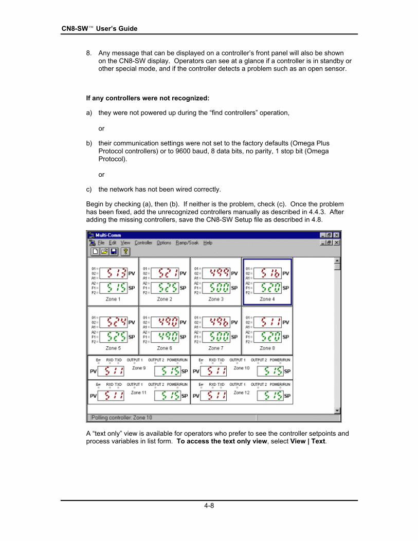
8. Any message that can be displayed on a controllerÕs front panel will also be shownon the CN8-SW display. Operators can see at a glance if a controller is in standby orother special mode, and if the controller detects a problem such as an open sensor.
If any controllers were not recognized:
a) they were not powered up during the Òfind controllersÓ operation,
or
b) their communication settings were not set to the factory defaults (Omega PlusProtocol controllers) or to 9600 baud, 8 data bits, no parity, 1 stop bit (OmegaProtocol).
or
c) the network has not been wired correctly.
Begin by checking (a), then (b). If neither is the problem, check (c). Once the problemhas been fixed, add the unrecognized controllers manually as described in 4.4.3. Afteradding the missing controllers, save the CN8-SW Setup file as described in 4.8.
A Òtext onlyÓ view is available for operators who prefer to see the controller setpoints andprocess variables in list form. To access the text only view, select View | Text.

Establishing Communication with Controllers
4-9
To return to the graphic view, select View | Graphic. When the instructions in thismanual refer to the Òmain CN8-SW windowÓ, that means the graphic view.

CN8-SWÔ UserÕs Guide
4-10
4.4.3 Manually Using the Controller Menu
If you want some operators to be able to see only some of the controllers on the network,you must use the manual process described here to add the controllers one operator willsee, save the configuration to an .MCS file as described in 4.8, then start again, addingcontrollers to create a new different .MCS file for the use of a second operator.
This manual process can also be used to establish communications between the CN8-SW computer and a controller that was added to the network after the automatic processin 4.4.2 was used.
To add a controller manually:
1. Make sure the controller is powered up.
2. Use the front panel display and buttons to set the controllerÕs communicationparameters to match the CN8-SW communication parameters.
3. While you are logged in as MULTI (or another user with Controller ConfigurationPrivileges) select Controller | Add. The Add Controller window will be displayed.
4. Type in the network ID assigned to the controller. This must match the ID stored inthe controller.
5. Type in an optional name to be associated with this controller on CN8-SW displays.If no name is entered, the system will use the controllerÕs address as its name.
6. Click on OK. The CN8-SW computer will poll for a controller at that address (usingthe baud rate specified in the Communications Setup window described in 4.2) andthe Add Controller window will close.
If a controller is found at that address, it will appear in the main CN8-SW window.
If no controller is found at that address or a controller has already been recognizedby the CN8-SW software at that address, a message will be displayed.
Repeat the process for other controllers as needed.

Establishing Communication with Controllers
4-11
4.5 Deleting a ControllerAny controller can be deleted from the CN8-SW setup, regardless of whether thecontroller was added using the automatic process described in 4.4.1 or the manualmethod described in 4.4.2.
To delete a controller:
1. While you are logged in as MULTI (or another user with Controller ConfigurationPrivileges) select the controller to be deleted by clicking on it (left button) on thegraphic display. The border of the controller will be highlighted.
2. Select Controller | Delete. The controller will be deleted without any confirmationmessage. However, if you have already saved the setup to an .MCS file asdescribed in 4.8, the controller will not be removed from the file until you save again.
If you change your mind about deleting the controller, add it again using the manualmethod in 4.4.2. Alternatively, close the .MCS file without saving so that the file isnot changed to reflect the deletion, then reopen the file. The controller will still bepart of the setup, because you did not save the file after you deleted the controller.

CN8-SWÔ UserÕs Guide
4-12
4.6 Changing Baud Rate after Communication Has BeenEstablished
You can use the CN8-SW application to change the rate of all controllers that support theOmega Plus Protocol. As soon as you change the rate, you will lose communication withthe controllers. Once all the controllers have been set to the same new rate, change theCN8-SW communication setting to match. Detailed instructions for changing the baudrate follow.
To change the baud rate after communication has been established:
1. While logged in as MULTI (or another user with View/Change Parameter privileges),select the controller by clicking on it in the main graphic display.
2. To see the present values of the configuration parameters stored in its non-volatilememory, select Controller | Parameters. The parameter window for that controllerwill open. By default, the Input ÒtabÓ will be on top.
3. Click on the Comm tab. The communication parameter values, including baud rate,will be displayed.

Establishing Communication with Controllers
4-13
4. To select another baud rate, use the dropdown list.
5. Click on OK. The value will be sent to the controller and the window will close.(Once the value is written to the controllerÕs non-volatile memory, communication withthis controller is lost until the CN8-SW baud rate has been set to match.)
6. Repeat the process to assign the same new baud rate to every Omega Pluscontroller.
7. Use the controller front panel display and buttons to set the same new baud rate inevery controller that supports the original Omega Protocol. (You can view, but notchange, the baud rate in these controllers using the CN8-SW parameters window.)
8. After you have set all the controllers to the same new rate, select Options |Communications.
9. Set the CN8-SW computer to match the new rate configured for all the controllers.
10. Communication with all controllers will be established again. The main display will beupdated to reflect the current process variable and setpoint for each controller.

CN8-SWÔ UserÕs Guide
4-14
4.7 Naming ControllersBy default, the CN8-SW displays use a controllerÕs address as its name. However, youcan assign a more meaningful name to each device. This can be done during themanual addition process described in 4.4.3. You can also assign a name (or change theassigned name) of any controller using the Controller | Configure menu function. Aname may contain up to twenty letters, numbers, spaces, and special characters.
The Controller Configuration window can also be used to change the network ID of acontroller. If you do change the address in the controllerÕs memory using the CN8-SWsystem, the system will not be able to communicate with the controller again until you usethe procedure described in 4.4.3 to add the controller to the system using the deviceÕsnew ID.
4.8 Saving the .MCS FileIt is very important that you save your CN8-SW setup in a CN8-SW Setup (.MCS) file.The contents of the .MCS file determine what controllers appear on the main display.The ability to create, save, and open a variety of .MCS files enables you to createdisplays that do not include all the controllers on the network hosted by the PC. Forexample, if Operator A is only interested in Controllers 1, 2, and 9, you can create an.MCS file that would cause the CN8-SW display to show only those controllers whenOperator A uses that file. Operator B could use a different .MCS file to see a differentcustom display, one containing only Controllers 3, 4, 6, and 9, for example.
If you do not save your setup to an .MCS file, then the next time you start the CN8-SWapplication you will have to repeat the recognition process. (If you try to close the CN8-SW software using File | Exit or double-clicking on the X at the top right of the main CN8-SW window, you will be prompted to save.)
To save the setup to the .MCS file now open (named at the top of the main CN8-SW
window), use File | Save (or the button on the toolbar). The configuration will besaved to the open file.
To save the setup to an .MCS file with a new name, use File | Save As. Theoperating system Save As window will open. Use it to specify the destination directoryand file name for the .MCS file.
4.9 Closing an .MCS FileTo close an .MCS file, use File | Close. Before the file is closed you will be prompted tosave it if you have added any controllers or changed any controller names since the filewas last saved.
4.10 Creating a New .MCS File
To create a new .MCS file, use File | New (or the button on the toolbar). The open.MCS file will be closed and the main display cleared. You can now add controllers for anew CN8-SW setup.

Establishing Communication with Controllers
4-15
4.11 Opening an Existing .MCS File
To open a different .MCS file, use File | Open (or button on the toolbar). Theoperating system Open window will be displayed. Use it to select the .MCS file to open.

CN8-SWÔ UserÕs Guide
4-16

5-1
5. Configuring Local Alarms
5.1 IntroductionThe CN8-SW system can use the Omega Plus Protocol to read the alarm state of anycontroller that supports the protocol. Therefore, if an Omega Plus controllerÕs alarmparameters have been configured and the controller has detected an alarm condition, theA1 or A2 indicator on the controllerÕs Òfront panelÓ on the CN8-SW main display willappear to be lit (red), matching the behavior of the A1 and A2 indicators on the controllerfaceplate. The process value on the CN8-SW graphic display will also change color frommagenta (normal) to red (alarm). Controller alarm parameter values can be changedusing the CN8-SW software using the procedure described in Section 7.
As a bonus, the CN8-SW supports Òlocal alarmsÓ. These two process alarms can beconfigured in CN8-SW for each controller on the network, including controllers that do notprovide an alarm function of their own, and controllers that support the original OmegaProtocol.9 If a controllerÕs PV exceeds (high alarm) or falls below (low alarm) theconfigured local alarm limit, the alarm indicators on the main display will ÒlightÓ and thePV will change to red. Local alarms are configured using the procedure describedbelow.
5.2 ProcedureTo configure local process alarms:
1. While logged in as MULTI (or another user with Controller Configuration privileges),select Controller | Alarms. The Local Alarms window will open.
2. To enable local process alarm 1 (signaled using the controller imageÕs A1 indicatoron the main display), click on the box to the left of Process High.
9 Although some controllers that support the original Omega Protocol do provide parameters forconfiguration of controller alarms (such as the Series 16 controlers), their alarm status cannot be readusing the original Omega protocol.

CN8-SWÔ UserÕs Guide
5-2
3. To enable local process alarm 2 (signaled using the A2 indicator on the CN8-SWdisplay), click on the box to the left of Process Low.
4. Type in the alarm limit for each alarm.
5. Click on OK to save the changes and close the window.
6-1
6. Viewing Process Values and Changing Setpoint
6.1 IntroductionFor your convenience, the CN8-SW system provides several ways to view processvariable and setpoint as described in 6.2 and 6.3.
Any operator whose login account is configured with the appropriate privilege can use theCN8-SW system to change a controllerÕs setpoint as described in 6.4. (Instructions forchanging the setpoint using ramp and soak recipes are in Section 9.)
Some Omega controllers can use the single step Ramp to Setpoint function at timesother than at startup. The CN8-SW system provides a method to start the timer on theramp to setpoint as described in 6.5.

CN8-SWÔ UserÕs Guide
6-2
6.2 Viewing PV and SP in the Main WindowThe CN8-SW system always displays process value and setpoint for every controller inthe main window, either on the graphic view or the list view. The refresh rate isdependent on baud rate, the number of controllers on the network, and the configuredpolling frequency and timeout (see 4.3).

Viewing Process Values and Changing Setpoint
6-3
6.3 Viewing PV and SP in a GraphThe CN8-SW system allows operators to display a trend graph showing any controllerÕsSP and PV in real-time.
To view the real-time trend graph:
1. While logged in as MULTI (or another user with Controller Configuration privileges),select the controller by clicking on its image in the main graphic display. The borderof the controller will be highlighted.
2. Select Controller | Graph. The trend graph will be displayed.
Initially the graph will not show any trend tracings. However, as soon as the selectedcontroller is polled by the CN8-SW system, trend tracings will begin to be drawn. As longas the Graph Window remains open, the trend tracings will be updated.
To close the Graph Window, double-click on the X in the top right corner.

CN8-SWÔ UserÕs Guide
6-4
6.4 Changing the Setpoint Using the Setpoint Dialog BoxAny operator whose login account is configured with the appropriate privilege can use theCN8-SW system to change a controllerÕs setpoint.
To change a controllerÕs setpoint:
1. Access the window used to change the setpoint by:
· r i g h t - c l i c k i n g o n t h e c o n t r o l l e r Õ s i m a g e i n t h e m a i n d i s p l a y ,
o r
· l e f t - c l i c k i n g o n t h e c o n t r o l l e r t o s e l e c t i t , t h e n s e l e c t i n g C o n t r o l l e r | S e t p o i n t .
Either of these actions will open the Setpoint window.
2. Enter the new setpoint.
3. If you want the setpoint to be written to the controllerÕs non-volatile memory when youclick on Send, click on the box in front of ÒPermanentÓ. The box will be checked.(Clicking on the box again clears it.) If the controllerÕs power is cycled after you clickon Send, the new SP will be used again when power is restored, because the newSP will have been stored in the controllerÕs non-volatile memory.
or
If you want the setpoint to be written to temporary (volatile RAM) memory when youclick on Send, do not click on the ÒPermanentÓ box. If the controllerÕs power iscycled, the new SP will be lost.
4. Click on Send. The new setpoint will be sent to the controller the next time the CN8-SW computer communicates with the controller. 10
10 As with any RS-485 host, the CN8-SW computer communicates with one device at a time. To seewhich controller the CN8-SW application is currently communicating with, check the message at the leftof the status bar (at the bottom of the CN8-SW main window). If the status bar is not visible, use theView menuÕs Status Bar item to display the status bar.

Viewing Process Values and Changing Setpoint
6-5
6.5 Configuring and Invoking the Single-Step Ramp FunctionThe CN8-SW system provides a method to configure the single-step ramp time. Thesoftware also provides a means to invoke this single-step Ramp to Setpoint function inthose Omega controllers that can use the function at times other than at startup.
To configure the timer for the single step Ramp to Setpoint function:
1. While logged in as MULTI (or another user with View/Change Parameter privileges),select the controller by clicking on it in the main graphic display.
2. To see the present values of all parameters stored in the controllerÕs non-volatilememory, select Controller | Parameters. The parameter window for that controllerwill open. By default, the Input ÒtabÓ will be on top.
3. Click on the Recipe tab. The existing recipe-related parameter values will bedisplayed.
4. To enable Single-Step Ramp, click on the white dot (Òradio buttonÓ) next to it. A blackdot in the circle indicates that the function has been selected. The gray number inthe Ramp Time entry box will become black, indicating that the number can bechanged.
5. Enter the ramp time (in minutes) to be used to achieve the current setpoint wheneither of two conditions occur: power to the controller is cycled or the CN8-SWsystem is used to gradually ramp to the current setpoint.
6. Click on OK. The value will be sent to the controller and the window will close.

CN8-SWÔ UserÕs Guide
6-6
To invoke the single step ramp function:
1. Select the controller by clicking on its image in the main graphic display. The borderof the controller will be highlighted.
2. Select Controller | Start Recipe.11 The function will be invoked. (If the RecipeOption is set to ÒDisabledÓ, a confirmation message will be displayed before the PV isramped to the setpoint; the default one minute will be used.)
11 If the Recipe Option is set to ÒMulti-Step RampÓ, then the Controller menu Start Recipe function willbegin execution of the ramp and soak recipe stored in the controllerÕs recipe parameters as described inSection 8.

7-1
7. Changing Controller Modeand Using Autotune
7.1 IntroductionThe CN8-SW system provides operators with an easy, reliable way of changing acontrollerÕs mode without using the unitÕs front panel. This ability to change modeincludes placing the controller in Autotune. Before putting a controller in Autotune, besure to read the manual supplied with the controller. Autotune will not work correctlyunless you prepare the process and the controller as described in the controller manuals.
7.2 ProcedureTo change a controllerÕs mode:
1. While logged in as MULTI (or another operator with View/Change Parametersprivileges), select the controller by clicking on its image in the main graphic display.The border of the controller will be highlighted.
2. Select Controller | Standby (or Manual or Tune). (If you attempt to put thecontroller into Autotune mode, a confirmation message will be displayed. Beforeusing Autotune, you should read the manual supplied with the controller and complywith the Autotune guidelines provided in that manual. After you acknowledge theconfirmation message, the Autotune command will be sent to the controller.)
3. The image of the controller on the main display will match the controllerÕs display inthe new mode. For example, in Standby mode the PV value will alternate with themessage ÒStbYÓ as shown in the following picture (see the ÒZone 4Ó controller).

CN8-SWÔ UserÕs Guide
7-2
4. To take the controller out of the mode, select the controller again.
5. Open the Controller menu. You will see the controllerÕs current special modechecked. For example, if the controller is in Standby, then the menu will showÖ Standby. Click on the checked mode to take the controller out of that mode.

8-1
8. Viewing and Changing ControllerConfiguration Parameters
8.1 IntroductionThe CN8-SW system permits any operator with View/Change Parameter privileges toaccess parameter values stored in each controllerÕs memory.
The Omega Plus Protocol supports viewing and changing all parameter values over thenetwork. These Omega Plus controller values are read and stored in non-volatile(permanent) memory.
The original Omega Protocol supports viewing the most important parameters andchanging a sub-set of these parameters. You can specify whether you want to see andchange the values in volatile (temporary) memory or in non-volatile (permanent) memory.
8.2 Accessing Configuration Parameter DisplaysTo access the parameter displays:
1. Log in as MULTI (or another user with View/Change Parameter privileges).
2. Use one of the following two methods to access the displays:
· select the controller by clicking on it in the main graphic display, then usingController | Parameters,
or
· double-click on any controller in the main graphic display.
Either method will open the window showing the current value of the controllerÕsaccessible parameters.
In the case of an Omega Plus-compliant controller, the window will contain a set oftabbed ÒlayersÓ. Click on a tab to select the group of parameters to be viewed.
8.3 Using Configuration Parameter DisplaysBe aware that not all displayed parameters apply to the selected device, or to the currentconfiguration. In some cases the value of an unused parameter is gray, and no input isaccepted. For example, on the 16th DIN Omega CN8500 Input tab shown earlier in thissection, the Low Scale and High Scale parameters do not apply when a thermocoupleinput is used. Therefore, the Low Scale and High Scale values are gray. They do notapply to the current configuration and cannot be changed.

CN8-SWÔ UserÕs Guide
8-2
Sometimes it is possible to type a value in the CN8-SW window, but the value will not beaccepted by the controller. The value will not be accepted if the controller hardware doesnot support use of the parameter. You will be informed by a CN8-SW message that thecontroller will not accept the input.
The displayed values are currently stored in the controller. If you change a value in aparameter window, the change does not take effect until the next scan cycle after youclick on the Apply button.
Note that some controllers make a distinction between values stored in volatile(temporary) memory and those stored in non-volatile (permanent) memory. Theparameter displays for those devices are supplied with Temporary and Permanentselections. Use these to specify the destination of an entered value before applying it.
9-1
9. Configuring and RunningRamp and Soak Recipes
9.1 IntroductionUse the CN8-SW Ramp and Soak function to configure any number of recipes consistingof any number of ramp and soak steps. These recipes are stored on the CN8-SWcomputer. Under the direction of CN8-SW, any controller on the network can executeyour choice of recipe, even models that do not support configuration and execution oframp and soak cycles using the controller front panel. Instructions for configuring theserecipes are in 9.2. Instructions for running these recipes are in 9.3.
The CN8-SW displays also provide a quick way to configure and run recipes that use thecontrollerÕs own recipe parameters. Instructions for configuring these recipes are in 9.4.Instructions for running these recipes are in 9.5.

CN8-SWÔ UserÕs Guide
9-2
9.2 Configuring CN8-SW Recipes
9.2.1 Creating a New Recipe
To create a new recipe to be run on any controller under the direction of the CN8-SW system:
1. While logged on as MULTI (or another user with View/Change Parameter privileges),select Ramp/Soak | New. The Recipe Editor window will be displayed.
You will use the Ramp Time, Soak Level, and Soak Time boxes to configure eachstep, then use the Append Step button to add the step to the end of the recipe in thelarge white box. (Steps can also be inserted, edited, and deleted as describedbelow.)
2. Enter a recipe name. This name will be used on the list of recipes on the list of activerecipes and the list of ÒheldÓ recipes. (This will not be the name of the recipe fileunless you use the same name when you Save As.)
3. Select the engineering units to be used by clicking on the white dot in front of yourchoice. A black dot will indicate that an option has been selected.
4. Use the Termination State dropdown list to specify what you want to happen whenexecution of the recipe has been completed. (If you stop execution of a recipe beforecompletion, the setpoint will remain at the value it has when you stop execution.)
5. Use the Repeats box to enter the number of times you want the recipe to executeeach time it is run. If you want the recipe to run once, leave the Repeats value at thedefault, zero. If you want the recipe to cycle continuously once started, click on thebox to the left of ÒContinuousÓ. The box will be checked, indicating that the optionhas been selected.

Configuring and Running Ramp and Soak Recipes
9-3
6. Enter a Holdback value of at least 1, or disable holdback.12
7. Enter the Ramp Time, Soak Level (setpoint), and Soak Time for a recipe step in theboxes provided.13
8. Click on Append Step. The step will be added below the steps already in the recipebox. The Ramp Time, Soak Level, and Soak Time boxes will be cleared inpreparation for entering your next step.
9. Repeat Steps 7 and 8 as many times as you want.
10. Save the .RCP file for the first time using Save As. A window will open in which youcan specify the filename and directory. You must replace ÒUntitledÒ in the windowwith a meaningful file name ending with the .rcp extension. This will be the name youselect when you run the recipe.
12 If you are concerned that your process might not be responsive enough to reach the soak levels in thespecified ramp times, use the holdback feature. If holdback is enabled, then the system will not allow thesetpoint to become more than n engineering units away from the process value, where n is the Holdbackvalue. The system will Òhold backÓ the SP until the PV has had a chance to catch up. This has the effectof Òstopping the clockÓ on the SP ramp time until the PV is within n units of the SP.
The specified holdback value n will also be applied to the soak level. If the temperature falls more than nunits from the soak level, then the clock is stopped on the soak time until the PV is again within n units ofthe SP specified for the soak level.
13 Because of the effect of the holdback value, these ramp and soak times should be consideredminimums if holdback is enabled.

CN8-SWÔ UserÕs Guide
9-4
11. To delete a step from the recipe as shown in the white box, click on the step to selectit. The values of the selected step will be displayed in the Ramp Time, Soak Level,and Soak Time boxes. Click on Delete Step. The step will be removed from therecipe.
12. To edit a step, select it. Its values will be displayed in the Ramp Time, Soak Level,and Soak Time boxes. Make your changes, then click on Edit Step. The new valueswill replace those in the selected step.
13. To insert a step, select the step it should precede. The values of the selected stepwill be displayed in the Ramp Time, Soak Level, and Soak Time boxes. Enter thevalues for the step to be inserted, then click on Insert Step. The new step will beinserted before the step selected.
14. To save the recipe without closing the Recipe Editor window, click on Save. The filewill be saved to the file specified in Step 10, overwriting the old contents of the file.
15. When the recipe displayed in the white box meets with your approval, click on Saveand Close. The recipe will be saved to the .rcp file and the editor will close.
While you are learning to use the Recipe Editor, it is a good idea to use the Ramp/Soak |Edit function described in 9.2.2 to take a second look at your recipe before running it.
9.2.2 Editing an Existing Recipe
The same Recipe Editor functions are used to edit an existing recipe. Use Ramp/Soak |Edit to open the window used to select the .rcp file to be edited. Once you have selecteda file, the Recipe Editor will open. The steps in the existing file will be displayed in thewhite box. The previous selections for engineering units, holdback, etc. will be filled in.Add, delete, edit, and insert steps as needed, then use Save to overwrite the old recipefile you selected, or Save As to create a new file.

Configuring and Running Ramp and Soak Recipes
9-5
9.3 Running CN8-SW Recipes
9.3.1 Starting to Run a Recipe
To run a CN8-SW Ramp/Soak recipe:
1. While logged in as MULTI (or another user with View/Change Parameter privileges),select Ramp/Soak | Run. The Open Recipe window will open.
2. Select the .rcp file to be run and click on OK. The Run Recipe Controller Selectionwindow will open.
3. This window lists the name and network address of every control not currentlyexecuting a recipe under the direction of the CN8-SW system. Select one or morecontrollers. (You can hold down the Shift key to select multiple controllers that aretogether on the list, or hold down the Control key to select multiple controllers that arescattered on the list.)
4. Click on OK. The Run Recipe Controller Selection window will close, and the CN8-SW system will begin running the recipe on the selected controller(s). On the CN8-SW main display, the PV of any controller running the recipe will alternate with thedisplay of Òr-SÓ.
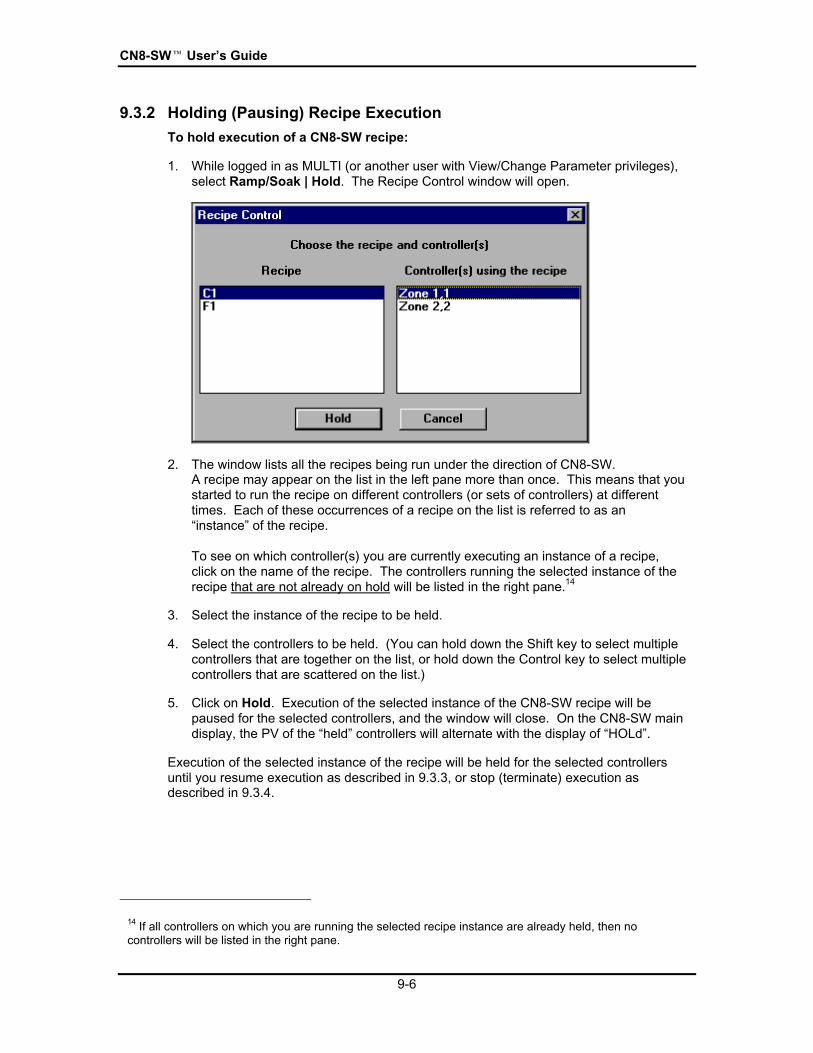
CN8-SWÔ UserÕs Guide
9-6
9.3.2 Holding (Pausing) Recipe Execution
To hold execution of a CN8-SW recipe:
1. While logged in as MULTI (or another user with View/Change Parameter privileges),select Ramp/Soak | Hold. The Recipe Control window will open.
2. The window lists all the recipes being run under the direction of CN8-SW.A recipe may appear on the list in the left pane more than once. This means that youstarted to run the recipe on different controllers (or sets of controllers) at differenttimes. Each of these occurrences of a recipe on the list is referred to as anÒinstanceÓ of the recipe.
To see on which controller(s) you are currently executing an instance of a recipe,click on the name of the recipe. The controllers running the selected instance of therecipe that are not already on hold will be listed in the right pane.14
3. Select the instance of the recipe to be held.
4. Select the controllers to be held. (You can hold down the Shift key to select multiplecontrollers that are together on the list, or hold down the Control key to select multiplecontrollers that are scattered on the list.)
5. Click on Hold. Execution of the selected instance of the CN8-SW recipe will bepaused for the selected controllers, and the window will close. On the CN8-SW maindisplay, the PV of the ÒheldÓ controllers will alternate with the display of ÒHOLdÓ.
Execution of the selected instance of the recipe will be held for the selected controllersuntil you resume execution as described in 9.3.3, or stop (terminate) execution asdescribed in 9.3.4.
14 If all controllers on which you are running the selected recipe instance are already held, then nocontrollers will be listed in the right pane.

Configuring and Running Ramp and Soak Recipes
9-7
9.3.3 Resuming Recipe Execution
To resume execution of a ÒheldÓ recipe:
1. While logged in as MULTI (or another user with View/Change Parameter privileges),select Ramp/Soak | Resume. The Recipe Control window will open.
2. The window lists all the recipes being run under the direction of CN8-SW.A recipe may appear on the list in the left pane more than once. This means that youstarted to run the recipe on different controllers (or sets of controllers) at differenttimes. Each of these occurrences of a recipe on the list is referred to as anÒinstanceÓ of the recipe.
To see on which controllers you have held an instance of a recipe, click on the nameof the recipe. The controllers on hold for the selected instance of the recipe will belisted in the right pane.15 Execution of the selected recipe instance may have beenheld on the controllers in this group at different times.
3. Select the instance of the recipe to be resumed.
4. Select one or more controllers to be resumed. (You can hold down the Shift key toselect multiple controllers that are together on the list, or hold down the Control key toselect multiple controllers that are scattered on the list.)
5. Click on Resume. Execution of the selected instance of the recipe will resume onthe selected controllers at the point in the recipe where it was held for each controller.Execution of the recipe can resume at different steps in the recipe in differentcontrollers. (Although you started to run the recipe instance in all the controllers atthe same time, you may have held execution at different times.) On the CN8-SWmain display, the PV of the selected controllers will again alternate with the display ofÒr-SÓ, indicating that a CN8-SW recipe is active using those controllers.
15 If the CN8-SW system is not holding execution of the recipe instance for any controllers, then nocontrollers will be listed in the right pane.

CN8-SWÔ UserÕs Guide
9-8
9.3.4 Stopping Recipe Execution
To stop execution of a CN8-SW recipe:
1. While logged in as MULTI (or another user with View/Change Parameter privileges),select Ramp/Soak | Stop. The Recipe Control window will open.
2. The window lists all the recipes being run under the direction of CN8-SW (both activeand held). A recipe may appear on the list in the left pane more than once. Thismeans that you started to run the recipe on different controllers (or sets of controllers)at different times. Each of these occurrences of a recipe on the list is referred to asan ÒinstanceÓ of the recipe.
To see on which controller(s) you are currently running an instance of a recipe, clickon the name of the recipe.
3. Select the instance of the recipe to be stopped.
4. Select one or more controllers. (You can hold down the Shift key to select multiplecontrollers that are together on the list, or hold down the Control key to select multiplecontrollers that are scattered on the list.)
5. Click on Stop. Running of the selected instance of the CN8-SW recipe using theselected controllers will end. The setpoint for each selected controller will remainwhere the setpoint was when the recipe was stopped, not at the value determined bythe Termination State configured for the recipe.
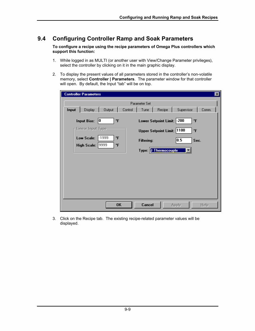
Configuring and Running Ramp and Soak Recipes
9-9
9.4 Configuring Controller Ramp and Soak ParametersTo configure a recipe using the recipe parameters of Omega Plus controllers whichsupport this function:
1. While logged in as MULTI (or another user with View/Change Parameter privileges),select the controller by clicking on it in the main graphic display.
2. To display the present values of all parameters stored in the controllerÕs non-volatilememory, select Controller | Parameters. The parameter window for that controllerwill open. By default, the Input ÒtabÓ will be on top.
3. Click on the Recipe tab. The existing recipe-related parameter values will bedisplayed.
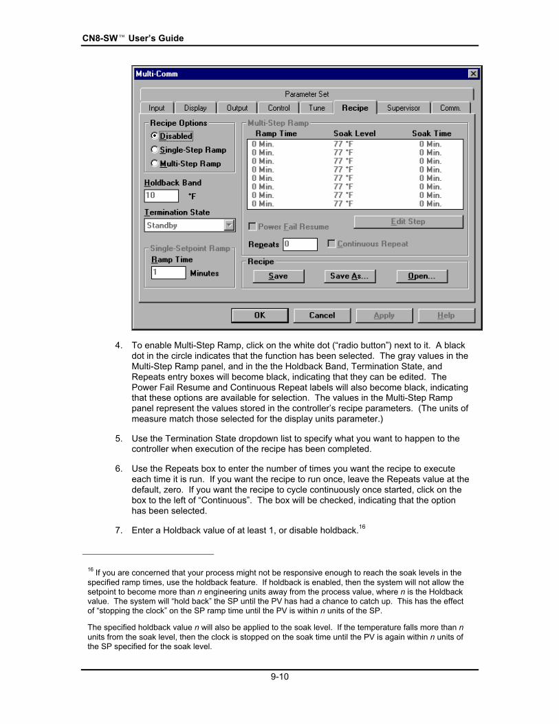
CN8-SWÔ UserÕs Guide
9-10
4. To enable Multi-Step Ramp, click on the white dot (Òradio buttonÓ) next to it. A blackdot in the circle indicates that the function has been selected. The gray values in theMulti-Step Ramp panel, and in the the Holdback Band, Termination State, andRepeats entry boxes will become black, indicating that they can be edited. ThePower Fail Resume and Continuous Repeat labels will also become black, indicatingthat these options are available for selection. The values in the Multi-Step Ramppanel represent the values stored in the controllerÕs recipe parameters. (The units ofmeasure match those selected for the display units parameter.)
5. Use the Termination State dropdown list to specify what you want to happen to thecontroller when execution of the recipe has been completed.
6. Use the Repeats box to enter the number of times you want the recipe to executeeach time it is run. If you want the recipe to run once, leave the Repeats value at thedefault, zero. If you want the recipe to cycle continuously once started, click on thebox to the left of ÒContinuousÓ. The box will be checked, indicating that the optionhas been selected.
7. Enter a Holdback value of at least 1, or disable holdback.16
16 If you are concerned that your process might not be responsive enough to reach the soak levels in thespecified ramp times, use the holdback feature. If holdback is enabled, then the system will not allow thesetpoint to become more than n engineering units away from the process value, where n is the Holdbackvalue. The system will Òhold backÓ the SP until the PV has had a chance to catch up. This has the effectof Òstopping the clockÓ on the SP ramp time until the PV is within n units of the SP.
The specified holdback value n will also be applied to the soak level. If the temperature falls more than nunits from the soak level, then the clock is stopped on the soak time until the PV is again within n units ofthe SP specified for the soak level.

Configuring and Running Ramp and Soak Recipes
9-11
8. To edit a step, click on it to select it, then click on Edit Step.
9. Enter the Ramp Time, Soak Level (setpoint), and Soak Time for a recipe step in theboxes provided.17
10. Repeat Steps 8 and 9 until the recipe meets the needs of your application.
11. If you want to save this recipe to an .RS file on a drive accessible to the CN8-SWcomputer, use the Save As button. A window will open in which you can specify thefilename and directory. You must replace ÒUntitledÒ in the wintdow with a meaningfulfile name ending with the .RS extension. (If you make further changes and want tosave to the same file, use the Save button.) When you click on OK, the ramp time,soak level, and soak time values will be saved in the file. They will not be sent to thecontroller.
12. When you are ready to write the recipe values to the controller, click on Apply, orOK. The values will be written to the controller during the next scan cycle. If you useApply, the parameters window will stay open. If you use OK, the window will close.
To open a previously saved controller recipe .RS file (not a CN8-SW .RCP recipe file),use the Open button on the Recipe parameter tab and select the file. The ramp time,soak level, and soak time values in the file will be displayed on the Recipe tab. Thevalues will not be sent to the controller until you click on Apply or OK.
17 Because of the effect of the holdback value, these ramp and soak times should be consideredminimums if holdback is enabled.

CN8-SWÔ UserÕs Guide
9-12
9.5 Running Controller Ramp and Soak CyclesTo run a multi-step ramp and soak recipe based on the values stored in thecontroller:
1. Select the controller by clicking on its image in the main graphic display. The borderof the controller will be highlighted.
2. Select Controller | Start Recipe. The function will be invoked. Note that if theRecipe Option is set to ÒSingle-Step RampÓ or ÒDisabledÓ, then the multi-step rampfunction is not available. In these cases, using Controller | Start Recipe will invokethe single-step ramp function. (If the Recipe Option is set to ÒDisabledÓ, the CN8-SWsoftware will display a confirmation message before executing a single-step rampbased on the one minute default ramp time.)
When a controller is executing a ramp/soak step based on values stored in thecontrollerÕs parameters, the PV will alternate with ÒrSÓ on the CN8-SW main display tomatch the controllerÕs front panel display.

10-1
10. Storing and Loading ControllerConfigurations
10.1 IntroductionAll the configuration parameter values stored in non-volatile memory in a controller thatsupports Omega Plus Protocol can be saved to the PC and loaded to the same ordifferent controllers. Backing up a unique controller configuration on a PC or removablemedium is always prudent. If a controller is damaged later and must be replaced, thecustom configuration can be loaded quickly to a spare controller, minimizing down time.
In large installations where many controllers use the same (or almost the same)configuration, its easy to configure one controller using the CN8-SW display, save theparameter set to the PC, then load the same parameter set to many other controllers onthe network. The time saved by eliminating the need to configure each controller at itsfront panel more than pays for the CN8-SW package. (If you load the same configurationinto more than one controller, remember to give each controller a unique networkaddress using the controllerÕs front panel.)
The ability to store and load a controller configuration also enables you to reuse tuningparameter values that have proved to be best for certain process conditions. If theresponsiveness of your process is altered at times, you may find it desirable to save setsof tuning parameters to be used under different circumstances.
For example, if you autotune the controller for optimum control of the temperature of anengraving cylinder while one size is in use, save the parameter set before installing alarger or smaller cylinder. The different size cylinder may heat at a different rate,requiring different tuning parameters to be used for optimum control. Save the newtuning as a parameter set with a different name. When the day comes that you have toreinstall the first cylinder, reload the parameter set, including the tuning parameters thatwere optimized for that cylinder.

CN8-SWÔ UserÕs Guide
10-2
10.2 Storing ConfigurationTo save an Omega Plus controllerÕs configuration on the CN8-SW computer:
1. While logged in as MULTI (or another user with View/Change Parameter privileges),select the controller by clicking on it in the main graphic display.
2. To display the present values of all parameters stored in the controllerÕs non-volatilememory, select Controller | Parameters. The parameter window for that controllerwill open. By default, the Input ÒtabÓ will be on top.
3. Click on the Parameter Set tab. It contains the buttons used to save and loadparameter sets.

Storing and Loading Controller Configurations
10-3
4. To save the parameter set in a .PRF file, click on Save As. The Save Parameter Setwindow will open. Use it to enter a filename (with a .PRF file extension) and tospecify a destination directory. (To save the parameter set to a file with the samename as the controller, click on Save. The file will be saved in the same directorywhere the CN8-SW software was installed.)
5. As the save progresses, a status window will be displayed. When the status windowcloses, the save operation is complete. You can click on OK to close the parameterwindow.

CN8-SWÔ UserÕs Guide
10-4
10.3 Loading ConfigurationTo save an Omega Plus controllerÕs configuration on the CN8-SW computer:
1. While logged in as MULTI (or another user with View/Change Parameter privileges),select the controller by clicking on it in the main graphic display.
2. To display the present values of all parameters stored in the controllerÕs non-volatilememory, select Controller | Parameters. The parameter window for that controllerwill open. By default, the Input ÒtabÓ will be on top.
3. Click on the Parameter Set tab. It contains the buttons used to save and loadparameter sets.

Storing and Loading Controller Configurations
10-5
4. To load a parameter set to the selected controller, click on Load. The OpenParameter Set window will open.
5. Select the name of the .PRF file to be loaded to the controller and click on OK. Theparameter values stored in the file will be written to the controller.
6. As the load progresses, status windows will be displayed. When no more statuswindows are displayed, the load has completed successfully. If the CN8-SW systemcould not write all the parameter values in the .PRF file to the controller, messagescontaining the parameter numbers will be displayed. Usually a parameter valuecannot be written to the controller because the hardware does not support the featurethat uses the parameter. Note the parameter numbers in the messages, then checkthe controller manual to determine the names of the parameters. If the parametersapply to your application, configure the parameters individually.

CN8-SWÔ UserÕs Guide
10-6

11-1
11. Logging PV and SP Values
11.1 IntroductionThe CN8-SW application supports optional logging of SP and PV values for all controllersat configurable intervals. Logs are saved in ASCII text files with comma-separated-valueformat. These files can be viewed, printed, and manipulated with other applications, suchas word processing and spreadsheet software.
11.2 Turning On the Logging FunctionTo turn on the logging function:
1. While logged in as MULTI (or another user with Controller Configuration privileges),Select Options | Logging. The Logging window will be displayed.
2. Enter the name of the log file to be used. Keep the .log file extension. (Unless youuse the Browse button to specify a different location, the log file will be in the samedirectory in which the CN8-SW software was installed.)
3. Enter the frequency (in seconds) with which the SP and PV values should be logged.Remember that log files will grow rapidly at frequent logging rates. Be sure there isenough room on the drive containing the log files.
4. Click on Enable. If this file name has not been used before for a log, the logging willbegin and the Logging window will close.
If a log file already exists with that name in the CN8-SW directory, a confirmationmessage will be displayed.

CN8-SWÔ UserÕs Guide
11-2
5. To append new data to the old file, click on Yes. To overwrite the old file, click onNo. This will result in the old data being lost.
11.3 Viewing and Printing Log FilesThe log files are ASCII text file with comma-separated values. To view and print the files,use any text editor (such as WordPad) that will retain the line breaks.
11.4 Turning Off the Logging FunctionTo turn off the logging function:
1. While logged in as MULTI (or another user with Controller Configuration privileges),open the Options menu. When logging is enabled, the Options menu will include theitem Stop Logging.
2. Select Options | Stop Logging. Logging will be disabled.

12-1
12. Index
AA1 and A2 indicators, 5-1access privileges, 3-6adding controllers, 4-6, 4-10alarms, 5-1Append Step button, 9-2Apply button, 8-4, 9-11Omega Plus Protocol, 8-1, 8-2
configuring communication parameters, 4-2controllers supporting, 1-4
Omega Protocol, 8-1, 8-2, 8-3configuring communication parameters, 4-2controllers supporting, 1-4
Autotune, 7-1
Bbaud rate, 4-2, 4-4, 4-12
Ccabling, 2-1Change Password window, 3-5communication settings
controllers, 4-2CN8-SW, 4-4
Communications Setup window, 4-4Connector field, 4-4Controller menu, 1-8controller parameter sets
loading, 10-4saving, 10-2
controller recipesconfiguring, 9-9running, 9-12
DDAT file, 3-8data bits, 4-2, 4-4Data Format field, 4-4Delete Step button, 9-4deleting controllers, 4-11deleting login accounts, 3-8
EEdit menu, 1-8editing login accounts, 3-8
FFile menu, 1-7finding controllers, 4-6, 4-10
GGraph window, 6-3
Hhardware requirements for computer, 1-4Hold function, 9-6Holdback Band field, 9-3, 9-10
IInsert Step button, 9-4installing CN8-SW software, 3-1
LLoad button, 10-5local alarms, 5-1logging in, 3-4logging out, 3-8logging PV and SP values, 11-1Logging window, 11-1login accounts, 3-6
Mmanual mode, 7-1MCS files, 1-7, 3-4, 4-10, 4-11
closing, 4-14creating, 4-14opening, 4-15saving, 4-14
menu overview, 1-7mode, changing, 7-1MULTI login account, 3-4, 3-5CN8-SW recipes
configuring, 9-2running, 9-5

CN8-SWÔ UserÕs Guide
12-2
CN8-SW Setup files, 1-7, 4-8, 4-11closing, 4-14creating, 4-14opening, 4-15saving, 4-14
Multi-Step Ramp, 9-10
Nnaming controllers, 4-10, 4-14network addresses, 4-3, 4-10, 4-14network wiring, 2-1
OOpen button, 9-11Open Recipe window, 9-5operator login accounts, 3-6Operator Login window, 3-4Operator Setup window, 3-6, 3-7, 3-8Operator window, 3-6, 3-7Options menu, 1-10
PParameter Set tab, 10-2, 10-4Parameters function, 8-1parameters, viewing and changing, 8-1parity, 4-2, 4-4passwords, 3-5, 3-7Permanent option, 8-3, 8-4permissions, 3-6Polling Frequency field, 4-4PRF files, 10-3, 10-5privileges, 3-6process alarms, 5-1process variable
changing, 6-4viewing, 6-2, 6-3
PVchanging, 6-4viewing, 6-2
RRamp Time field, 9-3, 9-11Ramp to Setpoint function
configuring, 6-5invoking, 6-6
Ramp/Soak Menu, 1-10RCP file, 9-3Recipe Control window, 9-6Recipe Editor window, 9-2Recipe tab, 6-5, 9-9
recipes (controller)configuring, 9-9running, 9-12
recipes (CN8-SW)configuring, 9-2running, 9-5
recognizing controllers, 4-6, 4-10Repeats field, 9-2, 9-10Resume function, 9-7RS file, 9-11RS-232 interface, connecting controller and
computer, 2-2RS-485 interface, connecting controllers and
computer, 2-3Run Recipe Controller Selection window, 9-5
SSave Parameter Set window, 10-3setpoint
changing, 6-4viewing, 6-2, 6-3
Setpoint window, 6-4Single Step Ramp function
configuring, 6-5invoking, 6-5, 6-6
Soak Level field, 9-3, 9-11Soak Time field, 9-3, 9-11software requirements for computer, 1-4SP
changing, 6-4viewing, 6-2, 6-3
standby mode, 7-1Start Find Controllers function, 4-7stop bit, 4-2, 4-4Stop function, 9-8
TTemporary option, 8-3, 8-4Termination State field, 9-2, 9-8, 9-10Timeout field, 4-5Tune function, 7-1
UUser Id field, 3-7
VView menu, 1-8
Wwiring, 2-1
