user’s guide - gprs modems · products: hc25 user’s guide. getting started with hc25...
TRANSCRIPT

s
Getting Started with HC25Siemens Cellular Engine
Version: 04DocId: HC25_startup_v04Products: HC25
Use
r’s G
uide

Getting Started with HC25
HC25_startup_v04 Page 2 of 72 2008-05-27Confidential / Released
GENERAL NOTES - EXCLUSION OF LIABILITYPRODUCT IS DEEMED ACCEPTED BY RECIPIENT AND IS PROVIDED WITHOUT INTERFACE TO RECIPI-ENT'S PRODUCTS. THE DOCUMENTATION AND/OR PRODUCT ARE PROVIDED FOR TESTING, EVALUA-TION, INTEGRATION AND INFORMATION PURPOSES. THE DOCUMENTATION AND/OR PRODUCT AREPROVIDED ON AN "AS IS" BASIS ONLY AND MAY CONTAIN DEFICIENCIES OR INADEQUACIES. THE DOC-UMENTATION AND/OR PRODUCT ARE PROVIDED WITHOUT WARRANTY OF ANY KIND, EXPRESS ORIMPLIED. TO THE MAXIMUM EXTENT PERMITTED BY APPLICABLE LAW, SIEMENS FURTHER DISCLAIMSALL WARRANTIES, INCLUDING WITHOUT LIMITATION ANY IMPLIED WARRANTIES OF MERCHANTABILITY,COMPLETENESS, FITNESS FOR A PARTICULAR PURPOSE AND NON-INFRINGEMENT OF THIRD-PARTYRIGHTS. THE ENTIRE RISK ARISING OUT OF THE USE OR PERFORMANCE OF THE PRODUCT AND DOC-UMENTATION REMAINS WITH RECIPIENT. THIS PRODUCT IS NOT INTENDED FOR USE IN LIFE SUPPORTAPPLIANCES, DEVICES OR SYSTEMS WHERE A MALFUNCTION OF THE PRODUCT CAN REASONABLY BEEXPECTED TO RESULT IN PERSONAL INJURY. APPLICATIONS INCORPORATING THE DESCRIBED PROD-UCT MUST BE DESIGNED TO BE IN ACCORDANCE WITH THE TECHNICAL SPECIFICATIONS PROVIDED INTHESE GUIDELINES. FAILURE TO COMPLY WITH ANY OF THE REQUIRED PROCEDURES CAN RESULT INMALFUNCTIONS OR SERIOUS DISCREPANCIES IN RESULTS. FURTHERMORE, ALL SAFETY INSTRUC-TIONS REGARDING THE USE OF MOBILE TECHNICAL SYSTEMS, INCLUDING GSM PRODUCTS, WHICHALSO APPLY TO CELLULAR PHONES MUST BE FOLLOWED. SIEMENS OR ITS SUPPLIERS SHALL,REGARDLESS OF ANY LEGAL THEORY UPON WHICH THE CLAIM IS BASED, NOT BE LIABLE FOR ANYCONSEQUENTIAL, INCIDENTAL, DIRECT, INDIRECT, PUNITIVE OR OTHER DAMAGES WHATSOEVER(INCLUDING, WITHOUT LIMITATION, DAMAGES FOR LOSS OF BUSINESS PROFITS, BUSINESS INTERRUP-TION, LOSS OF BUSINESS INFORMATION OR DATA, OR OTHER PECUNIARY LOSS) ARISING OUT THE USEOF OR INABILITY TO USE THE DOCUMENTATION AND/OR PRODUCT, EVEN IF SIEMENS HAS BEENADVISED OF THE POSSIBILITY OF SUCH DAMAGES. THE FOREGOING LIMITATIONS OF LIABILITY SHALLNOT APPLY IN CASE OF MANDATORY LIABILITY, E.G. UNDER THE GERMAN PRODUCT LIABILITY ACT, INCASE OF INTENT, GROSS NEGLIGENCE, INJURY OF LIFE, BODY OR HEALTH, OR BREACH OF A CONDI-TION WHICH GOES TO THE ROOT OF THE CONTRACT. HOWEVER, CLAIMS FOR DAMAGES ARISING FROMA BREACH OF A CONDITION, WHICH GOES TO THE ROOT OF THE CONTRACT, SHALL BE LIMITED TO THEFORESEEABLE DAMAGE, WHICH IS INTRINSIC TO THE CONTRACT, UNLESS CAUSED BY INTENT ORGROSS NEGLIGENCE OR BASED ON LIABILITY FOR INJURY OF LIFE, BODY OR HEALTH. THE ABOVE PRO-VISION DOES NOT IMPLY A CHANGE ON THE BURDEN OF PROOF TO THE DETRIMENT OF THE RECIPI-ENT. SUBJECT TO CHANGE WITHOUT NOTICE AT ANY TIME. THE INTERPRETATION OF THIS GENERALNOTE SHALL BE GOVERNED AND CONSTRUED ACCORDING TO GERMAN LAW WITHOUT REFERENCE TOANY OTHER SUBSTANTIVE LAW.
CopyrightTransmittal, reproduction, dissemination and/or editing of this document as well as utilization of its con-tents and communication thereof to others without express authorization are prohibited. Offenders willbe held liable for payment of damages. All rights created by patent grant or registration of a utility modelor design patent are reserved.
Copyright © Siemens AG 2008
Trademark noticeMicrosoft and Windows are either registered trademarks or trademarks of Microsoft Corporation in theUnited States and/or other countries.
s
User’s Guide: Getting Started with HC25Version: 04
Date: 2008-05-27
DocId: HC25_startup_v04
Status Confidential / Released
Supported Products: HC25

Getting Started with HC25 Contents72
HC25_startup_v04 Page 3 of 72 2008-05-27Confidential / Released
s
Contents
0 Document History ..................................................................................................... 13
1 Introduction ................................................................................................................. 71.1 Related Documents ........................................................................................... 71.2 Abbreviations ..................................................................................................... 8
2 Installation and Configuration ................................................................................... 92.1 Technical Requirements for Running HC25 on DSB75 ..................................... 92.2 Customizing HC25 Applications....................................................................... 102.3 Choosing the Best Installation Strategy ........................................................... 102.4 Installing the Hardware .................................................................................... 112.5 Installation on Windows XP ............................................................................. 14
2.5.1 Installing Siemens HC25 Connection Manager and Preparing Driver Installation on Windows XP ................................................................ 14
2.5.2 Installing USB and Ethernet Drivers on Windows XP ......................... 162.6 Installation on Windows Vista .......................................................................... 19
2.6.1 Installing Siemens HC25 Connection Manager and Preparing Driver Installation on Windows Vista ............................................................. 19
2.6.2 Installing USB and Ethernet Drivers on Windows Vista...................... 222.7 Special Installation Notes................................................................................. 232.8 Installed Devices and Tools on Windows XP, Windows Vista ......................... 242.9 Uninstalling Drivers and Siemens HC25 Connection Manager ....................... 26
2.9.1 Uninstalling Components if HC25 Connects to Windows XP ............. 262.9.2 Uninstalling Components if HC25 Connects to Windows Vista .......... 272.9.3 Uninstalling Components if HC25 is Disconnected............................. 292.9.4 Uninstalling Components of HC25 00.xxx Preview Releases............. 31
2.9.4.1 Uninstalling Earlier Drivers .................................................. 312.9.4.2 Uninstalling Earlier Connection Manager ............................ 31
2.10 Updating HC25 Drivers .................................................................................... 322.10.1 Installing Driver Update from Any Folder on Windows XP.................. 322.10.2 Installing Driver Update from Any Folder on Windows Vista .............. 332.10.3 Installing Driver Update from HC25 Mass Storage ............................. 34
2.11 Configuring the HC25 for Operation via ASC0 or USB.................................... 362.11.1 Installing a Modem on the ASC0 Interface ......................................... 37
3 Using the HC25 Module ............................................................................................ 393.1 AT Command Interfaces .................................................................................. 39
3.1.1 Modem Interface ................................................................................. 403.1.2 Application Interface ........................................................................... 403.1.3 AT Command Interpreter .................................................................... 413.1.4 Multiplex Mode.................................................................................... 423.1.5 Handling of Unsolicited Result Codes................................................. 43
3.2 Switching on the HC25 .................................................................................... 443.3 Switching off the HC25 .................................................................................... 44

Getting Started with HC25 Contents72
HC25_startup_v04 Page 4 of 72 2008-05-27Confidential / Released
s
3.4 Registering to the Network............................................................................... 443.5 Selecting UMTS or GSM.................................................................................. 453.6 Attaching to the HSDPA or (E)GPRS Network ................................................ 463.7 Defining the PDP Context for HSDPA or (E)GPRS Network ........................... 463.8 Making a Voice Call (MO) ................................................................................ 473.9 Answering a Voice Call (MT) ........................................................................... 473.10 HSDPA or GPRS Data Transfer ...................................................................... 48
3.10.1 Data Transfer via Siemens HC25 Connection Manager..................... 493.10.1.1 Opening and Closing Siemens HC25 Connection Manager493.10.1.2 Revision History of Siemens HC25 Connection Manager... 493.10.1.3 Using the Siemens HC25 Connection Manager ................. 50
3.10.2 Data Transfer via Dial-Up Network ..................................................... 523.10.2.1 Local Echo Settings ............................................................ 53
4 Appendix I.................................................................................................................. 544.1 Adding and Configuring a New Dial-Up Network Connection.......................... 54
4.1.1 Creating a New Dial-up Network Connection ..................................... 544.1.2 Configuring a Dial-up Network Connection......................................... 57
5 Appendix II................................................................................................................. 605.1 Interface Description of DSB75 Support Board and HCxx-DSB75 Adapter .... 60
5.1.1 Configuring the HCxx-DSB75 Adapter................................................ 605.1.2 Configuring the DSB75 Support Board ............................................... 615.1.3 Connection Diagram for HC25 Evaluation Kit ..................................... 625.1.4 Mounting HC25 onto DSB75............................................................... 625.1.5 Board-to-Board Connector.................................................................. 645.1.6 2x40 Pin Header on DSB75 Support Board and
HCxx-DSB75 Adapter ......................................................................... 645.1.7 Turn on/off a HC25 Module Connected to the DSB75........................ 665.1.8 SIM Interface....................................................................................... 675.1.9 USB Device Interface.......................................................................... 675.1.10 Asynchronous Serial Interface ASC0.................................................. 685.1.11 Status LEDs ........................................................................................ 685.1.12 Analog Audio Interface........................................................................ 695.1.13 Power Supply Interface....................................................................... 71
6 Index........................................................................................................................... 72

Getting Started with HC25 Figures72
HC25_startup_v04 Page 5 of 72 2008-05-27Confidential / Released
s
Figures
Figure 1: DSB75 Support Board with mounted adapter board and mini antenna cable 12Figure 2: DSB75 Support Board with HC25 module and accessories connected......... 13Figure 3: Deleting obsolete HC25 driver files, folders and subfolders .......................... 34Figure 4: Folder tree of HC25 driver package............................................................... 35Figure 5: Interfaces available with factory default settings............................................ 39Figure 6: Interfaces available in Multiplex mode either on ASC0 or USB ..................... 42Figure 7: HCxx-DSB75 Adapter - connector pinning and slide switch settings............. 60Figure 8: DSB75 - connectors, switches, slide switch settings ..................................... 61Figure 9: Connection diagram for HC25 evaluation kit.................................................. 62Figure 10: Mounting HC25 to DSB75 (exploded view )................................................... 63Figure 11: B2B connector on HCxx-DSB75 Adapter (X104) and HC25 module............. 64Figure 12: 2x40 pin headers on HCxx-DSB75 Adapter and DSB75 ............................... 65Figure 13: On/off circuit on HCxx-DSB75 Adapter and DSB75....................................... 66Figure 14: SIM interface on HCxx-DSB75 Adapter and DSB75...................................... 67Figure 15: USB interface on HCxx-DSB75 Adapter and DSB75..................................... 67Figure 16: Asynchronous serial interface ASC0 on HCxx-DSB75 Adapter and DSB75 . 68Figure 17: Status LEDs on HCxx-DSB75 Adapter and DSB75....................................... 68Figure 18: Audio interfaces on HCxx-DSB75 Adapter and DSB75................................. 70Figure 19: Power supply interface on HCxx-DSB75 Adapter and DSB75 ...................... 71

HC25_startup_v04 Page 6 of 72 2008-05-27Confidential / Released
Getting Started with HC250 Document History10
s
0 Document History
Preceding document: "Getting Started with HC25", v03New document: "Getting Started with HC25", v04
Chapter What is new2.5.2, 2.6.2
Removed remark on USB driver signing.
2.10.3 Updated Figure 4 to latest driver package.
HC25_startup_v04 Page 7 of 72 2008-05-27Confidential / Released
Getting Started with HC251 Introduction10
s
1 Introduction
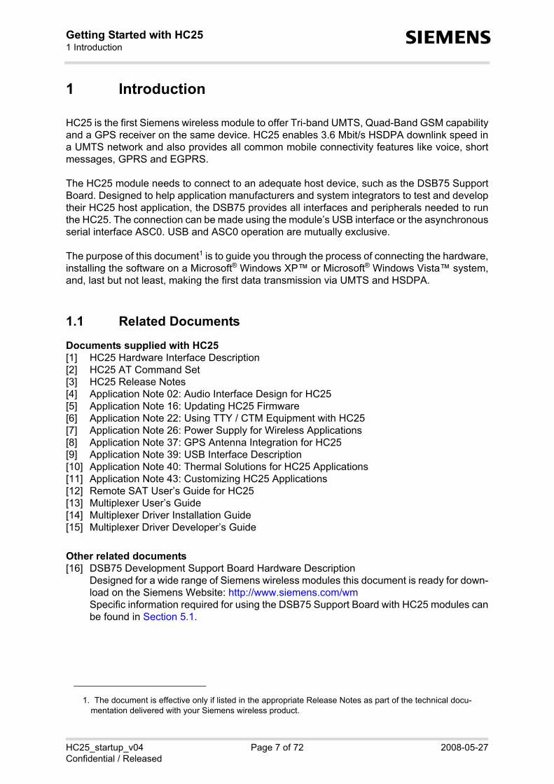
HC25 is the first Siemens wireless module to offer Tri-band UMTS, Quad-Band GSM capabilityand a GPS receiver on the same device. HC25 enables 3.6 Mbit/s HSDPA downlink speed ina UMTS network and also provides all common mobile connectivity features like voice, shortmessages, GPRS and EGPRS.
The HC25 module needs to connect to an adequate host device, such as the DSB75 SupportBoard. Designed to help application manufacturers and system integrators to test and developtheir HC25 host application, the DSB75 provides all interfaces and peripherals needed to runthe HC25. The connection can be made using the module’s USB interface or the asynchronousserial interface ASC0. USB and ASC0 operation are mutually exclusive.
The purpose of this document1 is to guide you through the process of connecting the hardware,installing the software on a Microsoft® Windows XP™ or Microsoft® Windows Vista™ system,and, last but not least, making the first data transmission via UMTS and HSDPA.
1.1 Related Documents
Documents supplied with HC25[1] HC25 Hardware Interface Description[2] HC25 AT Command Set [3] HC25 Release Notes[4] Application Note 02: Audio Interface Design for HC25[5] Application Note 16: Updating HC25 Firmware[6] Application Note 22: Using TTY / CTM Equipment with HC25[7] Application Note 26: Power Supply for Wireless Applications[8] Application Note 37: GPS Antenna Integration for HC25[9] Application Note 39: USB Interface Description[10] Application Note 40: Thermal Solutions for HC25 Applications[11] Application Note 43: Customizing HC25 Applications[12] Remote SAT User’s Guide for HC25[13] Multiplexer User’s Guide[14] Multiplexer Driver Installation Guide[15] Multiplexer Driver Developer’s Guide
Other related documents[16] DSB75 Development Support Board Hardware Description
Designed for a wide range of Siemens wireless modules this document is ready for down-load on the Siemens Website: http://www.siemens.com/wmSpecific information required for using the DSB75 Support Board with HC25 modules canbe found in Section 5.1.
1. The document is effective only if listed in the appropriate Release Notes as part of the technical docu-mentation delivered with your Siemens wireless product.

HC25_startup_v04 Page 8 of 72 2008-05-27Confidential / Released
Getting Started with HC251.2 Abbreviations10
s
1.2 Abbreviations
Abbreviation Description
ASC0 Asynchronous Serial Controller. Abbreviation used for serial interface of HC25.
APN Access Point Name
CHAP Challenge Handshake Authentication Protocol
B2B Board-to-board connector
DSB75 Short for DSB75 Development Support Board
GPRS General Packet Radio Service
HSDPA High-Speed Downlink Packet Access
IP Internet Protocol
ME Mobile Equipment
MO Mobile Originated
MT Mobile Terminated
PAP Password Authentication Protocol
PDP context Packet Data Protocol context
PPP Point-to-Point Protocol
TA Terminal Adapter
TE Terminal Equipment
UDI Unrestricted Digital Information
UICC Universal Integrated Circuit Card
UMTS Universal Mobile Telecommunication System
URC Unsolicited Result Code

HC25_startup_v04 Page 9 of 72 2008-05-27Confidential / Released
Getting Started with HC252 Installation and Configuration10
s
2 Installation and Configuration
2.1 Technical Requirements for Running HC25 on DSB75
• Windows XP or Windows Vista computer, minimum USB 1.1 connector
• HC25 module
• HC25 driver package either contained in - the HC25 mass storage = delivery default for HC25 modules shipped from factory;- or in an extra ZIP file = driver update packages delivered separately. File name:
"HC25_<release>_conman_install.zip" . Please refer to Section 2.3 to decide which installation method to choose.
• If drivers from earlier HC25 releases are still installed be sure to uninstall them first. SeeSection 2.9 for drivers of HC25 Release 01.xxx and Section 2.9.4 for drivers of earlier testsamples.
• Local Administrator Privileges on the particular Windows computer are required to install,and uninstall the drivers and the Siemens HC25 Connection Manager.
• Appropriate hardware platform, for example the reference evaluation kit delivered by Sie-mens for testing and developing HC25 applications:- DSB75 Support Board providing the application interface between the HC25 USB port
and a computer's USB port as well as between the HC25 ASC0 interface and an appro-priate serial COM port on the computer.
- Adapter board for mounting the HC25 module onto the DSB75, throughout this manualgenerally referred to as HCxx-DSB75 Adapter
- 9 to 15 Volts power supply applied at the DSB75 for powering up the DSB75 and the con-nected HC25 module
- 1 mini antenna cable (50 Ohms) from the RF antenna connector (Hirose U.FL) on theHC25 module to the Hirose U.FL connector on the DSB75; 1 external RF antenna con-necting to the SMA connector of the DSB75 (product name: SMARTEQ MiniMag), bothdelivered with DSB75
- A metal plate for grounding the external RF antenna- An active or passive GPS antenna and a special GPS adapter cable with Hirose connec-
tor and female SMA connector to be connected to the module and to the active or passiveGPS antenna.
- Optional: Handset, for example Handset for Siemens products from Votronic deliveredwith DSB75
See Section 5.1 for information on the DSB75.
• USB cable
• RS-232 cable for asynchronous serial interface ASC0 (if used)
• Appropriate host application to control the USB ports under Windows, for example Hyper-terminal integrated in Windows XP.
• UICC card
• Service Provider settings for data services, such as (E)GPRS, HSDPA and, if required, alsofor UDI. For details see Section 3.10.
• Make sure to operate the HC25 always with the UICC card inserted in the card reader anda valid SIM PIN entered. This is because most AT commands require SIM PIN authentica-tion.

HC25_startup_v04 Page 10 of 72 2008-05-27Confidential / Released
Getting Started with HC252.2 Customizing HC25 Applications10
s
2.2 Customizing HC25 Applications
If you wish to customize the product and manufacturer names displayed to your end users dur-ing the installation process, by the Windows Device Manager and on the Connection Manageruser interface you can modify the required files and strings and develop a customized installa-tion utility based on InstallShield 2008. For more information please refer to [11].
2.3 Choosing the Best Installation Strategy
The sequence of the installation steps depends on where the supplied driver package islocated:1. HC25 modules shipped from factory have the driver package located on the mass storage.
Thus, the standard installation procedure is designed to be launched directly from the massstorage. Overview of installation steps: First connect the HC25 module to the DSB75 and start thecomputer (see Section 2.4). Then install the Siemens HC25 Connection Manager to pre-pare the driver installation (see Section 2.5.1 for Windows XP or Section 2.6.1 for WindowsVista). Finally install the composite device drivers (see Section 2.5.2 for Windows XP orSection 2.6.2 for Windows Vista).
2. Latest driver updates are contained in the "HC25_<release>_conman_install.zip" file, usu-ally ready for download from http://www.siemens.com/wm. If you wish to update to the lat-est driver versions, you have the following options:- Installing the drivers from the mass storage
Overview of installation steps: First uninstall the existing drivers from the Windows com-puter. Switch off or unplug the module. Switch on or replug the module. Delete all old fileslocated in the mass storage and replace them with the new files, using exactly the samedirectory tree. Switch off or unplug the module. Switch on or replug the module. Installthe Siemens HC25 Connection Manager and the composite device drivers from the massstorage. If the HC25 module is intended to be inserted into more than one device take care thatthe mass storage always contains the latest drivers.See Section 2.10.3 for details.
- Installing the drivers from any folder inside the Windows systemOverview of installation steps: First uninstall the existing drivers from the Windows com-puter. Switch off or unplug the module. Install the Siemens HC25 Connection Manager.Switch on or replug the module. Install the composite device drivers.See Section 2.10.2 for details.

HC25_startup_v04 Page 11 of 72 2008-05-27Confidential / Released
Getting Started with HC252.4 Installing the Hardware13
s
2.4 Installing the Hardware
To properly connect the HC25 module and all accessories to the DSB75 Support Board followthe steps listed below.
Note: The names of connectors, interfaces and switches given in brackets are the same asused in [16] and below in Section 5.1.
• Check that all switches of the HCxx-DSB75 Adapter and the DSB75 Support Board are setas described in Section 5.1. See also Figure 10 which shows an exploded view of all parts.
• Connect the one end of the mini antenna cable to the RF antenna connector (Hirose U.FL)located on the module's top side (the middle antenna connector). Also, connect the GPSantenna adapter cable to the GPS antenna connector (Hirose U.FL) located on the mod-ule’s top side at the right corner.
• Mount the HC25 module upside down onto the 50-pin board-to-board connector (X104) ofthe adapter board. Use the supplied M2 screws and nuts to screw the module to theadapter.
• Attach the HCxx-DSB75 Adapter to the 2x40-pin header (X101/X102) located on theDSB75. Take gentle care that all pins are aligned correctly, then press down evenly on theadapter board until it is firmly seated. Use the supplied M3 screw and bolt to secure theadapter board to the DSB75 Support Board.
• Connect the other end of the mini antenna cable to the Hirose U.FL connector (X505) of theDSB75.
• Screw the external antenna (MiniMag) into the SMA connector (X506) on the DSB75. Toimprove the antenna performance use a metal plate for grounding. The external antennashould be positioned in the center of a metal plate.
• Connect the GPS antenna adapter cable to the external of passive GPS antenna.
• Connect the Western plug of the handset to the Western jack (X502) on the DSB75.
• Connect the power cables to the red (X400 = BATT+) and black (X401 = Ground) connec-tors of the DSB75.
• Plug the USB cable to the computer's USB port and to the USB port (X110) of the DSB75.Press the IGT key (S421) of the DSB75 to switch on the HC25 module. Start your Windowscomputer.
• If the HC25 USB drivers are not yet installed on the computer you will be prompted to doso. To continue see Section 2.5 for Windows XP or Section 2.6 for Windows Vista.
Note: The RS-232 cable can be connected any time to the module’s asynchronous serial ASC0interface and to the COM1 port of the DSB75 (the middle connector X201). Yet, keep in mindthat, by factory default, the HC25 module is prepared for use as composite USB device on aWindows XP or Windows Vista system. Therefore, please refer to Section 2.11 for details ofhow to configure HC25 either for ASC0 or USB usage.

HC25_startup_v04 Page 12 of 72 2008-05-27Confidential / Released
Getting Started with HC252.4 Installing the Hardware13
s
Figure 1: DSB75 Support Board with mounted adapter board and mini antenna cable
COM1 (X201) for ASC0
USB connector (X110)
Power supply (X400/X401
DSB75 Support Board
Mini antenna cable
Adapter board
50-pin board-to-board connector (X104)
Hirose U.FL connector(X505)SMA connector (X506)
UICC/SIM reader (X503)Western jack for handset (X502)
IGT key (left, S421) and EMERG_OFF key (right, S420)

HC25_startup_v04 Page 13 of 72 2008-05-27Confidential / Released
Getting Started with HC252.4 Installing the Hardware13
s
Figure 2: DSB75 Support Board with HC25 module and accessories connected

HC25_startup_v04 Page 14 of 72 2008-05-27Confidential / Released
Getting Started with HC252.5 Installation on Windows XP15
s
2.5 Installation on Windows XP
2.5.1 Installing Siemens HC25 Connection Manager and Preparing Driver Installation on Windows XP
After switching on or plugging the module, you will see the New Hardware Found Wizard com-ing up three times, requesting you to install the software for HC25 VCOM, HC25 NET andHC25 Modem. Click Cancel in each dialog.
At the same time the module enumerates as mass storage device in your Windows XP system,showing up as a Removable Disk assigned to the next free drive in the Windows Explorer. Anadditional Windows taskbar icon also indicates the mass storage device.
The wizard’s error message that pops up in the Windows taskbar shall be ignored. The instal-lation will proceed automatically. Note: If the installation fails to start automatically after you have canceled the three New Hard-ware Found Wizards simply navigate to the mass storage drive (= Removable Disk in the Win-dows Explorer) and double-click the provided “autorun.exe“ file.

HC25_startup_v04 Page 15 of 72 2008-05-27Confidential / Released
Getting Started with HC252.5 Installation on Windows XP15
s
Please wait a brief moment, then press Install to start the installation of the Siemens HC25Connection Manager.
The progress of the installation will be indicated as illustrated below.
Now the installation of the Siemens HC25 Connection Manager, and the driver software for thecomposite device is preinstalled. The last installation dialog closes automatically.
See Section 2.5.2 to continue.

HC25_startup_v04 Page 16 of 72 2008-05-27Confidential / Released
Getting Started with HC25 38
s
2.5.2 Installing USB and Ethernet Drivers on Windows XP
HC25 will be installed as a composite device that comprises three virtual devices, one by oneadded to your Windows XP system:• Siemens HC25 USB Com Port driver• Siemens HC25 Wireless Ethernet Adapter driver• Siemens HC25 HSDPA USB Modem driver
During the installation, the HC25 USB interface will be assigned two virtual COM ports, one forthe virtual modem port and one for the virtual application port. Windows will automatically allo-cate the next available COM port to each virtual interface.
Once the Siemens HC25 Connection Manager installation has completed Windows detects theHC25 as a new USB composite device.
The Found New Hardware Wizard willstart. Click Next to proceed with theinstallation of the "Siemens HC25 USBCom Port".
The progress of the driver installation isindicated.
Click Finish to complete the installation of the "Siemens HC25 USB Com Port".

HC25_startup_v04 Page 17 of 72 2008-05-27Confidential / Released
Getting Started with HC25 38
s
Now the installation of the "SiemensHC25 Wireless Ethernet Adapter"will start. Click Next.
The progress of the driver installa-tion is indicated.
Press Finish to complete the "Sie-mens HC25 Wireless EthernetAdapter" installation.

HC25_startup_v04 Page 18 of 72 2008-05-27Confidential / Released
Getting Started with HC25 38
s
Now the installation of the "SiemensHC25 HSDPA USB Modem" willstart. Click Next.
The progress of the driver installa-tion is indicated.
Press Finish to complete the "Sie-mens HC25 HSPDA USB Modem"installation.
At this point the installation of allthree virtual devices is completed.Windows XP notifies you that thehardware is ready to use.
HC25_startup_v04 Page 19 of 72 2008-05-27Confidential / Released
Getting Started with HC252.6 Installation on Windows Vista38
s
2.6 Installation on Windows Vista
2.6.1 Installing Siemens HC25 Connection Manager and Preparing Driver Installation on Windows Vista
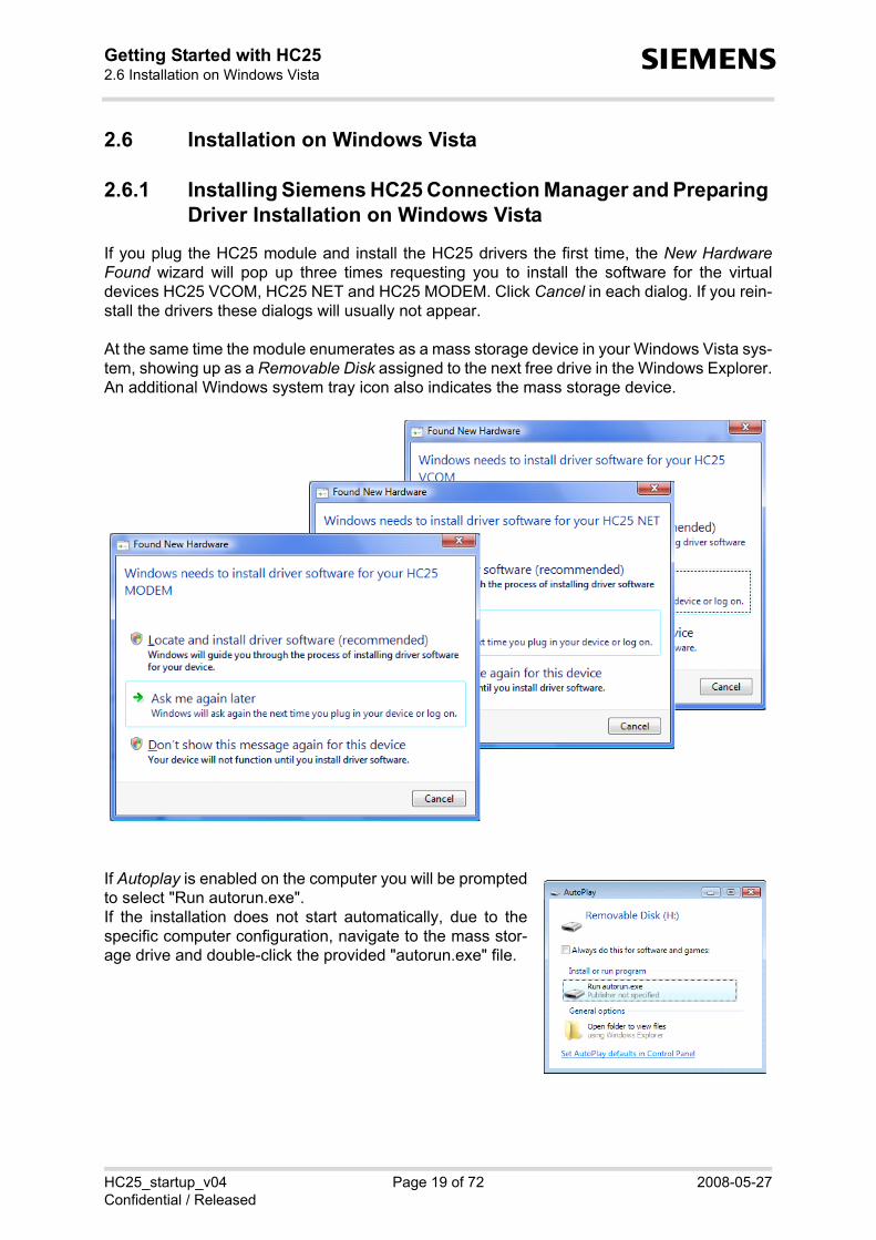
If you plug the HC25 module and install the HC25 drivers the first time, the New HardwareFound wizard will pop up three times requesting you to install the software for the virtualdevices HC25 VCOM, HC25 NET and HC25 MODEM. Click Cancel in each dialog. If you rein-stall the drivers these dialogs will usually not appear.
At the same time the module enumerates as a mass storage device in your Windows Vista sys-tem, showing up as a Removable Disk assigned to the next free drive in the Windows Explorer.An additional Windows system tray icon also indicates the mass storage device.
If Autoplay is enabled on the computer you will be promptedto select "Run autorun.exe". If the installation does not start automatically, due to thespecific computer configuration, navigate to the mass stor-age drive and double-click the provided "autorun.exe" file.

HC25_startup_v04 Page 20 of 72 2008-05-27Confidential / Released
Getting Started with HC252.6 Installation on Windows Vista38
s
The autorun.exe icon starts to blink in the task bar of Windows Vista while showing this mes-sage:
"autorun.exe is requesting your permission"
Please click on the icon. A popup window "User Account Control" will show: "An unidentifiedprogram wants access to your computer". Please press "Allow" to start the HC25 installer onWindows Vista.
The installer will start to pre-pare the installation.
Now the Siemens HC25Connection Manager can beset up. Press Install.

HC25_startup_v04 Page 21 of 72 2008-05-27Confidential / Released
Getting Started with HC252.6 Installation on Windows Vista38
s
The progress of the installa-tion is indicated.
The Siemens HC25 Connec-tion Manager setup is com-pleted. The last installationdialog box closes automati-cally.See Section 2.6.2 to con-tinue.

HC25_startup_v04 Page 22 of 72 2008-05-27Confidential / Released
Getting Started with HC252.6 Installation on Windows Vista38
s
2.6.2 Installing USB and Ethernet Drivers on Windows Vista
Once the Siemens HC25 Connection Manager installation has completed the HC25 will be setup as a composite device comprising three virtual devices:• Siemens HC25 USB Com Port driver• Siemens HC25 Wireless Ethernet Adapter driver• Siemens HC25 HSDPA USB Modem driver
An icon will show up in the Windows Vistatask bar to indicate the progress of the driverinstallation.
Finally, the icon indicates that all devices areready to use.

HC25_startup_v04 Page 23 of 72 2008-05-27Confidential / Released
Getting Started with HC252.7 Special Installation Notes38
s
2.7 Special Installation Notes
If the installation does not work as expected, additional steps may be required, usually depend-ing on the configuration of the Windows XP or Windows Vista computer.
HC25 does not show up as removable disk• If the HC25 is not visible as removable disk
(mass storage device) when connected andswitched on the first time, it is possible thatthe computer is configured to search theInternet for Windows updates. As a result,Windows is waiting for additional useraction.
• To avoid this scenario, it is recommendedto switch off this option before trying toinstall the HC25.
Siemens HC25 Connection Manager installed, but driver installation does not start• If the Siemens HC25 Connection Manager installation completes successfully as explained
in Section 2.5.1 (Windows XP) or Section 2.6.1 (Windows Vista), but the driver installationdoes not start as shown in Section 2.5.2 (Windows XP) or Section 2.6.2 (Windows Vista),it is possible that the HC25 has failed to change from mass storage device to compositedevice functionality.
• In this case, please stop the mass storage function manually. To do so, right-click the“Removable Disk“ drive and select Eject. The installation should proceed according to Sec-tion 2.5.2 or Section 2.6.2.If the HC25 still shows up as removable device, point to the associated Windows systemtray icon, and select Stop from the resulting Safely Remove Hardware box. Then unplugand replug the USB cable.

HC25_startup_v04 Page 24 of 72 2008-05-27Confidential / Released
Getting Started with HC252.8 Installed Devices and Tools on Windows XP, Windows Vista38
s
2.8 Installed Devices and Tools on Windows XP, Windows Vista
After successful installation, the HC25 module isset up as composite device comprising the virtualdevices listed below. On Windows XP and Win-dows Vista, you can use the Device Manager tocheck that all components are properly installedand configured.
Siemens HC25 HSDPA USB Modem• AT command and data interface, also referred
to as "Modem" interface if queried using the AT^SQPORT command. • Intended particularly for HSDPA and GPRS data connections.• The virtual COM port Windows has assigned to this interface is listed in the Windows
Device Manager under Modems and under Control Panel | Phone and Modem Options.• The port number can be gathered from the property pages. This COM port can be used to
set up dial-up network connections. The bit rate set by default on the modem property pageis not relevant for USB and can be left unchanged. On the Advanced tab you can put thecommand string used to define the PDP context for your GPRS / HSDPA provider. See alsoSection 3.7.

HC25_startup_v04 Page 25 of 72 2008-05-27Confidential / Released
Getting Started with HC252.8 Installed Devices and Tools on Windows XP, Windows Vista38
s
Siemens HC25 USB Com Port• AT command interface, also referred to as "Application" interface if queried using the
AT^SQPORT command.• Mainly intended for controlling the HC25 module, for receiving URCs, also for sending,
receiving, writing and reading short messages. Not intended as data interface for HSDPAand GPRS.
• The virtual COM port Windows has assigned to this port is listed in the Device Managerunder Ports (COM&LPT).
Siemens HC25 Wireless Ethernet Adapter• Wireless network adapter intended for packet switched transmission, such as HSDPA and
(E)GPRS data connections. • Listed in the Windows Device Manager under Network adapters.• Software controlled by the Siemens HC25 Connection Manager. To open the Siemens
HC25 Connection Manager in Windows XP or Windows Vista, click Start, point to Pro-grams, select Siemens, select HC25 HSDPA USB Modem and click HC25 ConnectionManager. See Section 3.10.1 for details on how to set up a connection.

HC25_startup_v04 Page 26 of 72 2008-05-27Confidential / Released
Getting Started with HC252.9 Uninstalling Drivers and Siemens HC25 Connection Manager38
s
2.9 Uninstalling Drivers and Siemens HC25 Connection Man-ager
The steps required to remove the installed HC25 components vary depending on whether themodule switched on or off.
The procedures are almost the same for Windows XP and Windows Vista except for the minordifferences described below.
2.9.1 Uninstalling Components if HC25 Connects to Windows XP
1. Ensure that the module is connected to the computer’s USB port and switched on.
2. Close all HC25 applications, for example the Siemens HC25 Connection Manager or termi-nal program(s) connected to the virtual USB port(s).
3. Open the Control Panel. Click Add or Remove Programs and select HC25 Connection Man-ager. Press Remove to select the uninstaller of the HC25 Connection Manager and theHC25 drivers.
4. Press Yes to start the uninstaller.
5. The Siemens HC25 Connection Manager and all HC25 drivers will be removed.

HC25_startup_v04 Page 27 of 72 2008-05-27Confidential / Released
Getting Started with HC252.9 Uninstalling Drivers and Siemens HC25 Connection Manager38
s
2.9.2 Uninstalling Components if HC25 Connects to Windows Vista
1. Ensure that the module is connected to the computer’s USB port and switched on.
2. Close all HC25 applications, for example the Siemens HC25 Connection Manager or thehost application(s) connected to the virtual USB port(s).
3. Open the Control Panel. Click Programs and Features and point to the HC25 ConnectionManager. Double-click or right-click HC25 Connection Manager to start the uninstaller, thenclick Yes to confirm the resulting uninstall message.
4. A popup window named User Account Control will display the message "An unidentifiedprogram wants access to your computer". Press the Allow button to launch the uninstalleron Windows Vista.
5. Wait a brief moment until the HC25Connection Manager closes and alldrivers are removed.

HC25_startup_v04 Page 28 of 72 2008-05-27Confidential / Released
Getting Started with HC252.9 Uninstalling Drivers and Siemens HC25 Connection Manager38
s
6. The Found New Hardware wizard will pop up three times because, after driver clean-up,Windows Vista starts searching for new drivers. Press Cancel to abort the search.
In some cases, the Found NewHardware wizards may indicate"Unknown Device" instead of HC25VCOM, HC25 NET and HC25MODEM. The procedure is thesame - simply press Cancel threetimes.
7. The Siemens HC25 Connection Manager and the HC25 drivers are removed now. Only the two files files hc25usbser.sys“ and “hc25usbnet.sys are left unchanged in the..\WINDOWS\system32\drivers folder. Yet, this is no problem, as they will be overwrittennext time you re-install the drivers.

HC25_startup_v04 Page 29 of 72 2008-05-27Confidential / Released
Getting Started with HC252.9 Uninstalling Drivers and Siemens HC25 Connection Manager38
s
2.9.3 Uninstalling Components if HC25 is Disconnected
If disconnected or switched off, the HC25 module is not visible on the Windows XP or WindowsVista computer unless you enable the operating system to show hidden devices. The purposeof this section is to describe how to uninstall HC25 components in such case. The dialog boxesshow Windows Vista, but Windows XP is quite similar.
1. Remove the Siemens HC25 Connection Manager as described in Section 2.9.1. As a result, the Siemens HC25 Connection Manager software will be uninstalled, but theHC25 drivers are not.
2. Although not visible, the HC25 drivers are still blocking two virtual COM ports. To free theports hidden devices must be shown as follows: On Windows XP, open the Control Panel, click System and select the Advanced tab. On Windows Vista, open the Control Panel, select System and Maintenance, click Systemand select Advanced system settings on the left panel of the dialog box. Then press the Environment Variables button. In the resulting dialog box point to the Sys-tem variables section and press the New button. Enter the new system variable "DEVMGR_SHOW_NONPRESENT_DEVICES" and setvalue "1".

HC25_startup_v04 Page 30 of 72 2008-05-27Confidential / Released
Getting Started with HC252.9 Uninstalling Drivers and Siemens HC25 Connection Manager38
s
3. Open the Device Manager (from Control Panel). Note that if the Device Manager is alreadyopen you need to close and re-open it to update the status of the devices. From the Viewmenu select Show hidden devices.
4. All hidden virtual HC25 devices are listed now. Right-click each device, one by one, selectUninstall and confirm the resulting uninstall messages. The example shows how to uninstall the Siemens HC25 USB Com Port. The SiemensHC25 Wireless Ethernet Adapter and the Siemens HC25 HSDPA USB Modem must beuninstalled in the same way.

HC25_startup_v04 Page 31 of 72 2008-05-27Confidential / Released
Getting Started with HC252.9 Uninstalling Drivers and Siemens HC25 Connection Manager38
s
2.9.4 Uninstalling Components of HC25 00.xxx Preview Releases
The following procedures apply only to drivers of very early HC25 00.xxx releases supplied aspreview samples for testing only. These drivers were available only for Windows XP.
2.9.4.1 Uninstalling Earlier Drivers
1. Under Windows XP, open the Device Manager andselect the drivers as described in Section 2.8. Keep inmind that the drivers are listed in the Device Manageronly when the module is switched on. Right-click thedriver and, from the resulting menu, select Uninstall.
If the module is disconnected first follow the stepsprovided in Section 2.9.3 and enable the Device Man-ager to show hidden devices.
2. Under ..\WINDOWS\system32\drivers remove the two files “hcusbser.sys“ and “hcusb-net.sys“. (Please note that the newly installed HC25 drivers will now be set up as“hc25usbser.sys“ and “hc25usbnet.sys).
3. Under ..\WINDOWS\INF check for old “oem*.inf“ and “oem*.pnf“ files and remove all filesrelated to earlier customer samples.To do so, open the currently installed “oem*.inf“ file(s) and compare the content with the“hcser.inf“, “hcnet.inf“and "hcmdm.inf" supplied with the latest release. All “oem*.inf“ andassociated “oem*.pnf“ files based on information from old “hcser.inf“, “hcnet.inf“ and“hcmdm.inf“files must be removed. An easy way to compare the content of these files is checking the information given in the[Siemens] section, such as the two examples shown below:Examples:
2.9.4.2 Uninstalling Earlier Connection Manager
Old versions of the Siemens Connection Manager were installed in Windows XP under Pro-gram Files | Siemens | ConnectionManager. To uninstall the program simply remove the "con-man.exe" file.Any shortcuts and icons must be deleted manually.
[SIEMENS]%hcwwan.DeviceDesc_hc1% = hcwwan.ndi, USB\VID_0681&PID_&MI_01
[SIEMENS]%hcwwan.DeviceDesc_hc1% = hcwwan.ndi, USB\VID_05C6&PID_7001&MI_01

HC25_startup_v04 Page 32 of 72 2008-05-27Confidential / Released
Getting Started with HC252.10 Updating HC25 Drivers38
s
2.10 Updating HC25 Drivers
Driver updates are contained in a ZIP file named "HC25_<release>_conman_install.zip". TheZIP file is either delivered separately or ready for download from http://www.siemens.com/wm.
The following sections describe how to install the new drivers either from any location on a Win-dows XP computer (see Section 2.10.1) or a Windows Vista computer (see Section 2.10.2) orfrom the HC25 mass storage (see Section 2.10.3).
Before installing new drivers be sure to uninstall existing drivers as described in Section 2.9.
2.10.1 Installing Driver Update from Any Folder on Windows XP
1. Switch off the HC25 module or unplug the USB cable.2. Copy or unpack the new driver package to any folder on your Windows XP computer.
The folder tree must be the same as shown in Section 2.10.3, Figure 4. Therefore, do notcopy or unpack the files into one folder only. Recommendation: When you extract the supplied "HC25_<release>_conman_install.zip"take care to retain the folders and subfolders stored in the ZIP archive.
3. Double-click the "autorun.exe" file from the dezipped driver package.4. The installation of the Siemens HC25 Connection Manager will start and, at the same time,
the composite device driver software will be preinstalled. Simply follow the screensdescribed in Section 2.5.1. The last installation dialog closes automatically.
5. Now, switch on the HC25 module or replug the USB cable. 6. Windows will detect the HC25 module as a new device. The New Hardware Found wizard
pops up three times, prompting you to install the following devices:- Siemens HC25 USB Com Port driver- Siemens HC25 Wireless Ethernet Adapter driver- Siemens HC25 HSDPA USB Modem driverTo do so, follow the screens described in Section 2.5.2, i.e. simply press Next in each dia-log, using the option Install the software automatically (Recommended).
Keep in mind that, before the composite device drivers are installed, the HC25 enumerates asmass storage if the factory default settings of the AT^SUSB command are left unchanged(parameter <start> equals "MdmNet" and timeout <mnto> equals 10 seconds). The mass stor-age is not needed, but you may be required to take the following precautions:
- If the installation of all three drivers completes before the <mnto> timeout expires themass storage will be deactivated automatically. But as 10 seconds are typically notenough for all three drivers it is very likely that the HC25 enumerates as mass storageduring the installation. As a result, the driver installation (step 6 above) may be halted, forexample after the first (or already the second) driver was set up. Yet, this is nothing toworry about - all you need to do is manually ejecting the mass storage. So, right-click theRemovable Disk drive inside the Windows Explorer and select Eject. This will deactivatethe mass storage functionality, and at the same time, cause the New Hardware Foundwizards for the next one or two drivers to pop up.
- If you prefer to install driver updates always from a location other than the HC25 massstorage, you can disable the <mnto> timeout of the AT^SUSB command (set 0 seconds).The setting is non-volatile. For details on AT^SUSB please refer to [2].
IMPORTANT: To avoid mixing up the driver packages located in the mass storage and in anyother folder be sure to run the "autorun.exe" only from the new dezipped driver package.

HC25_startup_v04 Page 33 of 72 2008-05-27Confidential / Released
Getting Started with HC252.10 Updating HC25 Drivers38
s
2.10.2 Installing Driver Update from Any Folder on Windows Vista
1. Switch off the HC25 module or unplug the USB cable.2. Copy or unpack the new driver package to any folder on your Windows XP computer.
The folder tree must be the same as shown in Section 2.10.3, Figure 4. Therefore, do notcopy or unpack the files into one folder only. Recommendation: When you extract the supplied "HC25_<release>_conman_install.zip"take care to retain the folders and subfolders stored in the ZIP archive.
3. Double-click the "autorun.exe" file from the dezipped driver package.4. The installation of the Siemens HC25 Connection Manager will start and, at the same time,
the composite device driver software will be preinstalled. Simply follow the screensdescribed in Section 2.6.1. The last installation dialog closes automatically.
5. Now, switch on the HC25 module or replug the USB cable. 6. The installation of the composite device drivers continues automatically as described in
Section 2.5.2.
On Windows Vista, the 10s timeout <mnto> of the AT^SUSB command will often be sufficientfor the composite device driver installation, eliminating the need for HC25 to temporarily enu-merate as mass storage. However, if 10 seconds are not enough, the HC25 enumerates asmass storage, and the driver installation (step 6 above) may be halted as explained in Section2.10.1 for Windows XP. In this case, manually eject the mass storage. To do so, right-click theRemovable Disk drive inside the Windows Explorer and select Eject. This will deactivate themass storage functionality, and the installation will proceed.
If you prefer to install driver updates always from a location other than the HC25 mass storage,you can disable the <mnto> timeout of the AT^SUSB command (set 0 seconds). The setting isnon-volatile. For details on AT^SUSB please refer to [2].
IMPORTANT: To avoid mixing up the driver packages located in the mass storage and in anyother folder be sure to run the "autorun.exe" only from the new dezipped driver package.

HC25_startup_v04 Page 34 of 72 2008-05-27Confidential / Released
Getting Started with HC252.10 Updating HC25 Drivers38
s
2.10.3 Installing Driver Update from HC25 Mass Storage
To ensure that the driver update installation can be started from the mass storage of the HC25we recommend to follow the steps listed below. By this approach, the factory settings of theAT^SUSB command can be left unchanged: parameter <start> equals "MdmNet" and timeout<mnto> equals 10s.
1. Uninstall the drivers and the Siemens HC25 Connection Manager as described in Section2.9.
2. Switch off or unplug the module, then switch on or replug the module. 3. Abort the installer if started automatically (press Cancel in all three New Hardware Found
wizards).4. Because no installed drivers are found (within the above AT^SUSB timeout <mnto>), the
HC25 module enumerates as mass storage, usually showing up as Removable Diskassigned to the next free drive of the Windows Explorer. Navigate to this drive and deleteall existing files, folders and subfolders containing the old driver package (see Figure 3).
Figure 3: Deleting obsolete HC25 driver files, folders and subfolders

HC25_startup_v04 Page 35 of 72 2008-05-27Confidential / Released
Getting Started with HC252.10 Updating HC25 Drivers38
s
5. Copy or unpack the new driver package to the mass storage drive. The folder tree must be the same as shown below. Therefore, do not copy or unpack thefiles into one folder only. Recommendation: When you extract the supplied "HC25_<release>_conman_install.zip"take care to retain the folders and subfolders stored in the ZIP archive.
Figure 4: Folder tree of HC25 driver package
6. Close the Windows Explorer and switch off or unplug the HC25 module.
Now the module is prepared for easy installation from the mass storage. You can switch on orreplug the HC25 module any time and proceed as described in Section 2.5 for Windows XP orSection 2.6 for Windows Vista.

HC25_startup_v04 Page 36 of 72 2008-05-27Confidential / Released
Getting Started with HC252.11 Configuring the HC25 for Operation via ASC0 or USB38
s
2.11 Configuring the HC25 for Operation via ASC0 or USB
ASC0 and USB operation are mutually exclusive: ASC0 usage disables access to the virtualUSB devices and, vice versa, USB usage disables access to the ASC0 interface. The com-mand AT^SUSB="Startup",<start> determines which mode to use.
By factory default, the HC25 is prepared for use as a composite USB device connected to aWindows XP or Windows Vista system. This requires the supplied HC25 USB compositedevice driver package to be installed as described in this manual.
Therefore, if your host application is designed to communicate with HC25 through the ASC0interface you will initially need a Windows XP or Windows Vista environment with the HC25USB composite device driver package installed. This system may be used to change the "Star-tup" settings of AT^SUSB and reconfigure the HC25 modules for use on ASC0.
Of course, if configured for ASC0, HC25 modules can be connected to systems that have noHC25 USB drivers installed.
In a Windows XP or Windows Vista environment with installed HC25 USB drivers and pluggedUSB cable the HC25 will enumerate as USB composite device even though configured forASC0. Despite that the virtual USB devices cannot be used.
Updating the HC25 firmware via the ASC0 interface requires that the USB cable is discon-nected. For details see [5].
For ASC0 operation the host application or Terminal program must have RTS/CTS flow controlenabled. The module is permanently configured for AT\Q3.
ASC0 is permanently configured for 115200 bps bit rate. Other values selectable with AT+IPRexist only for compatibility reasons, but do not take effect if set.
AT^SUSB="Startup"^SUSB: "Startup","MdmNet"OK
Read the current configuration.Response: On power-up HC25 enumerates asUSB composite device (delivery default).
AT^SUSB="Startup","None"^SUSB: "Startup","None"OKAT^SMSOOK
Configure HC25 for ASC0 operation: The set-ting "None" means that on power-up only theASC0 interface will be accessible.Switch off HC25 to make the changes takeeffect.

HC25_startup_v04 Page 37 of 72 2008-05-27Confidential / Released
Getting Started with HC252.11 Configuring the HC25 for Operation via ASC0 or USB38
s
2.11.1 Installing a Modem on the ASC0 Interface
If you wish to install a modem on the ASC0 interface you may either use the“Standard 19200 bps Modem“ integrated in Windows, or the HC25 specific serial modem deliv-ered together with HC25. The delivery only includes an INF file named "HC25genmdm.inf".
This section summarizes the basic steps for installing the HC25 modem on a Windows XPcomputer. Those for Windows Vista are similar.
Click on Start, select Settings | Control Panel | Phone and Modem Options | Modems and pressthe Add button. Select the COM port the module’s ASC0 interface is connected to on your Win-dows computer. Keep in mind that the terminal program or host application connected to thisCOM port must be disconnected during the installation, otherwise it will not be visible in the listof selectable COM ports.
The Add Hardware Wizard opens. Check the option Don't detect my modem; I will select it froma list and click Next.
The resulting list of manufacturers and models can be ignored, simply press the Have Disk but-ton and navigate to the source drive where the "HC25genmdm.inf" file is located.

HC25_startup_v04 Page 38 of 72 2008-05-27Confidential / Released
Getting Started with HC252.11 Configuring the HC25 for Operation via ASC0 or USB38
s
After the installation has completed make sure that the port speed on the Modem property pageis set to 115200 bps. In the Windows Device Manager the modem will be listed as "SiemensHC25 Standard Modem".
The steps required to configure the modem for dial-up connections are the same as for all othermodems and can be found in Section 4.1.

HC25_startup_v04 Page 39 of 72 2008-05-27Confidential / Released
Getting Started with HC253 Using the HC25 Module53
s
3 Using the HC25 Module
This chapter first provides an overview of all available HC25 interfaces. The second part showsthe basic steps required to register to the network, to select UMTS mode or GSM mode and toattach to HSDPA or GPRS.
The examples are based on a UICC card provisioned by the German network operatorT-Mobile. The used UICC card is capable of UMTS and GSM and enables the subscriber toswitch back and forth between both networks.
3.1 AT Command Interfaces
HC25 features two interfaces for processing AT commands: • Modem interface and • Application interface.
Both AT command interfaces can be assigned to the various physical and virtual interfaces ofHC25. Basically, their allocation is dependent on whether the HC25 is configured for operationthrough its asynchronous serial interface ASC0, or as USB composite device comprising twovirtual COM ports and a virtual wireless Ethernet adapter. ASC0 and USB operation are mutu-ally exclusive: ASC0 usage disables access to the virtual USB devices and, vice versa, USBusage disables access to the ASC0 interface. The command AT^SUSB="Startup",<start>determines which mode to use. Please refer to Section 2.11 (this manual) and to [2] for detailson AT^SUSB.
The following sections summarize the functions of the Modem interface and the Applicationinterface as well as their allocation to the module's physical and virtual interfaces. For greaterdetail refer to [2], especially the sections "AT Command Interpreter" and "Unsolicited ResultCode Presentation", the configuration command AT^SCFG with the feature "URC/DstIfc", <udi>and the AT+CMUX command.
To easily identify both interfaces you can use the AT^SQPORT command.
Figure 5: Interfaces available with factory default settings
Mobile Core
AT Command Interpreter
ApplModem
GPS Engine
USB Modem
USB NET
NET
USB Composite Device(AT^SUSB=“Startup“,“MdmNet“)
USB VCOM
HC25_startup_v04 Page 40 of 72 2008-05-27Confidential / Released
Getting Started with HC253.1 AT Command Interfaces53
s
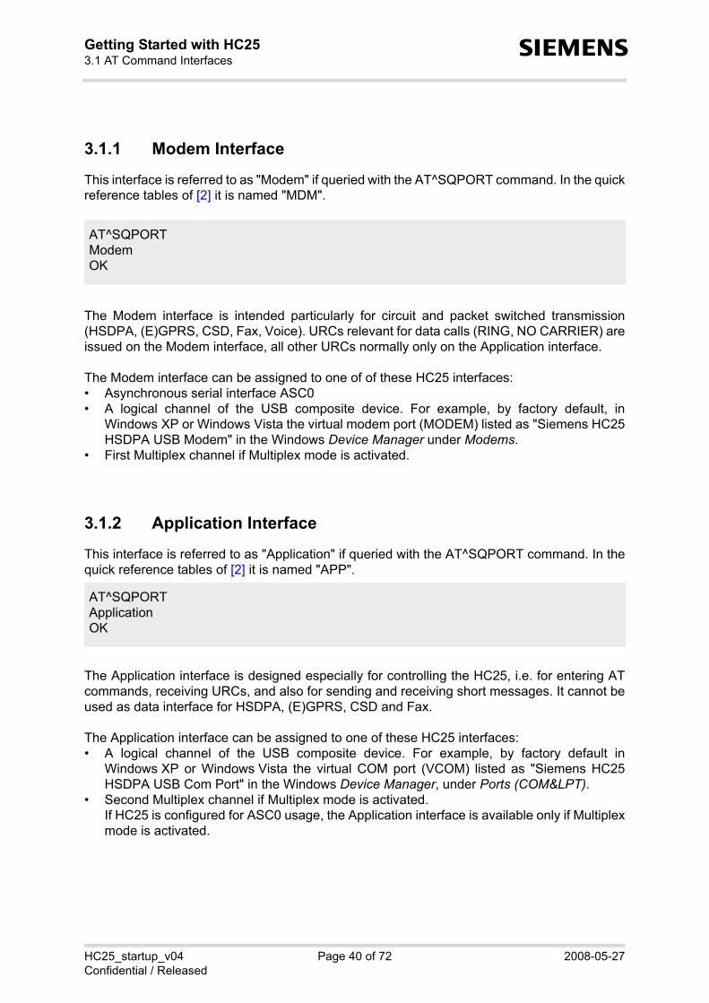
3.1.1 Modem Interface
This interface is referred to as "Modem" if queried with the AT^SQPORT command. In the quickreference tables of [2] it is named "MDM".
The Modem interface is intended particularly for circuit and packet switched transmission(HSDPA, (E)GPRS, CSD, Fax, Voice). URCs relevant for data calls (RING, NO CARRIER) areissued on the Modem interface, all other URCs normally only on the Application interface.
The Modem interface can be assigned to one of of these HC25 interfaces:• Asynchronous serial interface ASC0• A logical channel of the USB composite device. For example, by factory default, in
Windows XP or Windows Vista the virtual modem port (MODEM) listed as "Siemens HC25HSDPA USB Modem" in the Windows Device Manager under Modems.
• First Multiplex channel if Multiplex mode is activated.
3.1.2 Application Interface
This interface is referred to as "Application" if queried with the AT^SQPORT command. In thequick reference tables of [2] it is named "APP".
The Application interface is designed especially for controlling the HC25, i.e. for entering ATcommands, receiving URCs, and also for sending and receiving short messages. It cannot beused as data interface for HSDPA, (E)GPRS, CSD and Fax.
The Application interface can be assigned to one of these HC25 interfaces:• A logical channel of the USB composite device. For example, by factory default in
Windows XP or Windows Vista the virtual COM port (VCOM) listed as "Siemens HC25HSDPA USB Com Port" in the Windows Device Manager, under Ports (COM&LPT).
• Second Multiplex channel if Multiplex mode is activated.If HC25 is configured for ASC0 usage, the Application interface is available only if Multiplexmode is activated.
AT^SQPORTModemOK
AT^SQPORTApplicationOK

HC25_startup_v04 Page 41 of 72 2008-05-27Confidential / Released
Getting Started with HC253.1 AT Command Interfaces53
s
3.1.3 AT Command Interpreter
Both the Modem interface and the Application interface are handled by the same AT commandinterpreter. As a result, AT commands entered on both interfaces are not executed in parallelbut sequentially, one after the other. So, an AT command issued on one interface will be buff-ered on this interface to be executed after the other interface has completed processing earlierAT command(s).
When a dial-up connection is established over the Modem interface, the Application interfacecan be used simultaneously for any control functions. This eliminates the need for the user toenter AT commands, such as +++ and ATO, to switch back and forth between command andonline mode when working on one interface only. Yet, it should be noted that the dial-up con-nection disables the echo on both interfaces, due to the initialization strings typically set bymodems. The echo can be re-activated by executing ATE1.
If ASC0 operation is enabled all communication between HC25 and the host application takesplace only on the Modem interface. Therefore, Multiplex mode is recommended to have theApplication interface available for control functions.

HC25_startup_v04 Page 42 of 72 2008-05-27Confidential / Released
Getting Started with HC253.1 AT Command Interfaces53
s
3.1.4 Multiplex Mode
Multiplex mode according to GSM 07.10 and 3G TS 27.010 enables a serial interface to be par-tioned into virtual channels. It can be used either on the USB interface or on the asynchronousserial interface ASC0 of the HC25 module.
Multiplex mode can be started only on the Modem interface. This may be either the ASC0 inter-face or the virtual modem port of the USB composite device.
In either case, the Modem interface will be mapped to the first Multiplex channel, and the Appli-cation interface will be mapped to the second multiplex channel. As a result, the functions ofthe first and second multiplex channel are the same as described in sections 3.1.1 through3.1.3 for the Modem interface and the Application interface.
The third multiplex channel is reserved for GPS and will be used to output NMEA data if theGPS receiver is switched on and NMEA output is enabled with AT^SGPSS.
If you are using the demo driver WinMux supplied with HC25 for Windows XP and WindowsVista note that each multiplex channel will be assigned a virtual COM port of its own.
Figure 6: Interfaces available in Multiplex mode either on ASC0 or USB
ASC0 (AT^SUSB=“Startup,“None“)
Mobile Core
AT command interpreter
Multiplexer (AT+CMUX=0)
ApplModem NMEA
GPS EngineMobile Core
AT Command Interpreter
Multiplexer (AT+CMUX=0)
ApplModemNMEA
GPS Engine
USB Modem
USB NET
NET
USB Composite Device(AT^SUSB=“Startup“,“MdmNet“)

HC25_startup_v04 Page 43 of 72 2008-05-27Confidential / Released
Getting Started with HC253.1 AT Command Interfaces53
s
3.1.5 Handling of Unsolicited Result Codes
URCs are normally indicated only on the Application interface, no matter whether the Modeminterface or the Application interface was used to send the AT commands for activating theirpresentation. This URC management scheme is the default configuration recommended for atypical HC25 application. If you wish to change the default configuration please carefully readthe section "Unsolicited Result Code Presentation" in [2] and the description of the AT^SCFGfeature "URC/DstIfc", <udi>. The examples below reflect the default settings.
Default for URC routing on USB composite device:
If the Modem interface is assigned to ASC0 and Multiplex mode is not enabled, HC25 automat-ically changes the "URC/DstIfc" configuration such that all URCs will be routed to the Modeminterface. Default for URC routing on ASC0:
With Multiplex mode activated on the ASC0 interface, the default destination interface for URCswill automatically be set to "app", i.e. the Application interface (the second Multiplex channel inthis case) will be used for URC presentation.
AT^SUSB="Startup"^SUSB: "Startup","MdmNet"OK
AT^SCFG="URC/DstIfc"^SCFG: "URC/DstIfc","app"OK
Check startup mode of HC25.Response: HC25 is used as USB compositedevice.
Check which interface is used to output URCs.Response: URCs will be output on the Applica-tion interface.
AT^SCFG="Startup"^SUSB: "Startup","None"OK
AT^SCFG="URC/DstIfc"^SCFG: "URC/DstIfc","mdm"OK
Check startup mode of HC25.Response: ASC0 usage enabled, USB usagedisabled.
Check which interface is used to output URCs.Response: URCs will be output on Modeminterface.

HC25_startup_v04 Page 44 of 72 2008-05-27Confidential / Released
Getting Started with HC253.2 Switching on the HC2553
s
3.2 Switching on the HC25
The HC25 can be started by activating the IGT line. If the HC25 connects to the DSB75 pressthe IGT key (S421) or plug in the USB cable. Please wait approximately 2 seconds before usingthe module, for example before entering AT commands.
For further information please refer to Section 5.1.7.
3.3 Switching off the HC25
To shut down the HC25 module, enter the AT^SMSO command. This enables the ME to saveall data and perform an orderly shutdown.
The HC25 module can also be switched off by using the IGT line as described in [2], SectionAT^SCFG and in [1], Section "Configuring the IGT Line for Use as ON/OFF Switch").
For further information please refer to Section 5.1.7.
3.4 Registering to the Network
Make sure to operate the HC25 always with the UICC card inserted in the card reader and avalid SIM PIN entered. This is because most AT commands require SIM PIN authentication.Write command: AT+CPIN=<pin>[, <new pin>]
AT^SMSOOK
The ME switches off.
AT+CPIN?+CPIN: SIM PINOKAT+CPIN=“1234“OKAT+CPIN?+CPIN: READYOK
Entering the SIM PIN.

HC25_startup_v04 Page 45 of 72 2008-05-27Confidential / Released
Getting Started with HC253.5 Selecting UMTS or GSM53
s
3.5 Selecting UMTS or GSM
The GSM 07.07 operator selection command AT+COPS has been enhanced to enable thesubscriber to select whether to use UMTS or GSM. You can quickly switch back and forthbetween both network types while the ME remains registered.
Write command: AT+COPS=<mode>[, <format>[, <oper>[, <act>]]]
The parameter <act> (access technology) can take the values listed below. The parameter isstored non-volatile.0 GSM network2 UMTS network
Note: By factory default, an automatic network selection mode is set which enables the ME toselect either UMTS or GSM, depending on the network coverage. This automatic moderemains enabled until you explicitly set either UMTS or GSM using the <act> parameter ofAT+COPS. Setting the <act> parameter forces the ME to select either UMTS only or accord-ingly, GSM only. If the specified network is not available, the network registration will be dis-abled. Setting <mode> to 0 without choosing a specific <act> enables the automatic selectionmode once again.
Furthermore, the command AT+COPS serves to query or specify several modes of selectingthe GSM network operator. These functions are not discussed in this document.
AT+COPS?+COPS: 0,0,"T-Mobile D",2
OK
Querying the current network mode.The ME is registered to the German opera-tor T-Mobile and uses UMTS.
AT+COPS=0,,,0 #(or AT+COPS=,,,0)OKAT+COPS?+COPS: 0,0,"T-Mobile D",0
OK
AT+COPS=0,,,2 #(or AT+COPS=,,,2)OKAT+COPS?+COPS: 0,0,"T-Mobile D",2
OK
AT+CPIN?+CPIN: READY
OK
Selecting the GSM network.
Query the current network type.The response confirms that the ME haschanged to the GSM network.
Selecting the UMTS network.
There is no need to enter the SIM PINagain.
AT+COPS=0OK
Setting automatic network selection modewithout specifying <act>.

HC25_startup_v04 Page 46 of 72 2008-05-27Confidential / Released
Getting Started with HC253.6 Attaching to the HSDPA or (E)GPRS Network53
s
3.6 Attaching to the HSDPA or (E)GPRS Network
The HC25 can be configured whether to try automatically to attach to the HSDPA or (E)GPRSnetwork immediately after registering to the UMTS or GSM network. To set your preferencesuse the "GPRS/AutoAttach" parameter of the AT^SCFG command.
3.7 Defining the PDP Context for HSDPA or (E)GPRS Network
Use the AT+CGDCONT command to configure the correct provider settings. The PDP contextis stored non-volatile.
Write command:AT+CGDCONT=<cid>[, <PDP_type>[, <APN>[, <PDP_addr>]]]
The focus of this document is only on the parameters <cid>, <PDP_type> and <APN>. Thestring parameters must be enclosed in quotation marks.
Under Windows XP and Windows Vista, the PDP context can, optionally, be entered on theModem property page as described in Section 2.8.
AT^SCFG="GPRS/AutoAttach",enabled^SCFG: "GPRS/AutoAttach","enabled"OK
Configuring HC25 to try automatically to attachto the HSDPA or (E)GPRS network.
AT+CPIN=1234OK+CREG: 1
Entering the PIN.
HC25 is properly registered to the network.
AT+CGATT?+CGATT: 1
OK
Querying the current service state.The ME is attached. Depending on theselected network type (see AT+COPS), it iseither attached to the HSDPA or GPRS ser-vice.
AT+CGDCONT=1,"IP","internet.t-mobile"OK
AT+CGDCONT?+CGDCONT: 1,"IP","internet.t-mobile","",0,0OK
Specifying the PDP context (example showsthe APN of the German network provider T-Mobile).
Checking the current PDP context definition.

HC25_startup_v04 Page 47 of 72 2008-05-27Confidential / Released
Getting Started with HC253.8 Making a Voice Call (MO)53
s
3.8 Making a Voice Call (MO)
The commonly used GSM 07.07 dialing command ATD is fully applicable both in the UMTSand the GSM network.
To make a mobile originated voice call enter ATD, type the destination number and add a semi-colon. The result code OK will be returned immediately after dialing, prior to call setup.
To end the call, use the AT+CHUP command (ATH is for data calls only).
3.9 Answering a Voice Call (MT)
A mobile terminated voice call is indicated by the RING URC. To answer the call, enter ATA.
To terminate the call use AT+CHUP.
ATD030111111111;OKat+clcc+CLCC:1,0,0,0,0,"030111111111",129,"Tom"
AT+CHUPOK
at+clccOK
The HC25 subscriber makes a voice call.
Checking the call status (MO call is active).
The HC25 subscriber terminates the call.
Checking the call status (no call).

HC25_startup_v04 Page 48 of 72 2008-05-27Confidential / Released
Getting Started with HC253.10 HSDPA or GPRS Data Transfer53
s
3.10 HSDPA or GPRS Data Transfer
HC25 offers two ways to access the GPRS or HSDPA networks: • the Siemens HC25 Connection Manager provided for the Siemens HC25 Wireless Ethernet
Adapter. The program is part of the HC25 driver package. See Section 3.10.1.• a dial-up network connection via the installed Siemens HSDPA USB Modem as described
in Section 3.10.2.
Contact your service provider to obtain the appropriate settings for access to the (E)GPRS andHSDPA services, as a rule the following:• APN (network operator specific Name of Access Point that connects the GSM network to
the Internet)• Primary and secondary DNS• Static IP address or DHCP• QoS settings• User name and password
Before trying to connect to the data services make sure that the module is registered to the net-work. To take advantage of HSDPA the <act> parameter of AT+COPS shall equal "2". For(E)GPRS the parameter shall be "0".
The SIM PIN can be entered from the host application using the AT+CPIN command. As analternative to this, the SIM property page of the Siemens HC25 Connection Manager can beused for entering the PIN unless already done from the host application.

HC25_startup_v04 Page 49 of 72 2008-05-27Confidential / Released
Getting Started with HC253.10 HSDPA or GPRS Data Transfer53
s
3.10.1 Data Transfer via Siemens HC25 Connection Manager
3.10.1.1 Opening and Closing Siemens HC25 Connection Manager
To open the Siemens HC25 Connection Manager in Windows XP or Windows Vista, click Start,point to Programs, select Siemens, select HC25 HSDPA USB Modem and click HC25 Connec-tion Manager.
The Siemens HC25 Connection Manager can be opened only when the HC25 module isswitched on. This implies to close the Siemens HC25 Connection Manager before switching offor restarting the HC25 module. Otherwise, the following warning message will appear, forexample, when you restart the HC25 module although the Siemens HC25 Connection Man-ager is still open.
3.10.1.2 Revision History of Siemens HC25 Connection Manager
The SIM property page described in Section 3.10.1.3 is available as of Version 1.4.00 of theSiemens HC25 Connection Manager.
For earlier versions of the Siemens HC25 Connection Manager up to version 1.3.01 WindowsVista users were required to log on as administrator. As of Version 1.4.00 this is no longer nec-essary.

HC25_startup_v04 Page 50 of 72 2008-05-27Confidential / Released
Getting Started with HC253.10 HSDPA or GPRS Data Transfer53
s
3.10.1.3 Using the Siemens HC25 Connection Manager
This section describes how to use the Siemens HC25 Connection Manager on Windows XP orWindows Vista.
Connection property page• Use the Select Device listbox to
choose the Siemens HC25 WirelessEthernet Adapter. When opened thefirst time or after disabling theadapter, the listbox may be empty.
• Check the APN Name box and enterthe APN (Access Point Name) ofyour service provider.
• If necessary, check the Authentica-tion Preference box and select thetype of authentication protocol. Oth-erwise, PAP and CHAP apply bydefault. Username and passwordare also provider dependent.
• Press the Connect button to set up aconnection. Then simply open yourInternet browser. The box on therightmost bottom represents the sig-nal strength.
• To close the connection press theDisconnect button (available whenconnected).
The Auto Connect check box on the leftmost bottom can be activated if you want the SiemensHC25 Wireless Ethernet Adapter to automatically connect to the network each time you restartthe HC25. This option can be used particularly with a flat rate subscription. In this case, takecare that the SIM PIN authentication is also done automatically.
SIM property pageThe SIM property page can be used to enter the SIM PIN, unless already done from the hostapplication.
The PIN needs to be given only once, either in the host application with AT+CPIN or on the SIMproperty page of the Siemens HC25 Connection Manager. Please note that entering the PINfrom the host application will not update the values shown on the SIM property page, althoughPIN authentication is applicable to the Siemens HC25 Connection Manager as well. The otherway round, after entering the PIN from the Siemens HC25 Connection Manager the PIN statusof the AT+CPIN command will change to "+CPIN: READY".
Use the Sim Actions group box to select a function and to enter the PIN. Press the Submit but-ton to make the action take effect. The PIN1 and PIN2 group boxes show the result of the lastaction.
You can choose to enable or disable the PIN protection. When doing so, keep in mind that theselected PIN protection mode is valid for the entire HC25 module. Therefore, any changeimplies a change to the "SC" lock settings made with AT+CLCK.

HC25_startup_v04 Page 51 of 72 2008-05-27Confidential / Released
Getting Started with HC253.10 HSDPA or GPRS Data Transfer53
s
Enable PIN protection (factory default):• Select Enable PIN protection from the Action drop-down field, type the PIN into the Pin
Value field, select Verify Pin and press the Submit button. The result is shown in the PIN1group box: Status: Pin Enabled, Not Verified. Corresponding AT+CLCK configuration:AT+CLCK="SC",1.
• From now on, you will need to enter the PIN either from the host application with AT+CPINor on the SIM property page of the Siemens HC25 Connection Manager. In the latter case,type the PIN into the Pin Value field, select Verify from the Action drop-down field and pressthe Submit button. The result is shown in the PIN1 group box: Status: Pin Enabled, Verified.
Disable PIN protection:• Select Disable PIN protection from the
Action drop-down field, enter the PINinto the Pin Value field and press theSubmit button. The result is shown inthe PIN1 group box: Status: Pin Dis-abled. Corresponding AT+CLCK con-figuration: AT+CLCK="SC",0.
• From now on, PIN authentication willbe done automatically each time yourestart the module.
HC25_startup_v04 Page 52 of 72 2008-05-27Confidential / Released
Getting Started with HC253.10 HSDPA or GPRS Data Transfer53
s
3.10.2 Data Transfer via Dial-Up Network
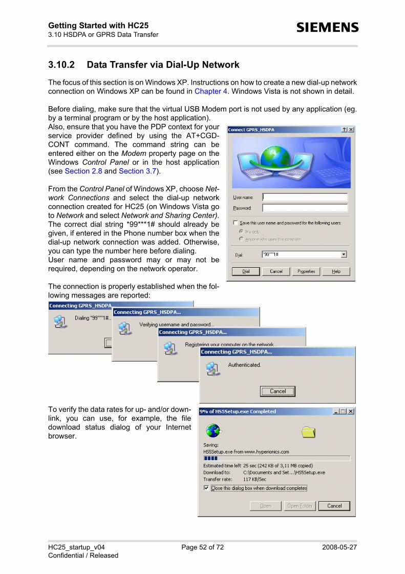
The focus of this section is on Windows XP. Instructions on how to create a new dial-up networkconnection on Windows XP can be found in Chapter 4. Windows Vista is not shown in detail.
Before dialing, make sure that the virtual USB Modem port is not used by any application (eg.by a terminal program or by the host application). Also, ensure that you have the PDP context for yourservice provider defined by using the AT+CGD-CONT command. The command string can beentered either on the Modem property page on theWindows Control Panel or in the host application(see Section 2.8 and Section 3.7).
From the Control Panel of Windows XP, choose Net-work Connections and select the dial-up networkconnection created for HC25 (on Windows Vista goto Network and select Network and Sharing Center).The correct dial string *99***1# should already begiven, if entered in the Phone number box when thedial-up network connection was added. Otherwise,you can type the number here before dialing.User name and password may or may not berequired, depending on the network operator.
The connection is properly established when the fol-lowing messages are reported:
To verify the data rates for up- and/or down-link, you can use, for example, the filedownload status dialog of your Internetbrowser.

HC25_startup_v04 Page 53 of 72 2008-05-27Confidential / Released
Getting Started with HC253.10 HSDPA or GPRS Data Transfer53
s
Terminating the dial-up network connectionTo stop a HSDPA or GPRS data connection disconnect the dial-up network connection. Thiscan be done in two ways:
1. Double-click the dial-up network connectionicon in the system tray. In the resulting con-nection status dialog press the Disconnectbutton.
2. The other way is available on the NetworkConnections page of the Control Panel: Right-click the active connection to open a contextmenu where to choose Disconnect.
3.10.2.1 Local Echo Settings
Due to the initialization strings typically set by modems, a dial-up network connection may auto-matically change the local echo settings: Opening a dial-up network connection deactivates(ATE0) and activates (ATE1) the local echo. Releasing the dial-up network connection deacti-vates the echo once again (ATE0). As Modem and Application interface are controlled from thesame AT command interpreter the change takes effect on both interfaces.
Therefore, after closing a dial-up network connection you are advised to wait a few secondsbefore entering an AT command on the Application interface. Otherwise, it is possible that theecho deactivation command ATE0 is still being executed on the Modem interface while anotherAT command is already entered on the Application interface. As a result, the AT commandresponse expected on the Application interface may appear incomplete.
Likewise, if you enter an AT command on the Application interface in parallel to a dial-up net-work connection running on the Modem interface at the time when the echo is deactivated takeinto account that the expected response may be indicated either partially or not at all.
Each time after closing a dial-up network connection you are advised to send the ATE1 com-mand to enable the local echo again.

HC25_startup_v04 Page 54 of 72 2008-05-27Confidential / Released
Getting Started with HC254 Appendix I59
s
4 Appendix I
4.1 Adding and Configuring a New Dial-Up Network Connection
This section will help you create and configure a new dial-up network connection when usingthe installed Siemens HSDPA USB Modem to access the GPRS or HSDPA network.
All step-by-step instructions and figures provided below refer to Windows XP. On WindowsVista, use the Network and Sharing Center to configure a dial-up network connection.
4.1.1 Creating a New Dial-up Network Connection
There are several ways to start creating a new dial-up network connection. For example, openthe Control Panel, double-click Network Connections, select New connection. Another way isto select Settings from the Start menu, click Network Connections, then New Connection Wiz-ard.
In any case, the Network Connection Wizard opens. Click Next to continue. Put a check markon Connect to the Internet and click Next.

HC25_startup_v04 Page 55 of 72 2008-05-27Confidential / Released
Getting Started with HC254.1 Adding and Configuring a New Dial-Up Network Connection59
s
Select the option Set up my connection manually and click Next. Select Connect using a dial-up modem and click Next.
Select the modem that you want to use for the dial-up network connection. Click Next to con-tinue. Type an appropriate Connection name and click Next.

HC25_startup_v04 Page 56 of 72 2008-05-27Confidential / Released
Getting Started with HC254.1 Adding and Configuring a New Dial-Up Network Connection59
s
In the Phone number box, put thedial string *99***1# commonlyused to access the GPRS network. Note: The number "1" addedbefore the hash determines thatthe first PDP context shall be used.The number must be identical tothe <cid> value set with AT+CGD-CONT (see Section 3.7).
Depending on the network, youmay be required to put a Username and a Password for the dial-up network connection. If notrequired, you may leave all boxesempty. Click Next.
In the resulting dialog, click Finish.This will cause the Connect… dia-log to appear (screen is shown inSection 4.1.2). Yet, at thismoment, it is recommended thatyou press Cancel in order tocheck, and if necessary, to config-ure the dial-up network connectionas described in Section 4.1.2.

HC25_startup_v04 Page 57 of 72 2008-05-27Confidential / Released
Getting Started with HC254.1 Adding and Configuring a New Dial-Up Network Connection59
s
4.1.2 Configuring a Dial-up Network Connection
Every newly created dial-up network connection should be configured before using it to estab-lish a PPP connection.
Open the Control Panel, double-click Network Connections, select the dial-up network connec-tion you want to configure. In the resulting Connect… dialog, press the Properties button.
On the General tab, select the modem you want to configure. The correct dial string *99***1#should already be given, if entered before in the Phone number box when the dial-up networkconnection was created (see Section 4.1.1).

HC25_startup_v04 Page 58 of 72 2008-05-27Confidential / Released
Getting Started with HC254.1 Adding and Configuring a New Dial-Up Network Connection59
s
Select the Security tab to verify or edit authentication options for PPP connections.
By default, Windows XP enables the optionTypical with unsecured passwords for thecommonly used but unsafe PAP authentica-tion method. As this is the minimum level ofsecurity supported in all networks the settingusually enables the subscriber to make a con-nection, though at the expense of security.
Many network operators apply more secure authentication methods for PPP connections, suchas CHAP. For access to these networks, activate the Advanced (custom setting) option andpress the Settings button. On the resulting Advanced Security Settings property page, enableor disable the authentication protocols according to the information provisioned by your serviceprovider.
Note: If an attempt to connect to a HSDPA or GPRS network fails, check that the authenticationprotocols are properly set.

HC25_startup_v04 Page 59 of 72 2008-05-27Confidential / Released
Getting Started with HC254.1 Adding and Configuring a New Dial-Up Network Connection59
s
On the Networking tab, the default settings are acceptable in most cases: The drop-down menushows PPP: Windows 95/98/NT/2000, Internet for the type of dialup server as default.
Select the Internet Protocol (TCP/IP) on the Networking tab and press the Properties button togo to the General page. In most cases, it is sufficient to accept the default settings: Obtain anIP address automatically and Obtain DNS server address automatically.Otherwise, you have to select the options Use the following IP address / Use the following DNSaddresses and specify the IP addresses provisioned by your network operator. The Advanced button opens a further property page where you can set your preferences whenworking in a local network and a dial-up network at the same time.
In the PPP settings box, verify that EnableLCP extensions and Enable software com-pression are selected and click OK.

HC25_startup_v04 Page 60 of 72 2008-05-27Confidential / Released
Getting Started with HC255 Appendix II71
s
5 Appendix II
5.1 Interface Description of DSB75 Support Board and HCxx-DSB75 Adapter
This section refers to the DSB75 Support Board and the adapter board needed to mount aHC25 module onto the DSB75 Support Board. An overview of how to install the module andconnect all accessories is provided in Section 2.4.
Please note that the DSB75 Support Board is designed for a wide range of Siemens wirelessmodules. A detailed interface description can be found in [16]. The focus of this section is onlyon the adapter board and HCxx specific information for the DSB75 Support Board.
The names of all connectors, interfaces, switches and LEDs used in [16] are also used through-out this manual, however some DSB75 pins may have different names or are not relevant forHC25.
5.1.1 Configuring the HCxx-DSB75 Adapter
Before you start installing all components check that the slide switches on your adapter boardare set as shown in Figure 7. See also Section 5.1.12 for details on MIC1 and MIC2.Please note that there are several generations of the adapter board on the market. All informa-tion provided in this manual refers to the two adapter board types "HC25/HC28-DSB75Adapter" and "HC15/HC25-DSB75 Adapter prepared for HC28". The major difference over ear-lier revisions is that both types support the asynchronous serial interface ASC0. Furthermore,the slide switches S100 and S101 are no longer mounted on the "HC25/HC28-DSB75Adapter". Throughout this manual the adapter board is named HCxx-DSB75 Adapter.
Figure 7: HCxx-DSB75 Adapter - connector pinning and slide switch settings1) S100 and S101 not mounted on adapter named HC25/HC28-DSB75 Adapter
2x40 pin header
S101
S103
S102
X104
S100
2 3
3 2
3 2
3
2
1 25
2650
139
240 X100
139
240 X101
b2b 50pin
HCxx-DSB75 Adapter
Area for the module
1)
1)
MIC
2
MIC
1

HC25_startup_v04 Page 61 of 72 2008-05-27Confidential / Released
Getting Started with HC255.1 Interface Description of DSB75 Support Board and HCxx-DSB75 Adapter71
s
5.1.2 Configuring the DSB75 Support Board
Check that all slide switches and jumpers on the DSB75 Support Board are set as shown inFigure 8.
Figure 8: DSB75 - connectors, switches, slide switch settings
X505 = RF cable connector Hirose U.FLX506 = SMA antenna connectorX100 = Do not useX503 = SIM card holderX502 = Audio interface 1 (western jack)X420, S420 = EMERG_OFFX421, S421 = IGT
X400 = Power supply connector (red) for 9V - 15VX401 = GND (black)X700, X701 = Audio interface 2X110 = USB connectorX201 = COM1 for asynchronous serial interface ASC0X202, X205 = Do not useX101, X102 = 2x40-pin header for adapter board
X202 X201 X 205
X 400X401
X110
X120
S112
S110
X121
S111
C413
X 410
X 411
X 405
C415
C414
X510
X511
X 551X 552
X122
S601
X 602
X 710 TP105
X700
S714
S715
S710
S711
V430V431
X505
X506
TP106X100
X 503X502
X501
X 500
S307
S 305S303S 301
S 300 S 302 S 304 S306S713 S712
S717 S716
S730S 731
S420
TP104
X420 X421
X 101 X102
S201 S200
X 554
X703
X550X553
X561X560X562
S504
S503S502TP501
TP502
S501S500
S 457S 452
S456
S455
S 453
S 454S 450S460
S451S 461
S462
S464
S465
S463S466S469
S459
S467
S458 S 468
1
2
3 1
2
3 1
2
3
1
10
12
3
12
3
12
3
12
3
12
3
12
3
12
3
12
3
3940
12
1
2
3 1
2
3
1
2
3 1
2
3
1
2
3 1
2
3
3
2
1 3
2
1 3
2
1 3
2
1
3
2
1 3
2
1 3
2
1 3
2
1
1
2
3
4
8
4 5 6 7
1 2 3
1 8
1
1 1
1
2
3
1 3
1 3
1 3
112
1
1
5
1
12
3
1
1
12
31
231
23
12
31
231
23
12
31
231
23
12
31
231
23
12
31
23
12
31
231
23
12
31
231
23
1
2
3
1
2
3
1
2
3
1
1
1 1
1
11
1 4 2 3
1 56 9
1 56 9
1 56 9
3940
12
1
1
1
2
2
9 10
9 10
2
9
1 2 3
4 5 6
X2031
X206X204
1
1
X 6001
DSB75
S421
(X701 bottom side)

HC25_startup_v04 Page 62 of 72 2008-05-27Confidential / Released
Getting Started with HC255.1 Interface Description of DSB75 Support Board and HCxx-DSB75 Adapter71
s
5.1.3 Connection Diagram for HC25 Evaluation Kit
Figure 9 illustrates the setup of an evalution kit for HCxx modules. The test equipment has tobe connected as shown in the figure.
Figure 9: Connection diagram for HC25 evaluation kit
5.1.4 Mounting HC25 onto DSB75
Figure 10 shows an exploded view of the DSB75 Support Board, the HCxx-DSB75 Adapter andthe connected HC25 module.
HCxxmodule
SIM
PC
+ 9 ..+ 15 V
0 VPSU
USB -cable
RF cable
Cords with banana plugs ( 4 mm )
Antenna
Handset
X505
X506
X101,X102
X503
X502
X110
X400
X401
X101,X100
X104
b 2 b
HCxx Evaluation Kit
HCxx-DSB75Adapter
DSB75 Board

Getting Started with HC255.1 Interface Description of DSB75 Support Board and HCxx-DSB75 Adapter
s
HC25_startup_v04 Page 63 of 72 2008-05-27Confidential / Released
Figure 10: Mounting HC25 to DSB75 (exploded view )

HC25_startup_v04 Page 64 of 72 2008-05-27Confidential / Released
Getting Started with HC255.1 Interface Description of DSB75 Support Board and HCxx-DSB75 Adapter71
s
5.1.5 Board-to-Board Connector
This section shows the pin assignment of the 50-pin board-to-board connector (B2B) on theHC25 module and the mating 50-pin connector X104 on the HCxx-DSB75 Adapter. The board-to-board connector on the DSB75 Support Board is not applicable.
Figure 11: B2B connector on HCxx-DSB75 Adapter (X104) and HC25 module
5.1.6 2x40 Pin Header on DSB75 Support Board and HCxx-DSB75 Adapter
Figure 12 shows the pin assignment of the 2x40 pin header on the DSB75 Support Board andthe mating connector on the HCxx-DSB75 Adapter. Each 2x40 pin header consists of two sections, referred to as X100/X101 on the HCxx-DSB75Adapter, and X101/X102 on the DSB75 Support Board. All used HC25 pins at the 50-pin board-to-board connector X104 are connected to the pinheader sections X100 and X101 on the HCxx-DSB75 Adapter. Some signal lines are con-nected to slide switches or OR jumpers or capacitors. As the DSB75 applies also to other Sie-mens wireless products the pin names are not always the same on both sides. Test points on the HCxx-DSB75 Adapter are available only at soldering pads of the 2x40 pinheader. See also Section "Test Points" in [16].
X104 on DSB75 Support BoardModule
26 GND 25 26 BATT+ 2527 GND 24 27 BATT+ 2428 GND 23 28 BATT+ 2329 GND 22 29 BATT+ 2230 GND 21 30 BATT+ 2131 Do not use 20 31 VEXT 2032 Do not use 19 32 RING0 1933 VDDLP 18 33 DSR0 1834 Do not use 17 34 RTS0 1735 USB_DN 16 35 DTR0 1636 USB_DP 15 36 RXD0 1537 VUSB 14 37 CTS0 1438 STATUS1 13 38 TXD0 1339 STATUS0 12 39 DCD0 1240 PWR_IND 11 40 EMERG_OFF 1141 GND 10 41 IGT 1042 Do not use 9 42 Do not use 943 Do not use 8 43 Do not use 844 Do not use 7 44 Do not use 745 CCGND 6 45 AGND 646 CCIN 5 46 EPN 547 CCRST 4 47 EPP 448 CCIO 3 48 MICN 349 CCVCC 2 49 MICP 250 CCCLK 1 50 VMIC 1
HC
xx-D
SB
75 A
dapt
er
1) S101 not mounted on HC25/HC28-DSB75
Adapter
X10
4
3 2
12526
50
1 )
S100
B2B
50-p
inco
nnec
tor

Getting Started with HC255.1 Interface Description of DSB75 Support Board and HCxx-DSB75 Adapter
s
HC25_startup_v04 Page 65 of 72 2008-05-27Confidential / Released
HCxx-DSB75 Adapter DSB75 Support BoardGND 39
X101
40 GND GND 40
X101
39 GNDDo not use 37 38 Do not use DAC_OUT 38 37 ADC1_INPWR_IND 35 36 Do not use PWR_IND 36 35 ADC2_INDo not use 33 34 GND TP_ENV 34 33 GNDDo not use 31 32 Do not use RXD2_GPIO9 32 31 TXD2_GPIO10Do not use 29 30 Do not use SPICS 30 29 SD_WP(GPIO8)Do not use 27 28 Do not use SD_3(GPIO4) 28 27 SPIDIDo not use 25 26 Do not use SD_2(GPIO3) 26 25 SD_DET(GPIO7)Do not use 23 24 STATUS1 SD_1(GPIO2) 24 23 SD_CMD(GPIO6)Do not use 21 22 STATUS0 SD_0(GPIO1) 22 21 SD_CLK(GPIO5)Do not use 19 20 do not use I2CDAT 20 19 I2CCLKUSB_DP 17 18 VUSB USB_DP 18 17 VUSB_INUSB_DN 15 16 do not use USB_DN 16 15 USC5
Do not use 13 14 do not use VSENSE 14 13 ISENSEVMIC 11 12 do not use VMIC 12 11 USC6EPN 9 10 CCCLK EPN2 10 9 CCCLKEPP 7 8 CCVCC EPP2 8 7 VSIMEPP 5 6 CCIO EPP1 6 5 CCIOEPN 3 4 CCRST EPN1 4 3 CCRST
MICN2 1 2 CCIN MICN2 2 1 CCINMICP2 39
X100
40 CCGND MICP2 40
X102
39 CCGNDMICP1 37 38 Do not use MICP1 38 37 USC4MICN1 35 36 Do not use MICN1 36 35 USC3AGND 33 34 Do not use AGND 34 33 USC2
IGT 31 32 Do not use IGT 32 31 USC1EMERG_OFF 29 30 Do not use EMERG_RST 30 29 USC0
DCD0 27 28 Do not use DCD0 28 27 BATTEMPDo not use 25 26 Do not use CTS1 26 25 SYNC
CTS0 23 24 Do not use CTS0 24 23 RXD1Do not use 21 22 RXD0 RTS1 22 21 RXD0
DTR0 19 20 Do not use DTR0 20 19 TXD1RTS0 17 18 TXD0 RTS0 18 17 TXD0DSR0 15 16 VDDLP DSR0 16 15 VDDLPRING0 13 14 Do not use RING0 14 13 VCHARGEVEXT 11 12 Do not use VEXT 12 11 CHARGEGATEBATT+ 9 10 GND BATT+ 10 9 GNDBATT+ 7 8 GND BATT+ 8 7 GNDBATT+ 5 6 GND BATT+ 6 5 GNDBATT+ 3 4 GND BATT+ 4 3 GNDBATT+ 1 2 GND BATT+ 2 1 GND
23
139
240
X100
139
240
2x40
pin
head
er
X101
S101
1)
1) S101 not mounted on HC25/HC28-DSB75
Adapter
HC
xx-D
SB7
5 A
dapt
er
Figure 12: 2x40 pin headers on HCxx-DSB75 Adapter and DSB75
Green: used signalsRed: unused signals

HC25_startup_v04 Page 66 of 72 2008-05-27Confidential / Released
Getting Started with HC255.1 Interface Description of DSB75 Support Board and HCxx-DSB75 Adapter71
s
5.1.7 Turn on/off a HC25 Module Connected to the DSB75
Turn on/off procedures for HC25 are described in [1]. When turning on/off the module makesure to meet the timing requirements specified in [1].
There are several ways to switch on the module: • Pressing the non-locking ignition key S421 (IGT) of the DSB75• Plugging in the USB cable to the X110 connector• Toggling the high-low state of the DTR line at the COM1 interface X201
Please note that the S420 switch is intended for emergency shutdown, not for emergency resetas described in [16] for other Siemens wireless modules.
Figure 13: On/off circuit on HCxx-DSB75 Adapter and DSB75
US
Bco
nnec
tor1
VBUS_AB
DS
UB
9R
S23
2(A
SC
0)
DTR
IGT
Jumper
JumperIgnition switch
1M
220K 2u2
X420
S421
X203
X110
X201
d/dt
PWR_IND
100k
220K 2u2
d/dt100k
JumperX120
PWR_IND enables the LED-drivers, RS232 drivers, pull-up resistors
Jumper
EMERGRE_OFF switchX421
S420
EMERG_RST30
32
36
EMERG_OFF
IGT
PWR_INDPWR_IND
11
10
40PWR_IND
IGT
EMERG_OFF
31
29
35
X101
X102X100
X101
Mod
ule
DSB75HCxx-DSB75 Adapter

HC25_startup_v04 Page 67 of 72 2008-05-27Confidential / Released
Getting Started with HC255.1 Interface Description of DSB75 Support Board and HCxx-DSB75 Adapter71
s
5.1.8 SIM Interface
Figure 14: SIM interface on HCxx-DSB75 Adapter and DSB75
5.1.9 USB Device Interface
Figure 15: USB interface on HCxx-DSB75 Adapter and DSB75
VSIMCCRST
CCIOCCCLK
CCIN
41
2637
8
CCG
ND
VSIM
CC
RST
CCI
OCC
CLK
CCI
N
X102X501
X503
X500
73591
4,5,
7 1 2 6 3 8
SIM test pins
SIM card
Card holder
B2BX104
45
49
47484946
5
CCGND
CCVCCCCRST
CCIOCCCLK
CCIN
X101
CCGND 39
CCVCCCCRSTCCIOCCCLKCCIN
X100
X101
CCGND
846102
40
0R
0R
5x
Mod
ule
DSB75HCxx-DSB75 Adapter
X102
USB_DP
USB_DN
VUSB_IN
D+
D-
VBUS
GND
13
13
13
S110
S111
S112
USB-BX110
1
3
2
4
17
16
18
EMC
X120
Jumper
IGT 32
d/dt
X101
X100
USB_DP
USB_DN
VUSB
IGT
X101
18
15
17
31
37
35
36
10
b2bX104
USB_DP
USB_DN
VUSB
IGT
Mod
ule
DSB75HCxx-DSB75 Adapter
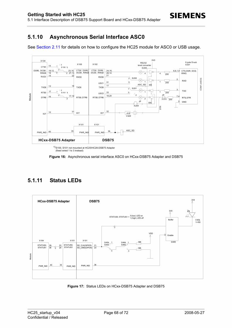
HC25_startup_v04 Page 68 of 72 2008-05-27Confidential / Released
Getting Started with HC255.1 Interface Description of DSB75 Support Board and HCxx-DSB75 Adapter71
s
5.1.10 Asynchronous Serial Interface ASC0
See Section 2.11 for details on how to configure the HC25 module for ASC0 or USB usage.
Figure 16: Asynchronous serial interface ASC0 on HCxx-DSB75 Adapter and DSB75
5.1.11 Status LEDs
Figure 17: Status LEDs on HCxx-DSB75 Adapter and DSB75
RXD0
TXD0
RTS0, DTR0
S200
S201
D200
IGT
PWR_IND
X102
1
3
1
3
200
200
200
200
4
1
2
4
1
1
CTS, DSR, DCD,RING
RXD
TXD
RTS, DTR
9 pole D-subX201
8,6,1,9
2
3
7,4
GND5
USC1
USC2
RS232level converter
V420
1
24,16,28,1421
31
17
33
18,20
36
32
3V0
d/dt
CO
M1
(AS
C0)
JP
X203
DT R
CTS0 , DSR0,DCD0 , RING0
ASC_SD
JP
X204EN
SD
ASC_SD
X101
RXD0
TXD0
RTS0, DTR0
IGT
PWR_IND
X100
CTS0 , DSR0,DCD0 , RING0
X101
TXD0
DTR0
IGT
PWR_IND
X104
DSR0 , DCD0 , RING0
S 100 1)3
12
CTS0
S 101 1)3
12
RTS0
RXD0
1)S100, S101 not mounted at HC25/HC28-DSB75 Adapter(fixed wired 1 to 3 instead)
23,15,27,13
22
18
17,19
31
35
18,12,1915
13
16
10
40
14
17
Mod
ule 2
3 2
2
DSB75HCxx-DSB75 Adapter
Buffer
Enable
S454,S455SD_CLK(GPIO5)
10KS464,S465
D450X101
PWR_IND
1
3
1
3
VDD
3V0
3V0
10K
V454,V 455
0 (low) LED on1 (high) LED offSTATUS0, STATUS1 =
21,23
36
X101
STATUS0,STATUS1
PWR_IND
X104
PWR_IND
22,24
3540
Mod
ule
39,38 2
2
2x
DSB75HCxx-DSB75 Adapter
SD_CMD(GPIO6)STATUS0,STATUS1

HC25_startup_v04 Page 69 of 72 2008-05-27Confidential / Released
Getting Started with HC255.1 Interface Description of DSB75 Support Board and HCxx-DSB75 Adapter71
s
5.1.12 Analog Audio Interface
The DSB75 Support Board and the HCxx-DSB75 Adapter have two analog audio interfaces,but the HC25 module has only one. Nevertheless you can connect audio devices to both audiointerfaces on the DSB75. To switch back and forth between both interfaces set the slideswitches S102 and S103 on the HCxx-DSB75 Adapter and select an appropriate audio modeusing the AT^SNFS command.
Audio interface 1 • Unbalanced audio interface optimized for the reference handset as part of the Siemens ref-
erence HC25 reference setup. Use the western jack X502 and set both slide switches S102and S103 to position 3 (marked MIC1 on the HCxx-DSB75 Adapter).
• Compatible audio equipment delivered with the DSB75 Support Board: "Votronic HandsetHH-SI-30"
Audio interface 2• Balanced audio interface designed for use with headsets or speakerphones. For this inter-
face the DSB75 Support Board provides the two 12-pin connectors named X700 or X701,each for a different connector size. For audio interface 2, set both slide switches S102 andS103 to position 2 (marked MIC2 on the HCxx-DSB75 Adapter).
• Compatible audio equipment that can be purchased for use with audio interface 2: - "Headset PTT HHS-510"- "Siemens Car Kit Portable HKP-500" compatible with Lumberg connector X701- "Siemens Car Kit Portable" compatible with Lumberg connector X700
Further details and a specification of both audio interfaces located on the DSB75 can be foundin [16].

HC25_startup_v04 Page 70 of 72 2008-05-27Confidential / Released
Getting Started with HC255.1 Interface Description of DSB75 Support Board and HCxx-DSB75 Adapter71
s
Figure 18: Audio interfaces on HCxx-DSB75 Adapter and DSB75
MICP1,MICN1
X101
VMIC_I
AGND_I
EPP
MICP
X 502
Western Jack
EPP1,EPN1
S716, 717 1
32
S712, 713 1
32
5V0
MICN2
VMIC_I
AGND_IEPP
EPP
MICP
MICP
X 700
X701
Lumberg
Lumberg
EPP2,EPN2
S710, 711 1
32
AGND_I
AGND_I
AGND
AGND
EPN
EPN
MICN
EPN
S731 1
3
S730 1
3VMIC
AGND
AGND_I
VMIC_I
FeedingBridge
FeedingBridge
34
12
38,36
6,4
2
8,10
6R8
6R8
6R8
6R8
4
1
3
2
10
12
9
11
11
10
12
8
>= 8 Ohm
32 Ohm
32 Ohm
Handset
Headset
Headset
Audio Interface 1:
Audio Interface 2:
MICP1_I,MICN1_I
or
+
+
+
MICP2
S 714 1
340
MICP2_I
X102
X101
X102
X101
MICP1,MICN1
X101
EPP,EPN
MICN2
EPP,EPN
VMIC
AGND
MICP2
X100
X101
X100
X101
33
11
37,35
5,3
1
7,9
39
S102,1032
31
1
6
2,3
4,5EPP,EPN
MICP,MICN
AGND
VMIC
S715 1
3
MICN2_I
100n
100n
100n
2
2
2
2
DSB75
Mod
ule
HCxx-DSB75 Adapter

HC25_startup_v04 Page 71 of 72 2008-05-27Confidential / Released
Getting Started with HC255.1 Interface Description of DSB75 Support Board and HCxx-DSB75 Adapter71
s
5.1.13 Power Supply Interface
Figure 19: Power supply interface on HCxx-DSB75 Adapter and DSB75
3V3_4V5
DC
DC
5.0V
Battery
+
-
red
black
X400
X401
X602
adj.
regulator
S601
3
1
PWR_IND
BATT+
4,5
3
1,2
X102
36
2,4,6,8,10
PSU9V...15V
X405
PWR_IND
N400
N410
LDO
N411
LDO
N412
PWR_IND
EN
VDD (2.9V)
3V0
V200
5V0
SD
15VDDLP 100µF+
GND1,3,5,7,9
VEXT12
PWR_IND
BATT+
X100
VDDLP
GND
VEXT
35
1,3,5,7,9
16
2,4,6,8,10
11
GND33,39,40
GND34,40,39
X101
X100
PWR_IND
BATT+
VDDLP
GND
VEXT
X104
21-25
33
26-30,
40
41
Mod
ule
DSB75HCxx-DSB75 Adapter

Getting Started with HC256 Index72
HC25_startup_v04 Page 72 of 72 2008-05-27Confidential / Released
s
6 Index
AAdapter board for DSB75 ......... 11, 13, 63Antenna .................................................. 11
Hirose U.FL ................................. 9, 11SMA .................................................. 11
APN .......................................... 46, 48, 50Application interface ................. 25, 39– 43ASC0 interface ........... 36, 37, 39, 42, 43AT Command Interpreter ........................ 39ATD ........................................................ 47ATE ........................................................ 53AT+CGATT ............................................ 46AT+CGDCONT ...................................... 46AT+CHUP .............................................. 47AT+CLCK ............................................... 50AT+COPS .............................................. 45AT+CPIN ......................................... 44, 50AT^SMSO .............................................. 44AT^SQPORT ................................... 39, 40AT^SUSB ............................................... 36Audio interface ....................................... 69
DDial-up network connection
Configuring ....................................... 54Using ................................................ 48
DSB75 Support Board .............. 11, 60, 63
GGPS antenna ..................................... 9, 11
HHSDPA/GPRS data transfer
Dial-up network connection 48, 52, 53Siemens Connection Manager ......... 48
IInstallation
Hardware ................................... 11, 60Update ................................ 32, 33, 34Windows Vista ........................... 19, 22Windows XP .............................. 14, 16
LLocal echo ....................................... 41, 53
MMass storage .............. 10, 14, 19, 23, 34Modem for ASC0 .................................... 37
Modem interface ....................... 24, 39– 43Mounting
Exploded view .................................. 63Instructions ....................................... 11
Multiplex mode .................. 40, 41, 42, 43
PPDP context ............................. 24, 46, 52
RRemovable disk ................. 14, 19, 23, 34RF antenna connector ....................... 9, 11
SSelecting access technology .................. 45Siemens Connection Manager .............................................................. 15– 28, 48– 51Siemens HSDPA USB Com Port ... 16, 24,
40Siemens HSDPA USB Modem .............................................................. 16, 24, 40, 48Siemens Wireless Ethernet Adapter 16, 25,
.......................................................... 48SMARTEQ MiniMag antenna ................... 9
TTechnical requirements ............................ 9
UUICC .................................................. 9, 39Uninstalling ...................................... 26– 30Unsolicited Result Codes ................ 39, 43Updating driver package ................. 32– 35
WWindows Device Manager ........ 24, 25, 31