user's guide: network management card. -...
TRANSCRIPT

®
USE
R’S
GU
IDE
Net
work
Man
agem
ent
Car
dContents
Introduction--1
Product Description . . . . . . . . . . . . . . . . . . . . . . . . . . . . . . . . . . 1Internal Management Features. . . . . . . . . . . . . . . . . . . . . . . . . . . 4Network Management Card Components . . . . . . . . . . . . . . . . . . . 6Watchdog Features . . . . . . . . . . . . . . . . . . . . . . . . . . . . . . . . . . 9
Control Console--10
How To Log On . . . . . . . . . . . . . . . . . . . . . . . . . . . . . . . . . . . . 10How to Recover from a Lost Password. . . . . . . . . . . . . . . . . . . . . 13Main Screen. . . . . . . . . . . . . . . . . . . . . . . . . . . . . . . . . . . . . . . 15Control Console Menus . . . . . . . . . . . . . . . . . . . . . . . . . . . . . . . 19
Web Interface--23
Introduction . . . . . . . . . . . . . . . . . . . . . . . . . . . . . . . . . . . . . . 23How to Log On . . . . . . . . . . . . . . . . . . . . . . . . . . . . . . . . . . . . 25Summary Page . . . . . . . . . . . . . . . . . . . . . . . . . . . . . . . . . . . . . 27Navigation Menu . . . . . . . . . . . . . . . . . . . . . . . . . . . . . . . . . . . 30
Network Menu--34
Introduction . . . . . . . . . . . . . . . . . . . . . . . . . . . . . . . . . . . . . . 34Option Settings . . . . . . . . . . . . . . . . . . . . . . . . . . . . . . . . . . . . 36
System Menu--62
Introduction . . . . . . . . . . . . . . . . . . . . . . . . . . . . . . . . . . . . . . 62Option Settings . . . . . . . . . . . . . . . . . . . . . . . . . . . . . . . . . . . . 64
Uninterruptible Power Supply Menu--71
Introduction . . . . . . . . . . . . . . . . . . . . . . . . . . . . . . . . . . . . . . 71Uninterruptible Power Supply Status . . . . . . . . . . . . . . . . . . . . . . 72Diagnostics . . . . . . . . . . . . . . . . . . . . . . . . . . . . . . . . . . . . . . . 77
i

®
USE
R’S
GU
IDE
Net
work
Man
agem
ent
Car
d
Control . . . . . . . . . . . . . . . . . . . . . . . . . . . . . . . . . . . . . . . . . . 80Configuration . . . . . . . . . . . . . . . . . . . . . . . . . . . . . . . . . . . . . 87PowerChute (PowerChute Network Shutdown) . . . . . . . . . . . . . . 90Scheduling Uninterruptible Power Supply Shutdown. . . . . . . . . . . 94Sync Control . . . . . . . . . . . . . . . . . . . . . . . . . . . . . . . . . . . . . . 99
Environment Menu--102
Introduction . . . . . . . . . . . . . . . . . . . . . . . . . . . . . . . . . . . . . 102Status Options . . . . . . . . . . . . . . . . . . . . . . . . . . . . . . . . . . . . 103Settings Options. . . . . . . . . . . . . . . . . . . . . . . . . . . . . . . . . . . 105
Event-Related Menus--107
Introduction . . . . . . . . . . . . . . . . . . . . . . . . . . . . . . . . . . . . . 107Event Log . . . . . . . . . . . . . . . . . . . . . . . . . . . . . . . . . . . . . . . 109Event Actions (Web Interface Only) . . . . . . . . . . . . . . . . . . . . . 115Event Recipients. . . . . . . . . . . . . . . . . . . . . . . . . . . . . . . . . . . 118E-mail Feature . . . . . . . . . . . . . . . . . . . . . . . . . . . . . . . . . . . . 120How to Configure Individual Events . . . . . . . . . . . . . . . . . . . . . 126
Data Menu (Web Interface Only)--128
Log Option . . . . . . . . . . . . . . . . . . . . . . . . . . . . . . . . . . . . . . 128Configuration Option . . . . . . . . . . . . . . . . . . . . . . . . . . . . . . . 129
Boot Mode--130
Introduction . . . . . . . . . . . . . . . . . . . . . . . . . . . . . . . . . . . . . 130DHCP Configuration Settings . . . . . . . . . . . . . . . . . . . . . . . . . . 133
Security--139
Security Features . . . . . . . . . . . . . . . . . . . . . . . . . . . . . . . . . . 139Authentication . . . . . . . . . . . . . . . . . . . . . . . . . . . . . . . . . . . . 143Encryption. . . . . . . . . . . . . . . . . . . . . . . . . . . . . . . . . . . . . . . 146Creating and Installing Digital Certificates . . . . . . . . . . . . . . . . . 150Firewalls . . . . . . . . . . . . . . . . . . . . . . . . . . . . . . . . . . . . . . . . 157
ii

®
USE
R’S
GU
IDE
Net
work
Man
agem
ent
Car
d
Using the Security Wizard--158
Overview . . . . . . . . . . . . . . . . . . . . . . . . . . . . . . . . . . . . . . . 158Create a Root Certificate & Server Certificates. . . . . . . . . . . . . . . 161Create a Server Certificate and Signing Request . . . . . . . . . . . . . 166Create an SSH Host Key. . . . . . . . . . . . . . . . . . . . . . . . . . . . . . 170
Troubleshooting--172
Network Management Card. . . . . . . . . . . . . . . . . . . . . . . . . . . 172
How to Export Configuration Settings--175
Retrieving and Exporting the .ini file. . . . . . . . . . . . . . . . . . . . . 175The Upload Event and its Error Messages . . . . . . . . . . . . . . . . . 180Using the Device IP Configuration Wizard . . . . . . . . . . . . . . . . . 182
Device IP Configuration Wizard--183
Purpose and Requirements . . . . . . . . . . . . . . . . . . . . . . . . . . . 183Install the Wizard . . . . . . . . . . . . . . . . . . . . . . . . . . . . . . . . . . 184Use the Wizard . . . . . . . . . . . . . . . . . . . . . . . . . . . . . . . . . . . 185
File Transfers--188
Introduction . . . . . . . . . . . . . . . . . . . . . . . . . . . . . . . . . . . . . 188Upgrading Firmware. . . . . . . . . . . . . . . . . . . . . . . . . . . . . . . . 189Verifying Upgrades and Updates . . . . . . . . . . . . . . . . . . . . . . . 196
Index--197
iii
®
USE
R’S
GU
IDE
Netw
ork
Man
ag
em
en
t C
ard
Introduction
Product Description
Features
The Network Management Card is a Web-based management product that uses multiple, open standards such as Telnet, HTTP, HTTPS, Secure Sockets Layer (SSL), Transport Layer Security (TLS), Secure CoPy (SCP), and Simple Network Management Protocol (SNMP) to provide full management of supported devices.
The following is a list of some of the Network Management Card features:• Provides the ability to export a user configuration (.ini) file from a
configured Network Management Card to one or more unconfigured Network Management Cards without converting the file to a binary file.
• Generates system log (Syslog) messages.• Enables the use of a Dynamic Host Configuration Protocol (DHCP)
server to provide the network (TCP/IP) values of the Network Management Card.
• Provides data and event logs.• Provides uninterruptible power supply scheduling features.• Provides support for the PowerChute® Network Shutdown utility.• Limits SNMP traps and e-mail notifications based on the severity level
of the uninterruptible power supply or system events.• Provides a selection of security protocols for authentication and
encryption.• Provides an Integrated Environmental Monitor that includes a
temperature probe, input contacts, and an output relay.
1

®
USE
R’S
GU
IDE
Netw
ork
Man
ag
em
en
t C
ard
Initial setup
You must define three TCP/IP settings for the Network Management Card before it can operate on the network:
• IP address of the Network Management Card.• Subnet mask.• IP address of the default gateway.
Network management features
Following are some of the network management applications and utilities that can work with an IBM uninterruptible power supply that connects to the network through the Network Management Card:
• Network management applications:– PowerChute Network Shutdown provides unattended remote
graceful shutdown of computers that are connected to uninterruptible power supplies.
– InfraStruXure® Manager provides enterprise-level power management and device management for uninterruptible power supplies.
Attention!
Never use the loopback address (127.0.0.1) as the default gateway address for the Network Management Card. Doing so will disable the card and will require you to reset TCP/IP settings to their defaults using a local serial login.
For instructions about how to configure the TCP/IP settings, see the Uninterruptible Power Supply Quick Installation Guide, provided in printed form and on the documentation CD as a PDF file.
To use a DHCP server to configure the TCP/IP settings of the Network Management Card, see "Boot Mode" on page 130.
2

®
USE
R’S
GU
IDE
Netw
ork
Man
ag
em
en
t C
ard
– PowerChute Business Edition provides safe system shutdown and uninterruptible power supply management for workstations and servers operating in a small or medium business environment.
• Wizard utilities:– The Device IP Configuration Wizard discovers unconfigured
Network Management Cards and enables you to configure their basic TCP/IP settings over the network.
– The Security Wizard creates components needed for high security for the Network Management Card on the network when you are using Secure Sockets Layer (SSL) and related protocols and encryption routines.
• A Management Information Base (MIB) browser uses the Object Identifiers (OIDs) of a MIB to perform SNMP SETs and GETs on an uninterruptible power supply.
3

®
USE
R’S
GU
IDE
Netw
ork
Man
ag
em
en
t C
ard
Internal Management Features
Overview
The Network Management Card has two internal interfaces (control console and Web interface), which provide menus with options that enable you to manage the uninterruptible power supply and the Network Management Card. The Network Management Card’s SNMP interface also enables you to use an SNMP browser with the PowerNet® Management Information Base (MIB) to manage the uninterruptible power supply.
Access priority for logging on
Only one user at a time can log on to the Network Management Card to use its internal user interface features. The priority for access is as follows:
• Local access to the control console from a computer with a direct serial connection to the Network Management Card always has the highest priority.
• Telnet or Secure SHell (SSH) access to the control console from a remote computer has priority over Web access.
• Web access has the lowest priority.
For more information about the internal user interfaces of the Network Management Card, see "Control Console" on page 10 and "Web Interface" on page 23.
To use the MIB with an SNMP browser, see the PowerNet® SNMP Management Information Base (MIB) Reference Guide, which is provided on the Network Management Card CD.
4
®
USE
R’S
GU
IDE
Netw
ork
Man
ag
em
en
t C
ard
Types of user accounts
The Network Management Card has three levels of access (Administrator, Device Manager, and Read-Only User), all of which are protected by user name and password requirements:
• An Administrator can use all of the management menus available in the control console and the Web interface. The Administrator’s default user name and password are both apc.
• A Device Manager can use only the uninterruptible power supply menu and the Log option in the Events menu. The Device Manager’s default user name is device, and the default password is apc.
• A Read-Only User has the following restricted access:– Access through the Web interface only.– Access to the same menus as a Device Manager, but without the
capability to change configurations, control devices, delete data, or use FTP-related options. Links to configuration options are visible but disabled, and the event and data logs display no Delete button.
The Read-Only User’s default user name is readonly, and the default password is apc.
For information about how SNMP access to the Network Management Card is controlled, see "SNMP" on page 50.
To set the user name and password for the three account types, see "User Manager" on page 64.
NoteYou must use the Web interface to configure values for the Read-Only User.
5
®
USE
R’S
GU
IDE
Netw
ork
Man
ag
em
en
t C
ard
Network Management Card Components
Face-plate and summary of components
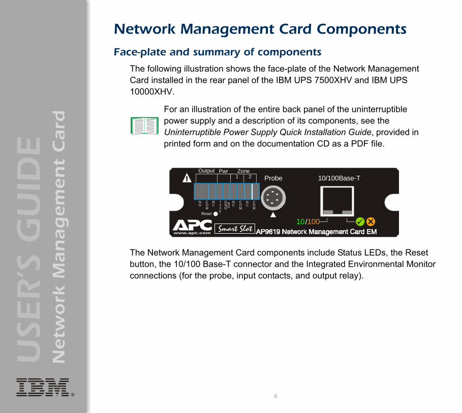
The following illustration shows the face-plate of the Network Management Card installed in the rear panel of the IBM UPS 7500XHV and IBM UPS 10000XHV.
The Network Management Card components include Status LEDs, the Reset button, the 10/100 Base-T connector and the Integrated Environmental Monitor connections (for the probe, input contacts, and output relay).
For an illustration of the entire back panel of the uninterruptible power supply and a description of its components, see the Uninterruptible Power Supply Quick Installation Guide, provided in printed form and on the documentation CD as a PDF file.
NO
10 100
+12V
COM
NC
NC
COM
COM
GND
/Reset
Smart Slot
Probe 10/100Base-TOutput Pwr Zone
1 2
NC
NO
6

®
USE
R’S
GU
IDE
Netw
ork
Man
ag
em
en
t C
ard
Features
Component Description
9-pin connector
• Output relay (Output): Normally closed (NC), common (COM), and normally open (NO) pins used by the output relay of the Integrated Environmental Monitor at the Network Management Card.
• Power (Pwr): Normally-open ground (GND NO) and +12VDC pins.• Input contacts (Zone 1 and 2): Two sets of normally closed (NC) and
common (COM) pins used by the Integrated Environmental Monitor at the Network Management Card.
Probe connector
Connects a Temperature/Humidity probe to the Integrated Environmental Monitor of the Network Management Card.
To manage the Integrated Environmental Monitor, see "Environment Menu" on page 102.
Reset button Resets the Network Management Card while power remains on.
10/100 Base-T connector
Connects the Network Management Card to the Ethernet network.
Status LEDs Located at the bottom right on the connector. See "Status LED" on page 8.
Link-RX/TX (10/100) LED
Located at the bottom left on the connector. See "Link-RX/TX (10/100) LED" on page 8.
7

®
USE
R’S
GU
IDE
Netw
ork
Man
ag
em
en
t C
ard
Link-RX/TX (10/100) LED
This LED indicates the network status.
Status LED
This LED indicates the status of the Network Management Card.
Condition Description
Off Either the Network Management Card is receiving no network traffic, or the device that connects the Network Management Card to the network is turned off or not operating correctly.
Flashing Green The Network Management Card is receiving data packets from the network at 10 Megabits per second (Mbps).
Flashing Orange The Network Management Card is receiving data packets from the network at 100 Megabits per second (Mbps).
Condition Description
Off The Network Management Card has no power.
Solid Green The Network Management Card has valid TCP/IP settings.
Flashing Green The Network Management Card does not have valid TCP/IP settings.1
Solid Orange A hardware failure has been detected in the Network Management Card. Contact IBM Customer Support.
Flashing Orange The Network Management Card is making BOOTP requests.
Flashing Orange and Green The Network Management Card is making DHCP2 requests.
1 If you do not use a BOOTP server, see the Uninterruptible Power Supply Quick Installation Guide provided in printed format and as a PDF file on the documentation CD to configure the TCP/IP settings of the Network Management Card.
2 To use a DHCP server, see "Boot Mode" on page 130.
8
®
USE
R’S
GU
IDE
Netw
ork
Man
ag
em
en
t C
ard
Watchdog Features
Overview
To detect internal problems and recover from unanticipated inputs, the Network Management Card uses internal, system-wide watchdog mechanisms. When it restarts to recover from an internal problem, a System: Warmstart event is recorded in the event log.
Network interface watchdog mechanism
The Network Management Card implements internal watchdog mechanisms to protect itself from becoming inaccessible over the network. For example, if the Network Management Card does not receive any network traffic for 9.5 minutes (either direct traffic, such as SNMP, or broadcast traffic, such as an Address Resolution Protocol [ARP] request), it assumes that there is a problem with its network interface and restarts.
Resetting the network timer
To ensure that the Network Management Card does not restart if the network is quiet for 9.5 minutes, the Network Management Card attempts to contact the Default Gateway every 4.5 minutes. If the gateway is present, it responds to the Network Management Card, and that response restarts the 9.5-minute timer. If your application does not require or have a gateway, specify the IP address of a computer that is running on the network most of the time and is on the same subnet. The network traffic of that computer will restart the 9.5-minute timer frequently enough to prevent the Network Management Card from restarting.
9

®
USE
R’S
GU
IDE
Netw
ork
Man
ag
em
en
t C
ard
Control Console
How To Log On
Overview
You can use either a local (serial) connection, or a remote (Telnet or SSH) connection with a computer on the same subnet as the Network Management Card to access the control console.
Use case-sensitive user name and password entries to log on (by default, apc and apc for an Administrator, or device and apc for a Device Manager). A Read-Only User has no access to the control console.
If you cannot remember your user name or password, see "How to Recover from a Lost Password" on page 13.
10

®
USE
R’S
GU
IDE
Netw
ork
Man
ag
em
en
t C
ard
Remote access to the control console
You can access the control console through Telnet or Secure SHell (SSH), depending on which is enabled. (An Administrator can enable these access methods through the Telnet/SSH option of the Network menu.) By default, Telnet is enabled. Enabling SSH automatically disables Telnet.
Telnet for basic access. Telnet provides the basic security of authentication by user name and password, but not the high-security benefits of encryption. To use Telnet to access the control console from any computer on the same subnet:
1. At a command prompt, type telnet and the System IP address for the Network Management Card (when the Network Management Card uses the default Telnet port of 23), and press Enter. For example: telnet 139.225.6.133
2. Enter the user name and password (by default, apc and apc for an Administrator, or device and apc for a Device Manager).
SSH for high-security access. If you use the high security of SSL for the Web interface, use Secure SHell (SSH) for access to the control console. SSH encrypts user names, passwords and transmitted data.
The interface, user accounts, and user access rights are the same whether you access the control console through SSH or Telnet, but to use SSH, you must first configure SSH and have an SSH client program installed on your computer.
Note
If the Network Management Card uses a non-default port number (between 5000 and 32767), you need to include a colon or a space (depending on your Telnet client) between the IP address and the port number.
11

®
USE
R’S
GU
IDE
Netw
ork
Man
ag
em
en
t C
ard
Local access to the control console
You can use a local computer that connects to the Network Management Card through the serial port at the uninterruptible power supply containing the Network Management Card to access the control console:
1. Select a serial port at the local computer and disable any service that uses that port.
2. Connect the smart-signaling cable that came with the uninterruptible power supply to the selected port and to the serial port of the uninterruptiple power supply.
3. Run a terminal program (such as HyperTerminal), and configure the selected port for 2400 bps, 8 data bits, no parity, 1 stop bit, and no flow control, and save the changes.
4. Press Enter to display the User Name prompt.5. Enter your user name and password.
12
®
USE
R’S
GU
IDE
Netw
ork
Man
ag
em
en
t C
ard
How to Recover from a Lost Password
You can use a local computer that connects to the Network Management Card through the serial port at the uninterruptible power supply to access the control console:1. Select a serial port at the local computer, and disable any service that uses that port.
2. Connect the smart-signaling cable that came with the uninterruptible power supply to the selected port and to the serial port of the uninterruptible power supply.
3. Run a terminal program (such as HyperTerminal) and configure the selected port as follows:– 2400 bps.– 8 data bits.– no parity.– 1 stop bit.– no flow control.
4. Press Enter, repeatedly if necessary, to display the User Name prompt. If you are unable to display the User Name prompt, verify the following:– The serial port is not in use by another application.– The terminal settings are correct as specified in step 3.– The correct cable is being used as specified in step 2.
5. Immediately press the Reset button. The Status LED will flash alternately orange and green. Press the Reset button a second time while the LED is flashing to reset the user name and password to the defaults temporarily.
6. Press Enter as many times as necessary to redisplay the User Name prompt, then use the default, apc, for the user name and password. (If
13
®
USE
R’S
GU
IDE
Netw
ork
Man
ag
em
en
t C
ard
you take longer than 30 seconds to log on after the User Name prompt is redisplayed, you must repeat step 5 and log on again.)
7. From the Control Console menu, select System, then User Manager.
8. Select Administrator, and change the user name and password settings, both of which are now defined as apc.
9. Press Ctrl+C, log off, reconnect any serial cable you disconnected, and restart any service you disabled.
14

®
USE
R’S
GU
IDE
Netw
ork
Man
ag
em
en
t C
ard
Main Screen
Example main screen
The following is an example of the screen that appears when you log on to the control console at the Network Management Card.
American Power Conversion Network Management Card AOS v2.5.3<c> Copyright 2004 All Rights Reserved Smart-UPS & Matrix-UPS APP v2.5.3-----------------------------------------------------------------------------Name : Test Lab Date : 06/15/2004Contact : Don Adams Time : 05:58:30Location : Building 3 User : AdministratorUp Time : 0 Days, 21 Hours, 21 Minutes Stat : P+ N+ A+
Thresholds OK, Contact Alarms OK, Relays OKIBM UPS 10000XHV named Tester 8 : On Line, No Alarms Present
------- Control Console -----------------------------------------------------
1- Device Manager 2- Network 3- System 4- Logout
<ESC>- Main Menu, <ENTER>- Refresh, <CTRL-L>- Event Log>
15

®
USE
R’S
GU
IDE
Netw
ork
Man
ag
em
en
t C
ard
Information and status fields
Main screen information fields.
• Two fields identify the operating system (AOS) and application (APP) firmware versions.Network Management Card AOS v2.5.3APP v2.5.3
• Three fields identify the system Name, Contact, and Location values.Name : Test LabContact : Don AdamsLocation : Building 3
• An Up Time field reports how long the Network Management Card has been running since it was last turned on or reset.Up Time : 0 Days 21 Hours 21 Minutes
• Two fields identify when you logged in, by Date and Time.Date : 06/15/2004Time : 5:58:20
• A User field identifies whether you logged in as Administrator or Device Manager. (The Read-Only User account cannot access the Control Console.)User : Administrator
For information about how to set the Name, Contact, and Location values, see "Identification" on page 65.
16

®
USE
R’S
GU
IDE
Netw
ork
Man
ag
em
en
t C
ard
Main screen status fields.
• A Stat field reports the Network Management Card status.Stat : P+ N+ A+
• A UPS model and name field reports the status of the uninterruptible power supply.IBM UPS 10000XHV named Tester 8 : On Line, No Alarms Present
P+ The operating system (AOS) is functioning properly.
N+ The network is functioning properly.
N? A BOOTP request cycle is in progress.
N– The Network Management Card failed to connect to the network.
N! Another device is using the IP address of the Network Management Card.
A+ The application is functioning properly.
A– The application has a bad checksum.
A? The application is initializing.
A! The application is not compatible with the AOS.
Note
The AOS should always report that it is functioning properly (P+). If the AOS is not functioning properly, and you cannot access the Network Management Card, contact IBM® Customer Support.
For more information about the status of the uninterruptible power supply, see "Uninterruptible Power Supply Status" on page 72.
17

®
USE
R’S
GU
IDE
Netw
ork
Man
ag
em
en
t C
ard
• Above the uninterruptible power supply status field (UPS model and name), three fields report the status of components of the Integrated Environmental Monitor. The Thresholds field reports status of the temperature probe, the Contact Alarms field reports the status of the contacts, and the Relay field reports the status of the output relay. For example:
Thresholds OK, Contact Alarms OK, Relay OK
For more information about the status of the uninterruptible power supply, see "Uninterruptible Power Supply Status" on page 72; for more information about probe, contact, and output relay status, see "Environment Menu" on page 102.
18

®
USE
R’S
GU
IDE
Netw
ork
Man
ag
em
en
t C
ard
Control Console Menus
Overview
The control console provides options to manage the Network Management Card (including the Integrated Environmental Monitor) and its uninterruptible power supply.
Main menu
The main Control Console menu has options that provide access to the management features of the control console:
1- Device Manager2- Network3- System4- Logout
Menu structure
The menus in the control console list options by number and name. To use an option, type the number of the option and press Enter, then follow any on-screen instructions.
Options that enable you to change a setting have an Accept Changes option that you must use before you exit a menu to save the changes you made.
NoteWhen you log on as Device Manager, you can access only the Device Manager menus and the Logout menu.
19

®
USE
R’S
GU
IDE
Netw
ork
Man
ag
em
en
t C
ard
While in a menu, you can also do the following:• Type ? and press Enter, to access brief menu option descriptions (if the
menu has help available).• Press Enter, to refresh the menu.• Press Esc, to go back to the menu from which you accessed the
current menu.• Press Ctrl+C, to return to the main (Control Console) menu.• Press Ctrl+D, to toggle between the uninterruptible power supply and
the Environment menus.• Press Ctrl+L, to access the event log.
For information about the event log, see "Event-Related Menus" on page 107.
20

®
USE
R’S
GU
IDE
Netw
ork
Man
ag
em
en
t C
ard
Device Manager optionThis option accesses the Device Manager menu. The options on this menu enable you to select the device that you want to manage.
1- IBM UPS 7500XHV or IBM UPS 10000XHV2- Environment
The Environment option accesses menu options used to configure the Integrated Environmental Monitor of the Network Management Card.T
Network optionTo do any of the following tasks, see "Network Menu" on page 34:
• Configure the TCP/IP settings of the Network Management Card, or, if the Network Management Card will obtain its TCP/IP settings from a server, configure the settings for the type of server (DHCP or BOOTP) to be used.
• Use the Ping utility.• Define settings that affect the FTP, Telnet, Web interface and SSL,
SNMP, e-mail, DNS, Syslog, and WAP (Wireless Application Protocol) features of the Network Management Card.
For information about the menu options that are available for managing the uninterruptible power supply, see "Uninterruptible Power Supply Menu" on page 71. For information about the menu options that are available for managing the Integrated Environmental Monitor, see "Environment Menu" on page 102.
21
®
USE
R’S
GU
IDE
Netw
ork
Man
ag
em
en
t C
ard
System optionTo do any of the following tasks, see "System Menu" on page 62:
• Control Administrator and Device Manager access. (You can control Read-Only User access by using the Web interface only.)
• Define system values for the Name, Contact, and Location fields.• Set the date and time used by the Network Management Card.• Through the Tools menu:
– Restart the Network Management Card.– Reset parameters to their default values.– Delete SSH host keys and SSL certificates.
• Access system information about the Network Management Card.
22
®
USE
R’S
GU
IDE
Netw
ork
Man
ag
em
en
t C
ard
Web Interface
Introduction
Overview
The Web interface provides options that you use to manage the Network Management Card (including its Integrated Environmental Monitor) and the uninterruptible power supply.
See "Web/SSL" on page 55 for information on the menu options you can use to select, enable, and disable the protocols that control access to the Web interface and to define the Web-server ports for the protocols.
23

®
USE
R’S
GU
IDE
Netw
ork
Man
ag
em
en
t C
ard
Supported Web Browsers
You can use Microsoft® Internet Explorer (IE) 5.0 (or later) or Netscape 4.0.8 (or later, except Netscape 6.x) to access the Network Management Card through its Web interface. Other commonly available browsers also might work but have not been fully tested.
Data verification, the event log, the data log, and Message Digest 5 (MD5) authentication require that you enable the following for your Web browser:
• JavaScript• Java®
• Cookies
In addition, the Network Management Card cannot work with a proxy server. Therefore, before you can use a Web browser to access its Web interface, you must do one of the following:
• Configure the Web browser to disable the use of a proxy server for the Network Management Card.
• Configure the proxy server so that it does not proxy the specific IP address of the Network Management Card.
24
®
USE
R’S
GU
IDE
Netw
ork
Man
ag
em
en
t C
ard
How to Log On
Overview
You can use the DNS name or System IP address of the Network Management Card for the URL address of the Web interface. Use your case-sensitive user name and password to log on. The default user name differs by account type:
• apc for an Administrator.• device for a Device Manager.• readonly for a Read-Only User.
The default password is apc for all three account types.
If you are using HTTPS (SSL/TSL) as your access protocol, your login credentials are compared with information in a server certificate. If the certificate was created with the Security Wizard:
• You must use an IP address to log on to the Network Management Card if an IP address was specified as the common name in the certificate.
• You must use a DNS name to log on if a DNS name was specified as the common name in the certificate.
For information about the Web page that is displayed when you log on to the Web interface, see "Summary Page" on page 27.
25
®
USE
R’S
GU
IDE
Netw
ork
Man
ag
em
en
t C
ard
26
URL address formats
Type the DNS name or IP address of the Network Management Card in the URL address field of the Web browser, and press Enter. Except when you specify a non-default Web server port in Internet Explorer, http:// or https:// is automatically added by the browser.
• For a DNS name of Web1, the entry would be one of the following:– http://Web1 if HTTP is your access mode.– https://Web1 if HTTPS (SSL/TLS) is your access mode.
• For a System IP address of 139.225.6.133, when the Network Management Card uses the default port (80) at the Web server, the entry would be one of the following:– http://139.225.6.133 if HTTP is your access mode.– https://139.225.6.133 if HTTPS (SSL/TLS) is your access
mode.• For a System IP address of 139.225.6.133, when the Network
Management Card uses a non-default port (5000, in this example) at the Web server, the entry would be one of the following:– http://139.225.6.133:5000 if HTTP is your access mode.– https://139.225.6.133:5000 if HTTPS (SSL/TLS) is your
access mode.
Note
If the error message You are not authorized to view this page is displayed (Internet Explorer only), another user is logged onto the Web interface or control console. If the error message No Response (Netscape) or This page cannot be displayed (Internet Explorer) is displayed, Web access might be disabled, or the Network Management Card might use a non-default Web-server port that you did not specify correctly in the address. (For Internet Explorer, you must type http:// as part of the address when any port other than 80 is used.)

®
USE
R’S
GU
IDE
Netw
ork
Man
ag
em
en
t C
ard
Summary Page
Example Web page
A navigation menu (see "Navigation Menu" on page 30) and summary page are displayed when you log on to the Web interface of the Network Management Card of an IBM UPS 7500XHV or IBM UPS 10000XHV model.
After the Network Management Card connects with an uninterruptible power supply, you can click the battery status icon on any Web interface page to access the summary page.
For more information about the help and status icons in the Web interface pages, see "Quick status tab" on page 29.
27

®
USE
R’S
GU
IDE
Netw
ork
Man
ag
em
en
t C
ard
Summary page fields
The summary page has two sections:• The uninterruptible power supply section reports the status of a
connected uninterruptible power supply.• The Network Management Card section reports the following
information:– The name, contact, and location information for the Network
Management Card.– The login date and time.– Type of user (Administrator, Device Manager, or Read-Only User).– How long (Up Time) the Network Management Card has been
continuously running since it was turned on or reset.– The status of the Network Management Card.
28

®
USE
R’S
GU
IDE
Netw
ork
Man
ag
em
en
t C
ard
Quick status tab
The quick status tab in the upper-right corner of every Web interface page can display two icons:
• A question mark (?) provides access to the online help for that page:
• A battery icon identifies the current status of the uninterruptible power supply and accesses the summary page from any other page:
• For the Integrated Environmental Monitor of the Network Management Card, icons identify any fault conditions:
The uninterruptible power supply is switched to bypass mode.
The uninterruptible power supply is operating normally.
The uninterruptible power supply is turned off.
The uninterruptible power supply is overloaded.
The uninterruptible power supply has a bad battery.
The uninterruptible power supply is switched to battery operation.
A fault exists at the uninterruptible power supply.
Communication with the uninterruptible power supply has been lost, or the uninterruptible power supply is unsupported.
A high-temperature threshold violation exists.
A low-temperature threshold violation exists.
States which contact device has a fault: either an input contact or the output relay at the Integrated Environmental Monitor.
29

®
USE
R’S
GU
IDE
Netw
ork
Man
ag
em
en
t C
ard
Navigation Menu
Overview
When you log on to the Web interface as an Administrator, the navigation menu (left frame) contains the following elements:
• The IP address of the Network Management Card.• The uninterruptible power supply menu which uses the uninterruptible
power supply model for its name (IBM UPS 10000XHV in the example on "Example Web page" on page 27).
• The Environment menu.• The Events menu.• The Data menu.• The Network menu.• The System menu.
• The Logout option.• The Help menu.• The Links menu.
Note
When you log on as a Device Manager or Read-Only User, the Network and System menus are not displayed in the navigation menu. Options are not available for the Read-Only User to make any changes.
30

®
USE
R’S
GU
IDE
Netw
ork
Man
ag
em
en
t C
ard
Selecting a menu to perform a task
Use the menus to perform tasks as follows:• To manage an uninterruptible power supply, and to set up and manage
Synchronized Control Groups, see "Uninterruptible Power Supply Menu" on page 71.
• To manage the Integrated Environmental Monitor of the Network Management Card, see "Environment Menu" on page 102.
• To do the following, see "Event-Related Menus" on page 107:– Access the event log.– Configure the actions to be taken based on the severity level of an
event.– Configure SNMP Trap Receiver settings to send event-based traps.– Define who will receive e-mail notifications of events.
• To do the following, see "Data Menu (Web Interface Only)" on page 128:– Access the data log.– Define the log interval (how often data will be sampled and
recorded) for the data log.• To do the following, see "Network Menu" on page 34:
– Configure new TCP/IP settings for the Network Management Card.– Identify the Domain Name System (DNS) server, test its network
connection, and enable or disable DNS Reverse Lookup Event Logging (which logs the domain name of the device associated with each event).
– Define settings for FTP, Telnet, SSH, the Web interface, SNMP, e-mail, and SSL/TLS.
– Configure the Syslog message feature of the Network Management Card.
– Enable or disable access to the Network Management Card by users of the Wireless Application Protocol (WAP).
31

®
USE
R’S
GU
IDE
Netw
ork
Man
ag
em
en
t C
ard
32
• To do the following, see "System Menu" on page 62:– Control Administrator, Device Manager, and Read-Only User access.– Define the system name, contact, and location.– Set the date and time used by the Network Management Card.– Through the Tools menu:
• Restart the user interface of the Network Management Card.• Reset parameters to their default values.• Delete SSH host keys and SSL certificates• Upload an initialization file (.ini file) that has been downloaded
from another Network Management Card. The current Network Management Card then uses the values in that .ini file to configure its own settings.
– Select Fahrenheit or Celsius for temperature displays.– Define the URL addresses used by the user links and logo link of the
Web interface, as described in "Links menu" on page 33.
Help menu
When you click Help, the contents page for the online help is displayed to provide for easy navigation to a specific online help topic. However, from any of the Web interface pages, you can use the question mark (?) in the quick status bar to link to the section of the online help for the content of that page.
Use the About System option of the Help menu to view information about the Network Management Card model number, serial number, hardware revision, date of manufacture, MAC address, application module and AOS module, including the date and time these modules were created.
For help on the type of flash memory used, see Flash Type in the About System option of the System menu in the control console.
®
USE
R’S
GU
IDE
Netw
ork
Man
ag
em
en
t C
ard
Links menu
This menu provides three user-definable URL link options. By default, these links access the following Web pages:
• APC’s Web Site accesses the APC home page.• Testdrive Demo accesses a demonstration page where you can use
samples of APC web-enabled products.• APC Monitoring option is not used with the IBM UPS 7500XHV and
IBM UPS 10000XHV models.
You can use the following procedure to redefine these links so that they point to other URLs:
1. Click on Links in the System menu.2. Define any new names for the user links.3. Define any new valid URL addresses that you want the user links to
access.4. Click Apply.
33

®
USE
R’S
GU
IDE
Netw
ork
Man
ag
em
en
t C
ard
Network Menu
Introduction
Overview
The Network menu has the options that you use to do the following tasks:• Define TCP/IP settings, including DHCP or BOOTP server settings,
when one of those types of servers is used to provide the required TCP/IP values.
• Use the Ping utility.• Define and display settings that affect the Network Management Card
settings for DNS, FTP, Telnet, SSH, SNMP, E-mail, Syslog, the Web interface (SSL/TLS), and WAP.
Note Only an Administrator has access to the Network menu.
34
®
USE
R’S
GU
IDE
Netw
ork
Man
ag
em
en
t C
ard
Menu options
Unless noted, the following menu options are available in the control console and Web interface:
• "TCP/IP" on page 36.• "DNS" on page 39.• "Send DNS Query (Web interface)" on page 40.• "Ping utility (control console)" on page 41.• "FTP Server" on page 42.• "Telnet/SSH" on page 43.• "SNMP" on page 50.• "Email" on page 51.• "Syslog" on page 52.• "Web/SSL" on page 55.• "WAP" on page 61.
35

®
USE
R’S
GU
IDE
Netw
ork
Man
ag
em
en
t C
ard
Option Settings
TCP/IP
This option accesses the following settings:• A Boot Mode setting selects the method used to define the TCP/IP
values that the Network Management Card needs to operate on the network:– System IP: The IP address of the Network Management Card.– Subnet Mask: The subnet mask value.– Default Gateway: The IP address of the default gateway.
• Advanced Settings define the Network Management Card host and domain names, as well as Ethernet port speed, BOOTP, and DHCP settings used by the Network Management Card.
Current TCP/IP settings fields. The current values for System IP, Subnet Mask, and Default Gateway, and the Network Management Card MAC Address, Host Name, Domain Name, and Ethernet Port Speed values are displayed above the TCP/IP settings in the control console and the Web interface.
For information about the watchdog role of the default gateway, see "Resetting the network timer" on page 9.
36

®
USE
R’S
GU
IDE
Netw
ork
Man
ag
em
en
t C
ard
Boot mode setting. This setting selects which method will be used to define the TCP/IP settings of the Network Management Card whenever the Network Management Card turns on, resets, or restarts:
• Manual: Three settings (System IP, Subnet Mask, and Default Gateway) which are available only when Manual is used to define the needed TCP/IP settings.
• BOOTP only: A BOOTP server provides the TCP/IP settings.• DHCP only: A DHCP server provides the TCP/IP settings.• DHCP & BOOTP: The Network Management Card will attempt to get
its TCP/IP settings from a BOOTP server first, and then, if it cannot discover a BOOTP server, from a DHCP server.
Note
An After IP Assignment setting, by default, will switch Boot mode from its default DHCP & BOOTP setting to BOOTP only or DHCP only, depending on the type of server that supplied the TCP/IP settings to the Network Management Card.
For information about the After IP Assignment setting, and other settings that affect how the Network Management Card uses BOOTP and DHCP, see "Advanced settings" on page 38. For more information about how to use DHCP, see "Boot Mode" on page 130.
37

®
USE
R’S
GU
IDE
Netw
ork
Man
ag
em
en
t C
ard
Advanced settings. The boot mode affects which settings are available:• Two settings are available for all Boot mode selections to define the
Network Management Card Host Name and Domain Name values:– Host Name: When an Administrator configures a host name here
and a domain name in the Domain Name field, users can then enter a host name in any field in the Network Management Card interface (except e-mail addresses) that accepts a domain name as input.
– Domain Name: An Administrator needs to configure the domain name here only. In all other fields in the Network Management Card interface (except e-mail addresses) that accept domain names, the Network Management Card will add this domain name when only a host name is entered.
• A Port Speed setting is available for all Boot mode selections to define communication speed of the TCP/IP port (Auto-negotiate, by default).
NoteTo override the expansion of a specified host name by the addition of the domain name, do one of the following:
• To override the behavior in all instances, set the Domain Name field in Configure General Settings to its default somedomain.com or to 0.0.0.0.
• To override the behavior for a particular host name entry (for example, when defining a trap receiver), include a trailing period. The Network Management Card recognizes a host name with a trailing period (such as mySnmpServer.) as if it were a fully qualified domain name and therefore does not append the domain name.
38

®
USE
R’S
GU
IDE
Netw
ork
Man
ag
em
en
t C
ard
• Three settings are available for all Boot mode selections, except Manual, to identify the Network Management Card in BOOTP or DHCP communication:– Vendor Class: Uses APC, by default.– Client ID: Uses the Network Management Card MAC address, by
default.
– User Class: Uses the application firmware module type for the Network Management Card (SUMX, by default).
• Two settings are available if BOOTP only is the Boot mode selection:– Retry Then Fail: Defines how many times the Network
Management Card will attempt to discover a BOOTP server before it stops (4, by default).
– On Retry Failure: Defines what TCP/IP settings will be used by the Network Management Card when it fails to discover a BOOTP server (Use Prior Settings, by default).
DNS
Use the DNS option to define the IP addresses of the primary and secondary Domain Name System (DNS) servers used by the e-mail feature of the Network Management Card. The primary DNS server will always be tried first.
Attention!
If the Client ID is changed from the Network Management Card MAC address, the new value must be unique on the LAN. Otherwise, the DHCP or BOOTP server might act incorrectly.
For information about the Advanced settings (DHCP Cookie Is and Retry Then Stop) that directly affect how DHCP is used, see "Boot Mode" on page 130.
For more information, see "E-mail Feature" on page 120 and "DNS servers" on page 121.
39
®
USE
R’S
GU
IDE
Netw
ork
Man
ag
em
en
t C
ard
Send DNS Query (Web interface). Use this option, available only through the DNS menu in the Web interface, to send a DNS query that tests the setup of your DNS servers.
Use the following settings to define the parameters for the test DNS request; you view the result of the test DNS request in the Last Query Response field (which displays No last query or text describing the query result of the last test).
• Use the Query Type setting to select the method to use for the DNS query:– The URL name of the server (Host).– The IP address of the server (IP).– The fully qualified domain name (FQDN).– The Mail Exchange used by the server (MX).
• Use the Query Question field to identify the value to be used for the selected Query Type: – For Host, identify the URL.– For IP, identify the IP address.– For FQDN, identify the fully qualified domain name, formatted as myserver.mydomain.com.
– For MX, identify the Mail Exchange address.• Enable or disable Reverse DNS Lookup, which is disabled by default.
Enable this feature unless you have no DNS server configured or have poor network performance because of heavy network traffic. With Reverse DNS Lookup enabled, when a network-related event occurs, reverse DNS lookup logs in the event log both the IP address and the domain name for the networked device associated with the event. If no domain name entry exists for the device, only its IP address is logged with the event. Since domain names generally change much less frequently than IP addresses, enabling reverse DNS lookup can improve the ability to identify addresses of networked devices that are causing events to occur.
40
®
USE
R’S
GU
IDE
Netw
ork
Man
ag
em
en
t C
ard
Ping utility (control console)
Select this option, available only in the control console, to check the network connection of the Network Management Card by testing whether a defined IP address or domain name responds to the Ping network utility. By default, the default gateway IP address (see "TCP/IP" on page 36) is used. However, you can use the IP address or domain name of any device known to be running on the network.
41

®
USE
R’S
GU
IDE
Netw
ork
Man
ag
em
en
t C
ard
FTP Server
Use the Access setting to enable or disable the FTP server. The server is enabled by default.
Use the Port setting to identify the TCP/IP port that the FTP server uses for communications with the Network Management Card. The default Port setting is 21.
You can change the Port setting to any unused port from 5000 to 32768 to enhance the protection provided by User Name and Password settings. You must then use a colon (:) in the command line to specify the non-default port. For example, for a port number of 5000 and the Network Management Card IP address of 152.214.12.114, you would type this command:
ftp 152.214.12.114:5000
Note
FTP transfers files without using encryption. For higher security, use Secure CoPy (SCP) for file transfers. When you select and configure Secure SHell (SSH), SCP is enabled automatically. If you decide to use SCP for file transfer, be sure to disable the FTP server.
To configure SSH, see "Telnet/SSH" on page 43.
To access a text version of the Network Management Card event or data log, see "How to use FTP or SCP to retrieve log files" on page 112.
To use FTP to download configuration files:• See "File Transfer (control console only)" on page 68 if
the files are on an FTP server of your company or agency.• See "Firmware file transfer methods" on page 190 if you
are downloading files from the IBM Web site.
42
®
USE
R’S
GU
IDE
Netw
ork
Man
ag
em
en
t C
ard
Telnet/SSH
Use the Telnet/SSH option to perform the following tasks:• Enable or disable Telnet or the Secure SHell (SSH) protocol for remote
control console access:– While SSH is enabled, you cannot use Telnet to access the control
console.– Enabling SSH enables SCP automatically.
– Do not enable both versions of SSH unless you require that both be activated at the same time. (Security protocols use extensive processing power.)
• Configure the port settings for Telnet and SSH.• Select one or more data encryption algorithms for SSH version 1, SSH
version 2, or both.• In the Web interface, specify a host key file previously created with the
Security Wizard and load it to the Network Management Card.
Note When SSH is enabled and its port and encryption ciphers are configured, no further configuration is required to use SCP. (SCP uses the same configuration as SSH.)
Note
To use SSH, you must have an SSH client installed. Most Linux® and other UNIX® platforms include an SSH client as part of their installation, but Microsoft Windows® operating systems do not. SSH clients are available from various vendors.
43
®
USE
R’S
GU
IDE
Netw
ork
Man
ag
em
en
t C
ard
• Display the fingerprint of the SSH host key for SSH versions 1 and 2. Most SSH clients display the fingerprint at the start of a session. Compare the fingerprint displayed by the client to the fingerprint that you recorded from the Web interface or control console of the Network Management Card.
NoteFrom a command line interface, such as the command prompt on Windows operating systems, you can use FTP or Secure CoPy (SCP) to transfer the host key file. You must transfer the file to the /sec folder on the Network Management Card.
If you do not specify a host key file, the Network Management Card generates an RSA host key of 768 bits, instead of the 1024-bit RSA host key that the Wizard creates. The Network Management Card can take up to 5 minutes to create this host key, and SSH is not accessible during that time.
Note
If you are using SSH version 2, expect a noticeable delay when logging on to the control console of the Network Management Card. Although the delay is not long, it can be mistaken for a problem because there is no explanatory message.
44
®
USE
R’S
GU
IDE
Netw
ork
Man
ag
em
en
t C
ard
Option Description
Telnet/SSH Network Configuration
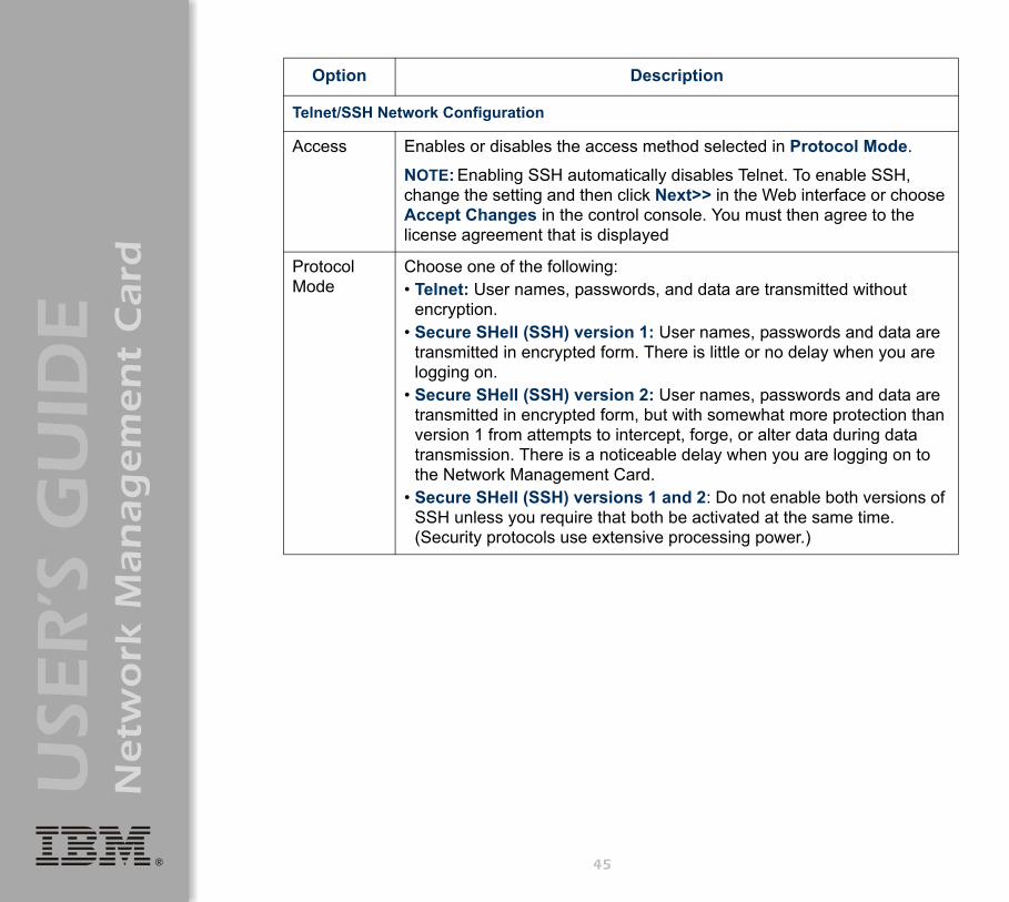
Access Enables or disables the access method selected in Protocol Mode.
NOTE: Enabling SSH automatically disables Telnet. To enable SSH, change the setting and then click Next>> in the Web interface or choose Accept Changes in the control console. You must then agree to the license agreement that is displayed
Protocol Mode
Choose one of the following: • Telnet: User names, passwords, and data are transmitted without
encryption. • Secure SHell (SSH) version 1: User names, passwords and data are
transmitted in encrypted form. There is little or no delay when you are logging on.
• Secure SHell (SSH) version 2: User names, passwords and data are transmitted in encrypted form, but with somewhat more protection than version 1 from attempts to intercept, forge, or alter data during data transmission. There is a noticeable delay when you are logging on to the Network Management Card.
• Secure SHell (SSH) versions 1 and 2: Do not enable both versions of SSH unless you require that both be activated at the same time. (Security protocols use extensive processing power.)
45
®
USE
R’S
GU
IDE
Netw
ork
Man
ag
em
en
t C
ard
Telnet/SSH Port Configuration
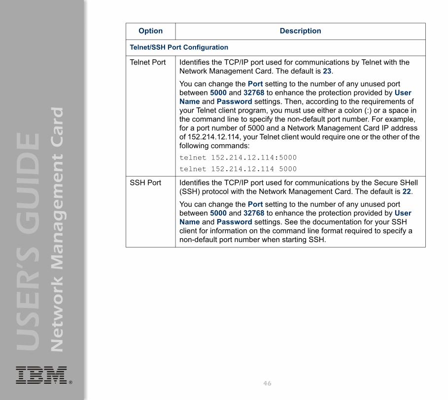
Telnet Port Identifies the TCP/IP port used for communications by Telnet with the Network Management Card. The default is 23.
You can change the Port setting to the number of any unused port between 5000 and 32768 to enhance the protection provided by User Name and Password settings. Then, according to the requirements of your Telnet client program, you must use either a colon (:) or a space in the command line to specify the non-default port number. For example, for a port number of 5000 and a Network Management Card IP address of 152.214.12.114, your Telnet client would require one or the other of the following commands:telnet 152.214.12.114:5000
telnet 152.214.12.114 5000
SSH Port Identifies the TCP/IP port used for communications by the Secure SHell (SSH) protocol with the Network Management Card. The default is 22.
You can change the Port setting to the number of any unused port between 5000 and 32768 to enhance the protection provided by User Name and Password settings. See the documentation for your SSH client for information on the command line format required to specify a non-default port number when starting SSH.
Option Description
46
®
USE
R’S
GU
IDE
Netw
ork
Man
ag
em
en
t C
ard
SSH Server Configuration
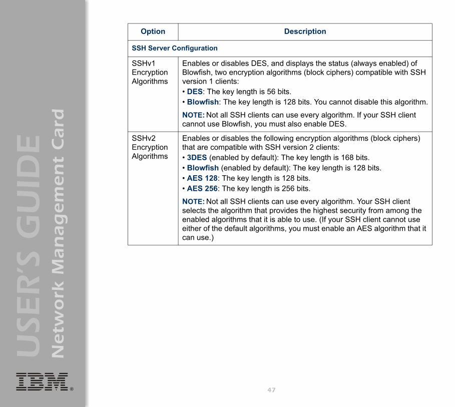
SSHv1 Encryption Algorithms
Enables or disables DES, and displays the status (always enabled) of Blowfish, two encryption algorithms (block ciphers) compatible with SSH version 1 clients:• DES: The key length is 56 bits.• Blowfish: The key length is 128 bits. You cannot disable this algorithm.
NOTE: Not all SSH clients can use every algorithm. If your SSH client cannot use Blowfish, you must also enable DES.
SSHv2 Encryption Algorithms
Enables or disables the following encryption algorithms (block ciphers) that are compatible with SSH version 2 clients:• 3DES (enabled by default): The key length is 168 bits.• Blowfish (enabled by default): The key length is 128 bits.• AES 128: The key length is 128 bits.• AES 256: The key length is 256 bits.
NOTE: Not all SSH clients can use every algorithm. Your SSH client selects the algorithm that provides the highest security from among the enabled algorithms that it is able to use. (If your SSH client cannot use either of the default algorithms, you must enable an AES algorithm that it can use.)
Option Description
47

®
USE
R’S
GU
IDE
Netw
ork
Man
ag
em
en
t C
ard
SSH User Host Key File
Status: The Status field Indicates the status of the host key (private key). In the control console, you display host key status by selecting Advanced SSH Configuration:• SSH Disabled: No host key in use: SSH currently is disabled and is
not using a host key. A host key may or may not be loaded.
NOTE: A host key must be installed to the /sec directory of the Network Management Card.
• Generating: The Network Management Card is generating a host key because no valid host key was installed in its /sec directory.
• Loading: A host key is being activated on the Network Management Card.
• Valid: The host key is valid. (If you install an invalid host key, the Network Management Card discards it and generates a valid one. However, a host key that the Network Management Card generates is only 768 bits in length. A valid host key created by the Security Wizard is 1024 bits.)
Filename: You can create a host key file with the Security Wizard and then upload it to the Network Management Card by using the Web interface. Use the Browse button for the Filename field to locate the file, then click Apply.
Alternatively, you can use FTP or Secure CoPy (SCP) to transfer the host key file to the Network Management Card.
NOTE: Creating and uploading a host key in advance reduces the time required to enable SSH. If no host key is loaded when you enable SSH, the Network Management Card creates one when it restarts. The Network Management Card takes up to 5 minutes to create this key, and the SSH server is not accessible during that time.
Option Description
48

®
USE
R’S
GU
IDE
Netw
ork
Man
ag
em
en
t C
ard
SSH Host Key Fingerprint
SSH v1: Displays the SSH version 1 fingerprint for the host key. The fingerprint is a unique identifier to further authenticate the host key. In the control console, choose Advanced SSH Configuration and then Host Key Information to display the fingerprint.
SSH v2: Displays the SSH version 2 fingerprint for the host key. The fingerprint is a unique identifier to further authenticate the host key. In the control console, choose Advanced SSH Configuration and then Host Key Information to display the fingerprint.
Option Description
49

®
USE
R’S
GU
IDE
Netw
ork
Man
ag
em
en
t C
ard
SNMP
An Access option (Settings in the control console) enables (by default) or disables SNMP. When SNMP is enabled, the Access Control settings enable you to control how each of the four available SNMP channels is used.
To define up to four Network Management Stations as trap receivers, see "Trap Receivers" on page 119.
Setting Definition
Community Name
This setting defines the password (maximum of 15 characters) which a Network Management Station (NMS) that is defined by the NMS IP/Domain Name setting uses to access the channel.
NMS IP/Domain Name
Limits access to the NMS specified by a domain name or to the NMSs specified by the format used for the IP address:
• A domain name allows only the NMS at that location to have access.• 159.215.12.1 allows only the NMS with that IP address to have access.• 159.215.12.255 allows access for any NMS on the 159.215.12 segment.• 159.215.255.255 allows access for any NMS on the 159.215 segment.• 159.255.255.255 allows access for any NMS on the 159 segment.• 0.0.0.0 or 255.255.255.255 allows access for any NMS.
Access Type
Selects how the NMS defined by the NMS IP/Domain Name setting can use the channel, when that NMS uses the correct value for Community Name.
Read The NMS can use GETs at any time, but it can never use SETs.
Write The NMS can use GETs at any time, and can use SETs when no one is logged on to the control console or Web interface.
Disabled The NMS cannot use GETs or SETs.
Write+ The NMS can use GETs and SETs at any time, even when someone is logged on to the control console or Web interface.
50

®
USE
R’S
GU
IDE
Netw
ork
Man
ag
em
en
t C
ard
You use this option to define two SMTP settings (SMTP Server and From Address) used by the e-mail feature of the Network Management Card.
For more information, see "SMTP settings" on page 122 and "E-mail Feature" on page 120.
51
®
USE
R’S
GU
IDE
Netw
ork
Man
ag
em
en
t C
ard
52
Syslog
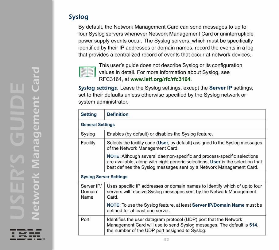
By default, the Network Management Card can send messages to up to four Syslog servers whenever Network Management Card or uninterruptible power supply events occur. The Syslog servers, which must be specifically identified by their IP addresses or domain names, record the events in a log that provides a centralized record of events that occur at network devices.
Syslog settings. Leave the Syslog settings, except the Server IP settings, set to their defaults unless otherwise specified by the Syslog network or system administrator.
This user’s guide does not describe Syslog or its configuration values in detail. For more information about Syslog, see RFC3164, at www.ietf.org/rfc/rfc3164.
Setting Definition
General Settings
Syslog Enables (by default) or disables the Syslog feature.
Facility Selects the facility code (User, by default) assigned to the Syslog messages of the Network Management Card.
NOTE: Although several daemon-specific and process-specific selections are available, along with eight generic selections, User is the selection that best defines the Syslog messages sent by a Network Management Card.
Syslog Server Settings
Server IP/Domain Name
Uses specific IP addresses or domain names to Identify which of up to four servers will receive Syslog messages sent by the Network Management Card.
NOTE: To use the Syslog feature, at least Server IP/Domain Name must be defined for at least one server.
Port Identifies the user datagram protocol (UDP) port that the Network Management Card will use to send Syslog messages. The default is 514, the number of the UDP port assigned to Syslog.

®
USE
R’S
GU
IDE
Netw
ork
Man
ag
em
en
t C
ard
Local Priority (Severity Mapping)
Map to Syslog’s Priorities
Maps each of the severity levels (Local Priority settings) that can be assigned to uninterruptible power supply and Network Management Card events to the available Syslog priorities. The following definitions are from RFC3164:• Emergency: The system is unusable.• Alert: Action must be taken immediately.• Critical: Critical conditions.• Error: Error conditions.• Warning: Warning conditions.• Notice: Normal but significant conditions.• Informational: Informational messages.• Debug: Debug-level messages.
Following are the default settings for the four Local Priority settings:• Severe is mapped to Critical.• Warning is mapped to Warning.• Informational is mapped to Info.• None (for events that have no severity level assigned) is mapped to Info.
NOTE: To disable sending Syslog messages for Severe, Warning, or Informational events, see "Event Actions (Web Interface Only)" on page 115.
Setting Definition
53

®
USE
R’S
GU
IDE
Netw
ork
Man
ag
em
en
t C
ard
Syslog test (Web interface). This option enables you to send a test message to the Syslog servers configured in the Syslog Server section:
1. Select the priority you want to assign to the test message.2. Define the test message, using any text that is formatted as described
in "Syslog message format" on this page. For example, APC: Test message, meets the required message format.
3. Click Apply to have the Network Management Card send a Syslog message that uses the defined Priority and Test Message settings.
Syslog message format. A Syslog message has three parts:• The priority (PRI) part identifies the Syslog priority assigned to the
event associated with the message and identifies the facility code assigned to messages sent by the Network Management Card.
• The Header includes a time stamp and the IP address of the Network Management Card.
• The message (MSG) part has two fields:– A TAG field, which is followed by a colon and a space, identifies the
event type.– A CONTENT field provides the event text, followed by a space and
the event code.
54

®
USE
R’S
GU
IDE
Netw
ork
Man
ag
em
en
t C
ard
Web/SSL
Use the Web/SSL menu to perform the following tasks:• Enable or disable the two protocols that provide access to the Web
interface of the Network Management Card:– Hypertext Transfer Protocol (HTTP) provides access by user name
and password, but does not encrypt user names, passwords, and data during transmission.
– Hypertext Transfer Protocol over Secure Sockets Layer (HTTPS). Secure Sockets Layer (SSL) encrypts user names, passwords, and data during transmission and provides authentication of the Network Management Card by means of digital certificates.
• Configure the ports that each of the two protocols will use.• Select the encryption ciphers that SSL will use.• Identify whether a server certificate is installed on the Network
Management Card. If a certificate has been created with the Security Wizard but is not installed:– In the Web interface, browse to the certificate file and upload it to the
Network Management Card.– Alternatively, use the Secure CoPy (SCP) protocol or FTP to upload
it to the /sec directory on the Network Management Card.
See"Creating and Installing Digital Certificates" on page 150 to choose among the several methods for using digital certificates.
55

®
USE
R’S
GU
IDE
Netw
ork
Man
ag
em
en
t C
ard
• Display the configured parameters of a digital server certificate, if one is installed.
NoteCreating and uploading a server certificate in advance reduces the time required to enable HTTPS (SSL/TLS). If no server certificate is loaded when you enable HTTPS (SSL/TLS), the Network Management Card creates one when it restarts. The Network Management Card can take up to 5 minutes to create this certificate, and the SSL/TLS server is not available during that time.
Option Description
Web/SSL Network Configuration
Access Enables or disables the access method selected in Protocol Mode.
Protocol Mode Choose one of the following: • HTTP: User names, passwords, and data are transmitted without
encryption.• HTTPS (SSL/TLS): User names, passwords and data are
transmitted in encrypted form, and digital certificates are used for authentication.
NOTE: To enable HTTPS (SSL/TLS), change the setting and then click Next>> in the Web interface, or choose Accept Changes in the control console. You must then agree to the license agreement that is displayed. To activate the changes you must log off and log back on to the interface. When SSL is activated, your browser displays a lock icon, usually at the bottom of the screen.
56
®
USE
R’S
GU
IDE
Netw
ork
Man
ag
em
en
t C
ard
HTTP/HTTPS Port Configuration
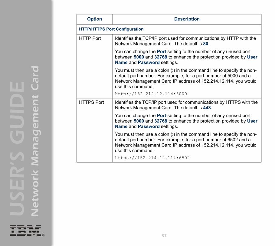
HTTP Port Identifies the TCP/IP port used for communications by HTTP with the Network Management Card. The default is 80.
You can change the Port setting to the number of any unused port between 5000 and 32768 to enhance the protection provided by User Name and Password settings.
You must then use a colon (:) in the command line to specify the non-default port number. For example, for a port number of 5000 and a Network Management Card IP address of 152.214.12.114, you would use this command:http://152.214.12.114:5000
HTTPS Port Identifies the TCP/IP port used for communications by HTTPS with the Network Management Card. The default is 443.
You can change the Port setting to the number of any unused port between 5000 and 32768 to enhance the protection provided by User Name and Password settings.
You must then use a colon (:) in the command line to specify the non-default port number. For example, for a port number of 6502 and a Network Management Card IP address of 152.214.12.114, you would use this command:https://152.214.12.114:6502
Option Description
57

®
USE
R’S
GU
IDE
Netw
ork
Man
ag
em
en
t C
ard
SSL Server Configuration
CipherSuite Enables or disables the following SSL encryption ciphers and hash algorithms. (To access these options in the control console, choose Web/SSL, then Advanced SSL/TLS Configuration.)
NOTE: All of these encryption ciphers and hash algorithms use the RSA public key algorithm.• DES (SSL_RSA_WITH_DES_CBC_SHA): a block cipher with a key
length of 56 bits. The Secure Hash Algorithm (SHA) is used for authentication.
• 3DES (SSL_RSA_WITH_3DES_EDE_CBC_SHA): a block cipher with a key length of 168 bits. A Secure Hash Algorithm (SHA) is used for authentication.
• RC4 (SSL_RSA_WITH_RC4_128_MD5): a stream cipher with a key length of 128 bits, with an RSA key exchange algorithm, and with a Message Digest 5 (MD5) hash algorithm used for authentication. This selection is enabled by default.
• RC4 (SSL_RSA_WITH_RC4_128_SHA): a stream cipher with a key length of 128 bits. A Secure Hash Algorithm (SHA) is used for authentication. This selection is enabled by default.
Option Description
58

®
USE
R’S
GU
IDE
Netw
ork
Man
ag
em
en
t C
ard
SSL/TLS Server Certificate
Status: The Status field indicates whether a server certificate is installed: (To display the status in the control console, choose Web/SSL/TLS, then Advanced SSL/TLS Configuration.)• Not installed: No certificate is installed on the Network Management
Card.
NOTE: If you install a certificate by using FTP or SCP, you must specify the correct directory (/sec) on the Network Management Card.
• Generating: The Network Management Card is generating a certificate because no valid certificate was installed.
• Loading: A certificate is being loaded (activated on the Network Management Card).
• Valid: A valid certificate was installed to or generated by the Network Management Card. (If you install an invalid certificate, the Network Management Card discards it and generates a valid one. However, a certificate that the Network Management Card generates has some limitations. See "Method 1: Use the auto-generated default certificate of the Network Management Card" on page 151.)
Filename: You can create a server certificate with the Security Wizard and then upload it to the Network Management Card by using the Web interface. Use the Browse button for the Filename field to locate the file, then click Apply. By default, the certificate is installed to the correct location.
Alternatively, you can use FTP or Secure CoPy (SCP) to transfer the server certificate to the Network Management Card. However, you must specify the correct location (/sec) on the Network Management Card.
NOTE: Creating and uploading a server certificate in advance reduces the time required to enable HTTPS (SSL/TLS). If no server certificate is loaded when you enable HTTPS (SSL/TLS), the Network Management Card creates one when it restarts. The Network Management Card can take up to 5 minutes to create this certificate, and the SSL/TLS server is not available during that time.
Option Description
59

®
USE
R’S
GU
IDE
Netw
ork
Man
ag
em
en
t C
ard
Parameter Description
Current Certificate Details
Issued to: Common Name (CN): The IP Address or DNS name of the Network Management Card, except if the server certificate was generated by default by the Network Management Card. For a default server certificate, the Common Name (CN) field displays the Network Management Card serial number.
NOTE: If an IP address was specified as the Common Name when the certificate was created, use an IP address to log on to the Web interface of the Network Management Card; if the DNS name was specified as the Common Name, use the DNS name to log on. When you log on, if you do not use the IP address or DNS name that was specified for the certificate, authentication fails, and you receive an error message asking if you want to continue.
Organization (O), Organizational Unit (OU), and Locality, Country: The name, organizational unit, and location of the organization that is using the server certificate. If the server certificate was generated by default by the Network Management Card, the Organizational Unit (OU) field displays “Internally Generated Certificate.”
Serial Number: The serial number of the server certificate.
Issued By: Common Name (CN): The Common Name as specified in the CA root certificate, except if the server certificate was generated by default by the Network Management Card. For a default server certificate, the Common Name (CN) field displays the Network Management Card serial number.
Organization (O) and Organizational Unit (OU): The name and organizational unit of the organization that issued the server certificate. If the server certificate was generated by default by the Network Management Card, the Organizational Unit (OU) field displays “Internally Generated Certificate.”
Validity Issued on: The date and time at which the certificate was issued.
Expires on: The date and time at which the certificate expires.
60

®
USE
R’S
GU
IDE
Netw
ork
Man
ag
em
en
t C
ard
WAP
Use this option to enable (the default) or disable the Wireless Application Protocol (WAP). WAP is a standard for providing cellular phones, pagers and other handheld devices with secure access to e-mail and text-based Web pages. WAP runs on all major wireless networks and is device- independent, so that it can be used with many phones and handheld devices.
Fingerprints Each of the two fingerprints is a long string of alphanumeric characters punctuated by colons. A fingerprint is a unique identifier that you can use to further authenticate the server. Record the fingerprints to compare with the fingerprints contained in the certificate, as displayed in the browser.
SHA1 Fingerprint: This fingerprint is created by a Secure Hash Algorithm (SHA).
MD5 Fingerprint: This fingerprint is created by a Message Digest 5 (MD5) algorithm.
Parameter Description
61
®
USE
R’S
GU
IDE
Netw
ork
Man
ag
em
en
t C
ard
System Menu
Introduction
Overview
Use the System menu to do the following tasks:• Configure system identification, date and time settings, and access
parameters for the Administrator, Device Manager, and Read-Only User accounts.
• Synchronize the Network Management Card real-time clock with a Network Time Protocol (NTP) server.
• Reset or restart the Network Management Card.• Define the URL links available in the Web interface.• Access hardware and firmware information about the Network
Management Card.• Set the units (Fahrenheit or Celsius) used for temperature displays.
Note Only an Administrator has access to the System menu.
62

®
USE
R’S
GU
IDE
Netw
ork
Man
ag
em
en
t C
ard
Menu options
Unless noted, the following menu options are available in the control console and Web interface:
• "User Manager" on page 64.• "Identification" on page 65.• "Date & Time" on page 65.• "Tools" on page 67.• "Preferences (Web interface)" on page 69.• "Links (Web interface)" on page 69.• "About System" on page 70.
Note About System is an option of the Help menu in the Web interface.
63

®
USE
R’S
GU
IDE
Netw
ork
Man
ag
em
en
t C
ard
Option Settings
User Manager
Use this option to define the access values shared by the control console and the Web interface, and the authentication used to access the Web interface.
Setting Definition
Values affecting all users
Auto Logout The number of minutes (3 by default) before a user is automatically logged off because of inactivity.
Authentication The Basic setting (default) causes the Web interface to use standard HTTP 1.1 login (base64-encoded passwords); MD5 causes the Web interface to use an MD5-based authentication login.
NOTE: Cookies must be enabled at a browser before it can be used with MD5 authentication.
Separate values for Administrator, Device Manager, and Read Only User
User Name The case-sensitive name (maximum of 10 characters) used by Administrator and Device Manager users to log on at the control console or Web interface and by the Read-Only User to log on at the Web interface. Default values are apc for Administrator users, device for Device Manager users, and readonly for the Read-Only User.
Password The case-sensitive password (maximum of 10 characters) always used to log on at the control console, but only used to log on to the Web interface when Basic is selected for the Authentication setting (apc is the default password for the three account types).
NOTE: A Read-Only User cannot log on through the control console.
Authentication Phrase
The case-sensitive, 15-to-32 character phrase used to log on to the Web interface when MD5 is the Authentication setting. Default settings are:• admin user phrase for Administrator• device user phrase for Device Manager • readonly user phrase for Read-Only User
64

®
USE
R’S
GU
IDE
Netw
ork
Man
ag
em
en
t C
ard
Identification
Use this option to define the System Name, Location, and Contact values used by the SNMP agent of the Network Management Card. The settings for this option provide the values used for the MIB-II sysName, sysContact, and sysLocation OIDs.
Date & Time
Use this option to set the time and date used by the Network Management Card. The option displays the current settings, and enables you to change those settings manually, or through a Network Time Protocol (NTP) Server.
Set Manually. Use this option in the Web interface, or Manual in the control console, to define the date and time for the Network Management Card.
For more information about the MIB-II OIDs, see the PowerNet® SNMP Management Information Base (MIB) Reference Guide provided on the Network Management Card CD.
Note
An Apply Local Computer Time to Network Management Card option, which is available in the Web interface only, sets these values to match the date and time settings of the computer you are using to access the Web interface.
65

®
USE
R’S
GU
IDE
Netw
ork
Man
ag
em
en
t C
ard
Synchronize with Network Time Protocol (NTP) Server. Use this option, or Network Time Protocol (NTP) in the control console, to have an NTP Server update the date and time for the Network Management Card automatically.
NoteIn the control console, use the NTP Client option to enable or disable (the default) the NTP Server updates. In the Web interface, use the Set Manually option to disable the updates.
Setting Definition
Primary NTP Server Identifies the IP address or domain name of the primary NTP server.
Secondary NTP Server
Identifies the IP address or domain name of the secondary NTP server, when a secondary server is available.
GMT Offset (Time Zone)
Defines the offset from Greenwich Mean Time (GMT) based on the time zone of the Network Management Card.
Update Interval Defines how often, in hours, the Network Management Card accesses the NTP Server for an update. The minimum is 1 hour; the maximum is 8760 hours (1 year). Use Update Using NTP Now to initiate an immediate update as well.
66

®
USE
R’S
GU
IDE
Netw
ork
Man
ag
em
en
t C
ard
Tools
Initiating an action. Use this drop-down list in the Web interface or the equivalent menu options in the control console to restart the interface of the Network Management Card, to reset some or all of its configuration settings to their default values, or to delete SSH Host Keys and SSL Certificates.
Action Definition
Reboot Management Interface
Restarts the interface of the Network Management Card.
Reset to Defaults Resets all configuration settings.
NOTE: For information about how this affects the Boot mode setting, see the description of Reset Only TCP/IP to Defaults in this table.
Reset to Defaults Except TCP/IP
Resets all configuration settings except the TCP/IP settings.
Reset Only TCP/IP to Defaults
Resets the TCP/IP settings only.
NOTE: WIth Boot mode set to DHCP & BOOTP, its default setting, the TCP/IP settings of the Network Management Card must be defined by a DHCP or BOOTP server. See "TCP/IP" on page 36.
Delete SSH Host Keys and SSL Certificates
Removes any SSH host key and server certificate on the Network Management Card so that you can reconfigure these components of your security system.
67

®
USE
R’S
GU
IDE
Netw
ork
Man
ag
em
en
t C
ard
Uploading an initialization file (Web interface only). To transfer configuration settings from a configured Network Management Card to the current Network Management Card, export the .ini file from the configured Network Management Card, select the Tools menu on the current Network Management Card, browse to the file, and click Upload. The current Network Management Card imports the file and uses it to set its own configuration. The Status field reports the progress of the upload.
File Transfer (control console only). The File Transfer option of the Tools menu provides two methods for file transfer over the network and one for file transfer through a serial connection to the Network Management Card.
See "How to Export Configuration Settings" on page 175 for information on the content of the .ini file, how to preserve comments you add to the file, and how to export settings to multiple Network Management Cards.
Option Description
XMODEM Enables you to transfer either an .ini file or a firmware upgrade file to a Network Management Card using a terminal-emulation program. This option is available only when you use a local connection to the control console. See "Local access to the control console" on page 12.
FTP Client
Use one of these two option to transfer either an .ini file or a firmware upgrade file from an FTP or TFTP server of your organization (company, agency, or department) to the current Network Management Card. These options assume that your organization has a centralized system for configuring or upgrading Network Management Cards.
For FTP Client, you are prompted for a user name and password. For either option, you are then prompted for the server address and the file to transfer. After you supply that required information, the Network Management Card transfers the file.
TFTP Client
68
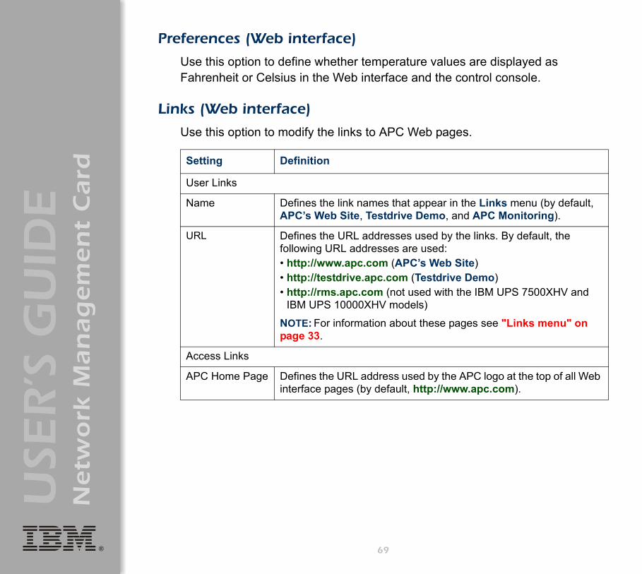
®
USE
R’S
GU
IDE
Netw
ork
Man
ag
em
en
t C
ard
Preferences (Web interface)
Use this option to define whether temperature values are displayed as Fahrenheit or Celsius in the Web interface and the control console.
Links (Web interface)
Use this option to modify the links to APC Web pages.
Setting Definition
User Links
Name Defines the link names that appear in the Links menu (by default, APC’s Web Site, Testdrive Demo, and APC Monitoring).
URL Defines the URL addresses used by the links. By default, the following URL addresses are used:• http://www.apc.com (APC’s Web Site)• http://testdrive.apc.com (Testdrive Demo)• http://rms.apc.com (not used with the IBM UPS 7500XHV and
IBM UPS 10000XHV models)
NOTE: For information about these pages see "Links menu" on page 33.
Access Links
APC Home Page Defines the URL address used by the APC logo at the top of all Web interface pages (by default, http://www.apc.com).
69
®
USE
R’S
GU
IDE
Netw
ork
Man
ag
em
en
t C
ard
About System
This option identifies hardware information for the Network Management Card, including model number, serial number, date of manufacture, hardware revision, MAC address, and flash type.
This information is set at the factory and cannot be changed.
NoteIn the Web interface, except for flash type, this hardware information is reported by the About System option in the Help menu.
70

®
USE
R’S
GU
IDE
Netw
ork
Man
ag
em
en
t C
ard
Uninterruptible Power Supply Menu
Introduction
71
Overview
In the Web interface, the uninterruptible power supply menu is in the navigation menu; in the control console, you access the uninterruptible power supply menu through the Device Manager option in the Control Console menu. The menu is named with the model name of the uninterruptible power supply you are using, such as IBM UPS 7500XHV.
Uninterruptible power supply menu options
The uninterruptible power supply menu options and the information they provide vary by uninterruptible power supply model.
For information about the uninterruptible power supply menu options available in both the control console and the Web interface, see the following:
• "Uninterruptible Power Supply Status" on page 72.• "Diagnostics" on page 77.• "Control" on page 80.• "Configuration" on page 87.• "PowerChute (PowerChute Network Shutdown)" on page 90.• "Scheduling Uninterruptible Power Supply Shutdown" on
page 94.• "Sync Control" on page 99.

®
USE
R’S
GU
IDE
Netw
ork
Man
ag
em
en
t C
ard
Uninterruptible Power Supply Status
Overview
The Status options provide access to the information described in the following sections:
• "Detailed uninterruptible power supply status" on page 73.• "Utility Power Status" on page 74.• "Output Power Status" on page 75.• "Battery Status" on page 76.
72
®
USE
R’S
GU
IDE
Netw
ork
Man
ag
em
en
t C
ard
Detailed uninterruptible power supply status
The uninterruptible power supply menu provides an option to display uninterruptible power supply status:
• In the Web interface, use the Status option.• In the control console, use the Detailed Status option.
.
The following information is displayed:• The current status of the uninterruptible power supply:
– Whether the uninterruptible power supply is online, and whether any alarms are present.
• The reason for the last transfer to battery power at the uninterruptible power supply.
• The internal temperature of the uninterruptible power supply.• The runtime that is available currently to the uninterruptible power supply.• The values described in "Utility Power Status" on page 74, "Output
Power Status" on page 75, and "Battery Status" on page 76.
NoteIn the control console, the Detailed Status option accesses expanded descriptions of the uninterruptible power supply status.
For a list of the uninterruptible power supply events that can be reported as part of the uninterruptible power supply status, see "Event List page" on page 126.
73
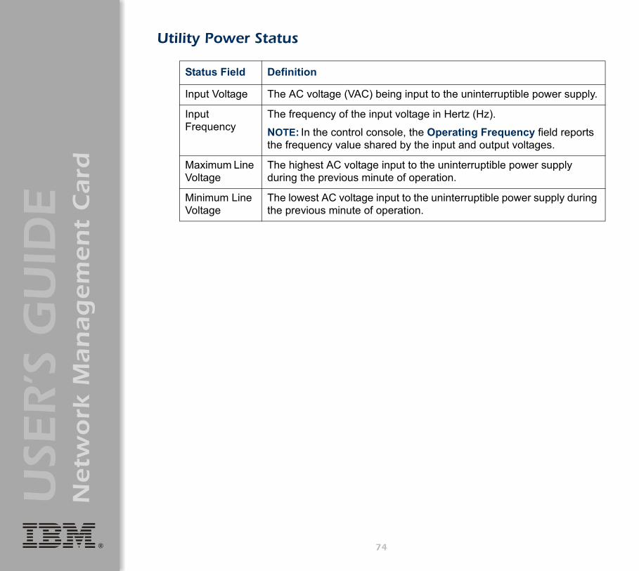
®
USE
R’S
GU
IDE
Netw
ork
Man
ag
em
en
t C
ard
Utility Power Status
Status Field Definition
Input Voltage The AC voltage (VAC) being input to the uninterruptible power supply.
Input Frequency
The frequency of the input voltage in Hertz (Hz).
NOTE: In the control console, the Operating Frequency field reports the frequency value shared by the input and output voltages.
Maximum Line Voltage
The highest AC voltage input to the uninterruptible power supply during the previous minute of operation.
Minimum Line Voltage
The lowest AC voltage input to the uninterruptible power supply during the previous minute of operation.
74

®
USE
R’S
GU
IDE
Netw
ork
Man
ag
em
en
t C
ard
Output Power Status
Status Field Definition
Output Voltage The AC voltage the uninterruptible power supply is providing to its load.
Output Frequency The frequency, in Hz, used by the output voltage.
NOTE: In the control console, the Operating Frequency field reports the frequency value shared by the input and output voltages.
Load Power The uninterruptible power supply load as a percentage of available Watts.
Apparent Load Power The power that the load of the uninterruptible power supply is using, as a percentage of available output Volt-Amps.
Load Current The current, in Amps, supplied to the load.
75

®
USE
R’S
GU
IDE
Netw
ork
Man
ag
em
en
t C
ard
Battery Status
Status Field Definition
Battery Capacity The percentage of the battery capacity of the uninterruptible power supply available to support the attached equipment.
Battery Voltage The available DC power.
Number of External Batteries How many external batteries the uninterruptible power supply has.
Runtime Remaining How long the uninterruptible power supply can use battery power to support its attached equipment.
Self-Test Result The result of the last self-test.
Self-Test Date The date when the last self-test was performed.
Calibration Result The result of the last runtime calibration.
Calibration Date When the last runtime calibration was performed.
76
®
USE
R’S
GU
IDE
Netw
ork
Man
ag
em
en
t C
ard
Diagnostics
Overview
There are two types of diagnostics options you can use with the uninterruptible power supply:
• Options that cause a specified test to occur immediately.• A scheduling option that controls when an uninterruptible power supply
self-test occurs.
Diagnostic tests
To perform diagnostic tests on the uninterruptible power supply or to display the results of the last self-test and runtime calibration:
• In the Web interface, use the Diagnostics option of the uninterruptible power supply menu.
• In the control console, use the diagnostics options of the Control menu to perform the test. For the results of the last self-test and runtime calibration, use the option Detailed Status.
77
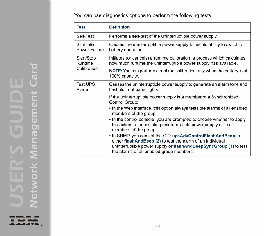
®
USE
R’S
GU
IDE
Netw
ork
Man
ag
em
en
t C
ard
You can use diagnostics options to perform the following tests.
Test Definition
Self-Test Performs a self-test of the uninterruptible power supply.
Simulate Power Failure
Causes the uninterruptible power supply to test its ability to switch to battery operation.
Start/Stop Runtime Calibration
Initiates (or cancels) a runtime calibration, a process which calculates how much runtime the uninterruptible power supply has available.
NOTE: You can perform a runtime calibration only when the battery is at 100% capacity.
Test UPS Alarm
Causes the uninterruptible power supply to generate an alarm tone and flash its front panel lights.
If the uninterruptible power supply is a member of a Synchronized Control Group:• In the Web interface, this option always tests the alarms of all enabled
members of the group.• In the control console, you are prompted to choose whether to apply
the action to the initiating uninterruptible power supply or to all members of the group.
• In SNMP, you can set the OID upsAdvControlFlashAndBeep to either flashAndBeep (2) to test the alarm of an individual uninterruptible power supply or flashAndBeepSyncGroup (3) to test the alarms of all enabled group members.
78

®
USE
R’S
GU
IDE
Netw
ork
Man
ag
em
en
t C
ard
Scheduled self-tests of the uninterruptible power supply
To schedule a self-test:• In the Web interface, select Diagnostics on the uninterruptible power
supply menu, then use the Auto Self-Test option.• In the control console, from the uninterruptible power supply menu,
select in order Configuration, General, and Self-Test Schedule.
The scheduling option enables you to control when an uninterruptible power supply self-test occurs. The available selections are Never, UPS Startup, Every 7 Days, or Every 14 Days.
79
®
USE
R’S
GU
IDE
Netw
ork
Man
ag
em
en
t C
ard
Control
Initiating an uninterruptible power supply control option
You can initiate an uninterruptible power supply control option in either of these ways:
• For the uninterruptible power supply of the initiating Network Management Card only:– In the Web interface, select No for “Apply to Sync Group?” – In the control console, type NO (in uppercase) in response to the
question “Apply command to all SCG members?” • For all members of the Synchronized Control Group to which this
Network Management Card belongs (if the option is supported for Synchronized Control Groups):– In the Web interface, select Yes for “Apply to Sync Group?”– In the control console, press Enter in response to the question
“Apply command to all SCG members?”
Guidelines for Synchronized Control Groups
The option to apply an action to a Synchronized Control Group is displayed only if this Network Management Card is an active (enabled) member of a Synchronized Control Group.
All Network Management Cards in a Synchronized Control Group must belong to uninterruptible power supplies of the same model.
To configure a Network Management Card to be a member of a Synchronized Control Group, see "Sync Control" on page 99.
80
®
USE
R’S
GU
IDE
Netw
ork
Man
ag
em
en
t C
ard
The synchronization process. If you apply an action to the Synchronization Control Group, the uninterruptible power supplies with Network Management Cards that are enabled group members behave as follows:
• Each uninterruptible power supply receives the command regardless of its output status, even if it is in a low-battery state.
• The action uses the delay periods (such as Shutdown Delay, Sleep Time, and Return Delay) that are configured for the initiating uninterruptible power supply.
• When the action begins, any uninterruptible power supply that is unable to participate retains its present output status while the other uninterruptible power supplies in the group perform the action. If an uninterruptible power supply is already in the output state that the action requires (for example, an uninterruptible power supply is already off when the Reboot UPS action starts), that uninterruptible power supply logs an event, but performs the rest of the action, if any.
• All uninterruptible power supplies participating in the action synchronize their performance of the action (within a one-second time period under ideal conditions).
• In restart and sleep actions:– Immediately before the initiating uninterruptible power supply begins
its Return Delay, by default it waits up to 120 seconds (its configurable Power Synchronized Delay) for any uninterruptible power supply that does not have input power to regain that power. Any uninterruptible power supply that fails to regain input power within the Power Synchronized Delay does not participate in the synchronized restart, but instead waits until its own input power returns before restarting.
81

®
USE
R’S
GU
IDE
Netw
ork
Man
ag
em
en
t C
ard
– The LEDs on the front of the uninterruptible power supply do not sequence their lights as they do for a normal (not synchronized) restart or sleep action.
• Uninterruptible power supply status and events are reported in the same way for synchronized actions as for actions on individual uninterruptible power supplies.
Actions (for a single uninterruptible power supply and Synchronized Control Groups). Use the actions described in the table on the next several pages for individual uninterruptible power supplies and for Synchronized Control Groups.
For more information about the delays and required battery capacity settings in the following table, see "Configuration" on page 87 and "Sync Control" on page 99.
For descriptions of the uninterruptible power supply control options Self-Test, Simulate Power Failure, Start/Stop Runtime Calibration, and Test UPS Alarm, see "Diagnostic tests" on page 77.
82

®
USE
R’S
GU
IDE
Netw
ork
Man
ag
em
en
t C
ard
.
Action Definition
Turn UPS On (control console)
This action turns on power at the uninterruptible power supply.For a Synchronized Control Group, after a delay of a few seconds, this action turns on all enabled group members that have input power.
Turn UPS Off
This action turns off the output power of the uninterruptible power supply without a shutdown delay. The uninterruptible power supply remains off until you turn on its power again.
If the uninterruptible power supply is a member of a Synchronized Control Group, this action turns off power at all uninterruptible power supplies that are enabled members of the group. No Shutdown Delay value is used. The uninterruptible power supplies turn off after a few seconds, and they remain off until you turn on their power again. See "Shutdown Parameters" on page 88.
NOTE: For a synchronized turn-off action that uses the Shutdown Delay of the initiating uninterruptible power supply, use SNMP. Set the value to turnUpsSyncGroupOffAfterDelay (5) for the upsAdvControlUpsOff OID.
Turn UPS Off Gracefully1 (control console)
This action turns off outlet power of the uninterruptible power supply after the uninterruptible power supply Maximum Shutdown Time plus two minutes, and its Shutdown Delay. See "Maximum Shutdown Time negotiation" on page 92 and "Shutdown Parameters" on page 88.
For a Synchronized Control Group, the action is performed using the delays configured for the group member that initiated the action.
1 When you select Yes for the Signal servers option of the Web interface, initiating a Turn UPS Off, Reboot UPS, or Put UPS To Sleep action is equivalent to selecting Turn UPS Off Gracefully, Reboot UPS Gracefully, or Put UPS To Sleep Gracefully in the control console.
83

®
USE
R’S
GU
IDE
Netw
ork
Man
ag
em
en
t C
ard
Reboot UPS
This action restarts the attached equipment by doing the following:• Turns off power at the uninterruptible power supply after the Shutdown
Delay.• Turns on power at the uninterruptible power supply after the battery capacity
of the uninterruptible power supply returns to at least the percentage configured for Return Battery Capacity and the uninterruptible power supply waits the time specified as Return Delay. See "Shutdown Parameters" on page 88.
For a Synchronized Control Group action:• This action turns off power at the uninterruptible power supplies that are
enabled group members after waiting the time configured as Shutdown Delay of the initiating uninterruptible power supply. See "Shutdown Parameters" on page 88.
• The initiating uninterruptible power supply then waits up to the number of seconds specified as Power Synchronized Delay to allow time for group members to regain input power. If all group members have already regained input power, this delay is omitted. If all group members regain input power during the delay, the remainder of the delay is cancelled. To configure the Power Synchronized Delay, see "Configure Synchronized Control" on page 100.
• The Return Delay then starts when the initiating uninterruptible power supply is at its configured Return Battery Capacity. See "Shutdown Parameters" on page 88.
• The Return Battery Capacity of the initiating uninterruptible power supply is also required of group members, but you can reduce the capacity required of a group member by configuring Return Battery Capacity Offset (set at 10% by default) for that member. For example, if Return Battery Capacity of the initiator is set at 50%, and Return Battery Capacity Offset of a member is set to 5%, that battery capacity of that member will need to be at only 45% for that member to restart. See "Configure Synchronized Control" on page 100.
Action Definition
1 When you select Yes for the Signal servers option of the Web interface, initiating a Turn UPS Off, Reboot UPS, or Put UPS To Sleep action is equivalent to selecting Turn UPS Off Gracefully, Reboot UPS Gracefully, or Put UPS To Sleep Gracefully in the control console.
84

®
USE
R’S
GU
IDE
Netw
ork
Man
ag
em
en
t C
ard
Reboot UPS Gracefully1
(control console)
This action is performed similarly to the Reboot UPS action, but with an additional delay before the shutdown portion of the action. The attached equipment shuts down only after the uninterruptible power supply (or the initiating uninterruptible power supply for a Synchronized Control Group action) waits the Maximum Shutdown Time plus two minutes. For information about how the Maximum Shutdown Time is determined, see "Maximum Shutdown Time negotiation" on page 92.
Put UPS To Sleep
This action puts the uninterruptible power supply into sleep mode by turning off its output power for a defined period of time, as follows:• The uninterruptible power supply turns off output power after waiting the time
configured as its Shutdown Delay. See "Shutdown Parameters" on page 88.
• When input power returns, the uninterruptible power supply turns on output power after two configured periods of time, its Sleep Time and Return Delay. See "Shutdown Parameters" on page 88.
• For a synchronized control group action, the Network Management Card of the uninterruptible power supply initiating the action waits up to the number of seconds configured as its Power Synchronized Delay for enabled group members to regain input power before it starts the Return Delay. If all group members have already regained input power, the Power Synchronized Delay is omitted. If all group members regain input power during the delay, the remainder of the delay is cancelled. See "Configure Synchronized Control" on page 100.
Action Definition
1 When you select Yes for the Signal servers option of the Web interface, initiating a Turn UPS Off, Reboot UPS, or Put UPS To Sleep action is equivalent to selecting Turn UPS Off Gracefully, Reboot UPS Gracefully, or Put UPS To Sleep Gracefully in the control console.
85
®
USE
R’S
GU
IDE
Netw
ork
Man
ag
em
en
t C
ard
Put UPS To Sleep Gracefully1 (control console)
This action puts the uninterruptible power supply into sleep mode (turns off power for a defined period of time), as follows:• The uninterruptible power supply turns off output power after waiting the
delay time configured as its Maximum Shutdown Time plus 2 minutes (to allow time for PowerChute Network Shutdown to shut down its server safely) and its Shutdown Delay. See "Maximum Shutdown Time negotiation" on page 92 and "Shutdown Parameters" on page 88.
• When input power returns, the uninterruptible power supply turns on output power after two configured periods of time, its Sleep Time and Return Delay. See "Shutdown Parameters" on page 88.
• For a Synchronized Control Group action, the Network Management Card of the uninterruptible power supply initiating the action waits up to the number of seconds configured as its Power Synchronized Delay for enabled group members to regain input power before it starts the Return Delay. If all group members have already regained input power, the Power Synchronized Delay is omitted. If all group members regain input power during the delay, the remainder of the delay is cancelled. See "Configure Synchronized Control" on page 100.
Put UPS in Bypass/Take UPS Off Bypass
Controls the use of bypass mode, which allows maintenance to be performed at the uninterruptible power supply without turning off power at the uninterruptible power supply.
Action Definition
1 When you select Yes for the Signal servers option of the Web interface, initiating a Turn UPS Off, Reboot UPS, or Put UPS To Sleep action is equivalent to selecting Turn UPS Off Gracefully, Reboot UPS Gracefully, or Put UPS To Sleep Gracefully in the control console.
86

®
USE
R’S
GU
IDE
Netw
ork
Man
ag
em
en
t C
ard
Configuration
Overview
The Configuration option of the uninterruptible power supply menu provides access to the configurable parameters described in the following sections:
• "Utility Line Settings" on this page.• "Shutdown Parameters" on page 88.• "General Settings (Configuration)" on page 89.• "Reset UPS Defaults" on page 89.
Utility Line Settings
Setting Definition
Output Voltage The nominal AC voltage level for the uninterruptible power supply output.
Bypass Upper Voltage
The input voltage above which the uninterruptible power supply cannot switch to bypass mode.
Bypass Lower Voltage
The input voltage below which the uninterruptible power supply cannot switch to bypass mode.
Sensitivity How sensitive the uninterruptible power supply will be to distortions in the input voltage.
87

®
USE
R’S
GU
IDE
Netw
ork
Man
ag
em
en
t C
ard
Shutdown Parameters
NoteIn the control console, use the Battery option in the Configuration menu to access the Return Battery Capacity setting.
Setting Definition
Return Battery Capacity
Defines the minimum battery capacity required before the uninterruptible power supply turns on after a shutdown that was caused by a power failure.
NOTE: The uninterruptible power supply must also wait the time defined by the Return Delay setting before it can turn on.
Low-Battery Duration
Defines how long the uninterruptible power supply can continue to run on battery power after a low-battery condition occurs.
NOTE: This setting also defines the time available for PowerChute to shut down its server safely in response to the Control options Turn UPS Off Gracefully, Reboot UPS Gracefully, and Put UPS To Sleep Gracefully.
Maximum Shutdown Time (Web interface only)
Reports the delay that is defined by the Maximum Shutdown Time setting for the PowerChute Network Shutdown feature.
NOTE: For information about the PowerChute Network Shutdown feature, see "PowerChute (PowerChute Network Shutdown)" on page 90; for information about how the Maximum Shutdown Time is determined, see "Maximum Shutdown Time negotiation" on page 92.
Shutdown Delay
Defines how long the uninterruptible power supply waits before it shuts down in response to a turn-off command.
Return Delay
Defines how long the uninterruptible power supply waits before it turns on after a shutdown that was caused by a power failure.
NOTE: The uninterruptible power supply must also have the capacity specified by the Return Battery Capacity setting before it can turn on.
Sleep Time
Defines how long the uninterruptible power supply sleeps (keeps its output power turned off) when you use either of the sleep options in the Control menu (Put UPS To Sleep or Put UPS To Sleep Gracefully).
NOTE: This setting also is in the Control page of the Web interface.
88
®
USE
R’S
GU
IDE
Netw
ork
Man
ag
em
en
t C
ard
General Settings (Configuration)
Reset UPS DefaultsThis option resets the uninterruptible power supply to use the default EEPROM values.
NoteIn the control console, use the Battery option in the Configuration menu to access the Last Battery Replacement and External Batteries settings.
Setting Definition
UPS Name Defines the name of the uninterruptible power supply.
Last Battery Replacement
Defines the date of the most recent uninterruptible power supply battery replacement. NOTE: Use mm/dd/yy format.
Self-Test Schedule (control console only)
Schedules when and how frequently an uninterruptible power supply self-test occurs. See "Scheduled self-tests of the uninterruptible power supply" on page 79.
Audible Alarm Defines when the uninterruptible power supply generates an alarm in response to switching to battery operation.
External Batteries Defines how many external battery packs are connected to the uninterruptible power supply. The uninterruptible power supply cannot automatically sense and report the number of connected battery packs.
Simple Signal Shutdowns
When enabled, allows simple-signalling shutdown through PowerChute Network Shutdown.
UPS Position The physical orientation of the uninterruptible power supply.
Attention!
Before you use this option, make sure that resetting the EEPROM values will not adversely affect the load equipment or any shutdown sequence.
89

®
USE
R’S
GU
IDE
Netw
ork
Man
ag
em
en
t C
ard
PowerChute (PowerChute Network Shutdown)
Overview
The PowerChute option of the uninterruptible power supply menu in the Web interface enables you to use the PowerChute Network Shutdown utility to shut down as many as 50 servers on your network that are using any client version of PowerChute Network Shutdown.
For more information about PowerChute Network Shutdown, see the PowerChute Network Shutdown Installation Guide and the PowerChute Network Shutdown Release Notes, provided on the Network Management Card CD.
90

®
USE
R’S
GU
IDE
Netw
ork
Man
ag
em
en
t C
ard
PowerChute Network Shutdown Parameters
Parameter Definition
Maximum Shutdown Time
Defines the maximum time that the uninterruptible power supply at a PowerChute Network Shutdown client waits before it shuts down in response to a graceful turn-off command.
NOTE: For information about how this shutdown delay is determined, see "Maximum Shutdown Time negotiation" on page 92.
Shutdown Behavior Defines how the uninterruptible power supply turns off after the PowerChute Network Shutdown clients finish shutting down their computer systems.
Add Client IP Address Enables you to add as many as 50 PowerChute Network Shutdown clients to the Configured Client IP Addresses list.
NOTE: When you install a PowerChute Network Shutdown client on your network, it is added to the list automatically.
Configured Client IP Addresses
Enables you to view the list of PowerChute Network Shutdown clients, and remove PowerChute Network Shutdown clients from the list.
NOTE: When you uninstall a PowerChute Network Shutdown client, it is removed from the list automatically.
91

®
USE
R’S
GU
IDE
Netw
ork
Man
ag
em
en
t C
ard
Maximum Shutdown Time negotiation
The Maximum Shutdown Time setting provides the delay needed to make sure that a server has enough time to shut down safely when the Network Management Card or PowerChute Network Shutdown client initiates a graceful shutdown at that server.
The time reported in the Maximum Shutdown Time field represents the maximum delay needed by at least one of the servers listed in the Configured Client IP Addresses list. This time is determined by a negotiation process that is initiated when any of the following occurs:
• The Network Management Card turns on (a System: Coldstart event).• The Network Management Card is reset (a System: Warmstart event).• You select Force negotiation from the drop-down list for the
Maximum Shutdown Time field, and click Apply.
During the negotiation process, which can take up to 10 minutes, each server listed in the Configured Client IP Addresses is contacted to determine the shutdown delay needed by that server. The delay time defined by the Maximum Shutdown Time setting will be changed, if necessary, to the highest delay time reported by the servers.
For example:• If 3 minutes was the result of the last negotiation process, and a new
server that requires a 4-minute shutdown delay has been added to the Configured Client IP Addresses list, 4 minutes will be the new Maximum Shutdown Time.
For information about the Turn UPS Off Gracefully, Reboot UPS Gracefully, and Put UPS To Sleep Gracefully options that use this delay for uninterruptible power supplies and Synchronized Control Groups, see "Control" on page 80.
92
®
USE
R’S
GU
IDE
Netw
ork
Man
ag
em
en
t C
ard
• If none of the servers needs more than a 2-minute delay, 2 minutes will be the Maximum Shutdown Time setting.
Note
At the end of the negotiation process, the two-minute time period is added to the calculated total for Maximum Shutdown Time to allow for any unusual delays that might occur in notifying servers to shut down.
93

®
USE
R’S
GU
IDE
Netw
ork
Man
ag
em
en
t C
ard
Scheduling Uninterruptible Power Supply Shutdown
Overview
This option is available in the Web interface only.
You can schedule shutdowns on a daily, weekly or one-time basis, and you can schedule them for a single uninterruptible power supply or for all uninterruptible power supplies in a Synchronized Control Group.
For more information about how to use this option, see the following sections:
• "Examples" on page 95.• "How to schedule a shutdown" on page 96.• "How to schedule a synchronized shutdown" on page 97.• "How to edit, disable, or delete a shutdown" on page 98.
94
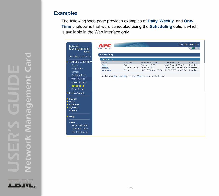
®
USE
R’S
GU
IDE
Netw
ork
Man
ag
em
en
t C
ard
Examples
The following Web page provides examples of Daily, Weekly, and One-Time shutdowns that were scheduled using the Scheduling option, which is available in the Web interface only.
95

®
USE
R’S
GU
IDE
Netw
ork
Man
ag
em
en
t C
ard
How to schedule a shutdown
Click the Daily, Weekly, or One-Time option to choose the type of shutdown, and then use the following fields:
1. Use Name of Scheduled Shutdown to define a name for the shutdown.
2. Use Shutdown to define when the shutdown will begin.3. Use Turn back on to define whether the uninterruptible power supply
will turn on at a specific day and time, Never (the uninterruptible power supply will be turned on manually), or Immediately (the uninterruptible power supply will turn on after a six-minute delay).
4. Select whether PowerChute servers will be warned before the shutdown begins.
5. Click Apply.
96

®
USE
R’S
GU
IDE
Netw
ork
Man
ag
em
en
t C
ard
How to schedule a synchronized shutdown
To use the Web interface of the Network Management Card to schedule shutdowns within a Synchronized Control Group, always schedule all shutdowns through the same member of the group.
The following guidelines apply to Synchronized Control Groups:• All Network Management Cards in a Synchronized Control Group must
be of the same uninterruptible power supply model.• For a scheduled uninterruptible power supply shutdown to occur, a
network connection to the uninterruptible power supply must exist at the time at which the action is scheduled to occur.
All scheduled shutdowns will be synchronized when the Network Management Card that initiates the shutdown is a member of a Synchronized Control Group and its status as a group member is enabled.
Attention!
Scheduled shutdowns through more than one group member is not a supported configuration and may cause unpredictable results.
97
®
USE
R’S
GU
IDE
Netw
ork
Man
ag
em
en
t C
ard
How to edit, disable, or delete a shutdown
Click a listed shutdown to display the Daily Shutdown Detail page. Use this page to do the following:
• View a summary of the shutdown, including information about the values for settings that can affect how the uninterruptible power supply shuts down and turns on again:– For information about Maximum Shutdown Time, a PowerChute
option, see "Maximum Shutdown Time negotiation" on page 92.– For information about Shutdown Delay and Return Delay, see
"Shutdown Parameters" on page 88.• Change any shutdown parameter.• Use Status of Scheduled Shutdown to enable, disable or delete the
shutdown.
98
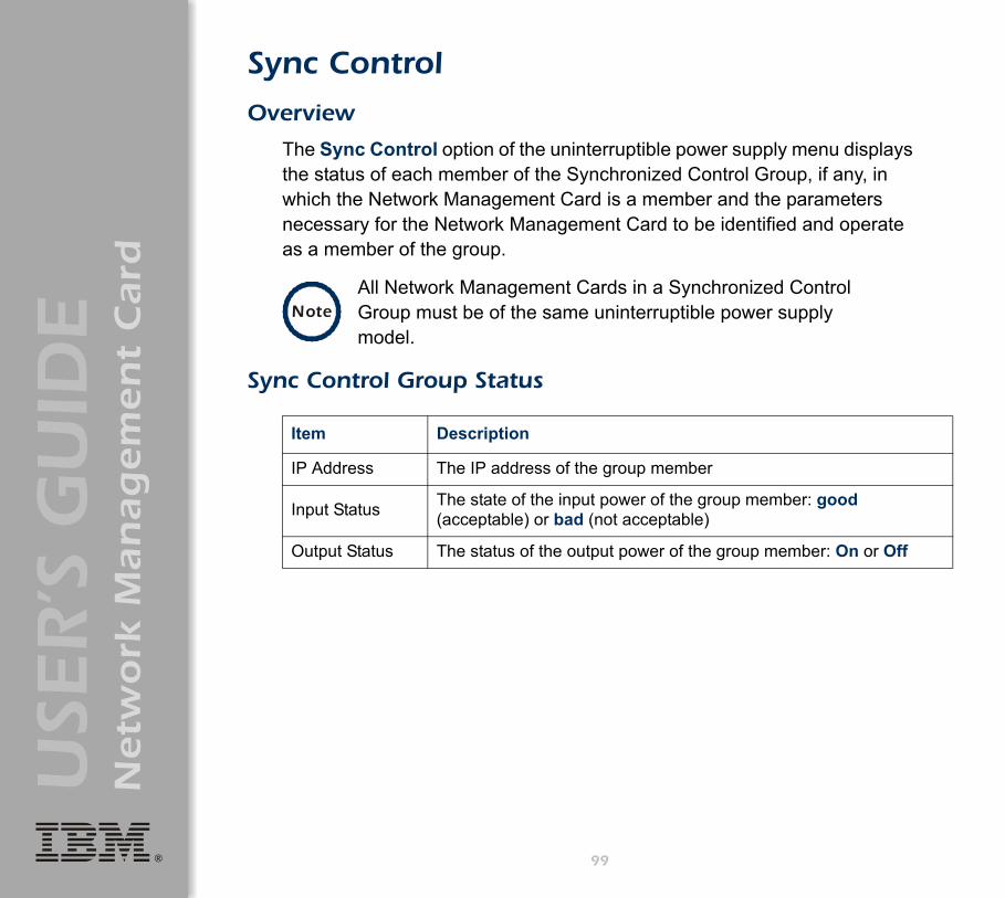
®
USE
R’S
GU
IDE
Netw
ork
Man
ag
em
en
t C
ard
Sync Control
Overview
The Sync Control option of the uninterruptible power supply menu displays the status of each member of the Synchronized Control Group, if any, in which the Network Management Card is a member and the parameters necessary for the Network Management Card to be identified and operate as a member of the group.
Sync Control Group Status
NoteAll Network Management Cards in a Synchronized Control Group must be of the same uninterruptible power supply model.
Item Description
IP Address The IP address of the group member
Input Status The state of the input power of the group member: good (acceptable) or bad (not acceptable)
Output Status The status of the output power of the group member: On or Off
99

®
USE
R’S
GU
IDE
Netw
ork
Man
ag
em
en
t C
ard
Configure Synchronized Control
Parameter Description
Synchronized Group Membership
Determines whether this Synchronized Control Group member is an active member of its group. If you set this value to Disabled (the default value), the Network Management Card ignores all Synchronized Control Group commands, and its uninterruptible power supply functions as if it were not a member of any Synchronized Control Group.
Synchronized Control Group Number
The unique identifier of the Synchronized Control Group of which this Network Management Card is a member. This value must be a number from 1 through 65534. The Network Management Card of an uninterruptible power supply can be a member of only one Synchronized Control Group. All members of a Synchronized Control Group must have the same Synchronized Control Group Number and Multicast IP Address.
Power Synchronized Delay
The maximum time (120 seconds by default) that the initiating uninterruptible power supply of a synchronized sleep or restart action will wait for other group members to regain input power when the initiating uninterruptible power supply is ready to turn on.• For a synchronized restart, the initiating uninterruptible power supply waits
up to this delay period for other group members to regain input power, then waits until its return battery capacity is reached, and then begins the Return Delay. The Power Synchronized Delay does not occur if all group members have input power immediately after they turn off for the restart.
• For a synchronized sleep command, after the configured sleep time expires, the initiating uninterruptible power supply waits up to this delay period for other group members to regain input power, and then begins the Return Delay. The Power Synchronized Delay does not occur if all group members have input power after the sleep time expires.
100
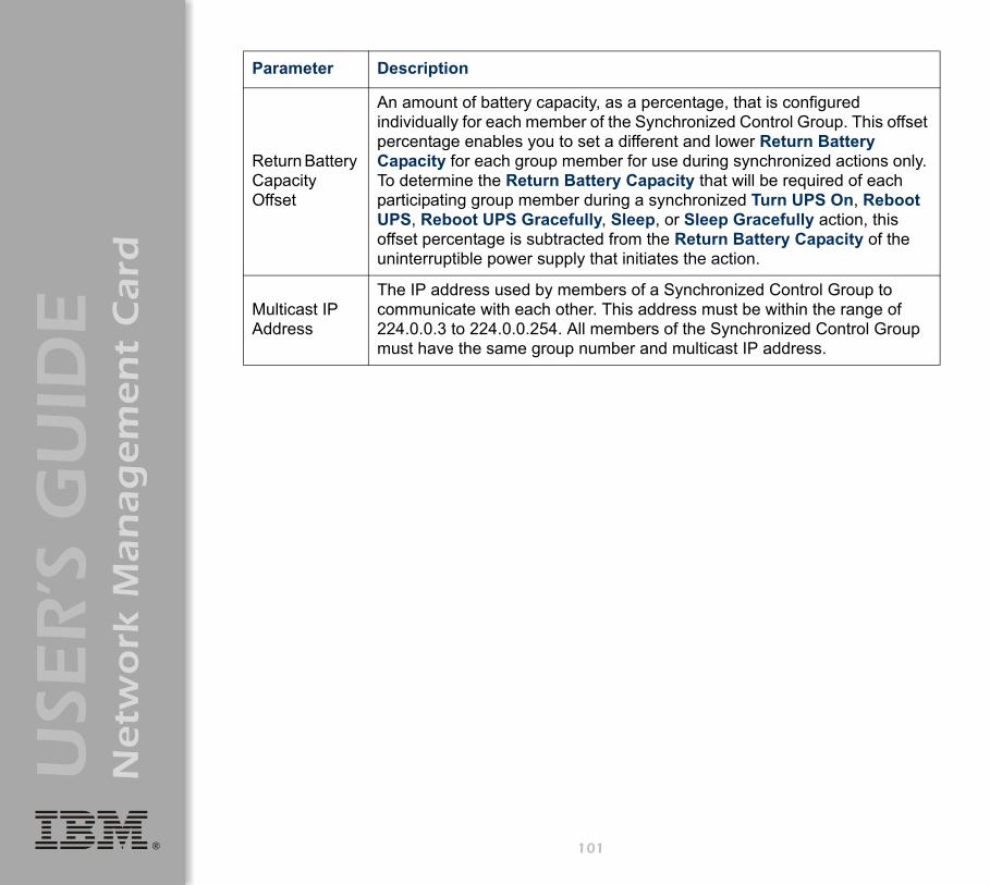
®
USE
R’S
GU
IDE
Netw
ork
Man
ag
em
en
t C
ard
Return Battery Capacity Offset
An amount of battery capacity, as a percentage, that is configured individually for each member of the Synchronized Control Group. This offset percentage enables you to set a different and lower Return Battery Capacity for each group member for use during synchronized actions only. To determine the Return Battery Capacity that will be required of each participating group member during a synchronized Turn UPS On, Reboot UPS, Reboot UPS Gracefully, Sleep, or Sleep Gracefully action, this offset percentage is subtracted from the Return Battery Capacity of the uninterruptible power supply that initiates the action.
Multicast IP Address
The IP address used by members of a Synchronized Control Group to communicate with each other. This address must be within the range of 224.0.0.3 to 224.0.0.254. All members of the Synchronized Control Group must have the same group number and multicast IP address.
Parameter Description
101

®
USE
R’S
GU
IDE
Netw
ork
Man
ag
em
en
t C
ard
Environment Menu
Introduction
Overview
Use the Environment menu in the Web interface or control console to manage the Integrated Environmental Monitor of a Network Management Card. (In the control console, the Environment menu is an option of the Device Manager menu.) When you select the Environment option in the control console, two options are displayed:
1- Integrated Environmental Monitor Settings2- External Environmental Monitor Settings
Only option 1, for the Integrated Environmental Monitor, is supported for the IBM UPS 7500XHV and the IBM UPS 10000XHV.
Environment menu options
Two basic types of options are available:• "Status Options" on page 103.• "Settings Options" on page 105.
Note
In the control console, the Integrated Environmental Monitor Settings menu has an About Environmental Monitor option that accesses firmware information for the Integrated Environmental Monitor of the Network Management Card.
The Web interface provides this firmware information on the Environmental Monitor Status page.
102

®
USE
R’S
GU
IDE
Netw
ork
Man
ag
em
en
t C
ard
Status Options
Overview
The summary page of the Web interface displays basic status information about the thresholds, contacts, and output relay of the Integrated Environmental Monitor of the Network Management Card.
Use the Status option in the Environment menu to access detailed status about these environmental monitor components, including how the current temperature readings relate to their high and low thresholds.
In the control console, basic status information is displayed above the Control Console and Environmental Monitor Settings menus. Use Detailed Status in the Integrated Environmental Monitor Settings menu for detailed status of the Integrated Environmental Monitor components.
The Web interface uses icons to identify faults that exist at the Integrated Environmental Monitor. For information about these status icons, see "Quick status tab" on page 29.
103

®
USE
R’S
GU
IDE
Netw
ork
Man
ag
em
en
t C
ard
Probe status
The Web interface uses a temperature graph to identify whether the reported value exceeds a low (blue) or high (red) threshold for the Integrated Environmental Monitor probe.
In the control console, the status options in the Integrated Environmental Monitor Settings menus report the high and low thresholds for the temperature probe of the Integrated Environmental Monitor and report any violations of those thresholds.
Contact status
The Web interface reports the current state (Disabled, No Fault, or Fault Present) for each identified input contact. The Integrated Environmental Monitor of the Network Management Card supports two contacts.
In the control console, the status options in the Integrated Environmental Monitor Settings menu reports the current fault condition for the contacts of the Integrated Environmental Monitor.
Output relay status
The Web interface reports the current state of the output relay of the Integrated Environmental Monitor of the Network Management Card.
In the control console, the Output Relay option in the Integrated Environmental Monitor menu reports the current condition.
104

®
USE
R’S
GU
IDE
Netw
ork
Man
ag
em
en
t C
ard
Settings Options
Probe settings
In the Web interface, use the Probes option in the Environment menu to access the following fields:
• Setting fields that define a name (16-character maximum) and high and low temperature thresholds, for the temperature probe of the Integrated Environmental Monitor.
• Event Generation fields that enable or disable the generation of an event when a selected threshold violation occurs.
In the control console, use the Probe Settings option in the Integrated Environmental Monitor Settings menu to define the probe name, temperature thresholds, and event generation settings for the Integrated Environmental Monitor.
Contact settings
In the Web interface, use the Input Contacts option in the Environment menu to access the following fields:
• Name fields to define the name for each contact alarm (16-character maximum).
• Event Generation fields to enable or disable each alarm.
In the control console, use the Contact Settings options in the Integrated Environmental Monitor Settings menu to access these settings.
105

®
USE
R’S
GU
IDE
Netw
ork
Man
ag
em
en
t C
ard
Output relay settings
To access the following settings:• In the Web interface, use the Output Relay option in the Environment
menu.• In the control console, use the Output Relay Settings option in the
Integrated Environmental Monitor menu.
Setting Definition
Output Relay (Web interface)
Relay Name (control console)
Defines a description of the purpose of the output relay (16-character maximum).
Switch When (Web interface)
Switch Relay When (control console)
Selects the event that will activate the output relay (or disables the action).
Delay (Web interface)
Switch to Relay Delay (control console)
Defines how long in seconds the event that is selected to activate the output relay must be present before the output relay is activated.
Hold (Web interface)
Relay Hold Time (control console)
Defines the minimum number of seconds that the output relay will remain activated after its activating event occurs.
106

®
USE
R’S
GU
IDE
Netw
ork
Man
ag
em
en
t C
ard
Event-Related Menus
Introduction
Overview
Use the options of the Events menu to do the following tasks:• Access the event log.• Define the actions to be taken when an event occurs, based on the
severity level of that event: (You must use the Web interface to define which events will use which actions.)– Event logging.– Syslog messages.– SNMP trap notification.– E-mail notification.
• Define up to four SNMP trap receivers, by NMS-specific IP address or domain name, for event notifications by SNMP traps.
• Define up to four recipients for event notifications by e-mail.
To define which events will use which actions, see "Event Log" on page 109 and "How to Configure Individual Events" on page 126.
107
®
USE
R’S
GU
IDE
Netw
ork
Man
ag
em
en
t C
ard
Menu options
To access the event-related options:• In the Web interface, use the Events menu. • In the control console:
– Use the Email option in the Network menu to define the SMTP server and e-mail recipients.
– Use the SNMP option in the Network menu to define the SNMP trap receivers.
– Press Ctrl+L to access the event log from any menu.
For information about event-related settings and about the e-mail feature, see the following descriptions:
• "Event Log" on page 109.• "Event Actions (Web Interface Only)" on page 115.• "Event Recipients" on page 118.• "E-mail Feature" on page 120.• "How to Configure Individual Events" on page 126.
108
®
USE
R’S
GU
IDE
Netw
ork
Man
ag
em
en
t C
ard
Event Log
Overview
The Network Management Card supports event logging for all uninterruptible power supply application firmware modules. You can record and view uninterruptible power supply and Network Management Card events.
Use any of the following to view the event log:• Web interface • Control console• FTP• SCP
109

®
USE
R’S
GU
IDE
Netw
ork
Man
ag
em
en
t C
ard
Logged events
By default, the following events are logged:• Any event that causes an SNMP trap, except for SNMP authentication
failures.• The abnormal internal system events of the Network Management
Card.
To disable the logging of events based on their assigned severity level, use the Actions option in the Events menu of the Web interface.
Even if you disable the event log for all severity levels, some System (Network Management Card) events will still be logged because some of those events have no severity level.
Web interface
The Log option in the Events menu accesses the event log, which displays all of the events that have been recorded since the log was last deleted, in reverse chronological order. The Delete Log button clears all events from the log.
See "Event Actions (Web Interface Only)" on page 115.
See "Event List page" on page 126 to access a list of all configurable events (uninterruptible power supply and Network Management Card) that indicates which events and how many events have been configured individually.
Note
The event log will log a graceful shutdown of the uninterruptible power supply, even when that shutdown was not initiated by the Network Management Card; a graceful shutdown from Serial Port 1 typically indicates that PowerChute performed the shutdown.
110
®
USE
R’S
GU
IDE
Netw
ork
Man
ag
em
en
t C
ard
Control console
In the control console, press Ctrl+L to display all the events that have been recorded since the log was last deleted, in reverse chronological order. Use the Space Bar to scroll through the recorded events.
While viewing the log, type d and press Enter to clear all events from the log.
Note Deleted events cannot be retrieved.
111

®
USE
R’S
GU
IDE
Netw
ork
Man
ag
em
en
t C
ard
How to use FTP or SCP to retrieve log files
If you are an Administrator or Device Manager, you can use FTP or SCP to retrieve a tab-delineated event log file (event.txt) or data log file (data.txt) that you can import into a spreadsheet application:
• The file reports all of the events or data recorded since the log was last deleted.
• The file includes information that the event log or data log does not display:– The version of the file format (first field).– The date and time the file was retrieved.– The Name, Contact, and Location values and IP address of the
Network Management Card.– The unique Event Code for each recorded event (event.txt file only).
If you are using the encryption-based security protocols for your system, use Secure CoPy (SCP) to retrieve the log file. (You should have FTP disabled.)
If you are using unencrypted authentication methods for the security of your system, use FTP to retrieve the log file.
Note
The Network Management Card uses a four-digit year for log entries. You may need to select a four-digit date format in your spreadsheet application to display all four digits of the year.
See "Security" on page 139 for information on the available protocols and methods for setting up the type of security appropriate for your needs.
112

®
USE
R’S
GU
IDE
Netw
ork
Man
ag
em
en
t C
ard
To use SCP to retrieve the files. To use SCP to retrieve the event.txt file, use the following command:
scp username@hostname_or_ip_address:event.txt ./event.txt
To use SCP to retrieve the data.txt file, use the following command:scp username@hostname_or_ip_address:data.txt ./data.txt
To use FTP to retrieve the files. To use FTP to retrieve the event.txt or data.txt file:
1. At a command prompt, type ftp and the IP address of the Network Management Card, and press Enter.If the Port setting for FTP Server in the Network menu has changed from its default value (21), you must use the non-default value in the FTP command. For Windows FTP clients, use the following command, including spaces. (For some FTP clients, you must use a colon instead of a space between the IP address and the port number.)ftp>open ip_address port_number
2. Use the case-sensitive user name and password for either an Administrator or a Device Manager user to log on:– For Administrator, apc is the default user name and password.– For Device Manager, device is the default user name, and apc is
the default password.3. Use the get command to transmit the text-version of the event log or
data log to your local drive.ftp>get event.txt
or
ftp>get data.txt
To use non-default port values to enhance security, see "Port assignments" on page 141.
113

®
USE
R’S
GU
IDE
Netw
ork
Man
ag
em
en
t C
ard
4. You can use the del command to clear the contents of the event log or data log.ftp>del event.txt
or
ftp>del data.txt
You will not be asked to confirm the deletion: – If you clear the data log, the event log records a deleted-log event.– If you clear the event log, a new event.txt file is created to record the
deleted-log event.5. Type quit at the ftp> prompt to exit from FTP.
114

®
USE
R’S
GU
IDE
Netw
ork
Man
ag
em
en
t C
ard
Event Actions (Web Interface Only)
Overview
Use the Actions option in the Events menu to do the following:• Select which actions will occur for events that have a severity level:
– Event Log selects which severity levels cause an event to be logged.
– Syslog selects which severity levels cause messages to be sent to Syslog servers to log events.
– SNMP Traps selects which severity levels generate SNMP traps, and which trap receivers are notified for events of each severity level.
– Email selects which severity levels cause e-mail notifications and which e-mail recipients receive e-mail for events of each severity level.
• Click Details for a complete list of Network Management Card (System) and uninterruptible power supply events that can occur, and then edit the actions that will occur for an individual event. Click Hide Details to return to the Actions option.
See "Event Log action" on page 116.
See "Syslog action" on page 117.
See "SNMP Traps action" on page 117.
See "Email action" on page 117.
See "How to Configure Individual Events" on page 126.
115

®
USE
R’S
GU
IDE
Netw
ork
Man
ag
em
en
t C
ard
Severity levels
Except for some System (Network Management Card) events that do not have a severity level, events are assigned a default severity level:
• Informational: Indicates an event that requires no action, such as a notification of a return from an abnormal condition.
• Warning: Indicates an event that may need to be addressed if the condition continues, but which does not require immediate attention.
• Severe: Indicates an event that requires immediate attention. Unless resolved, severe uninterruptible power supply and Network Management Card events can cause incorrect operation of the uninterruptible power supply or its supported equipment, or can result in the loss of uninterruptible power supply protection during a power failure.
Event Log action
To stop logging events that have a severity level, disable the Event Log action. System (Network Management Card) events that have no severity level will still be logged. By default, all events are logged, even events that have no severity level.
For more information about the log, see "Event Log" on page 109.
116

®
USE
R’S
GU
IDE
Netw
ork
Man
ag
em
en
t C
ard
Syslog action
By default, the Syslog action is enabled for all events that have a severity level. However, before you can use this feature to send Syslog messages when events occur, you must configure it.
SNMP Traps action
By default, the SNMP Traps action is enabled for all events that have a severity level. However, before you can use SNMP traps for event notification, you must identify the NMSs (by their IP addresses or domain names) that will receive the traps.
Email action
By default, the Email action is enabled for all events that have a severity level. However, before you can use e-mail for event notification, you must define the e-mail recipients.
See "Syslog" on page 52.
To define up to four NMSs as trap receivers, see "Event Recipients" on page 118.
See "E-mail Feature" on page 120.
117
®
USE
R’S
GU
IDE
Netw
ork
Man
ag
em
en
t C
ard
Event Recipients
Overview
Use the Web interface or control console to define up to four trap receivers, four e-mail addresses, and four paging recipients to be used when an event occurs that has SNMP, e-mail, or paging enabled, as described in "Event Actions (Web Interface Only)" on page 115.
To identify the servers that will receive Syslog messages, see "Syslog" on page 52.
118
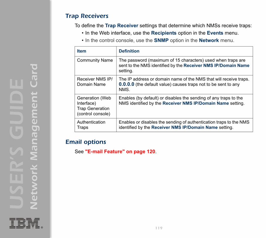
®
USE
R’S
GU
IDE
Netw
ork
Man
ag
em
en
t C
ard
Trap Receivers
To define the Trap Receiver settings that determine which NMSs receive traps:• In the Web interface, use the Recipients option in the Events menu.• In the control console, use the SNMP option in the Network menu.
Email options
See "E-mail Feature" on page 120.
Item Definition
Community Name The password (maximum of 15 characters) used when traps are sent to the NMS identified by the Receiver NMS IP/Domain Name setting.
Receiver NMS IP/Domain Name
The IP address or domain name of the NMS that will receive traps. 0.0.0.0 (the default value) causes traps not to be sent to any NMS.
Generation (Web Interface)Trap Generation (control console)
Enables (by default) or disables the sending of any traps to the NMS identified by the Receiver NMS IP/Domain Name setting.
Authentication Traps
Enables or disables the sending of authentication traps to the NMS identified by the Receiver NMS IP/Domain Name setting.
119
®
USE
R’S
GU
IDE
Netw
ork
Man
ag
em
en
t C
ard
E-mail Feature
Overview
Use the Simple Mail Transfer Protocol (SMTP) to send e-mail to up to four recipients when an event occurs.
To use the e-mail feature, you must define the following settings:• The IP addresses of the primary and secondary Domain Name System
(DNS) servers.
• The DNS name of the SMTP Server and the From Address settings for SMTP.
• The e-mail addresses for a maximum of four recipients.
See "DNS servers" on page 121.
See "SMTP settings" on page 122.
See "Email Recipients" on page 123.
NoteYou can use the To Address setting of the Email Recipients option to send e-mail to a text-based pager.
120
®
USE
R’S
GU
IDE
Netw
ork
Man
ag
em
en
t C
ard
DNS servers
The Network Management Card cannot send any e-mail messages unless at least the IP address of the primary DNS server is defined.
The Network Management Card will wait a maximum of 15 seconds for a response from the primary DNS server or the secondary DNS server (if a secondary DNS server is specified). If the Network Management Card does not receive a response within that time, e-mail cannot be sent. Therefore, use DNS servers that are on the same segment as the Network Management Card, or on a nearby segment (but not across a wide-area network (WAN).
After you define the IP addresses of the DNS servers, verify that DNS is working correctly by entering the DNS name of a computer on your network to look up the IP address for computer.
See "DNS" on page 39.
121
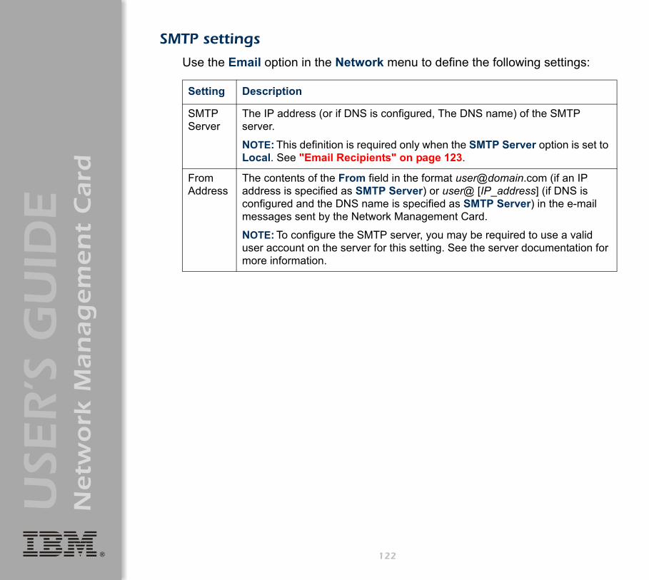
®
USE
R’S
GU
IDE
Netw
ork
Man
ag
em
en
t C
ard
SMTP settings
Use the Email option in the Network menu to define the following settings:
Setting Description
SMTP Server
The IP address (or if DNS is configured, The DNS name) of the SMTP server.
NOTE: This definition is required only when the SMTP Server option is set to Local. See "Email Recipients" on page 123.
From Address
The contents of the From field in the format [email protected] (if an IP address is specified as SMTP Server) or user@ [IP_address] (if DNS is configured and the DNS name is specified as SMTP Server) in the e-mail messages sent by the Network Management Card.
NOTE: To configure the SMTP server, you may be required to use a valid user account on the server for this setting. See the server documentation for more information.
122

®
USE
R’S
GU
IDE
Netw
ork
Man
ag
em
en
t C
ard
Email Recipients
In the Web interface, use the Recipients option in the Events menu or the Configure the Email recipients link in the Email Configuration page to identify up to four e-mail recipients. Use the Email Test option to send a test message to a configured recipient.
In the control console, use the Email option in the Network Menu, to access the e-mail recipient settings.
123

®
USE
R’S
GU
IDE
Netw
ork
Man
ag
em
en
t C
ard
Setting Description
To Address
Defines the user and domain names of the recipient.
You can bypass the DNS lookup of the IP address of the mail server by using the IP address in brackets instead of the e-mail domain name. For example, use jsmith@[xxx,xxx.x.xxx] instead of [email protected]. This is useful when DNS lookups are not working correctly
To use e-mail for paging, use the e-mail address for that recipient’s pager gateway account (for example, [email protected]). The pager gateway will generate the page.
NOTE: The recipient’s pager must be able to use text-based messaging.
Use SMTP Server
Selects one of the following methods for routing e-mail:• Through the SMTP server of the Network Management Card (the
recommended option is Local). This option ensures that the e-mail is sent before the 20-second time-out of the Network Management Card, and, if necessary, is retried several times. Also do one of the following: • Enable forwarding at the SMTP server of the Network Management
Card so that it can route e-mail to external SMTP servers. Typically, SMTP servers are not configured to forward e-mail. Always check with the administrator of your SMTP server before changing its configuration to enable forwarding.
• Set up a special e-mail account for the Network Management Card to forward e-mail to an external mail account.
• Directly to the recipient’s SMTP server (the Recipient’s option). On a busy remote SMTP server, the time-out may prevent some e-mail from being sent, and with this option the Network Management Card tries to send the e-mail only once.
When the recipient uses the SMTP server of the Network Management Card, this setting has no affect.
Generation Enables (by default) or disables sending e-mail to the recipient.
124

®
USE
R’S
GU
IDE
Netw
ork
Man
ag
em
en
t C
ard
Format Selects the format used for e-mail messages:
Short: Identifies only the event that occurred. For example:
UPS: Communications Established
Long: Includes information about the Network Management Card and the uninterruptible power supply, as well as the event. For example:
Name : Test LabLocation : Building 3Contact : Don Adamshttp://139.225.6.133
Serial # : Wa12UPS Ser #: XS9849007541Date : 10/12/2004Time : 16:09:48Code : 0x0002
Severe - UPS: Communications Established
Setting Description
125

®
USE
R’S
GU
IDE
Netw
ork
Man
ag
em
en
t C
ard
How to Configure Individual Events
Event List page
The Actions option in the Events menu opens the Event Actions Configuration page. Use the Details button on that page for a complete list of the Network Management Card (System) and uninterruptible power supply events that can be reported by your Network Management Card.
On the Event List page, an asterisk at the beginning of an event description indicates that the event has been configured individually and is no longer set to its default configuration. A message at the bottom of the page indicates how many events have been configured.
Each event is identified by its unique code, its description, and its assigned severity level, as shown in the following examples.
For information about severity levels and how they define the actions associated with events, see "Event Actions (Web Interface Only)" on page 115.
Code Description Severity
0x0008 System: Password changed. Informational
0x0109 UPS: Switched to battery backup power. Warning
126

®
USE
R’S
GU
IDE
Netw
ork
Man
ag
em
en
t C
ard
Detailed Event Action Configuration page
Each event code on the Event List page is a link to a page that enables you to do the following:
• Change the severity level of the selected event.• Enable or disable whether the event uses the event log, Syslog
messages, SNMP traps, paging, or e-mail notifications.• Reset the event to its default configuration.
127
®
USE
R’S
GU
IDE
Netw
ork
Man
ag
em
en
t C
ard
Data Menu (Web Interface Only)
Log Option
Use this option to access a log that stores information about the uninterruptible power supply and the power input to that uninterruptible power supply.Use the Configuration option of the Data menu to define how frequently data is sampled and stored in the data log. Each entry is listed by the date and time the data was recorded, and provides the data in a column format.
The data recorded depends on the uninterruptible power supply model.
See "Configuration Option" on page 129.
For descriptions of the recorded data that is specific to your uninterruptible power supply, see the online help in the Web interface of your Network Management Card.
To retrieve the data log as a text file, see "How to use FTP or SCP to retrieve log files" on page 112.
128
®
USE
R’S
GU
IDE
Netw
ork
Man
ag
em
en
t C
ard
Configuration Option
Use this option to access the Data Log Configuration page. which reports how much data can be stored in the data log. If you change the Log Interval setting, which defines how often data will be sampled and recorded in the data log, the report updates based on the new setting.The minimum interval is 60 seconds; the maximum interval is 8 hours, 10 minutes, 15 seconds.
129
®
USE
R’S
GU
IDE
Netw
ork
Man
ag
em
en
t C
ard
Boot Mode
Introduction
Overview
In addition to using a BOOTP server or manual settings, the Network Management Card can use a dynamic host configuration protocol (DHCP) server to provide the settings the Network Management Card needs to operate on a TCP/IP network.
To use a DHCP server to provide the network settings of the Network Management Card, use Boot mode, a TCP/IP option in the Network menu. Boot mode must be set to either DHCP & BOOTP, its default setting, or DHCP only.
For information on DHCP and DHCP options, see RFC 2131 at www.ietf.org/rfc/rfc2131 and RFC 2132 at www.ietf.org/rfc/rfc2132.
130

®
USE
R’S
GU
IDE
Netw
ork
Man
ag
em
en
t C
ard
DHCP & BOOTP boot process
When Boot mode is set to its default DHCP & BOOTP setting, the following occurs when the Network Management Card is turned on or reset:
1. The Network Management Card makes up to five requests for its network assignment from any BOOTP server. If a valid BOOTP response is received, the Network Management Card starts the network services and sets Boot mode to BOOTP Only.
2. If the Network Management Card fails to receive a valid BOOTP response after five BOOTP requests, the Network Management Card makes up to five requests for its network assignment from any DHCP server. If a valid DHCP response is received, the Network Management Card starts the network services and sets Boot mode to DHCP Only.
3. If the Network Management Card fails to receive a valid DHCP response after five DHCP requests, it repeats sending BOOTP and DHCP requests until it receives a valid network assignment: first it sends a BOOTP request every 32 seconds for 12 minutes, then it sends one DHCP request with a time-out of 64 seconds, and so forth.
Note
To configure the Network Management Card so that it always uses the DHCP & BOOTP setting for Boot mode, enable the option Remain in DHCP & BOOTP mode after accepting TCP/IP settings, which is disabled by default.
See "Network Management Card settings" on page 133.
131

®
USE
R’S
GU
IDE
Netw
ork
Man
ag
em
en
t C
ard
Note
If a DHCP server responds with an invalid offer (for example, the offer does not contain the APC cookie), the Network Management Card accepts the lease from that server on the last request of the sequence and then immediately releases that lease. This prevents the DHCP server from reserving the IP Address associated with its invalid offer.
For more information on what a valid response requires, including information on the APC cookie, see "DHCP response options" on page 135.
132

®
USE
R’S
GU
IDE
Netw
ork
Man
ag
em
en
t C
ard
DHCP Configuration Settings
Network Management Card settings
Use the TCP/IP option in the Network menu of either the Web interface or the control console to configure the network settings of the Network Management Card:
• The Port Speed, Host Name, and Domain Name settings are available for any Boot mode selection.
• The Vendor Class, Client ID, and User Class settings are available for any Boot mode selection, except Manual.
When Boot mode is set to DHCP & BOOTP, two options are available:• After IP Assignment in the control console (or Remain in DHCP &
BOOTP mode after accepting TCP/IP settings in the Web interface): By default, this option switches Boot mode to the selection based on the server that provided the TCP/IP settings (DHCP Only or BOOTP Only).
• DHCP Cookie Is in the control console (or Require vendor specific cookie to accept DHCP Address in the Web interface): By default, this option requires that the DHCP responses include the APC cookie in order to be valid.
See "Advanced settings" on page 38.
For more information about the APC cookie, see "DHCP response options" on page 135.
133

®
USE
R’S
GU
IDE
Netw
ork
Man
ag
em
en
t C
ard
When Boot mode is set to DHCP Only, two options are available:• DHCP Cookie Is in the control console (or Require vendor specific
cookie to accept DHCP Address in the Web interface): By default, this option requires that the DHCP responses include the APC cookie in order to be valid.
• Retry Then Stop in the control console (Maximum # of Retries in the Web interface): This option sets the number of times the Network Management Card will repeat the DHCP request if it does not receive a valid response. The default setting (0 in the Web interface, None in the control console) requires that the Network Management Card continuously send out DHCP requests until a valid DHCP response is received.
134

®
USE
R’S
GU
IDE
Netw
ork
Man
ag
em
en
t C
ard
DHCP response options
Each valid DHCP response contains options that provide the TCP/IP settings a Network Management Card needs to operate on a network and other information that affects the operation of the Network Management Card.
The Network Management Card uses the Vendor Specific Information option (option 43) in a DHCP response to determine whether the DHCP response is valid.
135
®
USE
R’S
GU
IDE
Netw
ork
Man
ag
em
en
t C
ard
Vendor Specific Information (option 43). The Vendor Specific Information option contains up to two APC-specific options encapsulated in a Tag/Len/Data format:
• The APC cookie has this format.Tag 1, Len 4, Data “1APC”
Option 43 communicates to the Network Management Card that a DHCP server has been configured to service devices that use Network Management Cards. By default, the APC cookie must be present in this DHCP response option before the Network Management Card can accept the lease.
Following, in hexadecimal format, is an example of a Vendor Specific Information option that contains the APC cookie:
Option 43 = 0x01 0x04 0x31 0x41 0x50 0x43
• The Boot Mode Transition has this format:Tag 2, Len 1, Data 1/2
This option 43 setting enables or disables the After IP Assignment option which, by default, causes the Boot mode option to base its setting on the server that provided the network assignment values (DHCP Only or BOOTP Only):– A data value of 1 disables the After IP Assignment option. The
Boot mode option remains as DHCP & BOOTP after network values are assigned successfully. Whenever the Network Management Card restarts, it will request its network assignment first from a BOOTP server, and then, if necessary, from a DHCP server.
To disable the requirement of an APC cookie, see "Network Management Card settings" on page 133.
See "DHCP & BOOTP boot process" on page 131.
136
®
USE
R’S
GU
IDE
Netw
ork
Man
ag
em
en
t C
ard
– A data value of 2 enables the After IP Assignment option. The Boot mode option switches to DHCP Only when the Network Management Card accepts the DHCP response. Whenever the Network Management Card restarts, it will request its network assignment from a DHCP server, only.
Following, in hexadecimal format, is an example of a Vendor Specific Information option that contains the APC cookie and the disable Boot Mode Transition setting:
Option 43 = 0x01 0x04 0x31 0x41 0x50 0x43 0x02 0x01 0x01
TCP/IP options. The Network Management Card uses the following options within a valid DHCP response to define its TCP/IP settings:
• IP Address (from the yiaddr field of the DHCP response): The IP address that the DHCP server is leasing to the Network Management Card.
• Subnet Mask (option 1): The Subnet Mask value which the Network Management Card needs to operate on the network.
• Default Gateway (option 3): The default gateway address, which the Network Management Card needs to operate on the network.
• Address Lease Time (option 51): The time duration for the lease associated with the identified IP Address.
• Renewal Time, T1 (option 58): The time that the Network Management Card must wait after an IP address lease is assigned before it can request a renewal of that lease.
• Rebinding Time, T2 (option 59): The time that the Network Management Card must wait after an IP address lease is assigned before it can seek to rebind that lease.
For more information about the After IP Assignment option, see "Network Management Card settings" on page 133.
137
®
USE
R’S
GU
IDE
Netw
ork
Man
ag
em
en
t C
ard
Other options. The Network Management Card uses the following options within a valid DHCP response to define NTP, DNS, hostname and domain name settings:
• NTP Server, Primary and Secondary (option 42): Up to two NTP servers that can be used by the Network Management Card.
• NTP Time Offset (option 2): The offset of the Network Management Card's subnet, in seconds, from Coordinated Universal Time (UTC), formerly Greenwich Mean Time (GMT).
• DNS Server, Primary and Secondary (option 6): Up to two DNS servers that can be used by the Network Management Card.
• Host Name (option 12): The host name to be used by the Network Management Card (32-character maximum length).
• Domain Name (option 15): The domain name to be used by the Network Management Card (64-character maximum length).
138
®
USE
R’S
GU
IDE
Netw
ork
Man
ag
em
en
t C
ard
Security
Security Features
Planning and implementing security features
As a network device that passes information across the network, the Network Management Card is subject to the same exposure as other devices on the network.
Use the information in this section to plan and implement the security features appropriate for your environment.
Summary of access methods
Serial control console
Remote control console
Security Access Description
Access is by user name and password.
Always enabled.
Security Access Description
Available methods:• User name and
password.• Selectable server port.• Server Enable/Disable.• Secure SHell (SSH).
For high security, use SSH:• With Telnet, the user name and password are transmitted
as plain text.• SSH disables Telnet and provides encrypted access to the
control console interface to provide additional protection from attempts to intercept, forge, or alter data during data transmission.
139

®
USE
R’S
GU
IDE
Netw
ork
Man
ag
em
en
t C
ard
SNMP
File transfer protocols
Security Access Description
Available methods:• Community Name.• Domain Name.• NMS IP filters.• Agent Enable/Disable.• 4 access communities
with read/write/disable capability.
The domain name restricts access only to the NMS as that location, and the NMS IP filters allow access only from designated IP addresses.• 162.245.12.1 allows only the NMS with that IP address
to have access.• 162.245.12.255 allows access for any NMS on the
162.245.12 segment.• 162.245.255.255 allows access for any NMS on the
162.245 segment.• 162.255.255.255 allows access for any NMS on the 162
segment.• 0.0.0.0 or 255.255.255.255 allows access for any NMS.
Security Access Description
Available methods:• User name and password.• Selectable server port.• Server Enable/Disable.• Secure CoPy (SCP).
With FTP, the user name and password are transmitted as plain text, and files are transferred without the protection of encryption.
Using SCP instead of FTP encrypts the user name and password and the files being transferred, such as firmware updates, configuration files, log files, Secure Sockets Layer (SSL) certificates, and Secure SHell (SSH) host keys. If you choose SCP as your file transfer protocol, enable SSH and disable FTP.
140
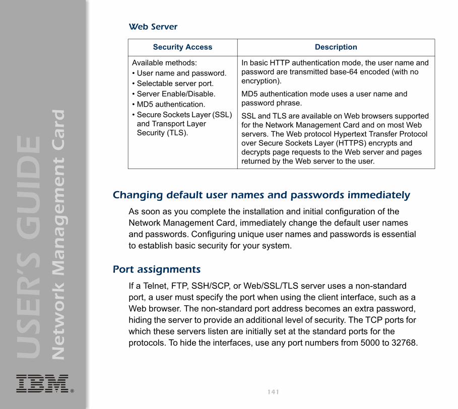
®
USE
R’S
GU
IDE
Netw
ork
Man
ag
em
en
t C
ard
Web Server
Changing default user names and passwords immediately
As soon as you complete the installation and initial configuration of the Network Management Card, immediately change the default user names and passwords. Configuring unique user names and passwords is essential to establish basic security for your system.
Port assignments
If a Telnet, FTP, SSH/SCP, or Web/SSL/TLS server uses a non-standard port, a user must specify the port when using the client interface, such as a Web browser. The non-standard port address becomes an extra password, hiding the server to provide an additional level of security. The TCP ports for which these servers listen are initially set at the standard ports for the protocols. To hide the interfaces, use any port numbers from 5000 to 32768.
Security Access Description
Available methods:• User name and password.• Selectable server port.• Server Enable/Disable.• MD5 authentication.• Secure Sockets Layer (SSL)
and Transport Layer Security (TLS).
In basic HTTP authentication mode, the user name and password are transmitted base-64 encoded (with no encryption).
MD5 authentication mode uses a user name and password phrase.
SSL and TLS are available on Web browsers supported for the Network Management Card and on most Web servers. The Web protocol Hypertext Transfer Protocol over Secure Sockets Layer (HTTPS) encrypts and decrypts page requests to the Web server and pages returned by the Web server to the user.
141

®
USE
R’S
GU
IDE
Netw
ork
Man
ag
em
en
t C
ard
User names, passwords, community names (SNMP)
All user names, passwords, and community names for SNMP are transferred over the network as plain text. A user who is capable of monitoring the network traffic can determine the user names and passwords required to log on to the accounts of the control console or Web interface of the Network Management Card. If your network requires the higher security of the encryption-based options available for the control console and Web interface, be sure to disable SNMP access or set its access to read-only. (Read-only access allows you to receive status information and to use SNMP traps.)
142

®
USE
R’S
GU
IDE
Netw
ork
Man
ag
em
en
t C
ard
Authentication
Authentication vs. Encryption
You can select to use security features for the Network Management Card that control access by providing basic authentication through user names, passwords, and IP addresses, without using encryption. These basic security features are sufficient for most environments in which sensitive data are not being transferred.
For a security method that provides additional authentication for the Web interface, but does not provide the higher security of encryption, use Message Digest 5 (MD5) Authentication.
To ensure that data and communication between the Network Management Card and the client interfaces, such as the control console and the Web interface, cannot be intercepted, you can provide a greater level of security by using one or more of the following encryption-based methods:
• For the Web interface, use the Secure Sockets Layer (SSL) and Transport Layer Security (TLS) protocols. You can also use these protocols in combination with MD5 authentication.
• To encrypt user names and passwords for control console access, use the Secure SHell (SSH) protocol.
• To encrypt user names, passwords, and data for the secure transfer of files, use the Secure CoPy (SCP) protocol.
See "MD5 authentication (for the Web interface)" on page 144.
For more information on these protocols for encryption-based security, see "Secure SHell (SSH) and Secure CoPy (SCP)" on page 146 and "Secure Sockets Layer (SSL)/Transport Layer Security (TLS)" on page 147.
143

®
USE
R’S
GU
IDE
Netw
ork
Man
ag
em
en
t C
ard
MD5 authentication (for the Web interface)
The Web interface option for MD5 authentication enables a higher level of access security than the basic HTTP authentication scheme. The MD5 scheme is similar to CHAP and PAP remote access protocols. Enabling MD5 implements the following security features:
• The Web server requests a user name and a password phrase (distinct from the password). The user name and password phrase are not transmitted over the network, as they are in basic authentication. Instead, a Java login applet combines the user name, password phrase, and a unique session challenge number to calculate an MD5 hash number. Only the hash number is returned to the server to verify that the user has the correct login information; MD5 authentication does not reveal the login information.
• In addition to the login authentication, each form post for configuration or control operations is authenticated with a unique challenge and hash response.
• After the authentication login, subsequent page access is restricted by IP addresses and a hidden session cookie. (You must have cookies enabled in your browser.) Pages are transmitted in their plain-text form, with no encryption.
If you use MD5 authentication for the Web interface, be sure to increase the security for other interfaces to the Network Management Card.
• Control console: Use SSH (which disables Telnet) for encrypted access.
• File transfer: Disable FTP, and instead use SCP, which encrypts user names, passwords, and files.
• SNMP: Disable SNMP or disable its write access. With read-only access, trap facilities remain available.
144

®
USE
R’S
GU
IDE
Netw
ork
Man
ag
em
en
t C
ard
For additional information on MD5 authentication, see RFC document #1321 at http://www.ietf.org, the Web site of the Internet Engineering Task Force. For CHAP, see RFC document #1994.
You can use MD5 and the encryption-based SSL/TSL security protocols together. See "Secure Sockets Layer (SSL)/Transport Layer Security (TLS)" on page 147 for an example of the extra security benefits of using both.
145

®
USE
R’S
GU
IDE
Netw
ork
Man
ag
em
en
t C
ard
Encryption
Secure SHell (SSH) and Secure CoPy (SCP)
The Secure SHell (SSH) protocol provides a secure mechanism to access computer consoles or shells remotely. The protocol authenticates the server (in this case, the Network Management Card) and encrypts all transmissions between the SSH client and the server:
• SSH is an alternative to Telnet, which does not provide encryption.• SSH protects the username and password, the credentials for
authentication, from being used by anyone intercepting network traffic.• To authenticate the SSH server (the Network Management Card) to the
SSH client, SSH uses a host key that is unique to the SSH server and that provides an identification that cannot be falsified. Therefore, an invalid server on the network cannot obtain a user name and password from a user by presenting itself as a valid server.
• The Network Management Card supports versions 1 and 2 of SSH. The encryption mechanisms of the versions differ, and each version has advantages. Version 1 provides faster login to the Network Management Card, and version 2 provides improved protection from attempts to intercept, forge or change data that are transmitted.
• When you enable SSH, Telnet is automatically disabled.• The interface, user accounts, and user access rights are the same
whether you access the control console through SSH or Telnet.
To create a host key, see "Create an SSH Host Key" on page 170.
For information on supported SSH client applications, see "Telnet/SSH" on page 43.
146

®
USE
R’S
GU
IDE
Netw
ork
Man
ag
em
en
t C
ard
Secure CoPy (SCP) is a secure file transfer application that you can use instead of FTP. SCP uses the SSH protocol as the underlying transport protocol for encryption of user names, passwords, and files:
• When you enable and configure SSH, you automatically enable and configure SCP. No further configuration of SCP is needed.
• You must explicitly disable FTP. It is not disabled by enabling SSH.
Secure Sockets Layer (SSL)/Transport Layer Security (TLS)
For secure Web communication, you enable Secure Sockets Layer (SSL) and Transport Layer Security (TLS) by selecting HTTPS (SSL/TLS) as the protocol mode to use for access to the Web interface of the Network Management Card. Hypertext Transfer Protocol over Secure Sockets Layer (HTTPS) is a Web protocol that encrypts and decrypts page requests from the user and pages that are returned by the Web server to the user. Originally developed by Netscape, it has become an internet standard supported by most Web browsers.
The Network Management Card supports SSL version 3.0 and TLS version 1.0. Most browsers let you select the version of SSL to enable.
When SSL is enabled, your browser displays the lock icon, usually at the bottom of the screen.
SSL uses a digital certificate to enable the browser to authenticate the server (in this case, the Network Management Card). The browser verifies the following:
• The format of the server certificate is correct.• The expiration date and time for the server certificate has not passed.• The DNS name or IP address specified when a user logs on matches
the common name in the server certificate.• The server certificate is signed by a trusted certifying authority.
147
®
USE
R’S
GU
IDE
Netw
ork
Man
ag
em
en
t C
ard
Each major browser manufacturer distributes CA root certificates of the commercial Certificate Authorities in the certificate store (cache) of its browser so that it can compare the signature on the server certificate to the signature on a CA root certificate.
You can use the Security Wizard, provided on the Network Management Card CD, to create a certificate signing request to an external Certificate Authority, or if you do not want to use an existing Certificate Authority, you can create a root certificate to upload to the certificate store (cache) of a browser. You can also use the Wizard to create a server certificate to upload to the Network Management Card.
SSL also uses various algorithms and encryption ciphers to authenticate the server, encrypt data, and ensure the integrity of the data (for example, that it has not been intercepted and sent by another server).
You can use SSL/TLS and MD5 authentication together to provide the security benefits of both. MD5 authentication does not provide encryption, but its authentication methods can be a useful enhancement to the security provided by SSL/TLS.
See "Creating and Installing Digital Certificates" on page 150 for a summary of how these certificates are used.
To create certificates and certificate requests, see "Create a Root Certificate & Server Certificates" on page 161 and "Create a Server Certificate and Signing Request" on page 166.
See "CipherSuite" on page 58 to select which authentication and encryption algorithms to use.
148

®
USE
R’S
GU
IDE
Netw
ork
Man
ag
em
en
t C
ard
NoteWeb browsers cache (save) Web pages that you recently accessed and enable you to return to those pages without re-entering your user name and password. MD5 authentication, however, requires you to enter your user name and password even to access a cached Web page, for example, when you use the Back button of Microsoft Internet Explorer. Therefore, if you are using the SSL and TLS protocols without also using MD5 authentication, always close your browser session before you leave your computer unattended.
149

®
USE
R’S
GU
IDE
Netw
ork
Man
ag
em
en
t C
ard
Creating and Installing Digital Certificates
Purpose
For network communication that requires a higher level of security than password encryption, the Web interface of the Network Management Card supports the use of digital certificates with the Secure Sockets Layer (SSL) protocol. Digital certificates can authenticate the Network Management Card (the server) to the Web browser (the SSL client).
The sections that follow summarize the three methods of creating, implementing, and using digital certificates. Read these sections to determine the most appropriate method for your system:
• "Method 1: Use the auto-generated default certificate of the Network Management Card" on page 151.
• "Method 2: Use the Security Wizard to create a CA certificate and a server certificate" on page 153.
• "Method 3: Use the Security Wizard to create a certificate-signing request to be signed by the root certificate of an external Certificate Authority and to create a server certificate" on page 155.
.
Note
You can also use Method 3 if your company or agency operates its own Certificate Authority. Use the Security Wizard the same way, but use your own Certificate Authority in place of a commercial Certificate Authority.
150

®
USE
R’S
GU
IDE
Netw
ork
Man
ag
em
en
t C
ard
Choosing a method for your system
Using the Secure Sockets Layer (SSL) protocol, you can choose any of the following methods for using digital certificates.
Method 1: Use the auto-generated default certificate of the Network Management Card. When you enable SSL, you must restart the Network Management Card. While restarting, if no server certificate exists on the Network Management Card, the Network Management Card generates a default server certificate that is self-signed but that you cannot configure.
This method has the following advantages and disadvantages:• Advantages:
– Before they are transmitted, the user name and password for Network Management Card access and all data to and from the Network Management Card are encrypted.
– You can use this default server certificate to provide encryption-based security while you are setting up either of the other two digital certificate options, or you can continue to use it for the benefits of encryption that SSL provides.
• Disadvantages: – The Network Management Card takes up to 5 minutes to create this
certificate, and the Web interface is not available during that time. (This delay occurs the first time you log on after you enable SSL.)
– This method does not include the browser-based authentication provided by a CA certificate (a certificate signed by a Certificate Authority) as Methods 2 and 3 provide. There is no CA Certificate cached in the browser. Therefore, whenever you log on to the Network Management Card, the browser generates a security alert, indicating that a certificate signed by a trusted authority is not available and asking if you want to proceed.
151
®
USE
R’S
GU
IDE
Netw
ork
Man
ag
em
en
t C
ard
– The default server certificate on the Network Management Card has the serial number of the Network Management Card in place of a valid common name (the DNS name or the IP address of the Network Management Card). Therefore, although the Network Management Card can control access to its Web interface by user name, password, and account type (for example, Administrator, Device Manager, or Read-Only User), the browser cannot verify what Network Management Card is sending or receiving data.
– The length of the public key (RSA key) that is used for encryption when setting up an SSL session is only 768 bits. (The public key used in Methods 2 and 3 is 1024 bits, providing more complex encryption and consequently a higher level of security.)
152

®
USE
R’S
GU
IDE
Netw
ork
Man
ag
em
en
t C
ard
Method 2: Use the Security Wizard to create a CA certificate and a server certificate. You use the Security Wizard to create two digital certificates:
• A CA root certificate (Certificate Authority root certificate) that the Security Wizard uses to sign all server certificates and which you then install into the certificate store (cache) of the browser of each user who needs access to the Network Management Card.
• A server certificate that you upload to the Network Management Card. When the Security Wizard creates a server certificate, it uses the CA root certificate to sign the server certificate.
The Web browser authenticates the Network Management Card sending or requesting data:
• To identify the Network Management Card, the browser uses the common name (IP address or DNS name of the Network Management Card) that was specified in the distinguished name of the server certificate when the certificate was created.
• To confirm that the server certificate is signed by a trusted signing authority, the browser compares the signature of the server certificate with the signature in the root certificate cached in the browser. An expiration date confirms whether the server certificate is current.
This method has the following advantages and disadvantages.• Advantages:
– Before they are transmitted, the user name and password for Network Management Card access and all data to and from the Network Management Card are encrypted.
– The length of the public key (RSA key) that is used for encryption when setting up an SSL session is 1024 bits, providing more complex encryption and consequently a higher level of security than
153
®
USE
R’S
GU
IDE
Netw
ork
Man
ag
em
en
t C
ard
the public key used in Method 1. (This longer encryption key is also used in Method 3.)
– The server certificate that you upload to the Network Management Card enables SSL to verify that data are being received from and sent to the correct Network Management Card. This provides an extra level of security beyond the encryption of the user name, password, and transmitted data.
– The root certificate that you install to the browser enables the browser to authenticate the server certificate of the Network Management Card to provide additional protection from unauthorized access.
• Disadvantage: Because the certificates do not have the digital signature of a commercial Certificate Authority, you must load a root certificate individually into the certificate store (cache) of each user’s browser. (Browser manufacturers already provide root certificates for commercial Certificate Authorities in the certificate store within the browser. See Method 3.)
154

®
USE
R’S
GU
IDE
Netw
ork
Man
ag
em
en
t C
ard
Method 3: Use the Security Wizard to create a certificate-signing request to be signed by the root certificate of an external Certificate Authority and to create a server certificate. You use the Security Wizard to create a request (a .csr file) to send to a Certificate Authority. The Certificate Authority returns a signed certificate (a .crt file) based on information you submitted in your request. You then use the Security Wizard to create a server certificate (a .p15 file) that includes the signature from the root certificate returned by the Certificate Authority. You upload the server certificate to the Network Management Card.
This method has the following advantages and disadvantages.• Advantages:
– Before they are transmitted, the user name and password for Network Management Card access and all data to and from the Network Management Card are encrypted.
– You have the benefit of authentication by a Certificate Authority that already has a signed root certificate in the certificate cache of the browser. (The CA certificates of commercial Certificate Authorities are distributed as part of the browser software, and a Certificate Authority of your own company or agency has probably already loaded its CA certificate to the browser store of each user’s browser.) Therefore, you do not have to upload a root certificate to the browser of each user who needs access to the Network Management Card.
– The length of the public key (RSA key) that is used for setting up an SSL session is 1024 bits, providing more complex encryption and
Note
You can also use Method 3 if your company or agency operates its own Certificate Authority. Use the Security Wizard the same way, but use your own Certificate Authority in place of a commercial Certificate Authority.
155

®
USE
R’S
GU
IDE
Netw
ork
Man
ag
em
en
t C
ard
consequently a higher level of security than the public key used in Method 1 (This longer encryption key is also used in Method 2.)
– The server certificate that you upload to the Network Management Card enables SSL to verify that data are being received from and sent to the correct Network Management Card. This provides an extra level of security beyond the encryption of the user name, password, and transmitted data.
– The browser matches the digital signature on the server certificate that you uploaded to the Network Management Card with the signature on the CA root certificate that is already in the certificate cache of the browser to provide additional protection from unauthorized access.
• Disadvantages: – Setup requires the extra step of requesting a signed root certificate
from a Certificate Authority.– An external Certificate Authority may charge a fee for providing
signed certificates.
156

®
USE
R’S
GU
IDE
Netw
ork
Man
ag
em
en
t C
ard
Firewalls
Although some methods of authentication provide a higher level of security than others, complete protection from security breaches is almost impossible to achieve. Well-configured firewalls are an essential element in an overall security scheme.157
®
USE
R’S
GU
IDE
Netw
ork
Man
ag
em
en
t C
ard
Using the Security Wizard
Overview
Authentication
Authentication verifies the identity of a user or a network device (such as a Network Management Card). Passwords typically identify computer users. However, for transactions or communications requiring more stringent security methods on the Internet, the Network Management Card supports more secure methods of authentication:
• Secure Sockets Layer (SSL), used for secure Web access, uses digital certificates for authentication. A digital CA root certificate is issued by a Certificate Authority (CA) as part of a public key infrastructure, and its digital signature must match the digital signature on a server certificate on the Network Management Card.
• Secure SHell (SSH), used for remote terminal access to the control console of the Network Management Card, uses a public host key for authentication rather than a digital certificate.
How certificates are used. Most Web browsers, including all browsers supported by the Network Management Card, contain a set of CA root certificates from all of the commercial Certificate Authorities.
158

®
USE
R’S
GU
IDE
Netw
ork
Man
ag
em
en
t C
ard
Authentication of the server (in this case, the Network Management Card) occurs each time a connection is made from the browser to the server. The browser checks to be sure that the certificate of the server is signed by a Certificate Authority known to the browser. For this authentication to occur:
• Each Network Management Card with SSL enabled must have a server certificate on the Network Management Card itself.
• Any browser that is used to access the Web interface of the Network Management Card must contain the CA root certificate that signed the server certificate.
If authentication fails, the browser prompts you on whether to continue despite the fact that it cannot authenticate the server.
If your network does not require the authentication provided by digital certificates, you can use the default certificate that the Network Management Card generates automatically. The digital signature of the default certificate will not be recognized by browsers, but a default certificate enables you to use SSL for the encryption of transmitted user names, passwords, and data. (If you use the default certificate, the browser prompts you to agree to unauthenticated access before it logs you on to the Web interface of the Network Management Card.)
How SSH host keys are used. An SSH host key authenticates the identity of the server (the Network Management Card) each time an SSH client contacts the Network Management Card. Each Network Management Card with SSH enabled must have an SSH host key on the Network Management Card itself.
159

®
USE
R’S
GU
IDE
Netw
ork
Man
ag
em
en
t C
ard
Files you create for SSL and SSH securityUse the Security Wizard to create the following components of an SSL and SSH security system:
• The server certificate for the Network Management Card, if you want the benefits of authentication that such a certificate provides.You can create either of the following types of server certificate:– A server certificate signed by a custom CA root certificate also created
with the Security Wizard. Use this method if your company or agency does not have its own Certificate Authority and you do not want to use an external Certificate Authority to sign the server certificate.
– A server certificate signed by an external Certificate Authority. This Certificate Authority can be one that is managed by your own company or agency or can be one of the commercial Certificate Authorities whose CA root certificates are distributed as part of the software of a browser.
• A certificate signing request containing all the information required for a server certificate except the digital signature. You need this request if you are using an external Certificate Authority:
• A CA root certificate.• An SSH host key that your SSH client program uses to authenticate the
Network Management Card when you log on to the control console interface.
Server certificates, host keys, and CA root certificates created by the Security Wizard will not work with products such as OpenSSL and Microsoft Internet Information Server (ISS).
Note
All public keys for SSL certificates and all host keys for SSH that are created with the Security Wizard are 1024-bit RSA keys. If you do not create and use SSL server certificates and SSH host keys with the Security Wizard, the Network Management Card generates 768-bit RSA keys.
160
®
USE
R’S
GU
IDE
Netw
ork
Man
ag
em
en
t C
ard
Create a Root Certificate & Server Certificates
Summary
Use this procedure if your company or agency does not have its own Certificate Authority and you do not want to use a commercial Certificate Authority to sign your server certificates:
• Create a CA root certificate that will be used to sign all server certificates to be used with Network Management Cards. During this task, two files are created:– The file with the .p15 extension is an encrypted file that contains the
private key and public root certificate of the Certificate Authority. This file signs the server certificates.
– The file with the .crt extension, which contains only the public root certificate of the Certificate Authority. You load this file into each Web browser that will be used to access the Network Management Card so that the browser can validate the server certificate of the Network Management Card.
• Create a server certificate, which is stored in a file with a .p15 extension. During this task, you are prompted for the CA root certificate that signs the server certificate.
• Load the server certificate onto the Network Management Card.• For each Network Management Card that requires a server certificate,
repeat the tasks that create and load the server certificate.
Note
The public RSA key that is part of a certificate generated by the Security Wizard is 1024 bits. (The default key generated by the Network Management Card, if you do not use the Wizard, is 768 bits.)
161

®
USE
R’S
GU
IDE
Netw
ork
Man
ag
em
en
t C
ard
The procedure
Create the CA root certificate. Perform these steps: (Click Next to move from screen to screen.)
1. If the Security Wizard is not already installed on your computer, install it by running the installation program APC Security Wizard.exe from the Network Management Card CD.
2. On the Windows Start menu, select Programs, then APC Security Wizard, to start the Wizard program.
3. On the screen labeled Step 1, select CA Root Certificate as the type of file to create.
4. Enter a name for the file that will contain the public root certificate and private key of the Certificate Authority. The file name must have a .p15 extension. By default, the file will be created in the installation folderC:\Program Files\American Power Conversion\APC Security Wizard.
5. On the screen labeled Step 2, provide the information to configure the CA root certificate. The Country and Common Name fields are required; the other fields are optional. For the Common Name field, enter an identifying name of your company or agency; use only alphanumeric characters, with no spaces.
6. On the next screen, review the summary of the certificate. Scroll down to view the unique serial number and fingerprints of the certificate. To make any changes to the information you provided, click Back, and revise the information.
Note
By default, a CA root certificate is valid for 10 years from the current date and time, but you can edit the Validity Period Start and Validity Period End fields.
NoteThe subject information and the issuer information of the certificate should be identical.
162
®
USE
R’S
GU
IDE
Netw
ork
Man
ag
em
en
t C
ard
7. The last screen verifies that the certificate has been created and instructs you on the next tasks:– This screen displays the location and name of the .p15 file that you
will use to sign the server certificates.– This screen also displays the location and name of the .crt file,
which is the CA root certificate that you will load into the browser of each user who needs to access the Network Management Card.
Load the CA root certificate to your browser. Load the .crt file to the browser of each user who needs to access the Network Management Card.
Following is a summary of the procedure for Microsoft Internet Explorer:1. Select Tools, then Internet Options from the menu bar.2. On the Content tab in the Internet Options dialog box, click
Certificates and then Import.3. The Certificate Import Wizard will guide you through the rest of the
procedure. The file type to select is X.509, and the CA Public Root Certificate is the .crt file created in the procedure "Create a Root Certificate & Server Certificates" on page 161.
See the help system of the browser for information on how to load the .crt file into the certificate store (cache) of the browser.
163
®
USE
R’S
GU
IDE
Netw
ork
Man
ag
em
en
t C
ard
Create an SSL Server User Certificate. Perform these steps: (Click Next to move from screen to screen.)
1. On the Windows Start menu, select Programs, then APC Security Wizard, to start the Wizard program.
2. On the screen labeled Step 1, select SSL Server Certificate as the type of file to create.
3. Enter a name for the file that will contain the server certificate and the private key. The file name must have a .p15 extension. By default, the file will be created in the installation folderC:\Program Files\American Power Conversion\APC Security Wizard.
4. Click the Browse button, and select the CA root certificate created in the procedure "Create a Root Certificate & Server Certificates" on page 161. The CA Root Certificate is used to sign the Server User Certificate being generated.
5. On the screen labeled Step 2, provide the information to configure the server certificate. The Country and Common Name fields are required; the other fields are optional. For the Common Name field, enter the IP address or DNS name of the server (Network Management Card). Because the configuration information is part of the signature, it cannot be exactly the same as the information you provided when creating the CA root certificate; the information you provide in some of the fields must be different.
6. On the next screen, review the summary of the certificate. Scroll down to view the unique serial number and fingerprints of the certificate To make any changes to the information you provided, click Back, and revise the information.
Note
By default, a server certificate is valid for 10 years from the current date and time, but you can edit the Validity Period Start and Validity Period End fields.
164
®
USE
R’S
GU
IDE
Netw
ork
Man
ag
em
en
t C
ard
7. The last screen verifies that the certificate has been created and instructs you on the next task, to load the server certificate to the Network Management Card. It displays the location and name of the Server Certificate, which has a .p15 file extension and contains the Network Management Card private key and public root certificate.
Load the server certificate to the Network Management Card
Perform these steps:1. On the Network menu of the Web interface of the Network
Management Card, select the Web/SSL option.2. In the SSL/TLS Server Certificate section of the page, browse to the server
certificate, the .p15 file you created in the procedure "Create a Root Certificate & Server Certificates" on page 161. The default is C:\Program Files\American Power Conversion\APC Security Wizard.
Note
The information for every certificate must be unique. The configuration of a server certificate cannot be the same as the configuration of the CA root certificate. (The expiration date is not considered part of the unique configuration; some other configuration information must also differ.)
NoteAlternatively, you can use FTP or Secure CoPy (SCP) to transfer the server certificate to the Network Management Card. If you use FTP or SCP for the transfer, you must specify the \sec directory on the Network Management Card. For SCP, the command to transfer a certificate named cert.p15 to a Network Management Card with an IP address of 156.205.6.185 would be:
scp cert.p15 [email protected]:\sec\cert.p15
165

®
USE
R’S
GU
IDE
Netw
ork
Man
ag
em
en
t C
ard
Create a Server Certificate and Signing Request
Summary
Use this procedure if your company or agency has its own Certificate Authority or if you plan to use a commercial Certificate Authority to sign your server certificates:
• Create a Certificate Signing Request (CSR). The CSR contains all the information for a server certificate except the digital signature. This process creates two output files: – The file with the .p15 extension contains the private key of the
Network Management Card. – The file with the .csr extension contains the certificate signing
request, which you send to an external Certificate Authority.• When you receive the signed certificate from the Certificate Authority,
import that certificate. Importing the certificate combines the .p15 file containing the private key and the file containing the signed certificate from the external Certificate Authority. The output file is a new encrypted server certificate file with a .p15 extension.
• Load the server certificate onto the Network Management Card.• For each Network Management Card that requires a server certificate,
repeat the tasks that create and load the server certificate.
The procedure
Create the Certificate Signing Request (CSR). Perform these steps: (Click Next to move from screen to screen.)
1. If the Security Wizard is not already installed on your computer, install it by running the installation program APC Security Wizard.exe from the Network Management Card CD.
166

®
USE
R’S
GU
IDE
Netw
ork
Man
ag
em
en
t C
ard
2. On the Windows Start menu, select Programs, then APC Security Wizard, to start the Wizard program.
3. On the screen labeled Step 1, select Certificate Request as the type of file to create.
4. Enter a name for the file that will contain the private key of the Network Management Card. The file name must have a .p15 extension. By default, the file will be created in the installation folderC:\Program Files\American Power Conversion\APC Security Wizard.
5. On the screen labeled Step 2, provide the information to configure the certificate signing request (CSR) with the information that you want the signed server certificate to contain. The Country and Common Name fields are required; the other fields are optional. For the Common Name field, enter the IP Address or DNS name of the Network Management Card.
6. On the next screen, review the summary of the certificate. Scroll down to view the unique serial number and fingerprints of the certificate. To make any changes to the information you provided, click Back, and revise the information.
7. The last screen verifies that the certificate signing request has been created and displays the location and name of the file, which has a .csr extension.
NoteBy default, a server certificate is valid for 10 years from the current date and time, but you can edit the Validity Period Start and Validity Period End fields.
NoteThe subject information and the issuer information of the certificate should be identical.
167
®
USE
R’S
GU
IDE
Netw
ork
Man
ag
em
en
t C
ard
8. Send the certificate signing request to an external Certificate Authority, either a commercial Certificate Authority or, if applicable, a Certificate Authority managed by your own company or agency.
Import the signed certificate. When the external Certificate Authority returns the signed certificate, perform these steps to import the certificate. This procedure combines the signed certificate and the private key into an SSL server certificate that you then upload to the Network Management Card. (Click Next to move from screen to screen.)
1. On the Windows Start menu, select Programs, then APC Security Wizard, to start the Wizard program.
2. On the screen labeled Step 1, select Import Signed Certificate.3. Browse to and select the signed server certificate that you received
from the external Certificate Authority. The file has a .cer or .crt extension.
4. Browse to and select the file you created in step 4 of the task, "Create the Certificate Signing Request (CSR)" on page 166. This file has a .p15 extension, contains the private key of the Network Management Card, and, by default, is located in the installation folderC:\Program Files\American Power Conversion\APC Security Wizard.
5. Specify a name for the output file that will be the signed server certificate that you upload to the Network Management Card. The file must have a .p15 extension.
6. Click Next to generate the server certificate. The Issuer Information of the certificate, on the summary screen, confirms that the external Certificate Authority signed the certificate.
See the instructions provided by the Certificate Authority regarding the signing and issuing of server certificates.
168

®
USE
R’S
GU
IDE
Netw
ork
Man
ag
em
en
t C
ard
7. The last screen verifies that the certificate has been created and instructs you on the next task, to load the server certificate to the Network Management Card. It displays the location and name of the server certificate, which has a .p15 file extension and contains the private key of the Network Management Card and the public key obtained from the .cer or .crt file.
Load the server certificate to the Network Management Card
Perform these steps:1. On the Network menu of the Web interface of the Network
Management Card, select the Web/SSL option.2. In the SSL/TLS Server Certificate section of the page, browse to the server
certificate, the .p15 file you created in the procedure "Import the signed certificate" on page 168. The default location isC:\Program Files\American Power Conversion\APC Security Wizard.
NoteAlternatively, you can use FTP or Secure CoPy (SCP) to transfer the server certificate to the Network Management Card. If you use FTP or SCP for the transfer, you must specify the \sec directory on the Network Management Card. For SCP, the command to transfer a certificate named cert.p15 to a Network Management Card with an IP address of 156.205.6.185 would be:
scp cert.p15 [email protected]:\sec\cert.p15
169

®
USE
R’S
GU
IDE
Netw
ork
Man
ag
em
en
t C
ard
Create an SSH Host Key
Summary
This procedure is optional. If you select SSH encryption, but do not create a host key, the Network Management Card generates a 768-bit RSA key when it restarts. Host keys for SSH that are created with the Security Wizard are 1024-bit RSA keys:
• Use the Security Wizard to create a host key, which is encrypted and stored in a file with .p15 extension.
• Load the host key onto the Network Management Card.
The procedure
Create the host key. Perform these steps. (Click Next to move from screen to screen.)
1. If the Security Wizard is not already installed on your computer, install it by running the installation program APC Security Wizard.exe from the Network Management Card CD.
2. On the Windows Start menu, select Programs, then APC Security Wizard, to start the Wizard program.
3. On the screen labeled Step 1, select SSH Server Host Key as the type of file to create.
4. Enter a name for the file that will contain the host key. The name must have a .p15 extension. By default, the file will be created in the installation folder C:\Program Files\American Power Conversion\APC Security Wizard.
5. Click Next to generate the host key.6. The summary screen displays the SSH version 1 and version 2
fingerprints, which are unique for each host key and identify the host key. After you load the host key onto the Network Management Card, you can verify that the correct host key was uploaded by verifying that
170
®
USE
R’S
GU
IDE
Netw
ork
Man
ag
em
en
t C
ard
the fingerprints displayed here match the SSH fingerprints on the Network Management Card, as displayed by your SSH client program.
7. The last screen verifies that the host key has been created and instructs you on the next task, to load the host key to the Network Management Card. It displays the location and name of the host key, which has a .p15 file extension.
Load the host key to the Network Management Card. Perform these steps:
1. On the Network menu of the Web interface of the Network Management Card, select the Telnet/SSH option.
2. In the SSH User Host Key File section of the page, browse to the host key, the .p15 file you created in the procedure "Create the host key" on page 170. (The default location isC:\Program Files\American Power Conversion\APC Security Wizard.)
3. On the SSH Host Key Fingerprint section of the page, note the fingerprint for the version (or versions) of SSH you are using. Then log on to the Network Management Card through your SSH client program, and verify that the correct host key was uploaded by verifying that these fingerprints match the fingerprints that the client program displays.
NoteAlternatively, you can use FTP or Secure CoPy (SCP) to transfer the host key file to the Network Management Card. If you use FTP or SCP for the transfer, you must specify the \sec directory, on the Network Management Card. For SCP, the command to transfer a host key named hostkey.p15 to a Network Management Card with an IP address of 156.205.6.185 would be:
scp cert.p15 [email protected]:\sec\hostkey.p15
171

®
USE
R’S
GU
IDE
Netw
ork
Man
ag
em
en
t C
ard
Troubleshooting
Network Management Card
Network Management Card access problems
Problem Solution
Unable to ping the Network Management Card
If the Status LED of the Network Management Card is green, try to ping another node on the same network segment as the Network Management Card. If that fails, it is not a problem with the Network Management Card. If the Status LED is not green, or if the ping test succeeds, perform the following checks:• Verify all network connections.• Verify the IP addresses of the Network Management Card
and the NMS.• If the NMS is on a different physical network (or
subnetwork) from the Network Management Card, verify the IP address of the default gateway (or router).
• Verify the number of subnet bits for the subnet mask of the Network Management Card.
The terminal program cannot allocate the communications port when you try to configure the Network Management Card
Before you can use a terminal to configure the Network Management Card, you must shut down any application, service, or program using the communications port.
Cannot access the control console through a serial connection
Make sure that you did not change the baud rate. Try 2400, 9600, 19200, or 38400.
172

®
USE
R’S
GU
IDE
Netw
ork
Man
ag
em
en
t C
ard
Cannot access the control console remotely
• Make sure you are using the correct access method (Telnet or SSH). An Administrator can enable these access methods through the Telnet/SSH option of the Network menu. By default, Telnet is enabled. Enabling SSH automatically disables Telnet.
• For Secure SHell (SSH), the Network Management Card may be creating a host key. The Network Management Card can take up to 5 minutes to create this host key, and SSH is not accessible during that time.
Cannot access the Web interface
• Verify that HTTP or HTTPS access is enabled.• Make sure you are specifying the correct URL, one that is
consistent with the security system used by the Network Management Card. SSL requires https, not http, at the beginning of the URL.
• Verify that you can ping the adapter.• Verify that you are using a Web browser that is supported
for the Network Management Card. See "Supported Web Browsers" on page 24.
• If the Network Management Card has just restarted and SSL security is being set up, the Network Management Card may be generating a server certificate. The Network Management Card can take up to 5 minutes to create this certificate, and the SSL/TLS server is not available during that time.
Problem Solution
173

®
USE
R’S
GU
IDE
Netw
ork
Man
ag
em
en
t C
ard
174
SNMP issues
The following table describes known SNMP problems:
Synchronization problems
Problem Solution
Unable to perform a GET • Verify the read (GET) community name.• Use the control console or Web interface to ensure that
the NMS has access. See "SNMP" on page 50.
Unable to perform a SET • Verify the read/write (SET) community name.• Use the control console or Web interface to ensure that
the NMS has write (SET) access. See "SNMP" on page 50.
Unable to receive traps at the NMS
Query the mconfigTrapReceiverTable MIB OID to verify that the NMS IP address is listed correctly, and the community name defined for the NMS matches the community name in the table. If either is not correct, use SETs to the mconfigTrapReceiverTable OIDs, or use the control console or Web interface to correct the trap receiver definition. See "SNMP" on page 50.
Traps received at an NMS are not identified
See your NMS documentation to verify that the traps are properly integrated in the alarm/trap database.
Problem Solution
A Synchronized Control Group member does not participate in a synchronized action.
Make sure the status of the group member is set to Enabled. Also check the battery capacity of the group member, if the synchronized action required uninterruptible power supplies to turn on.
An attempt to add a member to a Synchronized control group fails.
The Multicast IP Address, Synchronized Control Group Number, and firmware version must match those of other members of the group.

®
USE
R’S
GU
IDE
Netw
ork
Man
ag
em
en
t C
ard
How to Export Configuration Settings
Retrieving and Exporting the .ini file
Summary of the procedure
An Administrator can retrieve a dynamically generated .ini file of the current configuration of one Network Management Card and export that file to another Network Management Card or to multiple Network Management Cards:
1. Configure a Network Management Card to have the settings you want to export.
2. Retrieve the .ini file from that Network Management Card.3. Customize the .ini file (to change at least the TCP/IP settings) and
make a copy to export.4. Use any of the file transfer protocols supported by the Network
Management Card to transfer the copied file to one or more additional Network Management Cards. (To transfer the file to multiple Network Management Cards simultaneously, write an FTP or SCP script that repeats the steps for transferring the file to a single Network Management Card.)
5. Each receiving Network Management Card stores the file temporarily in its flash memory, uses it to reconfigure its own Network Management Card settings, and then deletes the file.
175

®
USE
R’S
GU
IDE
Netw
ork
Man
ag
em
en
t C
ard
Contents of the .ini file
The config.ini file that you retrieve from a Network Management Card contains the following:
• Section headings, which are category names enclosed in brackets ([ ]), and under each section heading, keywords, which are labels describing specific Network Management Card settings.
• Each keyword is followed by an equals sign and the current value that is set for that parameter, either the default value (if the value has not been specifically configured) or the configured value:– The Override keyword, with its default value, prevents one or more
keywords and their device-specific values from being exported:• In the [NetworkTCP/IP] section, the default value for Override (the
MAC address of the Network Management Card) blocks the exporting of the values for the keywords SystemIP, SubnetMask, DefaultGateway, and BootMode.
• In the UPS section, the default value for Override (the serial number of the uninterruptible power supply) blocks the exporting of the value for the RatedOutputVoltage keyword. (RatedOutputVoltage and its value are included in the .ini file only if the output voltage of the uninterruptible power supply is configurable.)
– You must edit the section [SystemDate/Time] if you want to set the system date and time of a receiving Network Management Card or cause that Network Management Card to use an NTP Server to set its date and time.
NoteOnly section headings and keywords supported for the specific device associated with the Network Management Card from which you retrieve the file are included.
See "Customizing" on page 178 for configuration guidelines for date and time settings.
176

®
USE
R’S
GU
IDE
Netw
ork
Man
ag
em
en
t C
ard
Detailed procedures
Use the following procedures to retrieve the settings of one Network Management Card and export them to one or more other Network Management Cards.
Retrieving. To set up and retrieve an .ini file to export:1. Configure a Network Management Card with the settings you want to
export.
2. Use FTP to retrieve the file config.ini from the Network Management Card you configured:a. Open a connection to the Network Management Card, using its IP
Address. For example:ftp> open 158.165.2.132
b. Log on, using the Administrator user name and password configured for the Network Management Card.
c. Retrieve the config.ini file containing the current settings of the Network Management Card:ftp> get config.ini
The file is written to the folder from which you launched FTP.
NoteTo avoid errors, configure the Network Management Card by using its Web interface or control console whenever possible. Directly editing the .ini file risks introducing errors.
To create batch files and use a utility to retrieve configuration settings from multiple Network Management Cards and export them to other Network Management Cards, see Release Notes: ini File Utility, version 1.0 on the Network Management Card CD.
177

®
USE
R’S
GU
IDE
Netw
ork
Man
ag
em
en
t C
ard
Customizing. You must customize the file to change at least the TCP/IP settings before you export it:
1. Use a text editor to customize the file: – Section headings, keywords, and pre-defined values are not case-
sensitive, but string values that you define are case-sensitive.– Use adjacent quotation marks to indicate no value. For example,
LinkURL1="" indicates that the URL is intentionally undefined.– To define values, opening and closing quotation marks are optional,
except to enclose values that contain leading or trailing spaces or values which are already enclosed in quotation marks. (Leading or trailing spaces not within the opening and closing quotation marks are ignored.)
– To export a specific system date and time or any scheduled events, you must configure the values directly in the .ini file.• To export a specific system time, export only the configured
[SystemDate/Time] section as a separate .ini file. (The time necessary to export a large file would cause the configured time to be significantly inaccurate.)
• For greater accuracy, if the Network Management Cards receiving the file can access a Network Time Protocol (NTP) Server, set the value for the NTPEnable keyword as follows:
NTPEnable=enabled
– Add comments about changes that you made. The first printable character of a comment line must be a semicolon (;).
2. Copy the customized file to another file name in the same folder:– The copy, which you will export to other Network Management Cards,
can have any name up to 64 characters and must have the .ini file suffix.– Retain the original customized file for future use. The file that you
retain is the only record of your comments. They are removed automatically from the file that you export.
178

®
USE
R’S
GU
IDE
Netw
ork
Man
ag
em
en
t C
ard
Exporting the file to a single Network Management Card. To export the .ini file to another Network Management Card, use any of the file transfer protocols supported by Network Management Cards (including FTP, FTP Client, SCP, and TFTP). The following example uses FTP:
1. From the folder containing the customized .ini file and its copy, use FTP to log in to the Network Management Card to which you are exporting the .ini file. For example:ftp> open 158.165.4.135
2. Export the copy of the customized .ini file. The receiving Network Management Card accepts any file name that has the .ini suffix, is no more than 64 characters in length, and is exported to its root directory:ftp> put filename.ini
Exporting the file to multiple Network Management Cards. To export the .ini file to multiple Network Management Cards:
• Use FTP or SCP, but write a script that incorporates and repeats the steps used for exporting the file to a single Network Management Card.
• Use a batch processing file and the .ini file utility.
To create the batch file and use the utility, see Release Notes: ini File Utility, version 1.0 on the Network Management Card CD.
179

®
USE
R’S
GU
IDE
Netw
ork
Man
ag
em
en
t C
ard
The Upload Event and its Error Messages
The event and its error messages
The following system event occurs when the receiving Network Management Card completes using the .ini file to update its settings:
Configuration file upload complete, with number valid values
This event has no default severity level.
If a keyword, section name, or value is invalid, the event text is extended to include notification of the following errors:
NoteThe export to, and the subsequent upload by, the receiving Network Management Card succeeds even if there are errors.
Event text Description
Configuration file warning: Invalid keyword on line number.
Configuration file warning: Invalid value on line number.
A line with an invalid keyword or value is ignored.
Configuration file warning: Invalid section on line number.
If a section name is invalid, all keyword/value pairs in that section are ignored.
Configuration file warning: Keyword found outside of a section on line number.
A keyword entered at the beginning of the file (before any section headings) is ignored.
Configuration file warning: Configuration file exceeds maximum size.
If the file is too large, the Network Management Card stores and processes what it can, but ignores what it cannot. Reduce the size of the file, or divide it into two files, and try uploading again.
180
®
USE
R’S
GU
IDE
Netw
ork
Man
ag
em
en
t C
ard
Messages in config.ini
A device associated with the Network Management Card from which you download the config.ini file must be discovered successfully in order for its configuration to be included. If the device (such as an uninterruptible power supply) is not present or, for some other reason, is not discovered, the config.ini file contains a message under the appropriate section name, instead of keywords and values. For example:
UPS not discovered
If you did not intend to export the configuration of the device as part of the .ini file import, ignore these messages.
Errors generated by overridden values
The Override keyword and its value will generate error messages in the event log when it blocks the exporting of values.
The overridden values are device-specific and not appropriate to export to other Network Management Cards. Therefore, you can ignore these error messages. To prevent these error messages from occurring, you can delete the lines that contain the Override keyword and the lines that contain the values that they override. Do not delete or change the line containing the section heading.
See "Contents of the .ini file" on page 176 for information about which values are overridden.
181

®
USE
R’S
GU
IDE
Netw
ork
Man
ag
em
en
t C
ard
Using the Device IP Configuration Wizard
On Windows operating systems, instead of using the preceding procedure for exporting .ini files, you can choose to update Network Management Card settings by using the Device IP Configuration Wizard.For a detailed description of how to update the configuration settings of one or more Network Management Card using the Device IP Configuration Wizard, see "Device IP Configuration Wizard" on page 183.
182

®
USE
R’S
GU
IDE
Netw
ork
Man
ag
em
en
t C
ard
Device IP Configuration Wizard
Purpose and Requirements
Purpose: configure basic TCP/IP settings
You can use the Device IP Configuration Wizard to configure the basic TCP/IP settings (IP address, subnet mask, and default gateway) of Network Management Cards in either of the following ways:
• Automatically discover and configure unconfigured Network Management Cards remotely over your TCP/IP network.
• Configure or reconfigure a Network Management Card through a direct connection from the serial port of your computer to the uninterruptible power supply that contains the Network Management Card.
System requirements
The Wizard runs on Windows NT®, Windows 2000, Windows 2003, and Windows XP Intel-based workstations.
Note
The Wizard can discover and configure Network Management Cards only if they are on the same network segment as the computer that is running the Wizard.
183

®
USE
R’S
GU
IDE
Netw
ork
Man
ag
em
en
t C
ard
Install the Wizard
Automated installation
If autorun is enabled on your CD-ROM drive, the installation program starts automatically when you insert the Network Management Card CD.
Manual installation
If autorun is not enabled on your CD-ROM drive, run setup.exe in the Wizard directory on the Network Management Card CD, and follow the on-screen instructions.
184
®
USE
R’S
GU
IDE
Netw
ork
Man
ag
em
en
t C
ard
Use the Wizard
Launch the Wizard
The installation creates a shortcut link in the Start menu that you can use to launch the Wizard.
Configure the basic TCP/IP settings remotely
Prepare to configure the settings. Before you run the Wizard, be sure that you have the information you will need during the configuration procedure:
1. Contact your network administrator to obtain valid TCP/IP settings to use.
2. If you are configuring multiple unconfigured Network Management Cards, obtain the MAC address of each one so that you can identify each Network Management Card that the Wizard discovers. (The Wizard displays the MAC address for a discovered Network Management Card on the same screen on which you then enter the TCP/IP settings.)The MAC address is on a label on the uninterruptible power supply containing the Network Management Card and on the Quality Assurance slip that came with the uninterruptible power supply.
Run the Wizard to perform the configuration. To discover and configure, over the network, Network Management Cards that are not configured:
1. From the Start menu, launch the Wizard. The Wizard automatically detects the first Network Management Card that is not configured.
2. Select Remotely (over the network), and click Next >.3. Enter the TCP/IP settings (System IP, Subnet Mask, and Default
Gateway) for the unconfigured Network Management Card identified by the MAC address at the top of the screen. Then click Next >.
185
®
USE
R’S
GU
IDE
Netw
ork
Man
ag
em
en
t C
ard
4. On the Transmit Current Settings Remotely screen, if you check-mark Start a Web browser when finished, the default Web browser connects to the Network Management Card after you transmit the settings of the Network Management Card.
5. Click Finish to transmit the TCP/IP settings. If the IP address you entered is in use on the network, the Wizard prompts you to enter an IP address that is not in use. Enter a correct IP address, and click Finish.
6. The Wizard searches for another unconfigured Network Management Card. If it finds one, it displays the screen with data entry boxes for the TCP/IP settings of that Network Management Card:– To skip configuring the Network Management Card whose MAC
address is currently displayed, click Cancel.– To configure the TCP/IP settings of the next Network Management
Card, repeat this procedure beginning at step 3.
186
®
USE
R’S
GU
IDE
Netw
ork
Man
ag
em
en
t C
ard
Configure or reconfigure the TCP/IP settings locally
To configure a single Network Management Card through a serial connection:1. Contact your network administrator to obtain valid TCP/IP settings.2. Connect the serial configuration cable that came with the
uninterruptible power supply that contains the Network Management Card.a. Connect one end to an available communications port on your
computer. Make sure no other application is using the port.b. Connect the other end to the serial port of the uninterruptible power
supply.3. From the Start menu, launch the Wizard application:
– If the Network Management Card is not configured, wait for the Wizard to detect it.
– If you are assigning basic TCP/IP settings serially to the Network Management Card, click Next> to move to the next screen.
4. Select Locally (through the serial port), and click Next >.5. Enter the TCP/IP settings (System IP, Subnet Mask, and Default
Gateway) for the Network Management Card. Then click Next >.6. On the Transmit Current Settings Remotely screen, if you check-mark
Start a Web browser when finished, the default Web browser connects to the Network Management Card after you transmit the Network Management Card settings.
7. Click Finish to transmit the TCP/IP settings. If the IP address you entered is in use on the network, the Wizard prompts you to enter an IP address that is not in use. Enter a correct IP address, and click Finish.
8. If you selected Start a Web browser when finished in step 6, you can now configure other parameters through the Web interface of the Network Management Card.
187

®
USE
R’S
GU
IDE
Netw
ork
Man
ag
em
en
t C
ard
File Transfers
Introduction
OverviewThe Network Management Card automatically recognizes binary firmware files. Each of these files contains a header and one or more Cyclical Redundancy Checks (CRCs) to ensure that the data contained in the file is not corrupted before or during the transfer operation.
When new firmware is transmitted to the Network Management Card, the program code is updated and new features become available.
This chapter describes how to transfer firmware files to Network Management Cards.
To transfer a firmware file to the Network Management Card, see "Upgrading Firmware" on page 189.
To verify a file transfer, see "Verifying Upgrades and Updates" on page 196.
188

®
USE
R’S
GU
IDE
Netw
ork
Man
ag
em
en
t C
ard
Upgrading Firmware
Firmware defined
Broadly defined, firmware is highly specialized, reliable software that resides on a memory chip within a computer or computer-related device.
Firmware files (Network Management Card)
The operating system (AOS) and application module files used with the Network Management Card share the same basic format:
apc_hw0x_type_version.bin
• hw0x: Identifies the version of the Network Management Card that will run this binary file.
• type: Identifies whether the file is for the operating system (AOS) or the application module (APP) for the Network Management Card.
• version: The version number of the application file. For example, a code of 253 would indicate version 2.5.3.
• bin: Indicates that this is a binary file.
189

®
USE
R’S
GU
IDE
Netw
ork
Man
ag
em
en
t C
ard
Firmware file transfer methods
To upgrade the firmware of a Network Management Card on a Microsoft Windows operating system, use the firmware upgrade tool, a self-extracting executable file available at no cost from the IBM Web site (http://www.ibm.com).
On a Linux operating system, you must upgrade the two firmware modules (the AOS module and the APP module) separately. The separate firmware modules are also available on the IBM Web site. After you download them, use one of the following upgrade methods:
• Use FTP or SCP to upgrade the firmware of one or more Network Management Cards over the network.
• Use XMODEM to upgrade the firmware for a Network Management Card that is not on the network.
When you use FTP, SCP, or XMODEM to upgrade the firmware for a Network Management Card, the operating system (AOS) module must be transferred to the Network Management Card before you transfer the application (APP) module.
For more information about the firmware modules, see "Firmware files (Network Management Card)" on page 189.
190
®
USE
R’S
GU
IDE
Netw
ork
Man
ag
em
en
t C
ard
Use FTP or SCP to upgrade one Network Management Card
For you to be able to use FTP to upgrade a single Network Management Card over the network:
• The Network Management Card must be connected to the network.• The FTP server must be enabled at the Network Management Card.• The Network Management Card must have its TCP/IP settings
(System IP, Subnet Mask, and Default Gateway addresses) configured.
To use FTP to upgrade the Network Management Card:1. Open an MS-DOS command prompt window on a computer that is
connected to the network. Go to the directory that contains the firmware upgrade files, and list the files. For the directory C:\apc, use the following commands:C:\>cd\apcC:\apc>dir
Files listed for the Network Management Card, for example, might be the following:– apc_hw02_aos_253.bin – apc_hw02_app_253.bin
2. Open an FTP client session:C:\apc>ftp
3. Type open and the IP address of the Network Management Card, and press Enter. If the Port setting for FTP Server in the Network menu has changed from its default value of 21, you must use the non-default value in the FTP command:a. For some FTP clients, use a colon to add the port number to the end
of the IP address.
191

®
USE
R’S
GU
IDE
Netw
ork
Man
ag
em
en
t C
ard
b. For Windows FTP clients, separate the port number from the IP address by a space. For example, if the FTP Server Port setting of the Network Management Card has been changed from its default of 21, such as to 21000, you would use the following command for a Windows FTP client transferring a file to a Network Management Card with an IP address of 150.250.6.10:ftp> open 150.250.6.10 21000
4. Log on using the Administrator user name and password. (apc is the default for both.)
5. Upgrade the AOS. For example:ftp> binftp> put apc_hw02_aos_253.bin
6. When FTP confirms the transfer, type quit to close the session.7. Wait 20 seconds, and then repeat this procedure for the application
module. In step 5, use the application module file instead of the AOS module.
192

®
USE
R’S
GU
IDE
Netw
ork
Man
ag
em
en
t C
ard
To use Secure CoPy (SCP) to upgrade the firmware for one Network Management Card:
1. Identify and locate the firmware modules described in the preceding instructions for FTP.
2. Use an SCP command line to transfer the AOS firmware module to the Network Management Card. The following example assumes the Network Management Card IP address of 158.205.6.185 and an AOS module apc_hw02_aos_253.bin.scp apc_hw02_aos_253.bin [email protected]:apc_hw02_aos_253.bin
3. Use a similar SCP command line, with the name of the application module instead of the AOS module, to transfer the application module to the Network Management Card.
193

®
USE
R’S
GU
IDE
Netw
ork
Man
ag
em
en
t C
ard
Use FTP or SCP to upgrade multiple Network Management Cards
To upgrade multiple Network Management Cards using an FTP client or using SCP, write a script which automatically performs the appropriate procedure described "Use FTP or SCP to upgrade one Network Management Card" on page 191.
Use XMODEM to upgrade one Network Management Card
To use XMODEM to upgrade the firmware for a single Network Management Card that is not on the network:
1. Select a serial port at the local computer and disable any service which uses that port.
2. Connect the smart-signaling cable that came with the Network Management Card to the selected port and to the serial port at the uninterruptible power supply that contains the Network Management Card.
3. Run a terminal program (such as HyperTerminal), configure the selected port for 9600 bps, 8 data bits, no parity, 1 stop bit, and no flow control, and save the changes.
4. Press Enter to display the User Name prompt.5. Enter your Administrator user name and password. The default for
both is apc.6. Start an XMODEM transfer:
a. Select option 3—System.b. Select option 4—File Transfer.c. Select option 2—XMODEM.d. Type Yes at the prompt to continue with the transfer.
194

®
USE
R’S
GU
IDE
Netw
ork
Man
ag
em
en
t C
ard
7. Select the appropriate baud rate. A higher baud rate causes faster firmware upgrades. Also, change the terminal program’s baud rate to match the one selected, and press Enter.
8. From the terminal program’s menu, select the binary AOS file to transfer via XMODEM-CRC. After the XMODEM transfer is complete, set the baud rate to 9600. The Network Management Card will automatically restart.
9. Repeat step 3 through step 8 to install the application module. In step 8, substitute the application module file name for the AOS module file name.
For information about the format used for application modules, see "Firmware files (Network Management Card)" on page 189.
195

®
USE
R’S
GU
IDE
Netw
ork
Man
ag
em
en
t C
ard
Verifying Upgrades and Updates
Overview
To verify that the firmware upgrade was successful, see the Last Transfer Result message, available through the FTP Server option of the Network menu (in the control console only), or use an SNMP GET to the mfiletransferStatusLastTransferResult OID.
Last Transfer Result codes
You can also verify the versions of the upgraded operating system (AOS) and application modules by using the About System option in the System menu of the control console or in the Help menu of the Web interface, or by using an SNMP GET to the MIB II sysDescr OID.
Code Description
Successful The file transfer was successful.
Result not available There are no recorded file transfers.
Failure unknown The last file transfer failed for an unknown reason.
Server inaccessible The TFTP or FTP server could not be found on the network.
Server access denied The TFTP or FTP server denied access.
File not found The TFTP or FTP server could not locate the requested file.
File type unknown The file was downloaded but the contents were not recognized.
File corrupt The file was downloaded but at least one CRC was bad.
196

®
USE
R’S
GU
IDE
Netw
ork
Man
ag
em
en
t C
ard
Index
Numerics9-pin connector 7
A
About System 32Access
Access Type setting for SNMP 50FTP Server 42limiting NMS SNMP access by IP address 50locally to the control console 12priority for logging on 4remotely to the control console 11security options for each interface 139troubleshooting 173
Actions option, Events menu 115Add Client IP, PowerChute Network
Shutdown 91Advanced settings, TCP/IP 38AOS firmware module 32Apparent Load Power, Output Power
Status 75Application firmware module 32Apply Local Computer Time 65Audible Alarm setting 89Authentication
as a User Manager setting 64MD5 143Phrase (User Manager setting) 64SNMP Traps 119with SSL 147
Authentication Traps setting 119Auto Logout (User Manager setting 64
B
Battery settings for capacity, current,and voltage 76
BB
B
BB
BB
C
CC
C
C
1
attery Voltage 76oot mode
process 130settings 37
OOTPAfter IP Assignment setting 133Boot mode settings 37Communication settings 39DHCP & BOOTP boot process 131Remain in DHCP & BOOTP
mode setting 133Status LED indicating BOOTP requests 8
OOTP Only boot mode setting 37rowsers
CA certificates in thestore (cache) of the browser 148
supported Web browsers 24ypass Lower Voltage setting 87ypass Upper Voltage setting 87
alibration, date and result 76ertificates
choosing which method to use 150creating and installing for SSL 150deleting 67methods
Security Wizard creates allcertificates 153
Use a Certificate Authority (CA) 155Use the default certificate 151
ipherSuiteChoosing SSL encryption ciphers and hash
algorithms 58purpose of the algorithms and ciphers 148
lient ID setting 39, 133
97

®
USE
R’S
GU
IDE
Netw
ork
Man
ag
em
en
t C
ard
Community Namefor trap receivers 119SNMP 50verifying correctness 174
config.ini file, contents 176Configuration menu
Battery 88General Settings 89option in uninterruptible power supply
menu 87Configure Synchronized Control 100Configured Client IP Addresses parameter,
PowerChute Network Shutdown 91Configuring
MD5 authentication 144SSH 43SSL/TLS 55
Contact identification (whom to contact) 65Contact settings (environmental) 105Contact status (environmental) 104Control console
Device Manager menu 21External and Internal Environmental Monitor
Settings options 102main screen 15navigating menus 20refreshing menus 20
Control menu, control console options 83Customizing user configuration files 178
D
Data logconfiguration 129importing into spreadsheet 112Log Interval setting 129using FTP or SCP to retrieve 112
Data menu 128Date & Time settings 65Delete SSH Host Keys and SSL
Certificates 67
19
Detailed Status optionuninterruptible power supply menu 73
Device IP Configuration Wizardusing to configure required TCP/IP
settings 185using to update
configuration settings 182Device Manager menu 71
control console 21DHCP
After IP Assignment setting 133APC cookie 136Boot mode settings 37Communication settings 39Configuration 130Cookie Is setting 133, 134DHCP & BOOTP boot process 131Network Management Card settings 131Remain in DHCP & BOOTP
mode setting 133Require vendor specific cookie to accept
DHCP Address setting 133, 134response options 135Retry Then Stop setting 134Status LED indication for making DHCP
requests 8DHCP & BOOTP boot mode setting 37DHCP Only boot mode setting 37Diagnostics option, uninterruptible power
supply menu 77Disabling
e-mail to a recipient 124event logging 116Reverse DNS Lookup 40sending any traps to an NMS 119sending authentication traps to an NMS 119synchronized group membership 100
Domain Name setting 38, 133Domain names
configuring 38, 133
8

®
USE
R’S
GU
IDE
Netw
ork
Man
ag
em
en
t C
ard
of trap receivers 119overriding expansion of
host name to domain name 38
E
E-mailconfiguring 120configuring recipients 123Email action 117Email option, Events menu 123Email Recipients
Local (SMTP Server) recommendedsetting 124
menu option 123enabled by default for severe events 117enabling and disabling 124message format (long or short) 125reason to use local DNS server 121setting up an account for the
Network Management Card 124using for paging 124
Email Recipients 123Enabling
e-mail forwarding to external SMTPservers 124
e-mail to a recipient 124MD5 authentication 143Reverse DNS Lookup 40sending any traps to an NMS 119sending authentication traps to an NMS 119SSH 45Synchronized Group Membership 100Telnet 45
Encryptionwith SSH and SCP 146with SSL 55
Environmental monitorcontact settings 105contact status 104control console status report 103probe settings 105
19
probe status 104Settings options in the control console 102status icons in the Web interface 29Web interface status report 103
Error messages 26for firmware file transfer 196from overridden values during
.ini file transfer 181Event log 116
accessing 20deleting by typing d in control console 111disabling 116errors from overridden values during
.ini file transfer 181using Ctrl+L to display the log in
control console 111using FTP del command 114using FTP or SCP to retrieve 112
event.txt filecontents 112importing into spreadsheet 112
Events menuActions 115Email (Web interface) 117Email Recipients (Web interface) 123Event log 116Log option 110SNMP traps 117Syslog action 117
External Batteries setting 89
F
Facility (Syslog setting) 52Fingerprints, displaying and comparing 44Firewall, as essential to security 157Firmware
benefits of upgrading 189file transfer methods 190
FTP or SCP 191XMODEM 194
files for Network Management Card 189
9

®
USE
R’S
GU
IDE
Netw
ork
Man
ag
em
en
t C
ard
200
upgrading 189verifying upgrades and updates 196versions displayed on main screen 16
Format, Email Recipients 125Frequency (Output Power Status) 75From Address (SMTP setting) 122FTP 42
disabling when SCP is used 42using to retrieve text version of event or data
log 112
G
General Settingsconfiguration (uninterruptible power supply
menu) 89Generation setting, Email Recipients 124GET commands, troubleshooting 174GMT Offset (TIme Zone) 66
H
HelpAbout System option (Web interface) 32on control console 20
Host keyscreating 170deleting 67file name and status 48fingerprints
displaying for versions 1 and 2 49generated by the Network Management
Card 44transferring to the
Network Management Card 44, 48Host Name, configuring 38, 133HTTP
port 57protocol mode 56
HTTPSport 57protocol mode 56
Hyperlinks, defining 69
I
Identification 65displaying on main screen 16MIB-II variables 65
Informational (event severity) 116ini files, See User configuration filesInput
Frequency 74Voltage 74
Integrated Environmental Monitor 7connections on Network Management Card
face-plate 6output relay connection pins 7output relay settings 106output relay status 104zone 1 and 2 (input contact) connector
pins 7IP addresses
for PowerChute Network Shutdownclients 91
of DNS server for e-mail 120of trap receivers 119to limit access to specified NMSs 50
K
Keywordsuser configuration file 176
L
Last Battery Replacement setting 89Links
redirecting links on the Links menu 33, 69Load Current and Load Power,
Output Power Status 75Local SMTP Server 124Location (system value) 65Lock icon indicating SSL is enabled 56Logging on
DNS name or IP address matched tocommon name 25

®
USE
R’S
GU
IDE
Netw
ork
Man
ag
em
en
t C
ard
201
error messages for Web interface 26Web interface 25
Login date and timecontrol console 16Web interface 28
Low-Battery Duration 88
M
Main screeninformation fields displayed 16status fields displayed 17
Manual boot mode setting 37Manual option to set date and time 65Map to Syslog’s Priorities 53Maximum Line Voltage, Utility Voltage
Status 74Maximum Shutdown Time, PowerChute
Network Shutdown 88Maximum Shutdown Time setting 91negotiation 92
MD5enabling 143how it performs authentication 144requirement of login credentials to access
cached Web page 149Menus
Configuration 87, 88Control 80Control Console 19Data 31, 128Device Manager 71event-related 31Events 31, 107Help 32Links 33, 69Network 31, 34System 32, 62uninterruptible power supply 31, 71, 87
MIB-II Identification variables 65Minimum Line Voltage, Utility Power
Status 74
Multicast IP Address 101
N
Name of Scheduled Shutdown 96Network Management Card
port assignment 141preventing restart for inactivity 9troubleshooting
access problems 172Network menu
Email (control console) 123FTP Server 42Ping utility 41SNMP 50Syslog 52TCP/IP 36Telnet/SSH 43WAP 61Web/SSL 55
Network Time Protocol (NTP) 66NMS IP/Domain Name setting 50NMS receiving unidentified trap,
troubleshooting 174NTP 66
O
On Retry Failure setting 39Operating Frequency field (control
console) 74, 75Operating System (AOS) firmware
module 32Output Power Status fields 75Output relay
as Network Management Card feature 1connections on Network Management Card
face-plate 6control console status report 104pins on 9-pin connector 7settings 106Web interface status report 104

®
USE
R’S
GU
IDE
Netw
ork
Man
ag
em
en
t C
ard
Output Voltage (Utility Line settings) 87Override keyword, in user configuration
file 176
P
Pagingby using e-mail 124
Passwordschange immediately for security 141default for Administrator, Device Manager,
and Read Only User 25for NMS that is a trap receiver 119Password setting in
User Manager option 64recovering from lost password 13using non-standards ports as extra
passwords 141Ping utility
for troubleshooting Network Management Card access 172
for troubleshooting Network Management Card network connection 41
Port (Syslog setting) 52Port Speed setting 38, 133Ports
assigning 141default
for FTP Server 42for HTTP 57for HTTPS 57for SSH 46for Telnet 46
using a non-default portfor FTP 42for HTTP 57for HTTPS 57for SSH 46for Telnet 46
Power Synchronized Delay 81, 100PowerChute Network Shutdown
Maximum Shutdown Time negotiation 92
20
parameters 91Primary NTP Server 66Probes
settings 105status 104
Protocol Modeselecting for control console access 45selecting for Web access 56
Put UPS To Sleep 85Put UPS To Sleep Gracefully 86
R
Read access by an NMS 50Receiver NMS IP/Domain Name,
for trap receivers 119Recipient’s SMTP Server 124Reset Only TCP/IP to Defaults 67Reset to Defaults 67Reset to Defaults Except TCP/IP 67Restart
Reboot Management Interface 67Reboot UPS 84Reboot UPS Gracefully 85
Retry Then Fail setting 39Retry Then Stop setting (DHCP) 134Return Battery Capacity 88Return Battery Capacity Offset 101Return Delay 88Reverse DNS Lookup 40Root certificates, creating 161RSA key exchange algorithm 58Runtime Remaining 76
S
Schedulingshutdowns of uninterruptible power supplies
in a Synchronized Control Group 97uninterruptible power supply self-tests 79uninterruptible power supply shutdowns 94
2

®
USE
R’S
GU
IDE
Netw
ork
Man
ag
em
en
t C
ard
SCPenabled and configured with SSH 43, 147using to retrieve text version of event or data
log 112Secondary NTP Server 66Section headings, user configuration
file 176Secure CoPy. See SCP.Secure Hash Algorithm (SHA) 58Secure SHell. See SSH.Secure Sockets Layer
See SSL.Security
authenticationauthentication vs. encryption 143through digital certificates with SSL 147with MD5 144
certificate-signing requests 148disabling less secure interfaces 144, 147encryption with SSH and SCP 146how certificates are used 158How SSH host keys are used 159immediately changing username and
password 141options for each interface 139planning and implementing 139, 143SCP as alternative to FTP 147SSL
choosing a method to use certificates 150CipherSuite algorithms and ciphers 148
supported SSH clients 43using MD5 authentication 144using non-standards ports as extra
passwords 141Security Wizard
creating certificateswithout a Certificate Authority 161
creating server certificatesto use with a Certificate Authority 166
creating signing requests 166creating SSH host keys 170
20
Self-Test (of uninterruptible power supply)performing 78Result and Date 76scheduling 89
Send DNS Query 40Sensitivity setting 87Server certificates
creating to use with a Certificate Authority 166
creating without a Certificate Authority 161Server IP/Domain Name (Syslog setting) 52SET commands, troubleshooting 174Set Manually (date and time) 65Severe (event severity) 116Severity levels (of Events) 116Shutdown Behavior parameter, PowerChute
Network Shutdown 91Shutdown Delay parameter 88Shutdown Parameters, Configuration
option of uninterruptible power supply menu 88
ShutdownsHow to edit, disable, or delete 98how to schedule 94how to schedule synchronized 97
Signal servers 83Signing requests
creating 166Simple Signal Shutdowns setting 89Simulate Power Failure 78Sleep Time 88SMTP Server setting 122SNMP
Access Type setting 50Authentication Traps 119Community Name setting 50enabling and disabling 50NMS IP/Domain Name setting 50SNMP traps option 117
3

®
USE
R’S
GU
IDE
Netw
ork
Man
ag
em
en
t C
ard
troubleshooting problems 174SSH
configuring 43enabling 43encryption 146fingerprints, displaying and comparing 44host key
as identifier that cannot be falsified 146creating 170file name and status 48transferring to the Network Management
Card 44modifying the Port setting 46, 57obtaining an SSH client 43server configuration 47v1 and v2 Encryption Algorithms 47
SSLauthentication through digital
certificates 147certificate signing requests 148encryption ciphers and hash algorithms 58
Start/Stop Runtime Calibration 78Status
icons in the Web interface 29in Web interface 28on control console main screen 17summary 27uninterruptible power supply
in detail 73summary 73
Sync ControlConfigure Synchronized Control 100Sync Control Group Status 99
Synchronize with NTP Server,(Date & Time) 66
Synchronized Control Groupsactions
LED behavior during 82Turn UPS Off with shutdown delay. 82
configurable parameters 100defining membership
and group number 100
20initiating a synchronized action. 80Power Synchronized Delay 81the synchronization process 81troubleshooting 174
Syslogenabled by default for all events 117enabling and disabling 52Events menu option 117mapping event severity to
Syslog priorities 53settings 52test 54
Systeminformation, obtaining 32Name 65
System menu 62About System option (control console) 32Date & Time 65Identification 65Tools 67User Manager 64
System: Warmstart and System: Coldstart events 92
T
TCP/IPAdvanced settings 38Boot mode 37Client ID setting 39, 133Current settings fields 36default gateway 36, 37defining settings for the Network
Management Card 36Domain Name setting 38, 133Host Name setting 38, 133On Retry Failure setting 39Port Speed setting 38, 133restoring default settings 67Retry Then Fail setting 39setting port assignments for extra
security 141
4

®
USE
R’S
GU
IDE
Netw
ork
Man
ag
em
en
t C
ard
205
subnet mask 36, 37system IP address 36, 37User Class setting 39, 133Vendor Class setting 39, 133
Telnet/SSHAccess option 45host key
displaying fingerprints 49file name and status 48
option in Network menu 43selecting the protocol mode 45SSH Port option 46SSHv1 and v2 Encryption Algorithms 47Telnet Port option 46
Test UPS Alarm 78Testing the network connection to the DNS
server 40To Address, Email Recipients 124Tools menu 67
File Transfer 68initiating an action 67
Transport Layer Security (TLS) 147Trap Generation 119Trap Receivers 119Traps
troubleshooting unidentified traps 174Troubleshooting
e-mail configuration 121Network Management Card
access problems 172problems logging on to Web interface 25SNMP problems 174Synchronized Control Groups 174verification checklist 172
Turn UPS Off Gracefully, for oneuninterruptible power supply orSynchronized Control Group 83
Turn UPS off, for one uninterruptible power supply or Synchronized Control Group 83
Turn UPS On, for one uninterruptible power supply or Synchronized Control Group 83
U
Unidentified traps, troubleshooting 174Uninterruptible power supply menu 71
Configuration 87Detailed Status 73Diagnostics option 77General Settings (configuration) 89Shutdown Parameters 88Status 73
Up Timecontrol console main screen 16Web interface 28
Update Interval, Date & Timesetting 66
Upgrading firmwarewithout using a utility 189
UPS Name setting 89"UPS not discovered" message 181UPS Position setting 89URL address formats 26Use SMTP Server, Email Recipients 124User access identification,
control console interface 16User accounts, types 5User Class setting 39, 133User configuration files
contents 176customizing 178exporting system time separately 178messages for undiscovered devices 181overriding device-specific values 176retrieving and exporting 175system event and error messages 180using the .ini file utility to
retrieve and transfer the files 177User Manager option, to configure
access 64User Name
change immediately for security 141

®
USE
R’S
GU
IDE
Netw
ork
Man
ag
em
en
t C
ard
default for Administrator, Device Manager, and Read Only User 25
User Manager setting 64Utility Voltage Status
Input Frequency 74Input Voltage 74
V
Vendor Class setting 39, 133
W
WAP 61Warning (event severity) 116Web interface 23
enable or disable protocols 56logging on 25logon error messages 26modifying the Port setting
for FTP 42for HTTP 57for HTTPS 57for SSH 46for Telnet 46
status 28summary page 27troubleshooting access problems 173Up Time 28URL address formats 26
Wireless Application Protocol (WAP) 61
X
XMODEM 68
20
6
®
USE
R’S
GU
IDE
Netw
ork
Man
ag
em
en
t C
ard
Edition notice © Copyright International Business Machines Corporation, 2004. All rights reserved.
U.S. Government Users – Documentation related to restricted rights – Use, duplication or disclosure is subject to restrictions set forth in GSA ADP Schedule Contract with IBM Corp.
TrademarksIBM is a trademark of International Business Machines Corporation in the United States, other countries, or both.
Microsoft, Windows, and Windows NT are trademarks of Microsoft Corporation in the United States, other countries, or both.
UNIX is a registered trademark of The Open Group in the United State and other countries.
Java and all Java-based trademarks and logos are trademarks of Sun Microsystems, Inc. in the United States, other counties, or both.
Linux is a trademak of Linus Torvalds in the United States, other countries, or both.
APC, the APC logo, InfraStruXure, Matrix-UPS, PowerChute, PowerNet, and Smart-UPS are trademarks of American Power Conversion Corporation.
Other company, product, or service names may be the trademarks or service marks of others.
Part Number: 25R5648
207