user’s manual and installation guide - cncdrive · pinout of the of the drive’s encoder idc-16...
TRANSCRIPT

BLSV-05020 AC Servo drive
User’s Manual and Installation Guide
Contents
1. Safety, policy and warranty.
1.1. Safety notes. 1.2. Policy. 1.3. Warranty.
2. Electric specifications. 2.1.Operation ranges.
3. Connections and pinouts. 3.1. Connectors. 3.1.1. Motor and encoder connectors. 3.1.2. Main,USB & Power in connectors.
4. Indicators and faults. 4.1. LED indicators. 4.2. Fault Conditions and Error Handling.
5. Installation guide.
5.1. Installation of drive frame. 5.2. Motor wiring. 5.3. Encoder Wiring. 5.4. Shielding Techniques. 5.5. Error Line Wiring. 5.6. Reset line wiring. 5.7. Mixing the Reset and Error lines.
6. Power Supply – selection and filtering.
7. Troubleshooting.

1. Safety, policy and warranty. 1.1. Safety Notes
Please read through this documentation before operating the device. The devices can operate on low DC bus Voltages only and can withstand Voltage spikes upto 63Volts. Never connect higher than 50V DC bus Voltage to the drive, because it causing a permanent damage to the device. Moving objects, like machine axis can be hazardous, avoid touching and keep distance from mechanic moving parts of the machine while the motor power supply is on and connected to the drives. The device should not be used where it can cause personal injury, death or high financial loss. Never open the drive’s chassis and never touch inner circuitry even if it’s unpowered. Take care of power supply’s correct polarity connection, wrong polarity connection of the Motor Power supply will cause permanent damage to the device. Never disconnect the motor from the drive when power supply is connected to the drive and is under Voltage. Do not short the motor output terminals, it may cause permanent damage to the device. The drives are in enclosure, but this metal case is not meant to protect the drive from dust and falling chips, liquid or other moisture material. Please take care to protect the drives from taint damage. 1.2. Policy CNCdrive cannot take responsibility for any personal injury and/or financial loss caused by their drives’ failure or caused by following an error in this documentation. 1.3. Warranty
We give 12 months of standard warranty period with our BLSV-05020 drives. Customers may send back the drives within 15 days from reception date if they are not satisfied with the performance. Using the drive outside of the specified electrical ranges may cause permanent damage to the device and voids warranty. Opening the drive’s metal frame and making any modification in it voids warranty.

2. Electric specifications and limitations. 2.1.Operation ranges
Property Min Typ Max Unit Notes
Motor supply voltage
12 - 50 VDC Optimal U=rated+5..10% >63V is destructive!
Motor current
0
-
20
A
Limited by drive at software set threshold, maximum at 20A
Logic supply voltage 11.5 12 14 VDC >20VDC input Voltage may cause permanent damage to the device!
Logic supply current 150 200 250 mA
Operating temperature 0
65 °C Automatic shutdown at 65°C
Opto-isolator input Voltage
3
-
-
V
Use external series resistor in case of input Voltage>5VDC For 12V input use 1kOhm For 24V input use 2.2kOhm
Opto-isolator current 3 5 10 mA
Step input frequency 0
400 kHz
Direction signal stabile state minimum allowed valid time after step signal active edge
1
1
1
usec
Step signal active and inactive edges can be configured in software by user.
Encoder maximum frequency 1 1 1 MHz With 4x decoding
Error line output current 0 - 10 mA 20mA continiously output current is destructive
Switching frequency 20 20 20 kHz
PID loop sampling time 1
65535 *60usec User setable in 60usec steps
Minimum allowed motor coil resistance
0.5
-
-
Ohm
If resistance is lower it should be extended with inductor or with resistor/resistor wire.
Minimum allowed motor coil’s inductance
500
-
-
uH
If inductance of the motor coil is lower, it should be extended with series coil for correct operation.

1. Connections and pinouts. 3.1. Connectors 3.1.1. Motor and encoder connectors
Figure 1. Motor and encoder connectors
Description of the Motor connector: Connect the 3 phase AC servo motor to the U V and W connectors of the drive. Description of the encoder connector:
Connect the encoder and hall sensors to the IDC-16 input jack pins. The pinout of this connector is listed below. The connection can be made the following ways:
1.) Connect with an IDC-16 ribbon female connector crimped onto a 15 wire ribbon cable, the other end of this cable may be a DSUB-15 female connector on the control box's frontpanel.
2.) The drive comes with a 20cm long IDC-16 to DSUB-15 female connectors crimped cable. Connect a DSUB-15 male connector to this female connector and solder the signal wires to this male connector.

Pinout of the of the drive’s encoder IDC-16 connector to our BL60 series motor’s encoder wires colors.
Pin number
Signal in the drive’s IDC-16 male encoder connector
Our BL60 series motor’s encoder wire colors
1. NC (No internal connection)
2. Encoder signal B- Grey/white 3. Encoder signal B+ Grey
4. Encoder signal A+ Brown 5. Encoder signal A- Brown/white
6. Encoder signal Z- Orange/white
7. Encoder signal Z+ Orange 8. Ground Black
9. Cable shield Cable shield 10. +5Volts Red
11. Hall signal U+ Yellow 12. Hall signal U- Yellow/white
13. Hall signal V- Green/white
14. Hall signal V+ Green 15. Hall signal W- Blue/White
16. Hall signal W+ Blue Pinout of the DSUB-15 female connector of the supplied IDC-16 to DSUB-15 crimped connector on the DSUB-15 female side of the cable to our BL60 series motor’s encoder wires colors.
Pin number
Signal in the DSUB-15 female connector of the IDC-16 to DSUB-15 female crimped cable.
Our BL60 series motor’s encoder wire colors
1. Hall signal W+ Blue
2. Hall signal V+ Green 3. Hall signal U- Yellow/white
4. +5Volts Red 5. Ground Black
6. Encoder signal Z- Orange/white 7. Encoder signal A+ Brown
8. Encoder signal B- Grey/white
9. Hall signal W- Blue/white 10. Hall signal V- Green/white
11. Hall signal U+ Yellow 12. Cable shield Cable shield
13. Encoder signal Z+ Orange 14. Encoder signal A- Brown/white
15. Encoder signal B+ Grey

3.1.2. Main, USB and Power in connectors
The socket labeled Main is a standard RJ45 socket and contains the connections shown and
listed in Figure 2.
Figure 2. Control signals and power inpit connections
Pinout of the Main RJ45 connector: 1) Step signal (input) 2) Direction signal (input) 3) Ground for Step and Direction signals (NOT for power). 4) Not used 5) Reset (input) and Stop (input) 6) Error (output) and Stop (input) 7) DC Power + (11.5V to 14V, tipically 12V for digital processor) 8) DC Power – Descriptions of Main connector signals: The DC Power must be smoothed with capacitor. An example is a typical low power universal power supply set to 12VDC voltage. Step and Direction source signals are fed to the BLSV-05020 drive through built in high speed 10Mbit/sec optoisolators. The step and direction inputs interface includes an analog and also a digital filer, these filters out short pulses and noise spikes. Reset (and Stop) signal is referenced to the digital power supply ground (pin8). This is a dual purpose signal which is ‘active low’, which means the drive normally keeps the signal high and the drive is stopped by pulling the line low (grounding the pin). After the pin is pulled low, releasing the pin initiates a reset. Note: The drive is also reset by turning the digital power off and back on. Error conditions must be cleared and an encoder must be connected and functioning properly before the drive will start working successfully. Error (and Stop) See Chapter 4.2 for features and function of the Error line.
See Chapter 5.5 for Error line connection options.

Note: A Stop signal can be sent on the Reset line or on the Error line. Grounding either of these pins will stop the drive, but in different ways. See Chapter 4.2 for Error line function. Description of the USB interface connector: A 4-pin RM2.0 socket connector is provided for tuning and for making diagnostics on the drive. This connector plugs directly into our PRG01 USB programming stick and this cable contains the USB driver electronics. For tuning connect the drive’s 4-pin socket to the PRG1 programming cable’s 4-pin socket with the cables supplied with the programming cable. And connect the PRG1 circuit to the PC USB port via a standard USB A-B cable. The USB connection is provided for configuration and monitoring purposes. These lines are optically isolated from the device’s other parts and from the PC. Note: The PRG01 USB programming stick is not the part of the BLSV-05020 drive package. This product must be ordered separately. One programming stick can be used to configure any number of drives, but not in the same time. The drives can be configured/tuned with our Servoconfigurator3 software which can be downloaded from our website for free of charge. The software documentation can be found in the software package. Download the latest tuning software from our website. Descriptions of Power in connector: The ‘power in’ connector is for the power supply connection, this source powering the motors through the drive. This connector has a positive and a negative terminal. Connect a rectified and smoothed (with capacitors) power source to this connector. Take care to size your power supply to your motor and do not undersize it. When making this connection take care of the correct polarity, because reverse polarity connection of the power supply may cause a permanent damage to the device! For more informations on the power supply please see chapter 6. in this product manual.

4.1 LED indicators Indicator lights are visible on the edge of the board to give visual feedback on the drive operation. There are 2 pieces of LEDs, one with green and one with red color. The LED states and the combination of the states gives clear information about the drive operation. Please read section 4.2 below for more information about the possible LED states. 4.2 Fault conditions and Error handling Error line is pin number 6 in the Main connector and is a dual purpose, bi directional line. This pin is ‘active low’, meaning that the line is normally high indicating no problems and normal operation. The drive will stop if this pin is pulled low (grounded) by one of these sources:
EXTERNAL activation; The line can be pulled low by an external source (CNC software, E-stop, etc). In this case, the drive will stop and remain stopped. When the pin is released, the drive will remain stopped, but can then be reset. CNC software should be set for ‘active low’ to use the Error line to stop the drive.
INTERNAL activation; The line is pulled low by the drive itself due to a fault
condition. Once stopped by an internal fault condition, the drive will remain stopped until the fault is cleared and the drive is reset. This line may be monitored by your CNC software to trigger an e-stop in the event of a fault. See Chapter 5.4 for details on Error line connection options.

Fault handling by the BLSV-05020 drive: The possible operation states and their indications are as follows: 1.) Controller running - indicates normal operation of the controller. Red LED off. Green LED Flashing. Description: This is the indication when there is no fault and the drive is up and running. 2.) Limit override - indicates that the set servo error limit is reached. Red LED blinking. Green LED blinking. Description: This is a fault condition and occurs if the following servo error gets greater than the user set value. 3.) Unconnected or faulty encoder – indicates that the encoder is not working properly Green LED off Red LED blinking rapidly Description: This is a fault condition. The drive detects unconnected and faulty encoder signals if it sensing an encoder fault it stops operation. 4.) Overheat – indicates that the drive’s metal case reached 65°C Green LED on Red LED blinking Description: This is a fault condition and indicates an overtemperature of the drive’s metal case. When this fault happens the drive cannot be reset until it cools down to under 65°C. 5.) Overcurrent – indicates that the current on the motor outputs cannot be limited Green LED off Red LED off Description: This is a fault condition and indicates a short circuit on the motor output or a too low resistance/inductance of the motor coil. Note1.: Point 2 to 5 are error conditions and the error line of the drive actives in these cases. Note2.: Point 5. is a critical type of fault which cannot be reset using the error/reset lines. For safety reasons if this type of fault happens the device can be reset only with toggling the 12V power supply to the drive.

5.1 Installation of drive and physical dimensions
Figure 4. Drive mounting dimensions All dimensions in mm. The drive has four 3.5mm mounting holes in the 3mm thick aluminium backplate. The drive’s metal base plate acts as a heat sink for the drive and can become hot under heavy current operation. It is recommended to install the drive on a thermally conductive frame, for example an aluminum plate of at least 1.5mm thickness, to improve cooling and power dissipation. Use heat transfer paste or a silicon heat transfer sheet to get the best thermal connection between the drive’s metal backplate and external mounting metal frame. The drive has builtin thermal protection, but it is adviced to keep the metal frame as cool as possible to avoid overheating and unexpected shutdowns.

5.2. Motor wiring.
If possible use twisted pair of wires to connect motors to the drives to minimize radiated EMI from the wires. Use as high gauge wire as possible to minimize wire resistance. 5.3. Encoder wiring.
The BLSV-05020 drive has a 16 pin IDC male connector for the encoder connection, this connector is labeled as “encoder” and is shown on figure 1. in this manual. The encoder can be connected to this 16 pin IDC connector directly with ribbon cable or through the supplied IDC-16 to DSUB-15 cable’s DSUB-15 end connecting with a DSUB-15 male connector. 5.4. Shielding techniques in general. The drive has ‘isolated’ motor power supply and digital power supply sections. This means the digital power supply ground and motor power supply’s ground are ‘floating’ to each other (not connected inside the drive) to avoid ground loops and therefore noise problems in communication. Do not use the same power supply for the motor power and the digital control power, for example a high voltage power supply that also has a low voltage output included which takes its primary power from the high voltage side. To protect your new drives and also for the most reliable communications between the computer and the CNC electronics, always use separated Power Supplies for the digital power and the motor power and do not connect the two GND points together, keep them separated and run the ground lines back to their respective power supplies. Use shielded cables for the Main connector and Encoder connector if possible. Connect the cable shields to an earth GROUND point (PE) at one end only, preferably at the Control box and not at the machine tool. If connecting both ends of a cable shield to ground, then current can flow thru the shield creating noise problems and also can carry high voltage back to your control box electronics in the event of a short circuit at the machine tool.

5.5. Error Line wiring
The Error line is a bidirectional line and when looking to it as an output it acts as an open-collector output. While the drive is running in normal operation the error line is released by the drive and only the internal ~100kOhm pullup resistors pulling the line to the internal 5 Volts potential. The error line acts as an open collector output means that any number of error lines can be paralleled (connected together) which allows the user to create a “common error line”. When paralleling the error lines of all drives in a setup, if any of the drive has an internal fault, it pulls the error line low indicating the fault and stopping all other drives. An external optical isolator may be used to interface the error line to the control computer or to a PLC or to any type of external control circuit. The external optical isolator may be connected as drawn on Figure 5. An external pushbutton or NPN transistor may be used to trigger the error line by external circuits. Take care to not to overstress the Error line output and never connect the error line to any other potential than GND (0 Volts of the digital powersupply). The error line can sink a maximum 10mAmpers of current and can live throu 10mA in peaks. Overstressing the error line may cause permanent damage to the device!
Figure 5. Interfacing the error line

5.6. Reset Line wiring
The reset line is a TTL level input. The line is held on 5Volts potential (referenced to the digital powersupply ground) by internal weak pullup resistors with an approximate value of 100kOhm. The reset line can be activated by external logic with pulling the line low. Releasing the line returns the line to a high (5V) state. It is only allowed to pull the error line low (GND potential) externally. Pulling the line high with any external logic may cause the output Mosfet transistor to overheat and damage! 5.7. Mixing the Reset and Error lines
The error line acts as an opencollector output which means that many error lines can be connected together (paralelled or in other words OR wired). The reset line is an input and therefor any number of reset lines may be also wired together. It is also allowed to wire the error lines and the reset lines together. With making this connection we get a “common error/reset line” for a drive or for any number of drives in the setup. If this common error/reset line is pulled to GND potential by external logic, it works as if it was just a reset line and the drive stops operation. If the line is released by the external logic, the drive(s) automaticly resets and starts operation again. If an internal fault occurs in any of the drives in this chain, the commoned error/reset line is pulled to GND potential by the drive which got the fault, but because the reset line is also connected to the same wire, the drive automaticly resets itself. In this automatic reset procedure a short approximately 300msec long low pulse is generated on the common error/reset line which an external logic may read and may do the required steps of operation. As mentioned the drives automaticly resets with this mixed connection of the error and reset lines and with this connection there is no need to use any external logic to force the drives to reset after a fault. Ofcourse individual reset and error line handling is also possible, it is only an option to mix the error and reset lines. It depends on the application if this connection mode is useful or not.
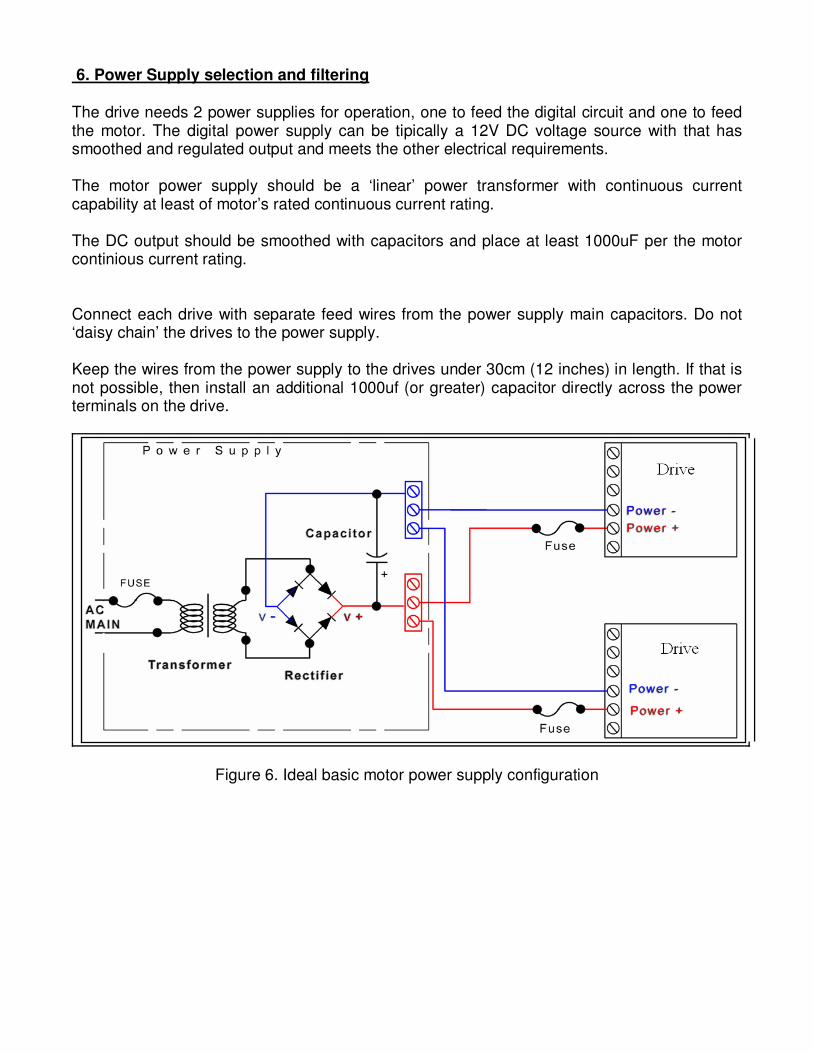
6. Power Supply selection and filtering The drive needs 2 power supplies for operation, one to feed the digital circuit and one to feed the motor. The digital power supply can be tipically a 12V DC voltage source with that has smoothed and regulated output and meets the other electrical requirements. The motor power supply should be a ‘linear’ power transformer with continuous current capability at least of motor’s rated continuous current rating. The DC output should be smoothed with capacitors and place at least 1000uF per the motor continious current rating. Connect each drive with separate feed wires from the power supply main capacitors. Do not ‘daisy chain’ the drives to the power supply. Keep the wires from the power supply to the drives under 30cm (12 inches) in length. If that is not possible, then install an additional 1000uf (or greater) capacitor directly across the power terminals on the drive.
Figure 6. Ideal basic motor power supply configuration

Using a switching mode power supply (SMPS) If using not a linear, but switching mode power supplies then do not connect the SMPS outputs directly to the drives, but connect a diode with it’s anode to the power supply positive output and place a capacitor to between the diode’s cathode and the negative (GND) output of the SMPS. When sizing the capacitor follow the rules described above in point 6. in this manual. The reason this extension circuit is needed is because most of the switching power supplies are not designed to power highly inductive loads (like motors). The problem is that the power supplies having too low capacitance on the outputs and the inductive kickback from the motors may rise the power supply Voltage and this could damage the drive and/or the power supply. The diode in the extension circuit blocks the reverse Voltage from the motor/drive to the power supply and the added external capacitor keeps the charge and the Voltage on the desired level and suppressing Voltage fluctation on the DC bus.
Figure 7. Extension circuit if using Switchind mode powersupply DSUB15, IDC-16 to DSUB-15 cable assembly The DSUB15 cable assembly contains an IDC-16 female connector crimped to a 15 wire ribbon cable’s one end and a DSUB15 female connector crimped to the other end of the ribbon cable. This cable assy can be used forexample to make a DSUB connection on a control box’s front panel with assembling the crimped DSUB connector directly to the control box’s wall facing out the box. The pinout of the cable assembly can be read in point 3.1.1 in this manual.

7. Troubleshooting
Q: The motor is oscillating over the nullpoint when powerup. A: Tune the PID controller with the Servoconfigurator3 software. Q: I like to control my motor with a PLC which has 24V I/Os, is it possible? A: Yes. The step and direction pins are feed through optoisolators. Use a series resistor with the step and with the direction signal from the PLC. Resistor must be sized so that the opto-isolator current is limited under 10mA. Q: I like to control a DC servomotor with the drive, is it possible? A: No. The drive can only control brushless type AC servomotors. To control a brush type servomotor check our DG3S servo drive series. Q: I have a motor that has a rated Voltage greater than 50VDC, can I used it with the drive. A: Yes, but do not connect a PSU with an overvoltage, absolute maximum motor Voltage ratings of the drive is 50VDC. If your motor has higher rated Voltage, it should be operate from 50VDC maximum and will have a limited maximum speed and torque. The best way is to use a higher Voltage rated drive in this case, if any available. For more information visit: http://www.cncdrive.com e-mail: info@cncdrive
Please consider the enviroment before printing this document.