user’s manual bcd-2000 - bixolonbixolon.com/upload/download/manual_bcd-2000_user... · 20 dtr...
TRANSCRIPT

User’s Manual
BCD-2000
Customer Display Rev. 1.00
http://www.bixolon.com

Rev. 1.00 - 2 -
BCD-2000
Introduction BCD-2000 is designed to be used while connected to computer peripherals and electronic devices such as ECR (Electronic Cash Register) and POS (Point Of Sales).
※ The main features of the printer are as follows:
1. Customer Display LCD Module Model 2. Character Number
- BCD-2000: 120 Letters(30 Letters x 4 Lines) - BCD-2000K: 40 Letters(20 Letters x 2 Lines)
3. Interface: RS232/USB Supported 4. Rotation Angle: Horizontal: +/-180˚,Vertical: 52˚ (5step) 5. Display Color: Background (Blue), Characters (White) 6. Emulation: ESC/POS, CD5220
It is advisable to read the contents of this manual carefully before using the printer for the first
time.
※ Use only authorized supplies that can be trusted!
- We are not responsible for quality and service for damage caused by the use of unauthorized products.
We at BIXOLON maintain ongoing efforts to enhance and upgrade the functions and quality of all our products. In following, product specifications and/or user manual content may be changed without prior notice.

Rev. 1.00 - 3 -
BCD-2000
Table of Contents 1. Product Models & Components .......................................................................................... 4 2. Unpacking ............................................................................................................................. 5
2-1 BCD-2000A/AU/DS Types ................................................................................................ 5 2-2 BCD-2000N/NU Types ...................................................................................................... 5 2-3 BCD-2000WA/WAU/WS Types ......................................................................................... 6 2-4 BCD-2000WN/WNU Types ............................................................................................... 6
3. Initial Settings & Options (Serial) ........................................................................................ 7
3-1 Direct Connection .............................................................................................................. 7 3-2 Pass Through .................................................................................................................... 8
4. Connection Types & Sizes................................................................................................... 9
4-1 Connection Types (BCD-2000A/N/DS/WA/WN/WDS) ...................................................... 9 4-2 How to Connect (BCD-2000AU/NU/WAU/WNU) ............................................................... 9 4-3 Sizes ............................................................................................................................... 11
5. Features .............................................................................................................................. 12
5-1 Swivel .............................................................................................................................. 12 5-2 Tilting............................................................................................................................... 13
6. Connection .......................................................................................................................... 14
6-1 Connecting Direct Connection Pin .................................................................................. 14 6-2 Serial Communication Connector (D-SUB 25PF) ............................................................ 16 6-3 USB Communication ....................................................................................................... 17
7. Switch (Power, Brightness, DIP Switch)........................................................................... 18
7-1 Power & Brightness Control Switches ............................................................................. 18 7-2 DIP Switch ....................................................................................................................... 19 7-3 VMSM (Virtual Memory Switch Manager) ....................................................................... 20
8. Power Control ..................................................................................................................... 21 9. Specifications ..................................................................................................................... 23

Rev. 1.00 - 4 -
BCD-2000
1. Product Models & Components • The following display models are available: 1) Desktop (BCD-2000A/AU/DS) 2) Desktop Mount (BCD-2000N/NU) 3) Wall Mount (BCD-2000WA/WAU/WN/WNU/WS)
BCD-2000A BCD-2000AU BCD-2000N BCD-2000NU BCD-2000DS
BCD-2000WA BCD-2000WAU BCD-2000WN BCD-2000WNU BCD-2000WS
* All models can be easily mounted on a wall or desk using an electric screwdriver.
BCD-2000N/NU/WN/WNU BCD-2000A/AU/DS/WA/WAU/WS
Caution or Warning - Please only use the screws supplied for the installation of the device.

Rev. 1.00 - 5 -
BCD-2000
2. Unpacking
2-1 BCD-2000A/AU/DS Types
Display Set Installation Guide CD Screws x 4 (M3x10) Tapping
2-2 BCD-2000N/NU Types
Display Set Installation Guide CD Screws x 4 (M3x10) Tapping

Rev. 1.00 - 6 -
BCD-2000
2-3 BCD-2000WA/WAU/WS Types
Display Set Installation Guide CD Screws x 4 (M3x10) Tapping
2-4 BCD-2000WN/WNU Types
Display Set Installation Guide CD Screws x 4 (M3x10) Tapping

Rev. 1.00 - 7 -
BCD-2000
3. Initial Settings & Options (Serial)
3-1 Direct Connection • Connected to the Display directly without passing through the board.
Item Display-Serial
Standard Model
BCD-2000N BCD-2000A
How to Connect a
Power Cable to the Serial
Cable
Connect an SMPS to the Serial Cable Jack
Voltage Used: 24V (2pin)
BCD-2000N+SMPS
Caution or Warning - The above image may be different from the actual items.

Rev. 1.00 - 8 -
BCD-2000
3-2 Pass Through
• Data transmits through Host(PC) → Display → Printer.
Item Display-Serial
Standard Model
BCD-2000DS
Standard Board
Specifications
Power (Optional)
24V, 2.5A 24V, 1.5A
Cable Types (Optional)
Serial Cable 9PM to 25PF
Power Cable 3P to 3P
Power Cable 3P to 2P
Caution or Warning - Please only use the genuine optional accessories.

Rev. 1.00 - 9 -
BCD-2000
4. Connection Types & Sizes
4-1 Connection Types (BCD-2000A/N/DS/WA/WN/WDS)
Standard Components
(Host PC Side)
▼
(Printer Side)
▼
(Display Side)
▼
Interface
A B C D E F
Power Connection 1
(Separate power supply needed
for Rinter/Display)
-
24VDC
OR
Power Connection 2
(SMPS→Display →Printer)
-
24VDC
Power Connection 3
(SMPS→Display →Printer)
-
24VDC
Serial Cable Connection 1
(Host→Display →Printer)
Serial Cable Connection 2
(Host→Printer) (Host→Display)
Misc.
A: Power Supply Connector (Output 24VDC, 3pin) B: Host Interface Connector (D-SUB 25pin, Female) C: Power Supply Connector (Input 24VDC, 2pin) D: Display Connector E: Printer Interface Connector (D-SUB 9pin, Male) F: Power Supply Connector (Input 24VDC, 3pin)
3 pin 3 pin
2 pin 3 pin
9 pin
25 pin
25 pin
9 pin
9 pin
9 pin
25 pin
25 pin
Rev. 1.00 - 10 -
BCD-2000
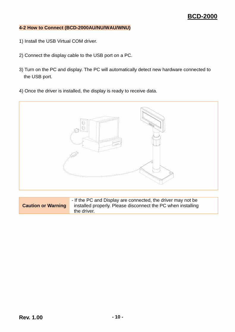
4-2 How to Connect (BCD-2000AU/NU/WAU/WNU)
1) Install the USB Virtual COM driver.
2) Connect the display cable to the USB port on a PC.
3) Turn on the PC and display. The PC will automatically detect new hardware connected to
the USB port.
4) Once the driver is installed, the display is ready to receive data.
Caution or Warning - If the PC and Display are connected, the driver may not be installed properly. Please disconnect the PC when installing the driver.

Rev. 1.00 - 11 -
BCD-2000
4-3 Sizes
4-3-1 Desktop Type
4-3-2 Wall Mount Type
4-3-3 Others
375mm
519mm 498mm
353mm
153mm 174mm
173mm 152mm
161mm
163mm 98mm
49mm
220mm 105mm
BCD-2000A/AU
76
mm
26
mm
32
mm
Ø76mm
BCD-2000DS
Rev. 1.00 - 12 -
BCD-2000
5. Features
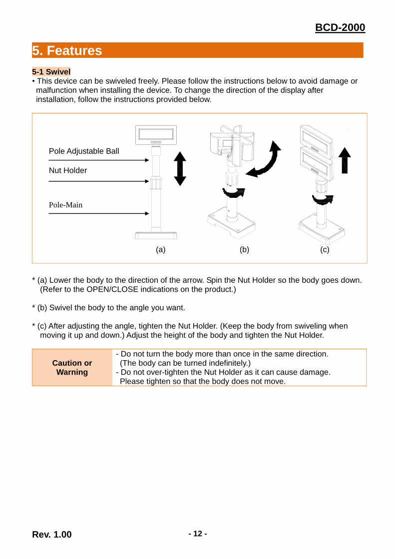
5-1 Swivel • This device can be swiveled freely. Please follow the instructions below to avoid damage or malfunction when installing the device. To change the direction of the display after installation, follow the instructions provided below.
(a) (b) (c)
* (a) Lower the body to the direction of the arrow. Spin the Nut Holder so the body goes down. (Refer to the OPEN/CLOSE indications on the product.)
* (b) Swivel the body to the angle you want. * (c) After adjusting the angle, tighten the Nut Holder. (Keep the body from swiveling when
moving it up and down.) Adjust the height of the body and tighten the Nut Holder.
Caution or Warning
- Do not turn the body more than once in the same direction. (The body can be turned indefinitely.) - Do not over-tighten the Nut Holder as it can cause damage. Please tighten so that the body does not move.
Pole Adjustable Ball
Nut Holder
Pole-Main
Rev. 1.00 - 13 -
BCD-2000
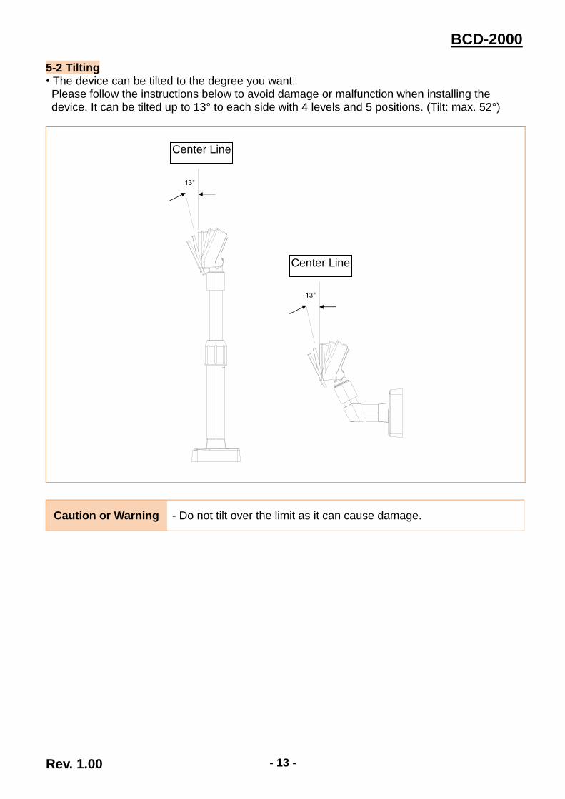
5-2 Tilting • The device can be tilted to the degree you want. Please follow the instructions below to avoid damage or malfunction when installing the device. It can be tilted up to 13° to each side with 4 levels and 5 positions. (Tilt: max. 52°)
Caution or Warning - Do not tilt over the limit as it can cause damage.
Center Line
Center Line
Rev. 1.00 - 14 -
BCD-2000
6. Connection
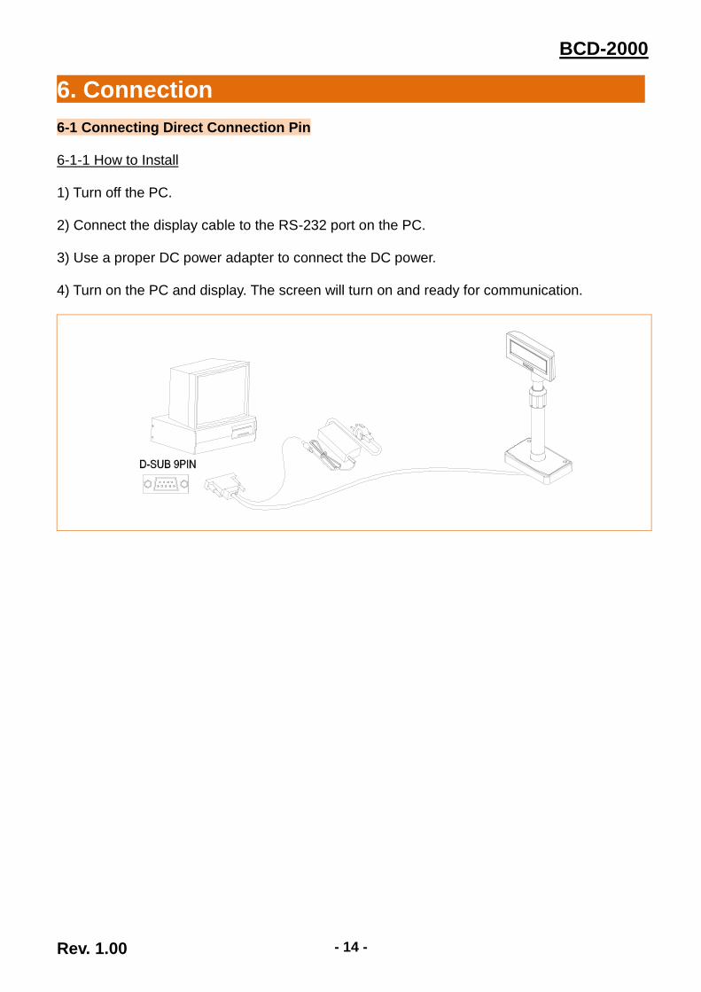
6-1 Connecting Direct Connection Pin 6-1-1 How to Install 1) Turn off the PC. 2) Connect the display cable to the RS-232 port on the PC. 3) Use a proper DC power adapter to connect the DC power. 4) Turn on the PC and display. The screen will turn on and ready for communication.

Rev. 1.00 - 15 -
BCD-2000
6-1-2 Serial Cable Pin Layout (D-SUB 9PF)
1 2 3 4 5 6 7 8 9
pin Name NC RXD TXD DTR GND DSR NC CTS NC
Short Connection
6-1-3 DC Power Jack
MAX +24VDC.
Caution or Warning
- Use only the genuine connection cable and adapter provided by the manufacturer. - The warranty does not cover damage caused by the use of unauthorized cables.
Rev. 1.00 - 16 -
BCD-2000
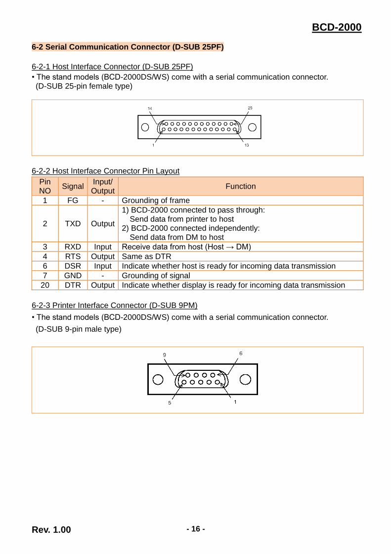
6-2 Serial Communication Connector (D-SUB 25PF)
6-2-1 Host Interface Connector (D-SUB 25PF)
• The stand models (BCD-2000DS/WS) come with a serial communication connector. (D-SUB 25-pin female type)
6-2-2 Host Interface Connector Pin Layout
Pin NO
Signal Input/ Output
Function
1 FG - Grounding of frame
2 TXD Output
1) BCD-2000 connected to pass through: Send data from printer to host
2) BCD-2000 connected independently: Send data from DM to host
3 RXD Input Receive data from host (Host → DM)
4 RTS Output Same as DTR
6 DSR Input Indicate whether host is ready for incoming data transmission
7 GND - Grounding of signal
20 DTR Output Indicate whether display is ready for incoming data transmission
6-2-3 Printer Interface Connector (D-SUB 9PM)
• The stand models (BCD-2000DS/WS) come with a serial communication connector.
(D-SUB 9-pin male type)

Rev. 1.00 - 17 -
BCD-2000
6-2-4 Printer Interface Connector Pin Layout
Pin NO
Signal Input/ Output
Function
2 RXD Input Receive data from printer (printer -> host)
3 TXD Output Send data to printer (DM -> printer)
4 DTR Output Indicate whether host is ready for incoming data transmission
5 GND - Grounding of signal
6 DSR Input Indicate whether display is ready for incoming data transmission
9 RESET Output Reset signal to printer (host -> printer)
Caution or Warning
- Use only the genuine communication cable provided by the manufacturer.
- The warranty does not cover damage caused by the use of unauthorized cables.
6-3 USB Communication
6-3-1 USB Interface Connector
6-3-2 USB Interface Connector Pin Layout
Pin No Signal Designation (Color) Function
Shell Shield Drain cable Grounding of frame
1 VBUS Red Host power
2 D- White Data line (D-)
3 D+ Green Data line (D+)
4 GND Black Grounding of signal
Caution or Warning - Please only use the genuine USB cable supplied by the
manufacturer to avoid damage or malfunction.

Rev. 1.00 - 18 -
BCD-2000
7. Switch (Power, Brightness, DIP Switch)
7-1 Power & Brightness Control Switches
7-1-1 Location
• The Power and Brightness Control switches are located at the bottom of the display.
7-1-2 Function
• Power Switch: turns on/off the power
• Brightness Control Switch: adjust the brightness level of the screen
Brightness Control Switch
(knob)
Power Switch
Bright
Dark

Rev. 1.00 - 19 -
BCD-2000
7-2 DIP Switch 7-2-1 Location & Features • The 2 DIP switches are located on the backside of the panel. The DIP switch cover can be removed by pressing the hook.
7-2-2 Settings
• RS-232 serial input and command emulation mode settings
No. Function Switch OFF Switch ON
1 Data Length 8 bits 7 bits
2 Parity Check Disable Enable
3 Parity Selection Odd Even
4~6 Data Rate
4 5 6 Data Rate 4 5 6 Data Rate
0 0 0 9,600 bps 1 0 0 115,200 bps
0 0 1 4,800 bps 1 0 1 57,600 bps
0 1 0 2,400 bps 1 1 0 38,400 bps
0 1 1 1,200 bps 1 1 1 19,200 bps
(“0”: S/W OFF, “1”: S/W ON)
7~8 Command Emulation
7 8 Command Emulation 7 8 Command Emulation
0 0 ESC/POS 0 1 Reserved
1 0 CD5220 1 1 Reserved
(“0”: S/W OFF, “1”: S/W ON)
Caution or Warning - Close the DIP switch cover before operation. - Turn off the DIP switch before changing the settings. - New DIP switch settings apply when powered on.

Rev. 1.00 - 20 -
BCD-2000
7-3 VMSM (Virtual Memory Switch Manager) • Other than DIP switch settings, you can change the following settings using VMSM software. The following settings apply when powered on and are executed by the initialization command.
1) MSW 1
Memory S/W
Function Default Content to be set Range to be set
1 Character code table
Selection n=0
Page 0 is selected
[BCD-2000] 0,17,18,20,27,31
[BCD-2000K] 0,1,2,3,4,5,14,15,16, 17,18,19,20,21,25,
26,27,28,29,30,31,32, 33,36,38,40,41,49,50,51
2 International character
set selection n=0 U.S.A is selected 0-15
3 Selection of the
peripheral devices n=2
Display is selected
1-3
4 Cursor display n=1 Cursor On 0, 1
5 ~ 8 Reserved - - -
2) MSW 2
Memory S/W
Function Default Content to be set Range to be set
1 Handshaking(BCD-2000) n=0 DTR/DSR 0: DTR/DSR 1: Xon/Xoff
2 BCD Mode Selection n=0 BCD-2000
0: BCD-2000 (8x16)
1: BCD-2000K (9x17)
3 ~ 8 Reserved n=0 - -
3) MSW 3
Memory S/W
Function Default Content to be set Range to be set
1 ~ 8 Reserved n=0 - -
Caution or Warning - If new settings do not apply, please contact your dealer for assistance.

Rev. 1.00 - 21 -
BCD-2000
8. Power Control
• The base board is located inside the base unit. Remove the PCB cover by pressing the hook on the base unit as shown in the image below.
Caution or Warning - Close the PCB cover before operation.
* Base Board
CN1 J2 J1
CN2
Jumper 1 (JP1) - Power
Jumper 2 (JP2)-Communication Cable

Rev. 1.00 - 22 -
BCD-2000
1) Jumper 1
Connection Mode JP1 Jack Type
Input Power (24VDC) 1-2 Position J1
Input Power (24VDC) 2-3 Position CN1
N/C 4-5 -
Out power to print (24VDC) (Pass Through)
5-6 Position CN2
2) Jumper 2
• Can be used when Data Pass Through mode or Printer Disabled mode is selected.
Connection Mode JP2 Function
Data Pass Through (Default)
1-2, 4-5 Can be connected to a printer that does not support ConneESC = command
Printer Disabled 2-3, 5-6 Do not use a printer
Caution or Warning - Do not set the jumper switch other than how specified above to avoid damage or malfunction.

Rev. 1.00 - 23 -
BCD-2000
9. Specifications
Display
Display Method STN LCD
Display Color Background / Text(Image)
Blue / White
Active Area (W) x (H) mm 118.5 x 45.5
Visual Area (W) x (H) mm 127.2 x 33.9
Brightness (cd/m²) 100
Character Number
(Letters) x (Lines) [BCD-2000]: 30 x 4 [BCD-2000K]: 20 x 2
Character Type(Set) [BCD-2000]: 95 Alphanumeric, 6 International [BCD-2000K]: 95 Alphanumeric, 30 International
Character Pattern (W) x (H) dot [BCD-2000]: 8*16 dot matrix [BCD-2000K]:9*17 dot matrix
Character Size (W) x (H) mm [BCD-2000]: 4.24 x 8.48 [BCD-2000K]: 4.77 x 9.01
Character Space (mm) 0.03
Receive Buffer [byte] 1K
Emulation ESC/POS, CD5220
Power & Interface
Power Voltage USB: 5VDC±5%(USB Bus Power) / RS232: 24VDC
Interface RS232 / USB
Software
Windows Driver Windows XP (32bit/64bit) / WEPOS/2003 Server (32bit/64bit) / 2008 Server (32bit/64bit) / VISTA (32bit/64bit) / Windows 7 (32bit/64bit) / Windows 8 (32bit/64bit) / Windows 10 (32bit/64bit)
OPOS Driver Windows XP (32bit/64bit) / WEPOS / 2003 Server (32bit/64bit) / 2008 Server (32bit/64bit) / VISTA (32bit/64bit) / Windows 7 (32bit/64bit) / Windows 8 (32bit/64bit) / Windows 10 (32bit/64bit)
SDK Windows, Android, iOS SDK
Exterior
Body Color Ivory / Dark-Gray
Rotation Angle horizontal: +/-180˚; vertical: 52˚ (5 positions)
Overall Dimension
(W) x (D) x (H) mm
BCD-2000A/AU: 162.5 x 97.6 x 167~521 BCD-2000N/NU: 161 x 75.8 x 153~507 BCD-2000DS: 220.4 x 105.4 x 174~528 BCD-2000WA/WAU: 162.5 x 166 x 189 BCD-2000WN/WNU: 161 x 152 x 178 BCD-2000WS: 220.4 x 173 x 193
Product weight (g) 844G (BCD-2000AU)
Environment & Reliability
Operating Temperature
[℃] / [℉] 0 ~ 40 / 32 ~ 104
Operating Humidity [%] 10 ~ 80
Storage Temperature
[℃] / [℉] -20 ~ 55 / -4 ~ 140
Storage Humidity [%] 10 ~ 90
Reliability (Display) (hours) 50,000 (Backlight)

Rev. 1.00 - 24 -
BCD-2000
Warning - U.S.A This equipment has been tested and found to comply with the limits for a Class A digital device pursuant to Part 15 of the FCC Rules. These limits are designed to provide reasonable protection against harmful interference when the equipment is operated in a commercial environment. This equipment generates uses, and can radiate radio frequency energy and, if not installed and used in accordance with the instruction manual, may cause harmful interference to radio communications. Operation of this equipment in a residential area is likely to cause harmful interference in which case the user will be required to correct the interference at his own expense. ii) Changes or modifications not expressly approved by the manufacturer could void the user's authority to operate the equipment.
Notice - Canada i) Class A Digital Device : Wired Device This Apparatus complies with class “A” limits for radio interference as specified in the Canadian department of communications radio interference regulations. Get appareil est conforme aux normes class “A” d’interference radio tel que specifier par ministre canadien des communications dans les reglements d’interference radio.
Caution
Some semiconductor devices are easily damaged by static electricity. You should turn the display “OFF”, before you connect or remove the cables on the rear side, in order to guard the display against the static electricity. If the display is damaged by the static electricity, you should turn the display “OFF”.
Waste Electrical and Electric Equipment (WEEE) This marking shown on the product or its literature, indicates that is should not be disposed with other household wastes at the end of its working life, To prevent possible harm to the environment or human health from uncontrolled waste disposal, please separate this from other types of wastes and recycle it responsibly to promote the sustainable reuse of material resources. Household
users should contact either the retailer where they purchased this product, or their local government office, for details of where and how they can take this item for environmentally safe recycling. Business users should contact their supplier and check the terms and conditions of the purchase contract. This product should not be mixed with other commercial wastes for disposal.

Rev. 1.00 - 25 -
BCD-2000
Revision history
Rev. Date Page Description
1.00 10.05.17 - New