user's manual - farmtek use this product after reading this user's manual for your safety....
TRANSCRIPT

Rev1
User's Manual
MODEL DPW-099 DPW-120
1. Safety Warnings 2 2. Names of Components 8 3. Proper Operation
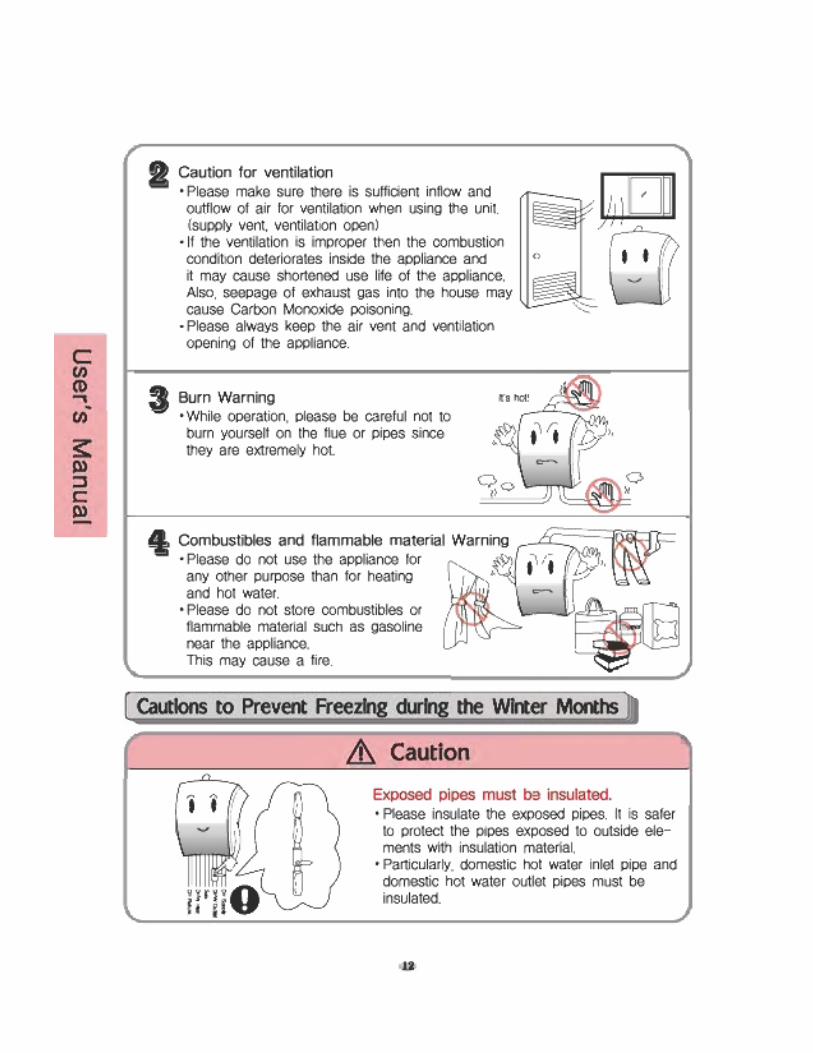
- Before Operation 10- Cautions when in use 11- Cautions to Prevent Freezing during
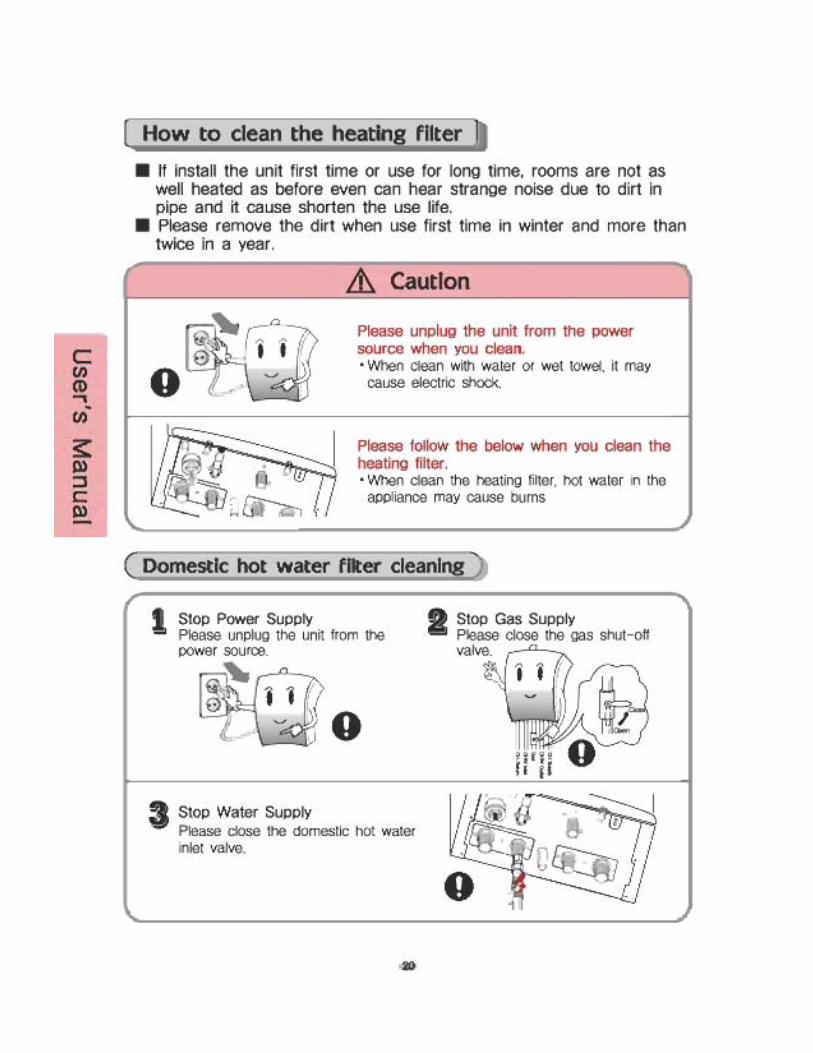
the Winter Months 12- How to use the thermostat 15- How to clean the filter 20- How to refill water 24
4. Checkpoints before using phonereservation . 26
5. Specification 276. Troubleshooting 32
WARNINGThis product must be installed and serviced by a licensed plumber, a licensedgas fitter, or a professional service technician and/or in accordance with alllocal code. Improper installation and/or operation, or installation by an unqualifiedperson, will void the warranty.
WARNINGOperation of this unit creates carbon monoxide gas and flue gases which can cause serious injury or death. In addition, if the information in this manual isnot followed exactly, a fire or explosion may result causing property damage,personal injury or death.
* This User's Manual can bemodified without prior noti-fication for product qualityimprovement purpose.
Please use this product after reading this User's Manual for your safety.


DPW-099A DPW-120AHeating System DataHeat Input (Btu/h) 47,800 - 99,000 47,800 - 120,000AFUE (%) 90 90Htg Water Temp (DegF)Working Pressure (psi)Freeze Protection DeviceHeating Min Flow (GPM)Htg Heat Exch Water Volume (gal) 0.2 0.2Ignition Type
Domestic Hot Water DHW Production Energy Factor 0.83 0.85Temperature SettingDHW Minimum Flow Rate (GPM)GPM at 50F in 100F Out 3.7 4.5GPM at 50F in 110F Out 3.1 3.7GPM at 50F in 120F Out 2.6 3.2GPM at 50F in 130F Out 2.3 2.8
General DataControl VoltageFuel TypeNatural Gas Inlet Press ("WC) LP Gas Inlet Pressure ("WC)Gas line Size (inch)Unit Voltage (V)Power Consumption (W) 120 140Pump Flow @ 10ft HeadNOX Levels (ppm) 20 20
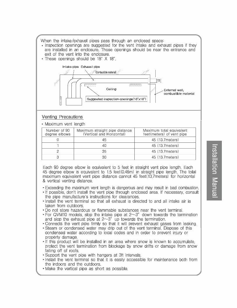
VentingMax Flue Temp (DegF)Venting MaterialMax Vent Length (feet)Max number of Elbows**One Elbow = 5 ft equivalent length, which must be deducted from the total vent length
DimensionsWeight (lbs) 70 70Unit Height (less vent conns) (") 27 5/8" 27 5/8"Width (") 18 1/8" 18 1/8"Depth (") 8" 8"Gas Connection Size (")Heating Supply/Return (")DHW Inlet/Outlet (")Flue/Air Intake (")Quietside maintains a policy of continuous product development and specifications can change
115V-1Ph-60Hz
45ft Equivalent each for both Intake and Exhaust3 per Individual Vent pipe
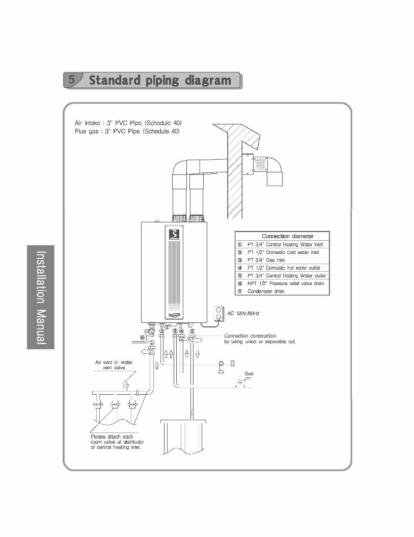
Vent Connection ø3.5" to accept 3" PVC
2.5 GPM
Electronic Spark
Controlled : Settings of 98 - 114°F, 120°F, 130°F, 140°F
NG or Field Conversion to LP
Min Size 3/4"
Product Specifications
Minimum 9" WC to Maximum 13" WCMinimum 5.8" WC to Maximum 9.7" WC
Ø3" Schedule 40 PVC
24V DC - Requires X-X or Zero Voltage Contact for Zone applications
1.2
15 - 20Thermistor, will energize pump/combustion
0.7 GPM
122 to 176 DegF leaving unit Heat Exchanger
Quietside West : 8750 Pioneer Blvd, Santa Fe Springs CA 90670 : Tel 562 699 6066, Fax 562 699 4351Quietside East : 6 Pine Hill Drive, Carlisle PA 17013 : Tel 717 243 2535, Fax 717 243 7917
www. Quietside.com
136
3/4"3/4"1/2"


DPW Dip Switch Settings
Depending on the application of the DPW unit it may be necessary to alter theDip Switch settings from the standard positions
The unit has 5 Dip Switches located on the Microprocessor
Dip Switch Standard Setting Controls1 ON Fuel Gas Type2 OFF Fuel Gas Type3 OFF Unit Options4 OFF Forced Minimum Firing rate5 OFF Forced Maximum Firing rate
Setting for Natural Gas OperationDip Switch Setting for NG
1 ON2 OFF
Setting for LP Gas OperationDip Switch Setting for LP
1 OFF2 ON
Unit Options
Switch Dip Switch #3 to ON
On DSR-100F press the Timers and Anti-Freeze buttons simultaneously for 5 seconds. This will allow unit to enter the programming mode
Temperature display can be changed between DegF and DegC by pressing theTimer button 3 times until Lc is displayed in the top RH corner of the unit display,and f is displayed in the center of the screen
Press the Up temperature arrow and the f will change to a c
Hit the Power On/Off button to exit and switch Dip Switch #3 to OFF, the unit willnow display in DegC
Cont
Zone ControlThis can be also be set up using this control (see zone control wiring section formore detail)
Minimum Firing Rate
Setting Dip Switch #4 to ON will lock the unit into the minimum firing rate at alltimes. This is occasionally used for troubleshooting and gas pressure set uppurposes. Move the switch back to OFF to allow the unit to modulate capacity.
Maximum Firing Rate
Setting Dip Switch #5 to ON will lock the unit into the maximum firing rate at alltimes. This is occasionally used for troubleshooting and gas pressure set uppurposes. Move the switch back to OFF to allow the unit to modulate capacity
2

Specific requirements for installation in Massachusetts
In the Commonwealth of Massachusetts these units must be installed by a licensed gas fitter or plumber
Venting : For the Quietside models DPW-099A, DPW-120A where the bottom of the venttermination and combustion air intake is installed at a height BELOW 4 ft abovethe grade level the following requirements must be satisfied
1. If there is not one presently installed, on each floor level where there is a bedroom(s), a Carbon Monoxide detector and alarm shall be installed inthe living area outside the bedroom(s). The Carbon Monoxide detectorshall comply with NFPA 720 (2005 Edition)
2. A Carbon Monoxide detector shall be installed in the room where theODW unit is installed, the detector shall be :
a) Powered from the same power circuit that provides power for the ODWunit. A single electrical service switch shall be used to service both theunit and the detector
b) Have battery back up powerc) Meet ANSI/UL std 2034 and comply with NFPA 720 (2005 Edition)d) Approved and listed by a NRTL recognized under 527 CMR
3. A Quietside approved vent termination must be used. Installation of thevent terminal must be in strict compliance with Quietside's writteninstructions, and a copy of these instructions must remain with the unitafter the installation is completed.
4. A metal or plastic identification plate shall be mounted on the exterior ofthe building, 4ft above the vent termination. The plate shall read "GasVent Directly Below" with text size visible from a minimum of 8ft.
3

Cont
For the Quietside models listed above where the bottom of the vent terminationand combustion air intake is installed at a height of 4ft ABOVE the grade levelthe following requirements must be satisfied
1. If there is not one presently installed, on each floor level where there is a bedroom(s), a Carbon Monoxide detector and alarm shall be installed inthe living area outside the bedroom(s). The Carbon Monoxide detectorshall comply with NFPA 720 (2005 Edition)
2. A Carbon Monoxide detector shall be installed in the room where theODW unit is installed, the detector shall be :
a) Powered from the same power circuit that provides power for the ODWunit. A single electrical service switch shall be used to service both theunit and the detector
b) Have battery back up powerc) Meet ANSI/UL std 2034 and comply with NFPA 720 (2005 Edition)d) Approved and listed by a NRTL recognized under 527 CMR
3. A Quietside approved vent termination must be used. Installation of thevent termination must be in strict compliance with Quietside's writteninstructions, and a copy of these instructions must remain with the unitafter the installation is completed.
Vent Termination requirementsAs the DPW unit is a condensing product
The Vent for all Quietside DPW units shall not terminate
Over Public Walkways; or
Near soffit vents or crawl space vents or other area where condensate or vaporcould create a nuisance or hazard or cause property damage; or
Where condensate or vapor could cause damage or could be detrimental to theoperation of regulators, relief valves, or other equipment
4

Specific requirements for installation in Canada
The provinces of Ontario and Alberta have adopted standard ULC S636 requiringthe following additional items to be noted.
1. Maximum flue temperature as tested is 136 DegF, allowing theseunits to be vented with Schedule 40 PVC under the regulation ofULC S636.
2. Under the new requirements of ULC S636 regarding ventconnections to the unit, Quietside requires the Schedule 40 Ventpiping to be secured to the unit using approved PVC cement,following the cement manufacturers instructions regardingmethodology and curing time. A bead of high temperature siliconeshould be also run around the joint to ensure no leaks can occur.
5
Combustion and Leak Testing of DPW units
As the front cover of the unit is mechanically attached and cannot be removed inoperation without the use of a tool, it is not permissible to conduct combustiontesting or leak testing of the unit with the front cover removed.
Combustion testing must be achieved by using a calibrated combustion tester,with the probe inserted either in the flue exhaust of the vent termination or it ispermissible to take reading by accessing the flue pipe approximately 12" abovethe unit, providing adequate provisions are made for sealing any access aftertesting to ensure no leakage of flue gases into the occupied space.
Leak testing must take place with the end of the "sniffer probe" at least 1" fromany surface of the unit to ensure that false readings cannot be obtained.
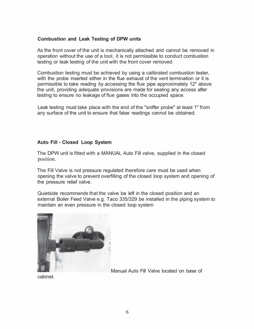
Auto Fill - Closed Loop System
The DPW unit is fitted with a MANUAL Auto Fill valve, supplied in the closedposition.
The Fill Valve is not pressure regulated therefore care must be used whenopening the valve to prevent overfilling of the closed loop system and opening ofthe pressure relief valve.
Quietside recommends that the valve be left in the closed position and anexternal Boiler Feed Valve e.g. Taco 335/329 be installed in the piping system tomaintain an even pressure in the closed loop system
Manual Auto Fill Valve located on base of
6
cabinet.
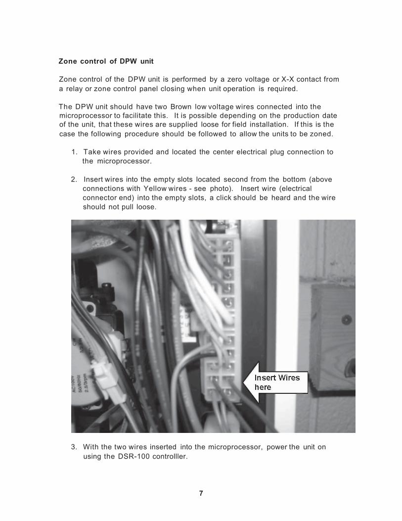
Zone control of DPW unit
Zone control of the DPW unit is performed by a zero voltage or X-X contact froma relay or zone control panel closing when unit operation is required.
The DPW unit should have two Brown low voltage wires connected into themicroprocessor to facilitate this. It is possible depending on the production dateof the unit, that these wires are supplied loose for field installation. If this is thecase the following procedure should be followed to allow the units to be zoned.
1. Take wires provided and located the center electrical plug connection tothe microprocessor.
2. Insert wires into the empty slots located second from the bottom (aboveconnections with Yellow wires - see photo). Insert wire (electricalconnector end) into the empty slots, a click should be heard and the wireshould not pull loose.
3. With the two wires inserted into the microprocessor, power the unit onusing the DSR-100 controlller.
7

Cont
4. Switch Dip Switch # 3 to the ON position.
5. Simultaneously press both the Timer and Anti Freeze buttons on thecontroller for 5 seconds
6. The control will now enter the option set up mode, press the Timer buttonuntil the display in the top RH corner of the unit reads C6.
7. Press the Up Temperature key, to change the display from 2n to 3n
8. Press the unit On/Off button to turn off the control
9. Switch Dip Switch # 3 back to the OFF position
10. When the zone control wires are closed the unit will now operate andprovide closed loop heating water at the temperature set on the DSR-100
Anti-Freeze & Freeze Protection
For Anti Freeze protection in the Quietside units the following products arerecommended "No Burst"
"Fernox Alphii"
The maximum concentration allowed is 30% by volume which will protect the unitdown to approximately 5 DegF or -11 DegC
8

Pump Curves - DPW Units
The DPW units include a pump assembly that is used to provide the flow throughthe unit heat exchangers, and has a nominal flow of heating water for externalpiping arrangements.
This pump is not designed to be the system pump providing flow to radiant loopsor baseboard.
Therefore Quietside insists on using a Primary - Secondary pumpingarrangement, the recommended method uses the traditional large diameterPrimary loop
The main circulation pump or the zone pumps will then provide circulation intothe zones or the heating system
The only exception to this Primary - Secondary rule is for Air Handling units witha hot water coil where the Air Handling unit is located less than 10ft from theDPW unit.
9

Unit Controls & Zoning
A DSR-100F Controller is provided with the unit.
This is not used as a thermostat, but is a unit controller and should be mountedadjacent to the DPW unit. It is connected to the DPW via the 2 Yellow wires andis powered by 20V DC.
The DSR controller allows both the heating loop and DHW water temperatures tobe set
When the unit is started using the X - X or dry contacts on the microprocessor itwill operate and provide heating loop water at the set temperature until thezone(s) are satisfied. If a DHW call is experienced during heating operation theunit will automatically switch over to provide DHW.
DO NOT APPLY 24V AC OR LINE VOLTAGE TO THE X - X CONTACTSUNIT MICROPROCESSOR WILL FAIL IF IT RECEIVES 24V AC OR LINEVOLTAGE ON THESE CONTACTS
It is not permissible to power the secondary loop pump from the Primary looppump installed in the unit.Power for the Secondary loop pump should come from a switching relay e.gTaco SR501.
10
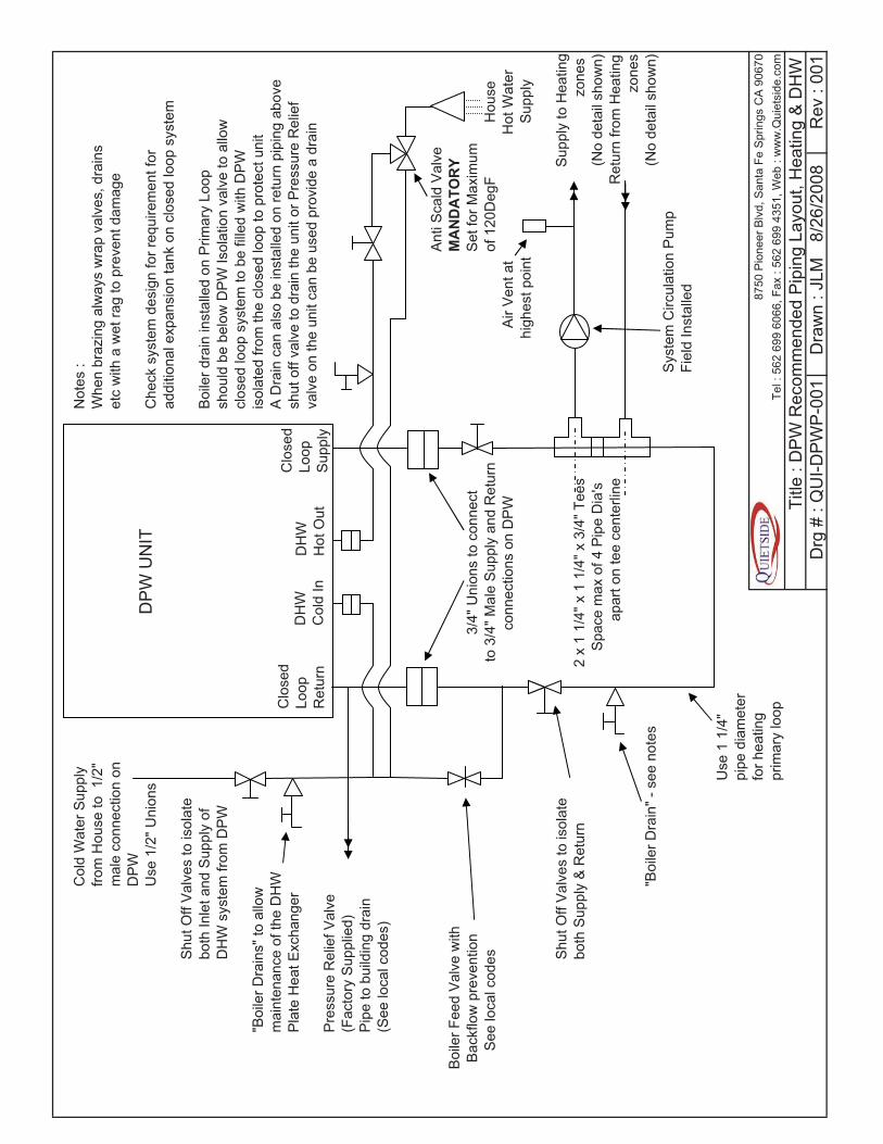
Col
d W
ater
Sup
ply
Not
es :
from
Hou
se to
1/2
"W
hen
braz
ing
alw
ays
wra
p va
lves
, dra
ins
mal
e co
nnec
tion
onet
c w
ith a
wet
rag
to p
reve
nt d
amag
eD
PW
Use
1/2
" Uni
ons
Che
ck s
yste
m d
esig
n fo
r req
uire
men
t for
ad
ditio
nal e
xpan
sion
tank
on
clos
ed lo
op s
yste
mS
hut O
ff V
alve
s to
isol
ate
both
Inle
t and
Sup
ply
ofB
oile
r dra
in in
stal
led
on P
rimar
y Lo
opD
HW
sys
tem
from
DP
Wsh
ould
be
belo
w D
PW
Isol
atio
n va
lve
to a
llow
cl
osed
loop
sys
tem
to b
e fil
led
with
DP
W"B
oile
r Dra
ins"
to a
llow
isol
ated
from
the
clos
ed lo
op to
pro
tect
uni
t m
aint
enan
ce o
f the
DH
WA
Dra
in c
an a
lso
be in
stal
led
on re
turn
pip
ing
abov
e P
late
Hea
t Exc
hang
ersh
ut o
ff va
lve
to d
rain
the
unit
or P
ress
ure
Rel
ief
valv
e on
the
unit
can
be u
sed
prov
ide
a dr
ain
Pre
ssur
e R
elie
f Val
ve(F
acto
ry S
uppl
ied)
Pip
e to
bui
ldin
g dr
ain
(See
loca
l cod
es)
Ant
i Sca
ld V
alve
Boi
ler F
eed
Val
ve w
ithM
AN
DA
TOR
YB
ackf
low
pre
vent
ion
3/4"
Uni
ons
to c
onne
ctS
et fo
r Max
imum
See
loca
l cod
es
to 3
/4" M
ale
Sup
ply
and
Ret
urn
of 1
20D
egF
Hou
seco
nnec
tions
on
DP
WA
ir V
ent a
t H
ot W
ater
high
est p
oint
Sup
ply
Shu
t Off
Val
ves
to is
olat
e S
uppl
y to
Hea
ting
both
Sup
ply
& R
etur
n2
x 1
1/4"
x 1
1/4
" x 3
/4" T
ees
zone
sS
pace
max
of 4
Pip
e D
ia's
(N
o de
tail
show
n)ap
art o
n te
e ce
nter
line
Ret
urn
from
Hea
ting
zone
s"B
oile
r Dra
in" -
see
not
es
(No
deta
il sh
own)
Sys
tem
Circ
ulat
ion
Pum
pFi
eld
Inst
alle
d
Use
1 1
/4"
pipe
dia
met
er
for h
eatin
g87
50 P
ione
er B
lvd,
San
ta F
e S
prin
gs C
A 9
0670
prim
ary
loop
Tel :
562
699
606
6, F
ax :
562
699
4351
, Web
: w
ww
.Qui
etsi
de.c
om
Title
: D
PW
Rec
omm
ende
d P
ipin
g La
yout
, Hea
ting
& D
HW
Drg
# :
QU
I-DP
WP
-001
Dra
wn
: JLM
8/26
/200
8R
ev :
001
DP
W U
NIT
Clo
sed
Loop
Sup
ply
Clo
sed
Loop
Ret
urn
DH
WH
ot O
utD
HW
Col
d In

Col
d W
ater
Sup
ply
Not
es :
from
Hou
se to
1/2
"W
hen
braz
ing
alw
ays
wra
p va
lves
, dra
ins
mal
e co
nnec
tion
onet
c w
ith a
wet
rag
to p
reve
nt d
amag
eD
PW
Use
1/2
" Uni
ons
Boi
ler d
rain
inst
alle
d on
pip
ing
shou
ld b
e be
low
DP
W Is
olat
ion
valv
e to
allo
w
Shu
t Off
Val
ves
to is
olat
e cl
osed
loop
sys
tem
to b
e fil
led
with
DP
Wbo
th In
let a
nd S
uppl
y of
isol
ated
from
the
clos
ed lo
op to
pro
tect
uni
t D
HW
sys
tem
from
DP
WA
Dra
in c
an a
lso
be in
stal
led
on re
turn
pip
ing
abov
e "B
oile
r Dra
ins"
to a
llow
shut
off
valv
e to
dra
in th
e un
it or
Pre
ssur
e R
elie
fm
aint
enan
ce o
f the
DH
Wva
lve
on th
e un
it ca
n be
use
d pr
ovid
e a
drai
nP
late
Hea
t Exc
hang
er
Pre
ssur
e R
elie
f Val
ve(F
acto
ry S
uppl
ied)
Pip
e to
bui
ldin
g dr
ain
(See
loca
l cod
es)
Ant
i Sca
ld V
alve
Boi
ler F
eed
Val
ve w
ithM
AN
DA
TOR
YB
ackf
low
pre
vent
ion
3/4"
Uni
ons
to c
onne
ctS
et fo
r Max
imum
See
loca
l cod
es
to 3
/4" M
ale
Sup
ply
and
Ret
urn
of 1
20D
egF
Hou
seco
nnec
tions
on
DP
WA
ir V
ent a
t H
ot W
ater
high
est p
oint
Sup
ply
Coi
l Inl
etS
hut O
ff V
alve
s to
isol
ate
both
Sup
ply
& R
etur
nS
yste
m is
des
igne
d fo
r the
A
ir H
andl
er to
be
loca
ted
nom
ore
than
10f
t fro
m th
e D
PW
an
d no
mor
e th
an 5
ft ab
ove
"Boi
ler D
rain
" - s
ee n
otes
or
bel
ow th
e D
PW
Air
Han
dler
sho
uld
not h
ave
it's
own
circ
ulat
or in
stal
led
Dis
conn
ect p
ump
if in
stal
led
Use
max
ø1"
pip
e fo
r Sup
ply
& R
etur
n to
AH
U.
Max
tota
l pip
e87
50 P
ione
er B
lvd,
San
ta F
e S
prin
gs C
A 9
0670
leng
th (S
uppl
y &
Ret
urn)
20f
tTe
l : 5
62 6
99 6
066,
Fax
: 56
2 69
9 43
51, W
eb :
ww
w.Q
uiet
side
.com
Title
: D
PW
Rec
omm
ende
d P
ipin
g La
yout
, AH
U (N
o P
ump)
& D
HW
Drg
# :
QU
I-DP
WP
-002
Dra
wn
: JLM
8/26
/200
8R
ev :
001
DP
W U
NIT
Clo
sed
Loop
Sup
ply
Clo
sed
Loop
Ret
urn
DH
WH
ot O
utD
HW
Col
d In
AH
UU
nit
HW
Coi
l
Clo
sed
Loop
Hea
ting
Sys
tem
Not
es :
QS
DH
S D
HW
Sys
tem
Not
es :
Whe
n br
azin
g al
way
s w
rap
valv
es, d
rain
s Ta
nk s
yste
m a
lso
incl
udes
Tan
k D
rain
and
et
c w
ith a
wet
rag
to p
reve
nt d
amag
eP
/R V
alve
(sup
plie
d lo
ose)
Thes
e sh
ould
be
inst
alle
d an
d pi
ped
in
Che
ck s
yste
m d
esig
n fo
r req
uire
men
t for
ac
cord
ance
with
loca
l cod
esad
ditio
nal e
xpan
sion
tank
on
clos
ed lo
op s
yste
m
Boi
ler d
rain
inst
alle
d on
Sup
ply
to c
lose
d lo
opsh
ould
be
belo
w D
PW
Isol
atio
n va
lve
to a
llow
cl
osed
loop
sys
tem
to b
e fil
led
with
DP
W
Hou
seis
olat
ed fr
om th
e cl
osed
loop
to p
rote
ct u
nit
Hot
Wat
erA
Dra
in c
an a
lso
be in
stal
led
on re
turn
pip
ing
abov
e S
uppl
ysh
ut o
ff va
lve
to d
rain
the
unit
or P
ress
ure
Rel
ief
valv
e on
the
unit
can
be u
sed
prov
ide
a dr
ain
DP
W D
HW
Inle
t &A
nti S
cald
Val
veP
ress
ure
Rel
ief V
alve
Out
let c
onne
ctio
nM
AN
DA
TOR
YP
ipe
to b
uild
ing
drai
n si
zes
are
1/2"
Sup
plie
d w
ith Q
SD
HS
(S
ee lo
cal c
odes
)M
ax S
ettin
g 12
0Deg
FFr
omø3
/4" N
PT
Con
nect
ion
3/4"
Uni
ons
to c
onne
ctD
PW
DH
Wto
3/4
" Mal
e S
uppl
y an
d R
etur
nTo
DP
WO
utle
tco
nnec
tions
on
DP
WD
HW
Inle
t
Air
Ven
t at
"Boi
ler D
rain
" - s
ee n
otes
hi
ghes
t poi
ntø3
/4"N
PT
Shu
t Off
Val
ves
tois
olat
e D
PW
from
Air
Han
dler
Use
ø1
1/4"
pip
efo
r Prim
ary
Loop
ø3/4
"NP
Tø1
" NP
TS
uppl
y to
Hea
ting
zone
s Ta
co 0
08 B
ronz
e P
ump
(No
deta
il sh
own)
c/w
IFC
and
Shu
t offs
Col
d W
ater
Inle
tR
etur
n fro
m H
eatin
gS
uppl
ied
with
QS
DH
Sfro
m H
ouse
sup
ply
zone
s(N
o de
tail
show
n)87
50 P
ione
er B
lvd,
San
ta F
e S
prin
gs C
A 9
0670
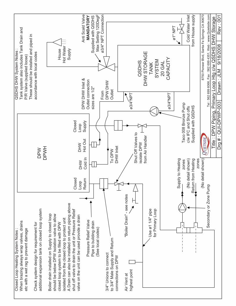
Sec
onda
ry o
r Zon
e P
ump
Tel :
562
699
606
6, F
ax :
562
699
4351
, Web
: w
ww
.Qui
etsi
de.c
om
Title
: D
PW
Pip
ing,
Prim
ary
Loop
Htg
c/w
QS
DH
S D
HW
Sto
rage
D
rg #
: Q
UI-D
PW
P-0
03D
raw
n : J
LM9/
18/2
008
Rev
: 00
1
DP
WD
PW
H
QS
DH
SD
HW
STO
RA
GE
TAN
KS
YS
TEM
20 G
AL
CA
PA
CIT
Y
Clo
sed
Loop
Sup
ply
DH
WH
ot O
utD
HW
Col
d In
Clo
sed
Loop
Ret
urn

Clo
sed
Loop
Hea
ting
Sys
tem
Not
es :
QS
DH
S D
HW
Sys
tem
Not
es :
Whe
n br
azin
g al
way
s w
rap
valv
es, d
rain
s Ta
nk s
yste
m a
lso
incl
udes
Tan
k D
rain
and
et
c w
ith a
wet
rag
to p
reve
nt d
amag
eP
/R V
alve
(sup
plie
d lo
ose)
Thes
e sh
ould
be
inst
alle
d an
d pi
ped
in
Sys
tem
is d
esig
ned
for t
he A
ir H
andl
er to
be
loca
ted
acco
rdan
ce w
ith lo
cal c
odes
no m
ore
than
10f
t fro
m th
e D
PW
and
no
mor
eth
an 5
ft ab
ove
or b
elow
the
DP
W
Boi
ler d
rain
inst
alle
d on
Sup
ply
to c
lose
d lo
opsh
ould
be
belo
w D
PW
Isol
atio
n va
lve
to a
llow
H
ouse
clos
ed lo
op s
yste
m to
be
fille
d w
ith D
PW
H
ot W
ater
isol
ated
from
the
clos
ed lo
op to
pro
tect
uni
t S
uppl
yA
Dra
in c
an a
lso
be in
stal
led
on re
turn
pip
ing
abov
e sh
ut o
ff va
lve
to d
rain
the
unit
or P
ress
ure
Rel
ief
valv
e on
the
unit
can
be u
sed
prov
ide
a dr
ain
DP
W D
HW
Inle
t &A
nti S
cald
Val
veO
utle
t con
nect
ion
MA
ND
ATO
RY
Pre
ssur
e R
elie
f Val
vesi
zes
are
1/2"
Sup
plie
d w
ith Q
SD
HS
P
ipe
to b
uild
ing
drai
n M
ax S
ettin
g 12
0Deg
F(S
ee lo
cal c
odes
)Fr
omø3
/4" N
PT
Con
nect
ion
3/4"
Uni
ons
to c
onne
ctD
PW
DH
Wto
3/4
" Mal
e S
uppl
y an
d R
etur
nTo
DP
WO
utle
tco
nnec
tions
on
DP
WD
HW
Inle
t
Air
Ven
t at
"Boi
ler D
rain
" - s
ee n
otes
hi
ghes
t poi
ntø3
/4"N
PT
Shu
t Off
Val
ves
tois
olat
e D
PW
from
Air
Han
dler
Use
max
ø1"
pip
e fo
r Sup
ply
& R
etur
n to
AH
U.
Max
tota
l pip
ele
ngth
(Sup
ply
& R
etur
n) 2
0ft
ø1" N
PT
Taco
008
Bro
nze
Pum
pø3
/4"N
PT
c/w
IFC
and
Shu
t offs
Sup
plie
d w
ith Q
SD
HS
Col
d W
ater
Inle
tfro
m H
ouse
sup
ply
8750
Pio
neer
Blv
d, S
anta
Fe
Spr
ings
CA
906
70
Tel :
562
699
606
6, F
ax :
562
699
4351
, Web
: w
ww
.Qui
etsi
de.c
om
Title
: D
PW
Pip
ing,
Clo
se c
oupl
ed A
HU
c/w
QS
DH
S D
HW
Sto
rage
D
rg #
: Q
UI-D
PW
P-0
04D
raw
n : J
LM9/
18/2
008
Rev
: 00
1
DP
WD
PW
H
AH
UU
nit
HW
Coi
l
QS
DH
SD
HW
STO
RA
GE
TAN
KS
YS
TEM
20 G
AL
CA
PA
CIT
Y
Clo
sed
Loop
Sup
ply
DH
WH
ot O
utD
HW
Col
d In
Clo
sed
Loop
Ret
urn

NO
TES
TO S
ET
DS
R-1
00F
DS
R-1
00F
1P
RE
SS
UN
IT O
N/O
FF B
UTT
ON
2P
RE
SS
HE
ATI
NG
SE
T TE
MP
ER
ATU
RE
BU
TTO
NY
EL
3U
SE
UP
AN
D D
OW
N A
RR
OW
S
TO S
ELE
CT
DE
SIR
ED
HE
ATI
NG
YE
LW
ATE
R T
EM
PE
RA
TUR
ER
AN
GE
122
-176
DE
GF
BR
NB
RN
4P
RE
SS
DH
W S
ET
TEM
PE
RA
TUR
E B
UTT
ON
5U
SE
UP
AN
D D
OW
N A
RR
OW
S
TO S
ELE
CT
DE
SIR
ED
DH
WW
ATE
R T
EM
PE
RA
TUR
E98
-114
DE
GF,
120
, 130
, 140
DE
GF
WH
EN
X-X
CO
NTA
CT
IS C
LOS
ED
UN
ITW
ILL
STA
RT
AN
D P
RO
VID
E C
LOS
ED
LO
OP
HE
ATI
NG
WA
TER
AT
THE
TEM
PE
RA
TUR
E S
ELE
CTE
D
DH
W P
RIO
RIT
Y W
ILL
BE
MA
INTA
INE
D
WH
EN
TH
E Z
ON
E(S
) SA
TIS
FY T
HE
UN
ITW
ILL
SH
UT
DO
WN
, DS
R W
ILL
RE
MA
IN L
IT
AT
ALL
TIM
ES
THIS
IS T
HE
PR
EFE
RR
ED
ME
THO
D T
O
CO
NTR
OL
THE
SE
CO
ND
AR
Y L
OO
P P
UM
PR
EQ
UIR
ED
IN A
LL N
ON
CLO
SE
CO
UP
LED
8750
Pio
neer
Blv
d, S
anta
Fe
Spr
ings
CA
906
70
AH
U &
HW
CO
IL A
PP
LIC
ATI
ON
STe
l : 5
62 6
99 6
066,
Fax
: 56
2 69
9 43
51, W
eb :
ww
w.Q
uiet
side
.com
Title
: D
PW
& T
AC
O S
R50
1 ZO
NE
CO
NTR
OL
PA
NE
L W
IRIN
GD
rg #
: Q
UI-Z
CW
-003
Dra
wn
: JLM
9/24
/200
8R
ev :
001
DP
W D
PW
H

NO
TES
DS
R-1
00F
TO S
ET
DS
R-1
00F
1P
RE
SS
UN
IT O
N/O
FF B
UTT
ON
2P
RE
SS
HE
ATI
NG
SE
T TE
MP
ER
ATU
RE
BU
TTO
NY
EL
3U
SE
UP
AN
D D
OW
N A
RR
OW
S
TO S
ELE
CT
DE
SIR
ED
HE
ATI
NG
YE
LW
ATE
R T
EM
PE
RA
TUR
ER
AN
GE
122
-176
DE
GF
BR
NB
RN
4P
RE
SS
DH
W S
ET
TEM
PE
RA
TUR
E B
UTT
ON
5U
SE
UP
AN
D D
OW
N A
RR
OW
S
TO S
ELE
CT
DE
SIR
ED
DH
WW
ATE
R T
EM
PE
RA
TUR
E98
-114
DE
GF,
120
, 130
, 140
DE
GF
WH
EN
X-X
CO
NTA
CT
IS C
LOS
ED
UN
ITW
ILL
STA
RT
AN
D P
RO
VID
E C
LOS
ED
LO
OP
LOO
P H
EA
TIN
G W
ATE
R A
T TH
E T
EM
PE
RA
TUR
ETE
MP
ER
ATU
RE
SE
LEC
TED
DH
W P
RIO
RIT
Y W
ILL
BE
MA
INTA
INE
D
WH
EN
TH
E Z
ON
E(S
) SA
TIS
FY T
HE
UN
ITW
ILL
SH
UT
DO
WN
, DS
R W
ILL
RE
MA
IN L
IT
AT
ALL
TIM
ES
DIA
GR
AM
SH
OW
S A
N S
R50
4, H
OW
EV
ER
D
IAG
RA
M C
AN
BE
US
ED
WIT
H A
LL
ZON
E C
ON
TRO
L P
AN
ELS
(SR
, ZV
, ETC
)87
50 P
ione
er B
lvd,
San
ta F
e S
prin
gs C
A 9
0670
WIT
H A
N X
- X
OR
0V
CO
NTA
CT
Tel :
562
699
606
6, F
ax :
562
699
4351
, Web
: w
ww
.Qui
etsi
de.c
om
Title
: D
PW
& T
AC
O S
R50
4 ZO
NE
CO
NTR
OL
PA
NE
L W
IRIN
GD
rg #
: Q
UI-Z
W-0
02D
raw
n : J
LM9/
24/2
006
Rev
: 00
1
DP
W D
PW
H

NO
TES
WIR
ING
DIA
GR
AM
FO
R C
ON
TRO
L O
F A
AIR
HA
ND
LER
& H
W C
OIL
, WH
ER
E
PR
IMA
RY
PU
MP
IN D
PW
IS C
AP
AB
LEO
F P
RO
VID
ING
FLO
W T
O F
AN
CO
ILD
SR
-100
F
TO S
ET
DS
R-1
00F
CO
NTR
OLL
ER
YE
L1
PR
ES
S U
NIT
ON
/OFF
BU
TTO
NY
EL
2P
RE
SS
HE
ATI
NG
SE
T TE
MP
ER
ATU
RE
BU
TTO
NB
RN
BR
N
3U
SE
UP
AN
D D
OW
N A
RR
OW
S
TO S
ELE
CT
DE
SIR
ED
HE
ATI
NG
WA
TER
TE
MP
ER
ATU
RE
RA
NG
E 1
22-1
76 D
EG
FS
PS
TR
ELA
Y4
PR
ES
S D
HW
SE
T 24
V A
CTE
MP
ER
ATU
RE
BU
TTO
N
5U
SE
UP
AN
D D
OW
N A
RR
OW
S
TO S
ELE
CT
DE
SIR
ED
DH
WW
ATE
R T
EM
PE
RA
TUR
E98
-114
DE
GF,
120
, 130
, 140
DE
GF
6IN
STA
LL A
N A
QU
A S
TAT
IN T
HE
HTG
CO
ILO
F TH
E A
IR H
AN
DLE
R -
WIR
E T
O F
AN
CC
MO
TOR
TO
STO
P F
AN
OP
ER
ATI
ON
IF
CO
IL T
EM
PE
RA
TUR
E F
ALL
S e
.g. D
HW
PR
IOR
ITY
OR
INIT
IAL
STA
RT
UP
WW
WH
EN
T-S
TAT
CA
LLS
FO
R H
EA
T, R
ELA
Y W
ILL
CLO
SE
AN
D D
PW
UN
IT W
ILL
STA
RT
WH
EN
T-S
TAT
IS S
ATI
SFI
ED
RE
LAY
WIL
L O
PE
N A
ND
87
50 P
ione
er B
lvd,
San
ta F
e S
prin
gs C
A 9
0670
UN
IT W
ILL
STO
PTe
l : 5
62 6
99 6
066,
Fax
: 56
2 69
9 43
51, W
eb :
ww
w.Q
uiet
side
.com
DS
R C
ON
TRO
L W
ILL
RE
MA
IN L
IT A
T A
LL T
IME
STi
tle :
DP
W &
SP
ST
RE
LAY
CO
NTR
OL
WIR
ING
Drg
# :
QU
I-DP
W-Z
W-0
01D
raw
n : J
LM9/
6/20
06R
ev :
001
DP
W D
PW
H
HY
DR
ON
ICFA
N C
OIL
STD
24V
AC
H
EA
TC
OO
LTS
TAT
