user’s manual - harris · user’s manual 14221-7100-2010 rev. k, june 2016 beon® group...
TRANSCRIPT

User’s Manual 14221-7100-2010
Rev. K, June 2016
BeOn® Group Communications Services
Android™ Client R5C iOS™ Client 3.0.3
Windows® Client (BWC) R2D

14221-7100-2010, Rev. K
2
MANUAL REVISION HISTORY REV DATE REASON FOR CHANGE
- Mar/12 Initial Release. A Mar/13 Updated for R3A release of software. B Apr/13 Updated for R4A release of software. C Aug/13 Updated for R4B release of software. D Jan/14 Updated for R4C release of Android application. Added iOS and Windows clients. E Mar/14 Updated Encryption section.
F Nov/14 Added information about using covert Bluetooth microphone. Added Appendix A and Appendix B. Updated for BWC release R2A, Android release R4F, and iOS release 1.0.5.
G Mar/15 Updated for BWC release R2B, Android release R4G, and iOS release 2.0.6. H Apr/15 Updated Android installation instructions to include Google Play™. J Aug/15 Updated for BWC release R2D, Android release R4J, and iOS release 3.0.1. K Jun/16 Added troubleshooting information. Added Airlink Encryption section.
CREDITS Harris®, BeOn®, and VIDA® are registered trademarks and TECHNOLOGY TO CONNECT, INFORM AND PROTECT is a trademark of Harris Corporation. Windows® is a registered trademark of Microsoft Corporation. Winzip® is a registered trademark of Winzip Computing, Inc. Google® is a registered trademark of Google Inc. Android™, Google Maps™, Google Earth™, Google Play™, and Gmail™ are trademarks of Google Inc. Oracle® and Java® are registered trademarks of Oracle and/or its affiliates. Bluetooth® is a registered trademark of Bluetooth SIG, Inc. Apple®, iTunes®, iPhone®, and iPad® are registered trademarks of Apple Inc. iOS™ is a trademark or registered trademark of Cisco in the U.S. and other countries and is used under license. All other brand and product names are trademarks, registered trademarks, or service marks of their respective owners.
NOTICE! The material contained herein is subject to U.S. export approval. No export or re-export is permitted without written approval from the U.S. Government. Rated: EAR99; in accordance with U.S. Dept. of Commerce regulations 15CFR774, Export Administration Regulations.
Information and descriptions contained herein are the property of Harris Corporation. Such information and descriptions may not be copied or reproduced by any means, or disseminated or distributed without the express prior written permission of Harris Corporation, PSPC Business, 221 Jefferson Ridge Parkway, Lynchburg, VA 24501.
Repairs to this equipment should be made only by an authorized service technician or facility designated by the supplier. Any repairs, alterations or substitutions of recommended parts made by the user to this equipment not approved by the manufacturer could void the user's authority to operate the equipment in addition to the manufacturer's warranty.
This manual is published by Harris Corporation without any warranty. Improvements and changes to this manual necessitated by typographical errors, inaccuracies of current information, or improvements to programs and/or equipment, may be made by Harris Corporation at any time and without notice. Such changes will be incorporated into new editions of this manual. No part of this manual may be reproduced or transmitted in any form or by any means, electronic or mechanical, including photocopying and recording, for any purpose, without the express written permission of Harris Corporation.
Copyright © 2012-2016, Harris Corporation.

14221-7100-2010, Rev. K
3
TABLE OF CONTENTS Page
1. SAFETY SYMBOL CONVENTION .................................................................................................. 9
2. INTRODUCTION .............................................................................................................................. 10 2.1 BEON DESCRIPTION .............................................................................................................. 10 2.2 SUPPORTED FEATURES ........................................................................................................ 11 2.3 ICONS ........................................................................................................................................ 12
3. INSTALLATION PROCEDURES ................................................................................................... 16 3.1 BEON ANDROID APPLICATION ........................................................................................... 16
3.1.1 Google Play Store ....................................................................................................... 16 3.1.2 Email Delivery ........................................................................................................... 17 3.1.3 BeOn Installer Application ......................................................................................... 17 3.1.4 BeOn Application Sideloading Installation ................................................................ 17 3.1.5 Manually Import Contact List .................................................................................... 19
3.2 BEON IOS CLIENT ................................................................................................................... 20 3.2.1 Installation .................................................................................................................. 20 3.2.2 Manually Import Contact List .................................................................................... 20
3.3 BEON WINDOWS CLIENT (BWC) ......................................................................................... 20 3.3.1 Installation .................................................................................................................. 20 3.3.2 Manually Import Contact List .................................................................................... 25
3.4 LICENSE SERVER .................................................................................................................... 26
4. ANDROID CLIENT ........................................................................................................................... 27 4.1 START UP AND SIGN IN PROCEDURES ............................................................................. 27
4.1.1 Registration and Provisioning .................................................................................... 28 4.1.2 Device Controls .......................................................................................................... 28 4.1.3 Phone and PTT Call Interoperability .......................................................................... 28
4.2 ALERT TONES .......................................................................................................................... 29 4.3 BLUETOOTH OPERATION ..................................................................................................... 30
4.3.1 Configuration .............................................................................................................. 31 4.3.2 Covert Operation ........................................................................................................ 32
4.4 USER INTERFACE ................................................................................................................... 33 4.4.1 Main Display .............................................................................................................. 33 4.4.2 Status Bar ................................................................................................................... 34 4.4.3 Adjust Volume ........................................................................................................... 34 4.4.4 Home .......................................................................................................................... 34 4.4.5 Groups ........................................................................................................................ 38 4.4.6 Contacts ...................................................................................................................... 39 4.4.7 History Tab ................................................................................................................. 42 4.4.8 Profiles ........................................................................................................................ 43 4.4.9 Settings ....................................................................................................................... 44
4.5 USING THE SOFTWARE ......................................................................................................... 47 4.5.1 Group Calls ................................................................................................................. 47 4.5.2 Individual Calls .......................................................................................................... 47 4.5.3 Ignore a Call ............................................................................................................... 48 4.5.4 Conversations ............................................................................................................. 48 4.5.5 Sending a Text Message ............................................................................................. 49 4.5.6 Receiving a Text Message .......................................................................................... 50 4.5.7 Presence ...................................................................................................................... 50 4.5.8 Scanning ..................................................................................................................... 51

14221-7100-2010, Rev. K
4
TABLE OF CONTENTS Page
4.5.9 Distress ....................................................................................................................... 51 4.5.10 Initiating a Distress ..................................................................................................... 52 4.5.11 Clearing a Distress ...................................................................................................... 53
4.6 ENCRYPTION ........................................................................................................................... 53 4.6.1 Voice Encryption ........................................................................................................ 53 4.6.2 Airlink Encryption ...................................................................................................... 57
5. IOS CLIENT ....................................................................................................................................... 59 5.1 START UP AND SIGN IN PROCEDURES ............................................................................. 59
5.1.1 Registration and Provisioning .................................................................................... 59 5.1.2 Phone and PTT Call Interoperability .......................................................................... 60
5.2 ALERT TONES .......................................................................................................................... 61 5.3 SETTINGS ................................................................................................................................. 62 5.4 USER INTERFACE ................................................................................................................... 63
5.4.1 Main Display .............................................................................................................. 63 5.4.2 Status Bar ................................................................................................................... 65 5.4.3 Adjust Volume............................................................................................................ 65 5.4.4 Home .......................................................................................................................... 66 5.4.5 Geographic Mapping .................................................................................................. 66 5.4.6 Groups ........................................................................................................................ 69 5.4.7 Contacts ...................................................................................................................... 72 5.4.8 History ........................................................................................................................ 73 5.4.9 Profiles ........................................................................................................................ 75 5.4.10 Preferences ................................................................................................................. 76
5.5 USING THE SOFTWARE ......................................................................................................... 78 5.5.1 Group Calls ................................................................................................................. 78 5.5.2 Individual Calls .......................................................................................................... 78 5.5.3 Ignore a Call ............................................................................................................... 79 5.5.4 Conversations ............................................................................................................. 79 5.5.5 Sending an Individual Text Message .......................................................................... 80 5.5.6 Sending a Text Message to a Group ........................................................................... 80 5.5.7 Receiving a Message .................................................................................................. 80 5.5.8 Presence ...................................................................................................................... 80 5.5.9 Scanning ..................................................................................................................... 81 5.5.10 Distress ....................................................................................................................... 82 5.5.11 Initiate a Distress ........................................................................................................ 83 5.5.12 Clear a Distress ........................................................................................................... 83
5.6 ENCRYPTION ........................................................................................................................... 84 5.6.1 Encryption Overview .................................................................................................. 84 5.6.2 Configuring System for Encryption ........................................................................... 85 5.6.3 Manual Key Loading .................................................................................................. 85
6. BEON WINDOWS CLIENT (BWC) ................................................................................................ 92 6.1 START THE BWC ..................................................................................................................... 92 6.2 USER INTERFACE ................................................................................................................... 93
6.2.1 Status Bar ................................................................................................................... 94 6.2.2 Calls Tab ..................................................................................................................... 98 6.2.3 Map Tab ................................................................................................................... 101 6.2.4 Groups Tab ............................................................................................................... 105 6.2.5 Contacts Tab ............................................................................................................. 106

14221-7100-2010, Rev. K
5
TABLE OF CONTENTS Page
6.2.6 History Tab ............................................................................................................... 107 6.2.7 Text Tab ................................................................................................................... 108
6.3 USING THE SOFTWARE ....................................................................................................... 109 6.3.1 Group Calls ............................................................................................................... 109 6.3.2 Individual Calls ........................................................................................................ 109 6.3.3 PTT Notifications ..................................................................................................... 109 6.3.4 Conversations ........................................................................................................... 111 6.3.5 Ignore a Call ............................................................................................................. 111 6.3.6 Sending a Text Message ........................................................................................... 111 6.3.7 Receiving a Message ................................................................................................ 112 6.3.8 Presence .................................................................................................................... 112 6.3.9 Scanning ................................................................................................................... 112 6.3.10 Distress ..................................................................................................................... 113 6.3.11 Initiating a Distress ................................................................................................... 114 6.3.12 Clearing a Distress .................................................................................................... 115
6.4 ENCRYPTION ......................................................................................................................... 115 6.4.1 Encryption Overview................................................................................................ 115 6.4.2 Configuring System for Encryption ......................................................................... 115 6.4.3 Manual Key Loading ................................................................................................ 116 6.4.4 OTAR ....................................................................................................................... 117
7. PATCH AND SIMULSELECT CALLS ........................................................................................ 118 7.1 SIMULSELECT FEATURE .................................................................................................... 118
7.1.1 SimulSelect ICall ...................................................................................................... 118 7.1.2 SimulSelect Group Call ............................................................................................ 118 7.1.3 BeOn Device Originated Group Calls ...................................................................... 118
7.2 PATCH FEATURE .................................................................................................................. 118 7.2.1 Outgoing Call to a Patch........................................................................................... 119 7.2.2 Incoming Patch Calls ................................................................................................ 119 7.2.3 Talk Back Timer ....................................................................................................... 119
7.3 PATCH/SIMULSELECT DISTRESS ...................................................................................... 119
8. ERROR MESSAGES ....................................................................................................................... 120
9. TECHNICAL ASSISTANCE .......................................................................................................... 122
APPENDIX A OPTIMIZING BATTERY LIFE ............................................................................... 123
APPENDIX B VOICE ENCRYPTION IN BEON ............................................................................ 124
APPENDIX C MAPPING FAQ .......................................................................................................... 132
APPENDIX D ABBREVIATIONS AND ACRONYMS ................................................................... 140
APPENDIX E TROUBLESHOOTING .............................................................................................. 141
FIGURES Figure 3-1: BeOn PTT on Google Play Store ......................................................................................... 16 Figure 3-2: Permissions for BeOn Android app ..................................................................................... 16 Figure 3-3: Setup: Specify Username and Password ............................................................................... 24 Figure 3-4: Setup: Network Settings ....................................................................................................... 25 Figure 3-5: Setup: Location ..................................................................................................................... 25 Figure 3-6: Verify Client Configuration .................................................................................................. 25

14221-7100-2010, Rev. K
6
TABLE OF CONTENTS Page
Figure 4-1: PIN Entry Screen .................................................................................................................. 27 Figure 4-2: BeOn Application Login ....................................................................................................... 27 Figure 4-3: Alert Tones ........................................................................................................................... 30 Figure 4-4: BeOn Sample User Interface ................................................................................................ 33 Figure 4-5: Home Tab ............................................................................................................................. 34 Figure 4-6: Access the Layer and Asset Menu ........................................................................................ 35 Figure 4-7: Normal Call Indication ......................................................................................................... 36 Figure 4-8: Distress Call Indication ......................................................................................................... 36 Figure 4-9: Groups Tab ........................................................................................................................... 38 Figure 4-10: Group Context Menu .......................................................................................................... 38 Figure 4-11: Group Members .................................................................................................................. 39 Figure 4-12: Contacts Tab ....................................................................................................................... 39 Figure 4-13: Contacts Context Menu ...................................................................................................... 41 Figure 4-14: History Tab ......................................................................................................................... 42 Figure 4-15: Profiles Tab ......................................................................................................................... 43 Figure 4-16: Network Settings ................................................................................................................ 44 Figure 4-17: Incoming Individual Call .................................................................................................... 48 Figure 4-18: Conversations ..................................................................................................................... 49 Figure 4-19: Enter Password ................................................................................................................... 55 Figure 4-20: Enter AES Key ................................................................................................................... 55 Figure 4-21: KMF Registration Retry Timer ......................................................................................... 55 Figure 4-22: Successful Encryption with Lock Icons .............................................................................. 56 Figure 4-23: Confirmation of Loaded Encryption Keys .......................................................................... 56 Figure 4-24: Enter Password ................................................................................................................... 57 Figure 5-1: PIN Entry Screen .................................................................................................................. 59 Figure 5-2: BeOn Application Login ....................................................................................................... 59 Figure 5-3: Alert Tones ........................................................................................................................... 62 Figure 5-4: iPhone Home Screen ............................................................................................................. 63 Figure 5-5: iPad Home Screen ................................................................................................................. 63 Figure 5-6: Audio Option ........................................................................................................................ 64 Figure 5-7: Status Bar - iPhone ............................................................................................................... 65 Figure 5-8: Status Bar - iPad ................................................................................................................... 65 Figure 5-9: Home Screen - iPad .............................................................................................................. 66 Figure 5-10: Home Screen - iPhone ........................................................................................................ 66 Figure 5-11: Layer and Asset Menu - iPhone .......................................................................................... 67 Figure 5-12: Layers Menu - iPad ............................................................................................................. 67 Figure 5-13: Normal Call Indication ....................................................................................................... 68 Figure 5-14: Distress Call Indication ....................................................................................................... 68 Figure 5-15: Map Contacts ...................................................................................................................... 69 Figure 5-16: Map Groups ........................................................................................................................ 69 Figure 5-17: Groups ................................................................................................................................ 69 Figure 5-18: Group Context Menu .......................................................................................................... 70 Figure 5-19: Groups ................................................................................................................................ 70 Figure 5-20: Group Context Menus ......................................................................................................... 71 Figure 5-21: Contacts - iPad .................................................................................................................... 72 Figure 5-22: Contacts - iPhone ................................................................................................................ 72 Figure 5-23: Contacts Context Menu ...................................................................................................... 73 Figure 5-24: History and Call Details - iPhone ....................................................................................... 74
14221-7100-2010, Rev. K
7
TABLE OF CONTENTS Page
Figure 5-25: History and Call Details - iPad ........................................................................................... 74 Figure 5-26 - Profiles - iPad .................................................................................................................... 75 Figure 5-27: Profiles - iPhone ................................................................................................................. 75 Figure 5-28: Preferences - iPhone ........................................................................................................... 76 Figure 5-29: Preferences - iPad ............................................................................................................... 76 Figure 5-30: Incoming Individual Call .................................................................................................... 79 Figure 5-31: Security Settings ................................................................................................................. 84 Figure 5-32: Load Keys from Email....................................................................................................... 88 Figure 5-33: Load Keys from Web Site .................................................................................................. 90 Figure 6-1: BWC Login ........................................................................................................................... 92 Figure 6-2: Registration Progress ............................................................................................................ 92 Figure 6-3: Sample Main Display ........................................................................................................... 93 Figure 6-4: Status Bar .............................................................................................................................. 94 Figure 6-5: Distress Status ....................................................................................................................... 94 Figure 6-6: Text Status ............................................................................................................................ 95 Figure 6-7: Edit Settings .......................................................................................................................... 96 Figure 6-8: Calls Tab ............................................................................................................................... 99 Figure 6-9: Calls Tab: ICall ..................................................................................................................... 99 Figure 6-10: Calls Tab: Groups ............................................................................................................. 100 Figure 6-11: Calls Tab: Profile .............................................................................................................. 101 Figure 6-12: Map Tab Context Menu .................................................................................................... 102 Figure 6-13: Current User Context Menu .............................................................................................. 102 Figure 6-14: Mapped User Details Dialog ............................................................................................ 102 Figure 6-15: Mapped User Context Menu ............................................................................................. 103 Figure 6-16: New Pin ............................................................................................................................ 103 Figure 6-17: Pin Context Menu ............................................................................................................. 103 Figure 6-18: Mapped Items ................................................................................................................... 103 Figure 6-19: Mapped Items Context Menu ........................................................................................... 104 Figure 6-20: Normal Call Indication ..................................................................................................... 104 Figure 6-21: Distress Call Indication..................................................................................................... 104 Figure 6-22: Groups Tab ....................................................................................................................... 105 Figure 6-23: Contacts Tab ..................................................................................................................... 106 Figure 6-24: History Tab ....................................................................................................................... 107 Figure 6-25: Call Details ....................................................................................................................... 108 Figure 6-26: BWC Text Tab .................................................................................................................. 108 Figure 6-27: Conversations ................................................................................................................... 111 Figure 6-28: Calls Tab during Distress.................................................................................................. 114 Figure 6-29: Select Key File ................................................................................................................. 117 Figure B-1: Key ID Range Settings in UAS .......................................................................................... 124 Figure B-2: Voice End User Settings in UAS ....................................................................................... 124 Figure B-3: Subscriber Unit Settings in UAS ....................................................................................... 125 Figure B-4: Crypto Officer Settings in UAS ......................................................................................... 125 Figure B-5: KMF Settings in UAS ........................................................................................................ 126 Figure B-6: Admin Class Settings for Crypto Officer in UAS .............................................................. 126 Figure B-7: KMF Settings in UAS ........................................................................................................ 126 Figure B-8: Crypto Net Settings in UAS ............................................................................................... 127 Figure B-9: Talk Group and End User Settings in a Crypto Net ........................................................... 127 Figure B-10: Warm Start Operation in UAS ......................................................................................... 128

14221-7100-2010, Rev. K
8
TABLE OF CONTENTS Page
Figure B-11: Event Log in Network KMF Management Console ........................................................ 128 Figure B-12: Task View Tab in Network KMF Management Console ................................................ 129 Figure B-13: End Users Tab in Network KMF Management Console ................................................. 129 Figure B-14: Binding Report in Network KMF Management Console ................................................ 130 Figure B-15: OTAR Value for End Users in Network KMF Management Console ............................ 130 Figure B-16: Exporting UKEK File in Network KMF Management Console ...................................... 130
TABLES Table 2-1: BeOn Clients ......................................................................................................................... 10 Table 2-2: BeOn Features that can be Enabled/Disabled ........................................................................ 11 Table 2-3: Icons ....................................................................................................................................... 12 Table 4-1: BeOn Alert Tones .................................................................................................................. 29 Table 4-2: Tone Frequencies and Durations ............................................................................................ 29 Table 5-1: BeOn Alert Tones .................................................................................................................. 61 Table 5-2: Tone Frequencies and Durations ............................................................................................ 61 Table D-1: Abbreviations and Acronyms .............................................................................................. 140
Harris Corporation, Public Safety and Professional Communications (PSPC) Business continually evaluates its technical publications for completeness, technical accuracy, and organization. You can assist in this process by submitting your comments and suggestions to the following:
Harris Corporation fax your comments to: 1-434-455-6851 PSPC Business or Technical Publications e-mail us at: [email protected] 221 Jefferson Ridge Parkway Lynchburg, VA 24501

14221-7100-2010, Rev. K
9
1. SAFETY SYMBOL CONVENTION The following conventions are used throughout this manual to alert the user to general safety precautions that must be observed during all phases of operation, service, and repair of this product. Failure to comply with these precautions or with specific warnings elsewhere in this manual violates safety standards of design, manufacture, and intended use of the product. Harris assumes no liability for the customer’s failure to comply with these standards.
The WARNING symbol calls attention to a procedure, practice, or the like, which, if not correctly performed or adhered to, could result in personal injury. Do not proceed beyond a WARNING symbol until the conditions identified are fully understood or met.
The CAUTION symbol calls attention to an operating procedure, practice, or the like, which, if not performed correctly or adhered to, could result in a risk of danger, damage to the equipment, or severely degrade the equipment performance.
The NOTE symbol calls attention to supplemental information, which may improve system performance or clarify a process or procedure.
WARNING
CAUTION
NOTE

14221-7100-2010, Rev. K
10
2. INTRODUCTION 2.1 BEON DESCRIPTION
The BeOn® solution is a Voice over IP (VoIP) based, Push-to-Talk (PTT) communications system operating over public or private wireless networks. The solution extends traditional Land Mobile Radio (LMR) services onto the broadband capable third generation (3G) and 4G/LTE cellular networks. This includes the ability to provide highly integrated interoperability services between BeOn users on the cellular network and users of traditional LMR networks. Harris’ VIDA® IP core network switching technology is the foundation for the BeOn application infrastructure. As a result, the application and product suite provide many advanced features not found in competing technologies, and provide internetworking of those services between public and private communications networks.
BeOn is available on Android™, Windows® PC, and iOS™ platforms and supports managed group and push-to-talk communications utilizing most consumer smart phones. All platforms support geographic mapping and utilize Google® Mapping data. The application identifies BeOn users who are talkgroup members of the LMR system and forwards transmissions to their BeOn device. Using a PTT function on the BeOn device, the application receives and sends transmissions to the server. The BeOn server can handle thousands of users and recognizes logical talkgroups established in the digital radio system, allowing designated users to communicate over managed channels, much like a traditional digital radio.
The BeOn Windows Client (BWC) allows any administrator to listen to LMR traffic from a PC at a desk, or in a command and control vehicle, as well as talk to BeOn and P25 radio users in the field. The administrator can participate in PTT traffic and view the location and presence state of users on a map.
Harris is unable to and cannot guarantee either the extent or consistency of the wireless coverage and communications of a cellular commercial carrier’s network or other third party network, nor can Harris guarantee the quality of the data service provided. Given the dependency on commercial cellular and third party networks, the operation of the BeOn solution, including location information, is not intended for mission critical communications but rather for administrative and other communications.
The following products are covered in this manual:
Table 2-1: BeOn Clients
DESCRIPTION UNENCRYPTED VERSION AES ENCRYPTED VERSION Android Client 14004-0155-01, R4G 14004-0057-01, R4G iOS Client 14004-0156-01, 2.0.6 14004-0119-01, 2.0.6 Windows Client (BWC) 14004-0100-01, R2B 14004-0100-02, R2B
NOTE

14221-7100-2010, Rev. K
11
2.2 SUPPORTED FEATURES Features are enabled or disabled at the UAS on a user-by-user basis. Changes are reflected in the BeOn interface after the next provisioning.
Table 2-2 lists the features that can be disabled, and how disabling affects the user interface.
Table 2-2: BeOn Features that can be Enabled/Disabled
FEATURE WHEN DISABLED
PTT Receive No visible changes; incoming audio is not processed or heard.
PTT Transmit Menu choices to set “Next call” are hidden. Call status area is grayed.
Presence/Location Options to get group member lists are hidden.
Mapping Map tab is hidden.
AES Voice Encryption
Loading of keys is disabled.
Airlink Encryption All communications between BeOn client and server can be encrypted.
Text Messaging Options to send and reply to text messages are hidden.
The following features are supported by the BeOn application:
FEATURE DESCRIPTION P25 scanning Ability to enable/disable scanning. Group Calls Make calls to P25 talk groups.
Individual Calls • Make calls to individual VIDA users. • Manual Entry (ability to call VIDA users by entering IDs manually).
Distress Calls Initiate group distresses and place distress calls.
Mobility Support
• Modem connection; ability to use the phone’s modem to make IP-based communications.
• VIDA User Registration - register and deregister a user with or without authentication.
• Roaming - support for maintaining the BeOn data connection between sites. Band Optimization 3G and 4G/LTE Cellular. Call Ignore Ability to ignore group or individual calls. Multiple device/phone support Mapping of PTT and distress keys on various devices.
Presence • Self presence - set your own presence. • Group member presence - retrieve the presence of group members.
GPS Location Obtaining location of group members. Conversations Groupings of group and individual calls. Event History Allows review of prior calls, text messages, and distress events. Storage of Call Audio Calls are recorded for later review.
Bluetooth® support Supports the Harris Covert Bluetooth microphone (12082-0685-01) in Android only.

14221-7100-2010, Rev. K
12
FEATURE DESCRIPTION Circuit Switch Call Interoperability Seamless interoperability with ordinary circuit switch calls.
Patch/SimulSelect Support Supports console-initiated patch calls and console-initiated SimulSelect calls.
Contact Management BeOn contacts allow users to maintain individual aliases for BeOn users. License File Contains assignment server/user ID and APN connection information. Individual Text Messaging Send Text Messages to selected groups and individuals.
Geographic Mapping Support See Section 6.3.
Real-Time Presence Location The ability to track presence and location of users in the system.
Announcement Group Calls
Dispatch-originated calls which span a select number of groups as configured by the administrator.
P25 Encryption Supports 256-bit Advanced Encryption Standard (AES).
Airlink Encryption Airlink encryption is enabled at the LAS. When enabled, a DTLS connection must be established for the phone to successfully connect to the LAP. If the connection is lost, the client will not try to connect with an unencrypted link.
User ID Support BeOn clients support 10 million user IDs. Contact List Provisioning BeOn clients support Contact List Provisioning from the UAS via the LAP.
2.3 ICONS Table 2-3 describes the icons displayed by the BeOn clients.
Table 2-3: Icons
ICON DESCRIPTION
Android and iOS: Colorful logo indicates the BeOn application is registered with the system.
Android and iOS: Non-colorful logo indicates the BeOn application is not registered with the system.
Android and iOS: Indicates that the airlink is encrypted.
BWC: Colorful icon indicates the BeOn application is registered with the system.
BWC: Non-colorful icon indicates the BeOn application is not registered with the system.
iPad: Displays the Contacts action menu.
iOS: Displays the menu.
iOS: Sign out of the BeOn applications.
iOS: Opens Lock Menu. Allows you to enter a PIN.

14221-7100-2010, Rev. K
13
ICON DESCRIPTION
iOS: Opens Preferences Menu.
iOS: Opens Audio Options menu. Android: Opens Volume Control.
iOS: Displays License Agreement, application details, and copyright information.
iOS: Delete Contact or History entry.
Talk Group.
iOS: Selected Talk Group.
Conversation of a Talk Group.
Talk Group Communication Failure.
In the Status Bar of the display, indicates Talk Group in distress. On the Groups tab, indicates the group on which a distress will be declared (non-supervisor). On Android and BWC, also opens distress Status dialog.
Indicates the group on which a distress will be declared (supervisor).
Conversation of a Talk Group in distress.
Individual Call.
Conversation of an Individual Call.
Individual Call Communication Failure.
Console-initiated Patch Call.
Console-initiated Patch Call in distress.
Console-initiated SimulSelect Group Call.
Console-initiated SimulSelect Individual Call.
Android: Receiving GPS Signal.
Android: GPS not available, unmapped contacts on a map.
BWC and iOS: Scanning; click to stop scanning.
BWC and iOS: Not Scanning; click to start scanning.
Android and iOS: Profile and Profile list.
Android: Selected Profile.
iOS: Selected Profile.

14221-7100-2010, Rev. K
14
ICON DESCRIPTION
Talk Group with Scan Priority 1 (Non-Supervisor).
Talk Group with Scan Priority 2 (Non-Supervisor).
Talk Group with Scan Priority 3 (Non-Supervisor).
Talk Group with Scan Priority 1 (Supervisor).
Talk Group with Scan Priority 2 (Supervisor).
Talk Group with Scan Priority 3 (Supervisor).
Presence Icon: Available.
Presence Icon: Silent/muted.
Presence Icon: Busy (in circuit switch/phone call).
Presence Icon: Unavailable.
Android and BWC: Presence Icon for LMR radios - Available (GPS current).
Android and BWC: Presence Icon for LMR radios - Silent/muted (GPS current).
Android and BWC: Presence Icon for LMR radios - Available (GPS out of date).
Android and BWC: Presence Icon for LMR radios - Silent/muted (GPS out of date).
Home/Map Tab
Group List
Contact List Management
Event History
Encrypted Group with key loaded.
Encrypted Group with key NOT loaded.
Android and BWC: Declares distress.
iPhone®: Declares distress.
iPad®: Declares distress.
Blue radio waves - Indicates a normal call on the map.
Red radio waves - Indicates a distress call on the map.
iOS: Display Map Screen.

14221-7100-2010, Rev. K
15
ICON DESCRIPTION
Android and iOS: Displays the Street view of the map.
Android and iOS: Displays the Hybrid view of the map.
Android and iOS: Displays the Satellite view of the map.
Android and iOS: Displays the Physical view of the map.
iOS: Unmapped Contacts and Show/Hide Users.
Android and iOS: On the map, adjust zoom level to display all members of the group; reverts to default zoom level with self at the center of the map.
Android and iOS: Map Contacts.
Android and iOS: Map Group.
Android: Free-form Map Navigation is disabled; map will zoom to group or self whenever a presence or location update occurs.
Android: Free-form Map Navigation is enabled; user can pan and zoom freely.
Ignore incoming call.
BWC: Opens the Edit Settings dialog.
BWC: Opens Text Message Status dialog, Text Message tab, and send group/individual text dialog.

14221-7100-2010, Rev. K
16
3. INSTALLATION PROCEDURES 3.1 BEON ANDROID APPLICATION
There are three methods to get the BeOn application onto the Android device for installation:
• Google Play™ Store
• Email delivery
• BeOn Installer Application (e.g., local website download)
3.1.1 Google Play Store The BeOn Android app is available on the Google Play Store under the title “BeOn PTT.”
Figure 3-1: BeOn PTT on Google Play Store
Tap Install to start the install of the app on the phone. You are presented with a list of permissions required to use the BeOn Android app:
Figure 3-2: Permissions for BeOn Android app
Review the permissions presented by the Play Store. Tap “Accept” once permissions have been reviewed and the app is installed. You can tap “Open” right away to start the app, or tap Done to start the app later. Once installed, continue with Section 3.1.3.

14221-7100-2010, Rev. K
17
3.1.2 Email Delivery After receiving the email with the BeOnPTT.apk file attached, follow these steps to install BeOn:
1. Open the email using Gmail™ (the standard email application doesn’t recognize APK files correctly and only allows saving them to the SD card).
2. Tap Install in the email for the BeOnPTT.apk file.
3.1.3 BeOn Installer Application Refer to instructions within the BeOn Installation Web Server release notes (14221-7100-8120) for instructions on how users can be directed to a website to download the app.
3.1.4 BeOn Application Sideloading Installation 1. Follow the prompts to install the application. If BeOn is already installed, the user is prompted to
replace the existing application. Tap OK to proceed.
2. Review permissions being sought by the application and tap Install to continue with installation of
the application.
14221-7100-2010, Rev. K
18
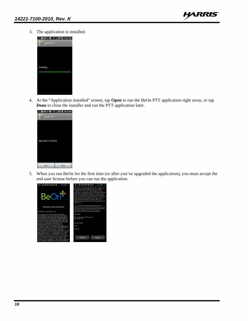
3. The application is installed.
4. At the “Application installed” screen, tap Open to run the BeOn PTT application right away, or tap
Done to close the installer and run the PTT application later.
5. When you run BeOn for the first time (or after you’ve upgraded the application), you must accept the
end user license before you can run the application.
14221-7100-2010, Rev. K
19
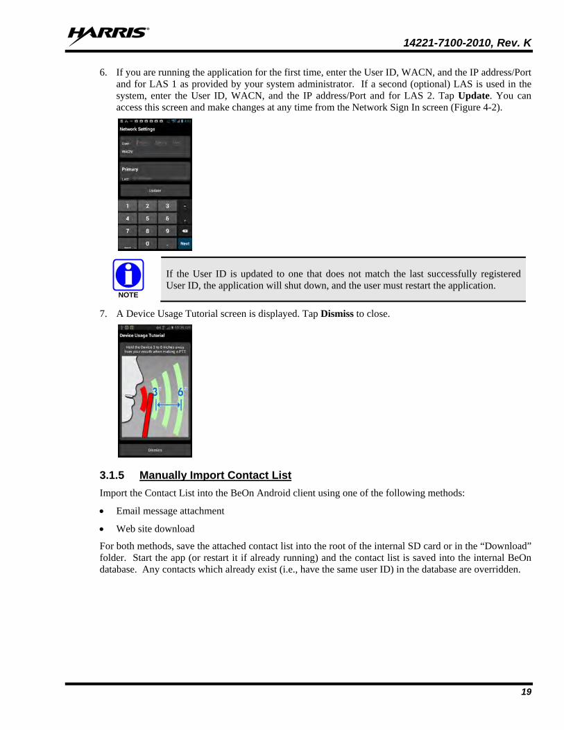
6. If you are running the application for the first time, enter the User ID, WACN, and the IP address/Port and for LAS 1 as provided by your system administrator. If a second (optional) LAS is used in the system, enter the User ID, WACN, and the IP address/Port and for LAS 2. Tap Update. You can access this screen and make changes at any time from the Network Sign In screen (Figure 4-2).
If the User ID is updated to one that does not match the last successfully registered User ID, the application will shut down, and the user must restart the application.
7. A Device Usage Tutorial screen is displayed. Tap Dismiss to close.
3.1.5 Manually Import Contact List Import the Contact List into the BeOn Android client using one of the following methods:
• Email message attachment
• Web site download
For both methods, save the attached contact list into the root of the internal SD card or in the “Download” folder. Start the app (or restart it if already running) and the contact list is saved into the internal BeOn database. Any contacts which already exist (i.e., have the same user ID) in the database are overridden.
NOTE

14221-7100-2010, Rev. K
20
3.2 BEON IOS CLIENT
3.2.1 Installation The BeOn application can be downloaded and installed directly from the Apple App Store, in the same manner as any other iPhone/iPad application. The App name in the Apple App store is “BeOn PTT" and the App Developer is "Harris Corporation.”
Beginning with the 3.0.1 release, BeOn iOS is delivered as a single application, supporting encrypted and unencrypted voice. Prior to upgrading from the AES version of BeOn, uninstall the existing “BeOn AES” application. The following “BeOn AES” data will be lost: • Network settings • Saved Password • Call History and recorded calls • Text Messages • Emergency Events • Contacts • User Preference settings; e.g., Call Settings Upgrading from the existing “BeOn PTT” application will preserve user data.
3.2.2 Manually Import Contact List Import the Contact List into the BeOn iOS client using one of the following methods:
• Import a Contact List attached to an email message. The email is opened using the built-in mail application. Select the email attachment and then select Open in BeOn PTT.
• Import a Contact List from a Web site. On the Web site, select the Contact List file and select Open in “BeOn PTT.”
3.3 BEON WINDOWS CLIENT (BWC)
3.3.1 Installation
It is highly recommended that any previous installation of the BeOn Windows Client is uninstalled before installing a newer version. Data files are not removed during the uninstall process and can be used by the newer version.
The application installation file is named BeOnClient.exe. Depending on the system installation, this file may be available via CD, URL, or other means. In any case, execute the install program as you would any other Windows application.
In order to install the BeOn Windows Client properly, you must have administrative rights for the PC on which the application is being installed. On Enterprise machines, this may require the use of 3rd party application to elevate rights. On a non-domain machine, Windows will ask if you want to elevate rights, to which you should respond “Yes.” You may be prompted to enter your password. Additionally, for an “All Users” installation, individual users must have access to write to the %PROGRAMDATA% directory while the application is running.
NOTE
NOTE
NOTE

14221-7100-2010, Rev. K
21
1. Once launched, the installer displays the following window:
2. Click Next to continue. The following Window appears:
3. Click I Agree to accept the license agreement. The following window appears:

14221-7100-2010, Rev. K
22
4. Select whether to install for all users or the current user. Click Next and the following window appears:
5. The first three components (the application, Java, and the Start Menu shortcuts) are required. The
Desktop Shortcut is optional. Click Next and the following window appears:
6. By default, the application is installed in the %PROGRAMFILES(x86)%\BeOn\Client directory
when installed for “All Users,” and in the %LOCALAPPDATA%\BeOn\Client directory when installed for a single user. Changing the installation directory is possible, but not recommended. Click Install and the following window appears:
7. If there are any errors, they show up in the window. Click Close to complete the installation.

14221-7100-2010, Rev. K
23
The directories where data is stored have changed with version R2D. When upgrading from R2C or earlier to R2D or later, data directories must be manually moved to preserve user data if desired. If an “only for me” installation was performed, copy all files from: %PROGRAMDATA%\BeOn\Client to %USERPROFILE%\BeOn\Client. Otherwise, if an “all users” installation was performed, copy all subdirectories from: %USERPROFILE%\BeOn\Client to %PROGRAMDATA%\BeOn\Client.
8. The BeOn Windows Client is now ready to run and is available in the Start Menu:
9. The BeOn Windows Client can be uninstalled by running the Uninstall BeOn Client application in
the BeOn folder of the Start Menu, or through the “Program and Features” option of the Windows Control Panel.
10. The BeOn Windows Client uses a couple of directories to store program files and application data. The application installation directory is:
• %PROGRAMFILES(x86)%\BeOn\Client (for “All Users” installation)
or
• %LOCALAPPDATA%\BeOn\Client (for single user installation)
All third party software, including the Java SE Runtime Environment, is also installed in this directory. There are no other third party applications or frameworks installed outside of this directory.
The application data directories are:
• %PROGRAMDATA%\BeOn\Client (for “All Users” installation)
• %USERPROFILE%\BeOn\Client (for single user installation)
NOTE

14221-7100-2010, Rev. K
24
The BeOn Windows Client also uses Windows Registry keys to store information about the installation. This information is used for re-installation and uninstallation. The registry keys for an “All Users” installation on a 64-bit machine are:
• HKEY_LOCAL_MACHINE\SOFTWARE\Wow6432Node\BeOn\Client
• HKEY_LOCAL_MACHINE\SOFTWARE\Wow6432Node\Microsoft\Windows\CurrentVersion\Uninstall\BeOn
The registry keys for an “All Users” installation on a 32-bit machine are:
• HKEY_LOCAL_MACHINE\SOFTWARE\BeOn\Client
• HKEY_LOCAL_MACHINE\SOFTWARE\Microsoft\Windows\CurrentVersion\Uninstall\BeOn
The registry keys for a single user installation (32- or 64-bit machine) are:
• HKEY_CURRENT_USER\Software\BeOn\Client
• HKEY_CURRENT_USER\Software\Microsoft\Windows\CurrentVersion\Uninstall\BeOn
11. The first time you run the BWC, specify a username and password. Check Remember Me if you want the application to remember your username and password. This dialog can also be accessed from the Login dialog (see Figure 6-1) and allows you to create a new user. The BWC supports multiple users, but only one user may be logged in at a time.
The password must be eight characters or less. If the password is more than eight characters, you will receive an error stating that “The Password is invalid.” This password provides “application lock” protection. It is NOT the VIDA network password.
Figure 3-3: Setup: Specify Username and Password
12. Enter the User ID, WACN, Password, and the IP address/Port and for the Primary LAS as provided by your system administrator. If a secondary (optional) LAS is used in the system, enter the IP address/Port. Click Next. You can change this any time from the Edit Settings dialog (see Section 6.2.1.5) or from the BeOn Client Login dialog (see Figure 6-1).
Ensure the proper firewall port settings are in place on the IP network to allow BeOn traffic to pass.
NOTE
CAUTION

14221-7100-2010, Rev. K
25
Figure 3-4: Setup: Network Settings
13. Enter your location information, if known. Click Next.
Figure 3-5: Setup: Location
14. A dialog is displayed allowing you to confirm your configuration information. If everything is correct, click Finish. If something is incorrect, click Back and make corrections as necessary.
Figure 3-6: Verify Client Configuration
3.3.2 Manually Import Contact List To import contacts into the BeOn Windows Client:
1. Click the Load Contacts button on the Contacts tab (see Section 6.2.5).
2. Browse to the contact list file “beonusers.txt.”

14221-7100-2010, Rev. K
26
3. Click Open.
• When the BeOn Windows Client is started (or restarted), it will detect the “beonusers.txt” file, read the file line by line, and enter a contact into its database for each user found in the file. If a contact with the same User ID (i.e., the combination of WACN, Region, Agency, and User) already exists in the database, the contact is not overwritten. This lets users customize the appearance of imported contacts.
• After a successful import, the contact list file is deleted and the BeOn Windows Client continues to start normally. If the import is unsuccessful, the user is notified and the contacts file left intact. The notification includes the line number of the beonusers.txt file where the error occurred.
3.4 LICENSE SERVER The first BeOn User ID to register is licensed in the License Server with a device identifier. If a user on a different device attempts to login with that same User ID, the user will get a “License exceeded error” message.
If the License Server is down, the user might receive a message stating “Connection Error.”
If a newer (e.g., R3A/R4A) BeOn PTT application registers with an older LAP version (e.g., R2B/R2C/R2D), a “Connection Error” occurs because the older LAP cannot process the newer protocol version presented to it by the UE.
NOTE
NOTE

14221-7100-2010, Rev. K
27
4. ANDROID CLIENT 4.1 START UP AND SIGN IN PROCEDURES
If a BeOn-enabled smartphone is plugged into a computer via USB and “USB Connection Mode” is enabled, the BeOn application cannot function. This is due to the storage required by the BeOn Group Communications application being unavailable for use while in “USB Connection Mode.”
1. Start the BeOn application software by tapping the BeOn PTT option from the phone’s main display. The application proceeds to:
• The Network Sign In screen (Figure 4-2) if Application lock is set to “No Lock” in the settings menu (see Section 4.4.9).
Or
• The PIN entry screen (Figure 4-1) if Application lock is set to PIN Lock in the Settings menu (see Section 4.4.9). There is no limit on login attempts and the user will not be locked out if the PIN is entered incorrectly. After correctly entering the PIN, the Network Sign In screen is displayed.
Figure 4-1: PIN Entry Screen
Figure 4-2: BeOn Application Login
2. On the Network Sign In screen, tap Network Config if you need to make any changes to the User ID, WACN, or LAS 1/LAS 2. Tap the “i” icon to display the About screen.
3. Enter your password. Each character of the password is displayed briefly as it is typed. Contact your System Administrator if you have forgotten your password.
4. Tap Save Password to skip this step in the future. Press Sign In when finished.
5. “Registering” is displayed on the screen during sign in, and “Updating Personality” is displayed while user information is updated from the system (if applicable).
NOTE

14221-7100-2010, Rev. K
28
4.1.1 Registration and Provisioning After the user taps Sign In, the following steps are taken by the application:
1. Registration with BeOn Access Server is attempted.
2. Processing of provisioning information is performed (if necessary).
3. Establishment of current scanning parameters is performed.
As the application proceeds with these phases, feedback to the user continues with each step and access to the underlying main window is prevented until the scanning information has been received, processed, and displayed where appropriate.
4.1.2 Device Controls If the BeOn enabled device has a dedicated PTT button, this is can be used for PTT operations. The volume down button can also be used as the PTT button.
The volume up button can be used to declare a distress.
For a description of all other device controls, refer to the manufacturer’s documentation for your device.
4.1.3 Phone and PTT Call Interoperability This feature focuses on ensuring that standard phone calls interoperate with PTT communications in BeOn in a straightforward way. Some cellular networks support simultaneous voice (standard phone calls) and data communications (PTT communications), and others do not, so the BeOn user must be prompted to properly handle standard voice calls as they appear, and PTT communications must be treated according to the user’s demands.
If standard phone calls and PTT calls can be supported simultaneously, the user can release the PTT button when a standard phone call arrives. Conversely, if the user is making a standard phone call, and a PTT call is received, the standard phone call continues uninterrupted and the PTT call is recorded but not played.
For cells that support simultaneous voice and data:
• If a PTT call is received during an ongoing circuit switched call: BeOn does not play any sound unless the call is a distress call; then BeOn plays the normal
distress tone. BeOn gives a visual indication as it normally does for an incoming PTT. The PTT call is recorded. When the circuit switched call is over, the user hears the PTT call if it’s still in progress. The user can go back and replay the missed PTT call at any time after the circuit switched call is
done.
• If a circuit switch call is received during an ongoing PTT call: The PTT call is interrupted once the Phone app is brought to the foreground. BeOn continues to record the PTT call but does not play it. When the circuit switched call is over, the user hears the PTT call if it is still in progress. The user can replay the missed PTT call at any time after the circuit switched call is done. If the user ignores or dismisses the circuit switched call, the PTT call continues to play if it is still
in progress.

14221-7100-2010, Rev. K
29
Some networks still have cells that do not support simultaneous voice and data; for example, some EDGE cells:
• If a PTT call is received during an ongoing circuit switched call: The data connection to BeOn is suspended, no information about the PTT call is received, and
BeOn is unaware of the PTT call. Nothing is recorded in the history tab. When the circuit switched call is over, the user hears the PTT call if it is still in progress. BeOn
records the portion of the PTT call that occurs after the circuit switched call ends.
• If a circuit switch call is received during an ongoing PTT call: Once the phone switches over to the Phone app, BeOn stops playing and recording the current
PTT call. During the circuit switched call, the data connection to BeOn is suspended, no information about
incoming PTT calls is received, and BeOn is unaware of any PTT calls. Nothing is recorded in the history tab.
When the circuit switched call is over, the user hears the PTT call if it is still in progress. BeOn records the portion of the PTT call that occurs after the circuit switched call ends.
If the user ignores or dismisses the circuit switched call, the PTT call continues to play if it is still in progress.
4.2 ALERT TONES Refer to Table 4-1, Table 4-2, and Figure 4-3 for the tones associated with the BeOn application.
Table 4-1: BeOn Alert Tones
NAME DESCRIPTION
Call Queued 1 short low-frequency tone followed by two short high-frequency tones. Indicates the call is queued and will be granted later.
Call Denied 3 short mid-frequency tones. Indicates the radio is out of coverage or group is active. Grant 1 short mid-frequency tone. After pressing the PTT button, indicates that it is ok to talk.
Call Removed 1 long low-frequency tone. Notifies the user that their current call has been rejected or has failed.
Incoming Distress 3 short high-frequency tones. Sounds when the user receives a distress on a scanned group.
Incoming Call On Selected Group 2 short low-frequency tones.
Incoming Call On Scanned Group 2 short high-frequency tones.
Incoming Individual Call 1 long high-frequency tone.
No Key Loaded 6 short mid-frequency tones. Sounds during encrypted groups/individual calls if no key is loaded.
Table 4-2: Tone Frequencies and Durations
Name Frequency Name Duration
Low 800 Hz Short 50 msec. Mid 1400 Hz Medium 100 msec. High 1800 Hz Long 150 msec.

14221-7100-2010, Rev. K
30
Duration Indicated in msec
Incoming Individual Call
150
Incoming Call on Scanned Group
Incoming Distress Call
50 50 50
Incoming Call on Selected Group
50 50
Call Removed
150
Call Denied
50 50 50
Call Queued
50 50 50
Grant
50
50 50
Off800 Hz
1400 Hz1800 Hz
Figure 4-3: Alert Tones
4.3 BLUETOOTH OPERATION The BeOn Android app supports use of the Harris Covert Bluetooth Microphone (product number 12082-0684-01). When the phone is paired with this microphone, users can transmit and receive calls using Bluetooth.
Please refer to the Harris Covert Bluetooth Microphone User Manual (14221-1600-2040) for more information.
Essential operation of the Covert Bluetooth Microphone requires one additional step beyond the pairing of the microphone in Android Bluetooth settings. The “Media audio” option in Android Bluetooth settings for the “Harris” pairing must NOT be checked. This allows the BeOn app to correctly connect and maintain the connection to the Covert Bluetooth Microphone.
NOTE

14221-7100-2010, Rev. K
31
4.3.1 Configuration Perform the following to configure the Android BeOn client to use the Covert Bluetooth Microphone:
1. In the Android settings, enable Bluetooth.
2. Turn the Covert Bluetooth Microphone on and initiate pairing by pressing and holding the power
button until the light blinks blue and red. Select the “Harris” device from the list once it appears.
3. The light on the Covert Bluetooth Microphone blinks blue when the mic is connected to the phone.
4. Tap the gear icon next to the Harris entry.
5. Make sure the “Media audio” option is NOT checked.

14221-7100-2010, Rev. K
32
6. In the BeOn PTT app, select Preferences from the application menu and scroll down to the “Bluetooth Settings” section. Make sure the “Use Bluetooth” option is checked.
7. The Covert Bluetooth Mic shows a steady blue light when connected and ready to use with BeOn.
4.3.2 Covert Operation With BeOn on Android cell phones, users may plug ear buds with a built-in wired microphone into the phone and use the covert device as a PTT and emergency remote control. Users appear to be listening to music or participating in a phone call but are in full communications with their talkgroup.
For covert operation:
1. From the BeOn main menu, select Bluetooth Audio. This option is only available if Bluetooth is enabled on the phone and a Covert Bluetooth microphone is paired with the phone.
2. One of the following screens is displayed:

14221-7100-2010, Rev. K
33
• Bluetooth Audio is always available and allows incoming audio to be played by the covert microphone.
• Covert operation can be achieved by choosing the Wired Headset option. This option is available if a wired headset is plugged into the phone. When selected, audio is sent to the headset/ear buds that are plugged into the phone, and outgoing calls are captured by the ear bud microphone if present.
• If no wired headset is plugged into the phone, Phone Speaker is available. When selected, audio is played out of the phone’s external speaker.
4.4 USER INTERFACE
4.4.1 Main Display Figure 4-4 is a sample Android BeOn display. The top of the display hosts the distress button, the BeOn logo (registration status), and presence button. A colorful BeOn indicates the application is registered with the system; a non-colorful logo indicates the application is not registered with the system. The bottom of the display hosts the Status Bar (see Section 4.4.2 for more information).
The BeOn application features a tabbed user interface that allows users to quickly access key features:
• The Home tab is displayed when the application starts and hosts the map (see Section 4.4.4). • The Groups tab displays the configured talk groups (see Section 4.4.4.1). • The Contacts screen displays all of the contacts in the PTT address book (see Section 4.4.6). • The History tab lists all incoming and outgoing calls, conversations, text messages, location (GPS)
requests, distress initiations, and distress cancellations (see Section 4.4.7). • The Profiles tab displays available profiles (see Section 4.4.8).
Figure 4-4: BeOn Sample User Interface

14221-7100-2010, Rev. K
34
4.4.2 Status Bar The bottom of the display, or Status Bar, acts as an on-screen PTT button by default. This can be changed in the Settings menu (see Section 4.4.9). The Status Bar also displays the group or user currently selected for the next call when PTT is pressed, as well as the last call transmitted or received. Adjust the volume by tapping the speaker icon . The encryption lock icon ( ) displays above the speaker icon when the next call target is a group configured for encryption. If the lock icon has a line through it ( ), the next call target is a group that should be configured for encryption but has no key present to allow for encrypted communications.
The color of the Status Bar changes based on the current activity: • Blue background indicates “Idle” mode (i.e., no active call). • Yellow background indicates outgoing calls. • Green background indicates incoming calls. • Red background indicates “distress” mode.
When idle, the left side of the Status bar is a tappable area that displays groups that are in distress. When distress calls are placed or received and the user is also in distress, the entire call status area has a red background.
4.4.3 Adjust Volume 1. Tap the speaker icon in the Status Bar.
2. Drag the slider to the desired volume level and tap Close.
4.4.4 Home The Home tab is displayed when the application starts and hosts the map. The map defaults to showing members of the currently selected group on the map. The map is centered on the location of your device; other members may not be visible on the map. The following sections describe the mapping feature in detail.
Figure 4-5: Home Tab

14221-7100-2010, Rev. K
35
4.4.4.1 Geographic Mapping BeOn utilizes Google Maps™ as part of its situational awareness capability. There are small indicators in each corner of the map that provide information or change the map’s focus when touched:
Lists the watched users that haven’t provided their location to the system.
Lists the watched users that have provided GPS coordinates and allows for users to be shown/hidden independently.
Re-zooms the map to allow all users on the map to be within the current viewable area.
Re-zooms the map to make the current user the central focal point.
Enables street view when user taps and drags this icon to a desired street location; streets on the map which support this feature are highlighted in blue.
Wherever possible, User IDs are displayed as descriptive alias names if the User ID has a contact entry. When a VPS (Status Aware) is available in the system, the BeOn client receives information about the type of equipment an individual is carrying (e.g., BeOn, LMR, etc.). This affects the displayed icon.
Four map options are available. Select the desired view from the Layer and Assets menu, accessed by tapping the right-hand tab (see Figure 4-6).
• Streets - displays the default road map view
• Hybrid - displays a mixture of normal and satellite views
• Satellite - displays Google Earth™ satellite images
• Physical - displays a physical map based on terrain information
Figure 4-6: Access the Layer and Asset Menu

14221-7100-2010, Rev. K
36
4.4.4.2 Call Indications If the Map is displayed during a call and the person making the call is visible on the map, the user’s icon has a blinking radio wave icon around it during the entire call. The radio wave is blue during normal calls and red during distress calls.
Figure 4-7: Normal Call Indication
Figure 4-8: Distress Call Indication
4.4.4.3 Smart Location Update
The Smart Location Update feature allows the user to configure time and distance intervals to settings which could be detrimental to the device’s battery life if values are used with very short elapsed time or distance between location updates. Each location update requires power from GPS, Wi-Fi, Cell, and other radios.
Maps are updated when notified by the phone that the location has changed. The Smart Location Update feature allows the user to specify the frequency of location updates sent to the network. The VNIC presence service provides location updates to subscribers in the same enterprise/agency. Smart Location Update parameters are configured via the Settings menu (see Section 4.4.9).
The Time interval, Distance interval, and Maximum update frequency parameters are selectable even if Smart Location Update is disabled. These parameters are used for normal location requests for local use. When Smart Location Update is disabled, location updates are only sent to the network in the following circumstances:
• Initiation of a Group Call, Individual Call, or Distress Call.
• With Text Messages.
• When sending SDS acknowledgements in response to location queries.
• With presence state changes.
CAUTION

14221-7100-2010, Rev. K
37
4.4.4.4 Tracking Users and Groups The BeOn Android application allows the tracking of up to 38 contacts OR a single group with up to 38 of its registered users.
1. Open the Layer and Assets menu (see Figure 4-6).
2. Select Map Groups or Map Contacts.
• Map Contacts is disabled if no contacts exist.
• If the currently tracked entity is a group and you select Map Contacts, a warning is displayed. This makes the user aware that the currently tracked group will be removed from the map. This warning is only displayed once.
• If the currently tracked entity is a contact and you select Map Group, a warning is displayed.
This makes the user aware that the currently tracked content will be removed from the map. This warning is only displayed once.
3. Check the contacts or group that you want to map (up to 38 contacts OR a single group with up to 38 of its registered users can be mapped). If no group/contacts are selected, only self is mapped.
4. Tap OK to map the selected users/group, tap Clear All to clear all selected, or tap Cancel to close the selection dialog.
4.4.4.5 Hiding/Unhiding Mapped Contacts
1. Tap to display watched users that have provided GPS coordinates and are on the map.
2. Uncheck a contact to hide it on the map. The BeOn device is still subscribed for the contacts presence and location updates, but the contact is not visible on the map.
3. Check a contact on the list to display it on the map.

14221-7100-2010, Rev. K
38
4.4.4.6 Free-Form Map Navigation A new option on the mapping slider offers the ability to allow for no group or self-centered orientation of the map. By default, the map will keep the next call group members on the map within the view of the user, but this new option allows the user to pan and zoom around in the map freely without snapping back to the group or self view.
There are 2 modes for this option:
Option is disabled; map will zoom to group or self whenever a presence or location update occurs.
Option is enabled; user can pan and zoom freely.
4.4.5 Groups Tap the Groups tab to view the configured talk groups. Tapping one of the group rows selects the talk group. Selecting a new group updates the Status bar for the next PTT.
Figure 4-9: Groups Tab
Tap and hold on the group row to open a context menu. The choices allow the BeOn user to see other registered users in the talk group, send a group text, or review the call history for a talk group.
Figure 4-10: Group
Context Menu

14221-7100-2010, Rev. K
39
• Show Group Members displays the individuals that make up the group. There is a row entry for each group member showing the presence icon, member name, supervisor status, and the VIDA ID.
The title row shows the group name with a count of how many members are in the group. This is the count of registered members listed. The list is restricted to no more than approximately 40 users due to system limitations. The member details provided is determined by the VNIC.
Figure 4-11: Group
Members
• Send Group Text allows text messaging to groups. See Section 4.5.5.
• Call History displays the call history for that group.
4.4.6 Contacts The Contacts screen contains one entry for each of the contacts in the PTT address book. If the list is longer than the screen allows, a scroll bar appears. The first and last name, VIDA user ID, display name, and current presence (if applicable) of each contact is displayed. Refer to Table 2-3 for a description of the icons displayed for each contact.
Figure 4-12: Contacts
Tab

14221-7100-2010, Rev. K
40
4.4.6.1 Add a New Contact 1. While on the Contacts tab, press the phone’s Menu button and tap Add
Contact.
2. Enter the contact’s name and the Region, Agency, and User information.
3. Tap Add Contact.

14221-7100-2010, Rev. K
41
4.4.6.2 Delete All Contacts While on the Contacts tab, press the phone’s Menu button and tap Delete All Contacts.
4.4.6.3 Contacts Context Menu Tap and hold anywhere on the contact row to open a context menu.
The user has the following options:
• Next Call: Causes that contact list entry to be selected for an individual call. This has the same effect as a short tap on the contact entry on the main contacts list.
• Get Presence: Retrieves the current presence state of the contact. The presence icon, displayed to the left of the first name, is updated according to the presence state.
• Send Text: Sends a text message to the selected contact.
• Message History: Views message history of this contact.
• Modify Contact: After selecting this option, the user can edit the name and/or phone number of the currently selected contact.
• Delete Contact: Permanently deletes the selected contact after prompting the user to confirm the delete.
Figure 4-13: Contacts
Context Menu

14221-7100-2010, Rev. K
42
4.4.7 History Tab The History tab (Figure 4-14) lists incoming and outgoing calls, conversations, text messages, location (GPS) requests, distress initiations, and distress cancellations. Up to 200 audio-based events and up to 250 total events (including text messages, distress initiations/cancellations) can be stored in the history. After reaching 200, new events will overwrite existing events, starting with the oldest first.
Tap the playback icon for an event to play back its audio. Tap to stop playback of that audio. Tap the event to display details for that event; tap and hold an event to display additional options.
Figure 4-14: History Tab
Tap an event to open the View Call Details window. The information displayed differs depending on the type of call. Call details can include the speaker, call recipient, call time, and location.
Tap and hold an event to open the context menu. Options available differ depending on the type of call.
• Next Call: Makes the contact the target for the next PTT.
• Get Presence: Retrieves the current presence state of the contact. An Android notification is created to inform the user of the resulting presence, and that contact’s presence information in the Contacts tab is updated with this information.
• Modify Contact: After selecting this option, the user can edit the name and/or VIDA user ID of the currently selected contact.
• Call History: Displays a list of calls in which the selected user/group is involved.
• Delete: Deletes the selected event.

14221-7100-2010, Rev. K
43
4.4.8 Profiles View available profiles from the Profiles tab. Every BeOn subscriber has a personality which can contain up to 16 profiles. Profiles allow the BeOn subscriber to quickly change the organization associations of the device for different roles, activities, or regional communications. Each profile can contain up to 16 groups. When a profile becomes the ‘active’ profile, the device scans all groups contained in that profile. A check mark indicates the ‘active’ profile. Only one profile is active at a time.
Each profile is characterized by the following:
• Can contain 0 or 1 Scan Priority 1 (P1) group
• Can contain 0 or 1 Scan Priority 2 (P2) group
• Can contain 0 to 16 Scan Priority 3 (P3) groups
• Distress behavior: None - distresses are not permitted. Current Group, User Clears - Distress initiated for self and on
current group, user must clear the distress. Current Group - Distress initiated on current group. Fixed Group - Distress initiated for self and on fixed group (set by
agency administrator), user must clear the distress. Fixed Group - Distress initiated on fixed group (set by agency
administrator).
• Supervisor flag for each group in the profile.
A user can change the ‘selected’ group of an active profile by choosing a different group to be the Target or ‘Next Call.’ Selecting an individual contact as ‘Next Call’ does not have any effect on the active profile.
To view the details of a Profile, tap and hold the Profile row and tap View Profile. “Supervisor” displayed to the right of the group name indicates that the user has supervisory privileges for that group. Supervisor privileges for a group mean that the user can:
• Cancel group distress for that group.
• Preempt calls made by other users with non-supervisory privileges when initiating a call on that group.
Figure 4-15: Profiles Tab

14221-7100-2010, Rev. K
44
4.4.9 Settings To access the Settings Menu, press the phone’s Menu button and tap Preferences.
4.4.9.1 General Settings • Network sign in automatically.
• Start BeOn on startup.
• Override silent mode: If checked, the user can listen to incoming call audio even when the phone is in silent mode as long as the user’s Presence is set to “Available.” If unchecked (default), when the phone is set to silent or vibrate, then the BeOn user’s presence is also set to silent. When the phone is unmuted, then the BeOn user’s presence is restored to what it was before the phone was muted.
• Network Settings - Opens the Network Settings dialog.
Figure 4-16: Network Settings
4.4.9.2 Calls Settings • Play audible grant tone - When the user presses the PTT button, an audible sound is generated once
the call is initiated and the user is free to speak.
• Turn on Talk Back timer - When checked, after receiving a call, the caller (Individual or Group) is temporarily assigned as the Next Call for 10 seconds (a timer counts down in the lower left of the screen). This allows the user to return the call within 10 seconds. The Talk Back timer will not show the countdown if the Next Call already displays the same group/user as the incoming call.

14221-7100-2010, Rev. K
45
• Talk Back Timer - Duration in seconds of the Talk Back timer (see previous setting). Default is 10 seconds, and acceptable values are 1 to 60. When the “Turn on Talk Back timer” setting is unchecked, this setting is disabled.
• Conversation Timeout - Group and individual calls are consolidated into conversation entries in the History tab based on this value. Calls made after this time expires are not grouped in the conversation, but instead cause another event entry to be created.
4.4.9.3 Text Message Settings
• Enable read receipt - Check this option to receive a confirmation that the text message recipient read the message.
• Play tone on receipt - When checked, the device plays an audible tone when a text message is received.
4.4.9.4 Smart Location Updates
• Enable smart location - Check this option to enable smart location. When smart location is enabled, the BeOn subscriber device updates its location every x minutes (Time Interval) or y meters (Distance Interval), whichever happens first but no more than z seconds (Max Update Frequency).
• Time interval - Specify the time interval at which the subscriber device will update its location. Range: 10 seconds to 1 hour in second intervals. Default: 5 minutes.
• Accuracy - Determines how accurate the location reading is. Options include: High (1 meter), Medium (100 meters) - default, Low (10 kilometers), and Off. When Off is selected, the BeOn application will not ask Android for location updates, but location updates may be given to the BeOn application if other apps are expressing an interest in location.
The “High (1 meter)” option allows for very accurate location but consumes a large amount of battery power. The “Medium (100 meters)” option is relatively accurate but consumes a smaller amount of battery to function. The “Low (10 kilometers)”option consumes the least battery power.
• Max update frequency - Range: 1 sec to 1 hour in second increments. Default: 30 seconds.
• Distance Units - Specify the units (Metric or English) used for “Distance interval.”
• Location timeout - Specify the time which should elapse before BeOn considers the location of users on the map to be too old or stale. Range: 30 to 9,999 seconds. Default: 5 minutes.
4.4.9.5 Security Application lock - Allows the BeOn application to be locked, requiring a PIN to use the application. The PIN does not have to match any user password in the VIDA system and can consist of a number ranging from 4 digits to 16 digits. Default: No Lock.
4.4.9.6 Security Settings
• Zeroize - Removes all encryption keys.
• Reset message numbers - Resets message numbers to zero.
• Request rekey - Requests a rekey from the KMF (OTAR).
• Secure mode - Check to enable encryption; uncheck to disable encryption.
CAUTION

14221-7100-2010, Rev. K
46
• Security key details - Displays OTAR Enabled status, KMF Status, provisioned Storage Location Number (SLN) bindings and key presence.
OTAR Enabled: Yes = RSI from the UAS matches the RSI included in the ukek file. No = RSIs do not match (could be an RSI=0 problem; do a force update).
KMF Status: Configured = KMF IP address is present. Not Configured = App does not have KMF IP address. Registered = KMF has completed registration process with client. Unregistered = Client has not registered with the KMF.
4.4.9.7 Bluetooth Settings Use Bluetooth - Enable/Disable Bluetooth.
BeOn supports the Harris Covert Bluetooth Microphone which provides PTT and distress functionality. BeOn also works with off-the-shelf Bluetooth devices, but may have limited functionality.
4.4.9.8 Power Power Mode - Select one of the following options for Power Mode:
• Optimal Battery Life (default) - Causes the BeOn application to limit its network transmissions between PTT calls. This option results in slightly slower response times to the first PTT following an extended idle time.
• Best Performance - Keeps the network connection in a reliable state, so that PTT calls after extended periods of time are quick to respond; this option causes the PTT application to send more network transmissions and wears down the battery faster than the Optimal Battery Life option.
4.4.9.9 Audio Calibration Audio Playback Calibration - Displays screen allowing the user to adjust the phone speaker volume gain for incoming audio. User can tap “Play Test Audio” and adjust the slider to adjust the volume of the audio as it is being played. This setting affects the volume of all incoming PTT calls. Tap Save to save the setting, or reset to avoid changing the setting after having adjusted it.
4.4.9.10 Logging Send Logs - Allows the user to send BeOn internal debug logs via email to the Harris BeOn development team for investigation of issues as they arise. Once “Send Logs” is selected, a list of email providers is displayed to the user. Select the email provider to use. The email form that appears has the individual debug files attached.
4.4.9.11 About
• About - displays information about the BeOn installation.
• Device Usage Tutorial - displays an informational screen showing the user the appropriate distance the phone should be held from the face for best PTT experience.
NOTE

14221-7100-2010, Rev. K
47
• License Agreement - displays the End User License Agreement.
4.5 USING THE SOFTWARE
4.5.1 Group Calls
4.5.1.1 Transmit to a Group 1. Select a call record from the History tab (Section 4.4.7), or select a group from the Groups tab
(Section 4.4.3). The last selected Group or Contact name always appears in the Status bar (see Figure 4-4).
2. Press PTT and begin speaking. PTT button will vary depending on configuration, but the default PTT is the Status bar. When transmitting, the Status bar is yellow.
3. When finished, release PTT.
4.5.1.2 Incoming Group Calls During an incoming group call, the Status bar is green and displays the Caller ID. After the talk spurt ends, the call log is updated. The Status window is cleared after approximately two seconds.
If the Talkback Timer is enabled in the Settings menu (Section 4.4.9) and a call is initiated on a scanned group, not your default group, the group’s name is displayed as the next call with a timer counting down. Press the PTT button before the timer expires to respond to the group. When the timer expires, the Next Call displayed returns to the default group.
4.5.2 Individual Calls
4.5.2.1 Transmit to an Individual Pre-Stored or Received Individual Calls
1. Select the Contact from the History tab or select the Contacts tab.
2. Tap a contact from the list to make it the next call.
3. Press PTT to initiate the call. Call information is displayed in the Status window.
Direct Dial an Individual
1. Press the phone’s Menu button.
2. Tap Individual Call.

14221-7100-2010, Rev. K
48
3. Enter the User ID and tap OK.
4. Press PTT to initiate the call. If the dialed number is in the Contact list, the
alias is displayed. Call information is displayed in the Status Bar.
4.5.2.2 Incoming Individual Calls During an incoming individual call, the status bar is green and displays the Caller Alias, and/or VIDA ID, depending on what information is currently available.
Figure 4-17: Incoming Individual Call
4.5.3 Ignore a Call Incoming group and individual calls can be ignored by tapping . Once a group is ignored, calls from that group are not received until the group call has ended and the call’s hang timer has expired. If the user places a PTT call on that group, even during the hang timer countdown, the call is placed and the group is no longer ignored. Calls cannot be ignored while the user is in a local distress.
4.5.4 Conversations Group and individual calls are consolidated into conversation entries in the History tab based on the Conversation Timeout value in Call Settings (Section 4.4.9). If any call is either placed or received and its source (group or individual) matches the last call placed or received, the previous and current calls are placed into a conversation and the conversation entry is displayed in the History tab (see Section 4.4.7).

14221-7100-2010, Rev. K
49
Figure 4-18: Conversations
Tap to play the entire conversation. A tone is heard between each call (refer to Section 4.2). Once playback of a conversation has begun, tap to stop playback for that conversation. The individual calls in the conversation can be viewed by tapping the conversation entry in the History tab. The usual group and contact menus are available in the context menu, based on the source and destination of the conversation. Tap Delete to delete the conversation and all the calls associated with it.
4.5.5 Sending a Text Message 1. From the Contacts tab or the Group Members screen, tap and
hold on an entity to open the context menu. Tap Send Text. or From the Groups menu, tap and hold anywhere on a group row to open the sup-menu. Tap Send Group Text.
2. Enter a message, up to 214 characters, and tap Send Text.
Depending on system configuration, the following Report Type options may be available when sending a group text:
• None - No receipt required.
• One recipient - The originator receives a receipt if at least one target device receives the message.
• Count recipients - The originating device receives a count of the acknowledgements received from the receiving devices until a timeout.

14221-7100-2010, Rev. K
50
4.5.6 Receiving a Text Message 1. in the top of the display indicates unread BeOn notifications;
i.e., text messages, distresses, etc.. Tap the icon and drag down.
2. Select the “Unread BeOn Notifications” option under Notifications.
3. Tap to read the text message.
4.5.7 Presence User and group presence services support the transmission of the status of users and groups to interested users.
Perform the following to set your presence options:
1. Tap the Presence icon (e.g., ).
2. Select the desired option:
• Available - The BeOn user is registered in the system.
• Silent - Indicates that the provider is not presently listening to PTT calls. The BeOn client records incoming calls during the Silent/Vibrate state, but plays neither received audio nor floor control tones.
• Agency specific states can also be set up by the System Administrator (for example, “In Transit” or “Out to Lunch”).
In addition to presence options available to the user, two more states are utilized by the system, but are considered automatic states:
• Busy - In systems that support simultaneous voice and packet data services, “Busy” reflects whether or not the provider is in a circuit switched call and is thereby temporarily unavailable to listen to or respond to PTT communications. In the Busy state, the BeOn client creates call-log records for all talk-spurts that were not played and records received audio. See the following note.

14221-7100-2010, Rev. K
51
• Unavailable - The BeOn user is not registered in the system. See the following note.
“Busy” and “Unavailable” cannot be set by the user; they are automatic states that kick in when the user is taking a circuit switch (normal phone) call and when they are not registered in the system, respectively.
Users can query the presence of other users to determine if they are available for BeOn group and individual calls (see Sections 4.4.6.3 and 4.4.7).
4.5.8 Scanning When a profile becomes ‘active,’ the device is scanning all the groups contained in that profile. Only one profile is active at a time. Refer to Section 4.4.8 for more information on profiles.
4.5.8.1 Scanning Priority When scanning is enabled, a higher priority incoming call overrides the receive audio of a lower priority incoming call.
The following lists the scan priority order from highest to lowest:
1. Distress call
2. Individual call
3. Priority 1 (P1) call
4. Priority 2 (P2) call
5. Priority 3 (P3) call
4.5.8.2 Disable Scanning When the scanning feature is disabled, only the selected group is monitored by the BeOn application.
To disable scanning, select “Disable Scanning” from the application context menu while displaying the Groups tab.
4.5.8.3 Enable Scanning When scanning is enabled, all groups in the currently active profile are monitored by the BeOn application.
To enable scanning, select “Enable Scanning” from the application context menu while displaying the Groups tab.
4.5.9 Distress Distress behavior is defined by the currently active profile. The following distress behaviors are supported:
• None.
• Distress alert only. The user must clear the alert.
There is no group state, only an individual state.
The declaring user can clear the individual distress state.
A console user can clear the individual state at the VNIC, but not the user’s local state.
NOTE

14221-7100-2010, Rev. K
52
• Distress alert and distress call on the default distress talk group. Tapping Cancel Distress clears both. The user must clear the alert locally.
The declaring user or console can clear the individual distress state on the network.
Only the declaring user can clear the local state.
An authorized entity such as a console, supervisor, or network management system can clear the group distress.
Declaring users who are authorized to clear group distresses can clear both the individual and group distress.
• Distress alert and distress call on the selected talk group. Tapping Cancel Distress clears both. The user must clear the alert locally.
The declaring user or console can clear the individual distress state on the network.
Only the declaring user can clear the local state.
An authorized entity such as a console, supervisor, or network management system can clear the group distress.
Declaring users who are authorized to clear group distresses can clear both the individual and group distress.
• Distress call on the default distress talk group. Tapping Cancel Distress clears the group distress.
An authorized entity such as a console, supervisor, or network management system can clear the group distress.
Declaring users who are authorized to clear group distresses can clear the group distress.
• Distress call on the selected talk group. Tapping Cancel Distress clears the group distress.
An authorized entity such as a console, supervisor, or network management system can clear the group distress.
Declaring users who are authorized to clear group distresses can clear the group distress.
4.5.10 Initiating a Distress 1. Press .
2. Confirm the distress at the prompt. The distress is initiated on the distress group which may be different than your currently selected group.
3. The Status bar is red during a distress. If the auto-key feature is enabled, an automatic PTT occurs for a configurable length of time following the initiation of a distress on a group. Pressing PTT during this time interrupts the auto-key timer.
Depending on the distress behavior defined by the system administrator, you may not be able to change the next call, profile, or scanning until the distress is cleared.
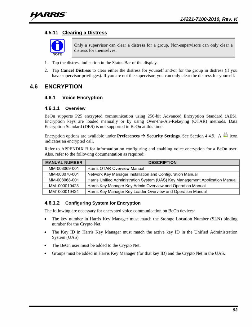
14221-7100-2010, Rev. K
53
4.5.11 Clearing a Distress
Only a supervisor can clear a distress for a group. Non-supervisors can only clear a distress for themselves.
1. Tap the distress indication in the Status Bar of the display.
2. Tap Cancel Distress to clear either the distress for yourself and/or for the group in distress (if you have supervisor privileges). If you are not the supervisor, you can only clear the distress for yourself.
4.6 ENCRYPTION
4.6.1 Voice Encryption
4.6.1.1 Overview BeOn supports P25 encrypted communication using 256-bit Advanced Encryption Standard (AES). Encryption keys are loaded manually or by using Over-the-Air-Rekeying (OTAR) methods. Data Encryption Standard (DES) is not supported in BeOn at this time.
Encryption options are available under Preferences Security Settings. See Section 4.4.9. A icon indicates an encrypted call.
Refer to APPENDIX B for information on configuring and enabling voice encryption for a BeOn user. Also, refer to the following documentation as required:
MANUAL NUMBER DESCRIPTION MM-008069-001 Harris OTAR Overview Manual MM-008070-001 Network Key Manager Installation and Configuration Manual MM-008068-001 Harris Unified Administration System (UAS) Key Management Application Manual MM1000019423 Harris Key Manager Key Admin Overview and Operation Manual MM1000019424 Harris Key Manager Key Loader Overview and Operation Manual
4.6.1.2 Configuring System for Encryption The following are necessary for encrypted voice communication on BeOn devices:
• The key number in Harris Key Manager must match the Storage Location Number (SLN) binding number for the Crypto Net.
• The Key ID in Harris Key Manager must match the active key ID in the Unified Administration System (UAS).
• The BeOn user must be added to the Crypto Net.
• Groups must be added in Harris Key Manager (for that key ID) and the Crypto Net in the UAS.
NOTE

14221-7100-2010, Rev. K
54
4.6.1.3 Group and Crypto Net Administration
The “Delete Key” operation on an End User in the “Manage Crypto Nets” section of the UAS is not supported in BeOn at this time. The user must use the “Zeroize” function in Preferences of the BeOn client application to remove key material.
In the UAS, define a Crypto Net that contains the users and groups targeted for encrypted communications.
• Users and groups must be added to the Crypto Net in order to participate in encrypted communications.
• Make a note of Crypto Net SLN and Active Key IDs.
• The SLN binding number must match the key number entered in the Key Admin tool.
• The Active Key ID in the UAS must match the Key ID in the Key Admin tool.
Refer to the Harris UAS Key Management Application manual (MM-008068-001) for instructions on how to configure a Crypto Net.
4.6.1.4 Distributed Key File Generation (.dkf) The Harris Key Manager tool allows entry of key information and export of that key information into a distributed key file (.dkf) that can then be added to the BeOn application to support encrypted voice communications.
• Groups targeted for encrypted communications must be added in the Harris Key Manager to allow for encrypted communications.
• The key number entered in the Harris Key Admin tool must match the key SLN binding number entered in the UAS.
• The Key IDs entered in the Key Admin tool must match the SLN binding number chosen in the UAS.
• The Key Admin tool can then be used to generate a .dkf for later import on the BeOn phone.
Refer to the Harris Key Manager Key Admin Overview and Operation manual (MM1000019423) for more information on how to enter key information and export keys to a .dkf file.
4.6.1.5 Manual Key Loading Once the Distribution Key File and SLN Binding Report information from the Crypto Officer (CO) has been obtained, follow these steps to load the keys into the BeOn application on the phone.
1. Enable USB storage on the BeOn PTT device to allow copying of files between the computer and the BeOn device’s SD card.
2. Transfer the key file to the BeOn device’s SD card and disable USB storage mode once the file is confirmed to have been transferred successfully. Refer to your phone’s documentation on how to disable USB storage mode, as this mode is adjusted differently from phone model to phone model.
3. Start the BeOn application. If a key file is detected in /mnt/sdcard, a list of available key files is displayed. Select the key file.
4. If the key file is encrypted using a 256-bit AES key derived from a password using RFC 2898, the user is prompted to enter a password; otherwise, the user is prompted to enter the 256-bit AES key directly.
NOTE

14221-7100-2010, Rev. K
55
Figure 4-19: Enter Password
Figure 4-20: Enter AES Key
5. If the user entered the password/key correctly, the key(s) are added to the BeOn PTT Application database, the key file is erased, and the application displays a message notifying the user of a successful key load.
6. After acknowledging the successful key load, the user is prompted with a list of remaining available key files to load. If no further key files are to be imported, the app continues with registration as normal.
7. Initial registration by the BeOn Client to the KMF can take as much as 45 seconds. This depends on the value of the “KMF Registration Retry Timer” under “Manage KMFs” in the UAS (when logged in as the Crypto Officer Administrator, e.g., “COA” user):
Figure 4-21: KMF Registration Retry Timer
Registration takes place at a random time between 0 seconds and the value of this timer.
8. Successful registration with the KMF marks the end of the key loading process, and the encryption lock icon ( ) appears next to encrypted groups in the Groups tab and in the Call Status Area when the next call is set to an encrypted group:

14221-7100-2010, Rev. K
56
Figure 4-22: Successful Encryption with Lock Icons
9. The list of encrypted groups can also be found in the Security Key Details section of the preferences, and their “Locked” value is checked if the encryption process was performed successfully:
Figure 4-23: Confirmation of Loaded Encryption Keys
4.6.1.6 OTAR OTAR operations are supported in the BeOn application. Prior to enabling OTAR in BeOn, an administrator must follow the instructions above in Section 4.6.1.2.
Once the UAS has provisioned the KMF with group and crypto net information, and key bindings, the KMF will generate a set of Traffic Encryption Keys (TEKs) for each of the crypto nets and for other traffic, and will also generate Key Encryption Keys (KEKs). Unique Key Encryption Keys (UKEKs) are generated for each user as well. There are two types of encryption files: UKEK and UKEKX. The difference between the two is that UKEKs have no password set and UKEKX has a password set when created via the KMF. After the UKEK is transferred to the BeOn device’s SD card and the BeOn app is

14221-7100-2010, Rev. K
57
launched, there is no popup. When you launch the BeOn app with UKEKX, there is a popup screen asked you to enter the password.
An administrator would use the KMF to generate a UKEK file for each user, and would distribute these files to the appropriate users.
Follow these steps to load the UKEK file into the BeOn application on the phone:
1. Enable USB storage on the BeOn PTT device to allow copying of files between the computer and the BeOn device’s SD card.
2. Transfer the UKEK file to the BeOn device’s SD card and disable USB storage mode once the file is confirmed to have been transferred successfully. Refer to your phone’s documentation on how to disable USB storage mode, as this mode is adjusted differently from phone model to phone model.
3. Start the BeOn application. If a UKEK file is detected in /mnt/sdcard, a list of available key files is displayed. Select the UKEK file.
4. If the UKEK File is password-protected (i.e., *.ukekx), a password entry box appears:
Figure 4-24: Enter Password
5. If the user entered the password correctly, the key(s) are added to the BeOn PTT Application database, the key file is erased, and the application displays a message notifying the user of a successful key load. For security reasons, if the password is not entered correctly, the UKEK file is still deleted from the phone and the administrator just transfer the UKEK file to the phone and start back at step 3.
6. After acknowledging the successful key load, the app continues with registration as normal. The BeOn application can then participate in OTAR operations.
4.6.2 Airlink Encryption When configured, this feature encrypts all BeOn traffic sent from the client through the transport layer to the BeOn LAP. Airlink encryption for BeOn systems is implemented as Datalink Transport Layer Security (DTLS). DTLS (1) is an update to TLS (2) for use with UDP/IP. DTLS end points are configured at the handset and access point. The handset negotiates a DTLS connection with its initial assignment server as well as its assigned access point and any concurrent access point it changes to due to handoff or roaming. A public key infrastructure (PKI) is used for authentication of access points and DTLS encryption.

14221-7100-2010, Rev. K
58
For more information about this feature and how to configure it, refer to the BeOn Access Point and Assignment Server Installation and Configuration Manual (14221-7100-3010).
4.6.2.1 Encrypted Connection Once the feature is enabled, and the Android client has registered and the airlink form the client to the LAP is confirmed as encrypted, the user will notice the registration icon with an added ‘lock’ on it:

14221-7100-2010, Rev. K
59
5. IOS CLIENT 5.1 START UP AND SIGN IN PROCEDURES
1. Start the BeOn application software by tapping the BeOn option from the phone’s main display. The application verifies that there is a valid license. If the license is valid, the application proceeds to:
• The Network Sign In screen (Figure 5-2) if no PIN is configured.
Or
• The PIN entry screen (Figure 5-1) if a PIN is configured. After correctly entering the PIN, the Network Sign In screen is displayed.
Figure 5-1: PIN Entry Screen
Figure 5-2: BeOn Application Login
2. On the Network Sign In screen, tap Network Settings if you need to make any changes to the User ID, WACN, or LAS 1/LAS 2.
Do NOT make any changes to a User ID without contacting your system administrator first!
3. Enter your password. Each character of the password is displayed briefly as it is typed. It then turns into a dot (obscured). Contact your System Administrator if you have forgotten your password.
4. Tap Save Password to skip this step in the future. Press Sign In when finished.
5.1.1 Registration and Provisioning After the user taps Sign In, the following steps are taken by the application:
1. Registration with BeOn Access Server is attempted.
2. Processing of provisioning information is performed (if necessary).
3. Establishment of current scanning parameters is performed.
CAUTION

14221-7100-2010, Rev. K
60
As the application proceeds with these phases, feedback to the user continues with each step and access to the underlying main window is prevented until the scanning information has been received, processed, and displayed where appropriate.
5.1.2 Phone and PTT Call Interoperability This feature focuses on ensuring that standard phone calls interoperate with PTT communications in BeOn in a straightforward way. Some networks support simultaneous voice (standard phone calls) and data communications (PTT communications), and others do not, so the BeOn user must be prompted to properly handle standard voice calls as they appear, and PTT communications must be treated according to the user’s demands.
If standard phone calls and PTT calls can be supported simultaneously, the user can release the PTT button when a standard phone call arrives. Conversely, if the user is making a standard phone call, and a PTT call is received, the standard phone call continues uninterrupted and the PTT call is recorded but not played.
For cells that support simultaneous voice and data:
• If a PTT call is received during an ongoing circuit switched call:
BeOn does not play any sound unless the call is a distress call; then BeOn plays the normal distress tone.
BeOn gives a visual indication as it normally does for an incoming PTT.
The PTT call is recorded.
When the circuit switched call is over, the user hears the PTT call if it’s still in progress.
The user can go back and replay the missed PTT call at any time after the circuit switched call is done.
• If a circuit switch call is received during an ongoing PTT call:
The PTT call is interrupted once the Phone app is brought to the foreground.
BeOn continues to record the PTT call but does not play it.
When the circuit switched call is over, the user hears the PTT call if it is still in progress.
The user can replay the missed PTT call at any time after the circuit switched call is done.
If the user ignores or dismisses the circuit switched call, the PTT call continues to play if it is still in progress.
Some networks still have cells that do not support simultaneous voice and data; for example, some EDGE cells:
• If a PTT call is received during an ongoing circuit switched call:
The data connection to BeOn is suspended, no information about the PTT call is received, and BeOn is unaware of the PTT call. Nothing is recorded in the history tab.
When the circuit switched call is over, the user hears the PTT call if it is still in progress. BeOn records the portion of the PTT call that occurs after the circuit switched call ends.
• If a circuit switch call is received during an ongoing PTT call:
Once the phone switches over to the Phone app, BeOn stops playing and recording the current PTT call.

14221-7100-2010, Rev. K
61
During the circuit switched call, the data connection to BeOn is suspended, no information about incoming PTT calls is received, and BeOn is unaware of any PTT calls. Nothing is recorded in the history tab.
When the circuit switched call is over, the user hears the PTT call if it is still in progress. BeOn records the portion of the PTT call that occurs after the circuit switched call ends.
If the user ignores or dismisses the circuit switched call, the PTT call continues to play if it is still in progress.
5.2 ALERT TONES Refer to Table 5-1, Table 5-2, and Figure 5-3 for the tones associated with the BeOn application.
Table 5-1: BeOn Alert Tones
NAME DESCRIPTION
Call Queued 1 short low-frequency tone followed by two short high-frequency tones. Indicates the call is queued and will be granted later.
Call Denied 3 short mid-frequency tones. Indicates the radio is out of coverage or group is active. Proceed 1 short mid-frequency tone. After pressing the PTT button, indicates that it is ok to talk.
Call Removed 1 long low-frequency tone. Notifies the user that their current call has been rejected or has failed.
Incoming Distress 3 short high-frequency tones. Sounds when the user receives a distress on a scanned group.
Incoming Text 1 long high frequency tone. Outgoing Group Call 2 short high frequency tones. Incoming Call On Selected Group 2 short low-frequency tones.
Incoming Call On Scanned Group 2 short high-frequency tones.
Incoming Individual Call 1 long low-frequency tone. Outbound Call 1 long high-frequency tone.
Table 5-2: Tone Frequencies and Durations
Name Frequency Name Duration
Low 900 Hz Short 50 msec. Mid 1400 Hz Medium 100 msec. High 1800 Hz Long 150 msec.
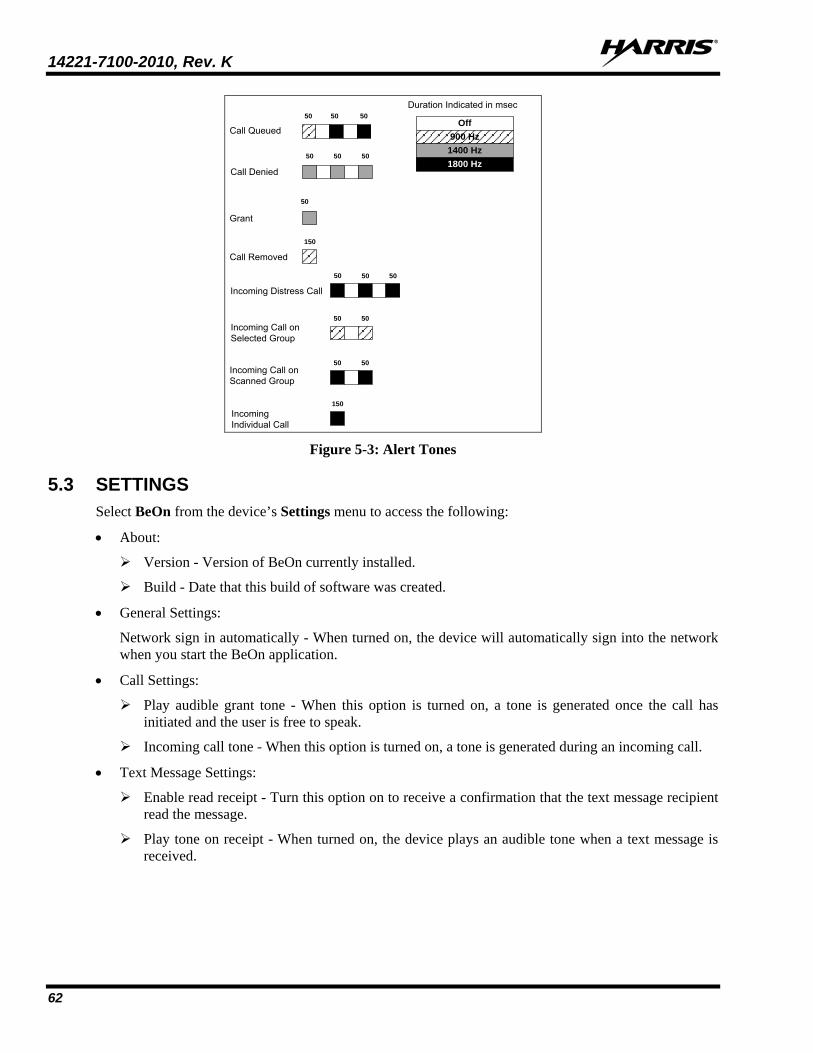
14221-7100-2010, Rev. K
62
Duration Indicated in msec
Incoming Individual Call
150
Incoming Call on Scanned Group
Incoming Distress Call
50 50 50
Incoming Call on Selected Group
50 50
Call Removed
150
Call Denied
50 50 50
Call Queued
50 50 50
Grant
50
50 50
Off900 Hz
1400 Hz1800 Hz
Figure 5-3: Alert Tones
5.3 SETTINGS Select BeOn from the device’s Settings menu to access the following:
• About:
Version - Version of BeOn currently installed.
Build - Date that this build of software was created.
• General Settings:
Network sign in automatically - When turned on, the device will automatically sign into the network when you start the BeOn application.
• Call Settings:
Play audible grant tone - When this option is turned on, a tone is generated once the call has initiated and the user is free to speak.
Incoming call tone - When this option is turned on, a tone is generated during an incoming call.
• Text Message Settings:
Enable read receipt - Turn this option on to receive a confirmation that the text message recipient read the message.
Play tone on receipt - When turned on, the device plays an audible tone when a text message is received.

14221-7100-2010, Rev. K
63
5.4 USER INTERFACE
5.4.1 Main Display Figure 5-4 and Figure 5-5 are examples of the iOS BeOn displays. The top of the display hosts the menu button, number of notifications (touch to display notifications), registration status, and presence button. A colorful icon indicates the application is registered with the system; a non-colorful icon indicates the application is not registered with the system. The bottom of the display hosts the Status Bar (see Section 5.4.2 for more information).
Figure 5-4: iPhone Home Screen
Figure 5-5: iPad Home Screen

14221-7100-2010, Rev. K
64
Tap in the top left corner of the display to access the BeOn menu:
• Home - Displays the Home screen. The Home screen is displayed when the BeOn application starts (see Section 5.4.4).
• Groups - Opens the Groups screen which displays the configured talk groups (see Section 5.4.6). • Contacts - Opens the Contacts screen which displays all contacts in the PTT address book (see
Section 5.4.6.2). • History - Opens the History screen which lists all incoming and outgoing calls, conversations, text
messages, distress initiations, and distress cancellations (see Section 5.4.8). • Profiles - Opens the Profiles tab which displays available profiles (see Section 5.4.9).
• Map (iPhone) - Displays the Map screen (see Section 5.4.5).
• Individual Call/Message (iPhone) - Allows you to send an individual text message or make a user the target for the next PTT operation.
• Sign Out - Deregisters the user from the network; no new calls are received.
• Lock - This option allows you to enable/disable PIN Lock.
• Preference - Opens the Preferences menu (see Section 5.4.10).
• Audio Option - Allows you to specify iPhone Speaker or iPhone.
Figure 5-6: Audio Option
• Legal + Info - Displays copyright and BeOn version information.

14221-7100-2010, Rev. K
65
5.4.2 Status Bar The bottom of the display, or Status Bar, acts as an on-screen PTT button by default. The Status Bar also displays the group or user currently selected for the next call when PTT is pressed, as well as the last call transmitted or received.
Figure 5-7: Status Bar - iPhone
Figure 5-8: Status Bar - iPad
The color of the Status Bar changes based on the current activity: • Blue background indicates “Idle” mode (i.e., no active call). • Yellow background indicates outgoing calls. • Green background indicates incoming calls • Red background indicates “distress” mode.
When idle, the left side of the Status bar is a tappable area that displays groups that are in distress. When distress calls are placed or received and the user is also in distress, the entire call status area has a red background.
5.4.3 Adjust Volume Use the device’s volume up and down buttons to increase/decrease volume.

14221-7100-2010, Rev. K
66
5.4.4 Home The Home screen is displayed when the BeOn application starts. The iPhone Home screen features a large PTT button and the distress button. The iPad Home screen hosts the map.
Figure 5-9: Home Screen - iPad
Figure 5-10: Home Screen - iPhone
5.4.5 Geographic Mapping BeOn utilizes Google Maps as part of its situational awareness capability. The map defaults to showing members of the currently selected group on the map. The map is centered on the location of your device; other members may not be visible on the map. Wherever possible, User IDs are displayed as descriptive alias names if the User ID has a contact entry. When a VPS (StatusAware) is available in the system, the BeOn client receives information about the type of equipment an individual is carrying (e.g., BeOn, LMR, etc.). This affects the displayed icon.
Four map options are available. Select the desired view from the Layer and Assets menu, accessed on the iPhone by tapping the right-hand tab (see Figure 5-11) or select the Layers menu option from the top of the iPad Home Screen.
• Streets - displays the default road map view.
• Hybrid - displays a mixture of normal and satellite views.
• Satellite - displays Google Earth satellite images.
• Physical - displays a physical map based on terrain information.

14221-7100-2010, Rev. K
67
Figure 5-11: Layer and Asset Menu - iPhone
Figure 5-12: Layers Menu - iPad

14221-7100-2010, Rev. K
68
5.4.5.1 Smart Location Update
The Smart Location Update feature allows the user to configure time and distance intervals to settings which could be detrimental to the devices battery life if values are used with very short elapsed time or distance between location updates. Each location update requires power from GPS, Wi-Fi, Cell, and other radios.
Maps are updated when notified by the platform that the location has changed. The Smart Location Update feature allows the user to specify the frequency of location updates sent to the network. The VNIC presence service provides location updates to subscribers in the same enterprise/agency. Smart Location Update parameters are configured via the Preferences menu (see Section 5.4.10).
The Time interval, Distance interval, Distance units, and Maximum update frequency parameters are selectable even if Smart Location Update is disabled. These parameters are used for normal location requests for local use. When Smart Location Update is disabled, location updates are only sent to the network in the following circumstances:
• Initiation of a Group Call, Individual Call, or Distress Call.
• With Text Messages.
• When sending SDS acknowledgements in response to location queries.
• With presence state changes.
5.4.5.2 Call Indications If the map is displayed during a call and the person making the call is visible on the map, the user’s icon has a blinking radio wave icon around it during the entirety of the call. The radio wave is blue during normal calls and red during distress calls.
Figure 5-13: Normal Call Indication
Figure 5-14: Distress Call Indication
5.4.5.3 Tracking Users and Groups The BeOn iOS application allows the tracking of up to 38 users OR a single group with up to 38 of its registered users. The users tracked can be a combination of users from the contact list or group members.
1. From the iPhone’s Layer and Assets menu (see Figure 5-11) or from the top of the iPads Home screen, select Map Group or Map Contacts.
2. Check the contacts or group that you want to map (up to 38 contacts OR a single group with up to 38 of its registered users can be mapped). If no group/contacts are selected, only self is mapped.
3. Tap Done to map the selected users/group.
CAUTION

14221-7100-2010, Rev. K
69
Figure 5-15: Map Contacts
Figure 5-16: Map Groups
Or
Select the Map Group/Map Contact option from the context menus on the Groups or Contacts screen (see Sections 5.4.6 and 5.4.7 for more information).
5.4.6 Groups
5.4.6.1 iPhone Select Groups from the menu to view the configured talk groups. Tap the icon next to the group name to select the group. Selecting a new group updates the Status bar for the next PTT.
Figure 5-17: Groups

14221-7100-2010, Rev. K
70
Tap the group name to open a context menu. The choices allow the BeOn user to view registered users in the talk group, send a text, map a group, or review the call history for a talk group.
• Members - Displays the individuals that make up the group. There is a row entry for each group member showing the presence icon, member name, supervisor status, and the VIDA ID. Tap a group member to open a context menu:
iCall - Causes that contact list entry to be selected for an individual call.
Map Contact - Maps the contact.
Get Presence - Retrieves the current presence state of the contact. The presence icon, displayed to the left of the first name, is updated according to the presence state.
Send Text - Allows you to send a text message to the selected contact.
History - Displays the call history of this contact.
Add Contact/Modify - Adds the group member to the Contacts list. If already in the contact list, allows you to modify.
• Send Text - Allows text messaging to groups. See Section 5.5.6.
• Map Group - Adds the group to the map.
• History - Displays the call history for that group.
Figure 5-18: Group
Context Menu
5.4.6.2 iPad Select Groups from the menu to view the configured talk groups. The column on the left displays groups; the column on the right displays group members. Tap the icon next to the group name to select the group. Selecting a new group updates the Status bar for the next PTT.
Figure 5-19: Groups

14221-7100-2010, Rev. K
71
Tap the group name or group member to open a context menu.
The group context menu allows the BeOn user to see registered users in the talk group, send a text, map a group, or review the call history for a talk group.
• Members - Displays the individuals that make up the group. There is a row entry for each group member showing the presence icon, member name, supervisor status, and the VIDA ID.
• Send Text - Allows text messaging to groups. See Section 5.5.6.
• Map Group - Adds the group to the map.
• History - Displays the call history for that group.
Options available from the Members context menu include:
• iCall - Causes that contact list entry to be selected for an individual call.
• Map Contact - Maps the contact.
• Get Presence - Retrieves the current presence state of the contact. The presence icon, displayed to the left of the first name, is updated according to the presence state.
• Send Text - Allows you to send a text message to the selected contact.
• History - Displays the call history of this member.
• Add Contact/Modify - Adds the group member to the Contacts list. If already in the contact list, allows you to modify.
Figure 5-20: Group Context
Menus

14221-7100-2010, Rev. K
72
5.4.7 Contacts The Contacts screen contains one entry for each of the contacts in the PTT address book. If the list is longer than the screen allows, a scroll bar appears. The first and last name, VIDA user ID, display name, and current presence (if applicable) of each contact is displayed. Refer to Table 2-3 for a description of the icons displayed for each contact.
Figure 5-21: Contacts - iPad
Figure 5-22: Contacts - iPhone
5.4.7.1 Add a New Contact
1. On the iPhone, tap + in the top right corner of the Contacts screen. On the iPad, tap in the left hand column of the Contacts screen and select Add Contact.
2. Enter the contact’s name and User Id (comprised of the Region, Agency, and User information).
3. Tap Done.

14221-7100-2010, Rev. K
73
5.4.7.2 Delete Contacts While on the Contacts screen:
• Tap a contact and tap Delete.
or
• On the iPhone, tap (-) in the top right corner, mark contacts you want to delete, and tap Delete, or tap Delete All to delete all contacts in the list.
or
• On the iPad, tap in the left hand column of the Contacts screen and select Delete Contact. Tap all contacts that you want to delete and tap Delete All.
5.4.7.3 Contacts Context Menu Tap anywhere on the contact row to open a context menu.
The user has the following options:
• iCall: Causes that contact list entry to be selected for an individual call. This has the same effect as a short tap on the contact entry on the main contacts list.
• Map Contact: Adds Contact to the map.
• Get Presence: Retrieves the current presence state of the contact. The presence icon, displayed to the left of the first name, is updated according to the presence state.
• Send Text: Sends a text message to the selected contact.
• History: Displays the call history of this contact.
• Modify: After selecting this option, the user can edit the currently selected contact information.
• Delete: Permanently deletes the selected contact after prompting the user to confirm the delete.
Figure 5-23: Contacts
Context Menu
Most of these options are also available in the right-hand column of the iPad Contacts screen.
5.4.8 History The History screen (Figure 5-24 and Figure 5-25) lists incoming and outgoing calls, conversations, text messages, location (GPS) requests, distress initiations, and distress cancellations. Up to 200 events can be stored in the history. After reaching 200, new events will overwrite existing events, starting with the oldest first. Tap an event to playback audio if available. On the iPad, the Call Details are displayed in the right-hand column of the History screen. On the iPhone, tap an event to display the Call Details screen.
To select messages for deletion on the History screen, tap Edit, tap the records you want to delete, and tap Delete. You can also tap Delete from the Call Details screen to delete the selected record.
NOTE

14221-7100-2010, Rev. K
74
Figure 5-24: History and Call Details - iPhone
Figure 5-25: History and Call Details - iPad
The information displayed in the Call Details window differs depending on the type of call. Call details can include the speaker, call recipient, call time, and location.
• Get Presence: Retrieves the current presence state of the contact. A notification is created to inform the user of the resulting presence, and that contact’s presence information in the Contacts tab is updated with this information.
• Next Call: Makes the selected entity the target for the next PTT operation.
• Send Text: Allows you to send a text message to the selected entity.
• Add Contact: Adds the selected user to the Contacts list.

14221-7100-2010, Rev. K
75
5.4.9 Profiles View available profiles from the Profiles screen. Every BeOn subscriber has a personality which can contain up to 16 profiles. Profiles allow the BeOn subscriber to quickly change the organization associations of the device for different roles, activities, or regional communications. Each profile can contain up to 16 groups. When a profile becomes the ‘active’ profile, the device scans all groups contained in that profile. A check mark indicates the ‘active’ profile. Only one profile is active at a time. Tap a profile to make it active.
Each profile is characterized by the following:
• Can contain 0 or 1 Scan Priority 1 (P1) group
• Can contain 0 or 1 Scan Priority 2 (P2) group
• Can contain 0 to 16 Scan Priority 3 (P3) groups
• Distress behavior (see Section 5.5.10)
• Supervisor flag for each group in the profile
A user can change the ‘selected’ group of an active profile by choosing a different group to be the Target or ‘Next Call.’ Selecting an individual contact as ‘next call’ does not have any effect on the active profile.
On the iPad, groups belonging to the profile are displayed in the right-hand column of the Profiles screen. On the iPhone, tap > next to a profile to view its groups. Tap > next to a group to view its users.
Figure 5-26 - Profiles - iPad
Figure 5-27: Profiles - iPhone

14221-7100-2010, Rev. K
76
5.4.10 Preferences Tap to open the menu. Tap Preferences.
Figure 5-28: Preferences - iPhone
Figure 5-29: Preferences - iPad
5.4.10.1 Network Settings Displays Network Settings.
5.4.10.2 Call Settings • Conversation Timeout - Group and individual calls are consolidated into conversation entries in the
History tab based this value. Calls made after this time expires are not grouped in the conversation.
• Talk Back Timer - When enabled, after receiving a call, the caller (Individual or Group) is temporarily assigned as the Next Call for 10 seconds (a timer counts down in the lower left of the

14221-7100-2010, Rev. K
77
screen). This allows the user to return the call within 10 seconds. The Talk Back timer will not show the countdown if the Next Call already displays the same value as the incoming call. Tap Talk Back Timer, tap Talk Back Timer Enabled to turn on, and enter the duration. Default is 1 second, and acceptable values are 1 to 30. When the “Turn on Talk Back timer” setting is off, this setting is disabled.
• Call Recording: If enabled by the system administrator, the Call Recording option allows the user to enable/disable call recording. Enabling Call Recording saves all calls to the device. If Call Recording is disabled when a call comes in, the call cannot be played back and is not available from the History tab.
• Display Distress Confirmation: When enabled, BeOn prompts the user to confirm a distress declaration.
5.4.10.3 Location Settings Tap to display the Location Settings window.
• Smart location enabled: When smart location is turned on, the BeOn subscriber device updates its location every x minutes (Time Interval) or y meters (Distance Interval), whichever happens first but no more that z seconds (Max Update Frequency).
Time interval - Specify the time interval at which the subscriber device will update its location. Range: 10 seconds to 1 hour in second intervals. Default: 5 minutes.
Distance interval - Specify the distance at which the subscriber device will update its location. Range (in meters/kilometers): 50 m, 100 m, 200 m, 400 m, 800 m, 1.6 km, 3.2 km, 6.4 km, 10 km. Range (in feet/miles): 125 ft, 250 ft, 500 ft, 0.25 mi, 0.5 mi, 1 mi, 2 mi, 4 mi, 6 mi.
Max update frequency - Range: 1 sec to 1 hour in second increments. Default: 30 seconds.
Distance Units - Specify the units (Metric or English) used for “Distance interval.”
• Location Accuracy - Specify the accuracy of the location information.
5.4.10.4 Security Settings (Encrypted Version of BeOn iOS Client Only)
• Zeroize - Removes all encryption keys.
• Reset Message Numbers - Resets message numbers to zero.
• Request Rekey - Requests a rekey from the KMF (OTAR).
• Secure Mode - Check to enable encryption; uncheck to disable encryption.
• Security key details - Displays OTAR Enabled status, KMF Status, provisioned Storage Location Number (SLN) bindings and key presence.
OTAR Enabled:
Yes = RSI from the UAS matches the RSI included in the ukek file.
No = RSIs do not match (could be an RSI=0 problem; do a force update).
KMF Status:
Configured = KMF IP address is present.
Not Configured = App does not have KMF IP address.
Registered = KMF has completed registration process with client.
14221-7100-2010, Rev. K
78
Unregistered = Client has not registered with the KMF.
• Load Encryption Keys - Select this option to manually load keys.
5.4.10.5 Playback Calibration: Tap PlayBack Calibration to open the PlayBack Calibration screen. From here, adjust the amount of gain added to the incoming audio. Tap Save to save changes, tap Default to return to default setting, or tap Reset to reset to last saved value.
5.5 USING THE SOFTWARE
5.5.1 Group Calls
5.5.1.1 Transmit to a Group 1. Tap a call record from the History screen and select Next Call, or select a group from the Groups
screen. The last selected Group appears in the Status bar.
2. Touch and hold the PTT button on the Home screen (iPhone only), or tap and hold the Status bar to transmit. When transmitting, the Status bar is yellow.
3. When finished, release PTT.
5.5.1.2 Incoming Group Calls During an incoming group call, the Status bar is green and displays the Caller ID. After the talk spurt ends, the call log is updated. The Status window is cleared after approximately two seconds.
If the talkback timer is enabled in the Preferences menu (Section 5.4.10) and a call is initiated on a group you are scanning, but is not your default group, the scanned group’s name is displayed as the next call with a timer counting down. Press the PTT button before the timer expires to respond to the group. When the timer expires, the Next Call displayed returns to the default group.
5.5.2 Individual Calls
5.5.2.1 Transmit to an Individual Pre-Stored or Received Individual Calls
1. Tap an event on the History screen and select Next Call, or tap a contact from the Contacts screen and select iCall from the context menu.
2. Tap the PTT button on the Home screen, or tap and hold the Status bar to initiate the call. When transmitting, the Status bar is yellow.
Direct Dial an Individual - iPhone
1. Tap to open the menu.
2. Tap Individual Call/Message.
3. Enter the User ID and WACN and tap Set as Next Target.
4. Press PTT to initiate the call. If the dialed number is in the Contact list, the alias is displayed. Call information is displayed in the Status Bar.

14221-7100-2010, Rev. K
79
Direct Dial an Individual - iPad
1. Tap iCall on the Home screen, next to the menu button.
2. Enter the User ID and WACN and tap Set as Next Target.
3. Press PTT to initiate the call. If the dialed number is in the Contact list, the alias is displayed. Call information is displayed in the Status Bar.
5.5.2.2 Incoming Individual Calls During an incoming individual call, the status bar is green and displays the Caller Alias, and/or VIDA, depending on what information is currently available.
Figure 5-30: Incoming Individual Call
5.5.3 Ignore a Call Tap to ignore an incoming group or individual call. Once a group is ignored, calls from that group are not received until the group call has ended and the call’s hang timer has expired. If the user places a PTT call on that group, even during the hang timer countdown, the call is placed and the group is no longer ignored. Calls cannot be ignored while the user is in a local distress.
5.5.4 Conversations Group and individual calls are consolidated into conversation entries in the History screen based on the Conversation Timeout value in Call Settings. If any call is either placed or received and its source (group or individual) matches the last call placed or received, the previous and current calls are placed into a conversation and the conversation entry is displayed in the History screen.

14221-7100-2010, Rev. K
80
5.5.5 Sending an Individual Text Message 1. Tap a contact on the Contacts Screen and select Send Text from the context menu or select Send
Text from the Call Details screen.
2. Enter a message, up to 214 characters, and tap Send.
Or
1. On the iPhone, tap to open the menu and tap Individual Call/Message. On the iPad, tap iCall next to the menu button.
2. Enter User ID and tap Send Text.
3. Enter a message, up to 214 characters, and tap Send.
5.5.6 Sending a Text Message to a Group 1. Tap a group on the Groups Screen and select Send Text or select Send Text from the Call Details
screen.
2. The message window opens. The top of the window displays Receipt and Recipient options (e.g., “No Receipt” and “Single Recipient”).
Depending on system configuration, the following Report Type options may be available when sending a group text:
• None - No receipt required.
• One recipient - The originator receives a receipt if at least one target device receives the message.
• Count recipients - The originating device receives a count of the acknowledgements received from the receiving devices until a timeout.
3. Enter a message, up to 214 characters.
4. Tap Send.
5.5.7 Receiving a Message 1. A number in the top of the display indicates unread BeOn notifications, such as text messages and
distresses (see Figure 5-4). Tap the icon and drag down.
2. Select the Text Message under Notifications.
5.5.8 Presence User and group presence services support the transmission of the status of users and groups to interested users.
Perform the following to set your presence options:
1. Tap the Presence icon (e.g., ).
2. Select the desired option:
• Available - The BeOn user is registered in the system.
• Silent - Indicates that the provider is not presently listening to PTT calls. The BeOn client records incoming calls during the Silent/Vibrate state, but plays neither received audio nor floor control tones.

14221-7100-2010, Rev. K
81
• Agency specific states can also be set up by the System Administrator (for example, “In Transit” or “Out to Lunch”).
In addition to presence options available to the user, two more states are utilized by the system, but are considered automatic states:
• Busy - In systems that support simultaneous voice and packet data services, “Busy” reflects whether or not the provider is in a circuit switched call and is thereby temporarily unavailable to listen to or respond to PTT communications. In the Busy state, the BeOn client creates call-log records for all talk-spurts that were not played and records received audio. See the following note.
• Unavailable - The BeOn user is not registered in the system. See the following note.
“Busy” and “Unavailable” cannot be set by the user; they are automatic states that kick in when the user is taking a circuit switch (normal phone) call and when they are not registered in the system, respectively.
Users can query the presence of other users to determine if they are available for BeOn group and individual calls.
5.5.9 Scanning When a profile becomes ‘active,’ the device is scanning all the groups contained in that profile. Only one profile is active at a time. Refer to Section 4.4.8 for more information on profiles.
5.5.9.1 Scanning Priority When scanning is enabled, a higher priority incoming call overrides the receive audio of a lower priority incoming call.
The following lists the scan priority order from highest to lowest:
1. Distress call
2. Individual call
3. Priority 1 (P1) call
4. Priority 2 (P2) call
5. Priority 3 (P3) call
5.5.9.2 Disable Scanning When the scanning feature is disabled, only the selected group is monitored by the BeOn application. Tap the Scanning icon ( ) on the Groups or Profiles screen to disable scanning. When disabled, the Scanning icon reflects a disabled scanning state ( ).
NOTE

14221-7100-2010, Rev. K
82
5.5.9.3 Enable Scanning When scanning is enabled, all groups in the currently active profile are monitored by the BeOn application. Tap the Scanning icon ( ) on the Groups or Profiles screen to enable scanning. When enabled, the Scanning icon reflects an enabled scanning state ( ).
5.5.10 Distress Distress behavior is defined by the currently active profile. The following distress behaviors are supported:
• None.
• Distress alert only. The user must clear the alert. There is no group state, only an individual state. The declaring user can clear the individual distress state. A console user can clear the individual state at the VNIC, but not the user’s local state.
• Distress alert and distress call on the default distress talk group. Tapping Cancel Distress clears both. The user must clear the alert locally. The declaring user or console can clear the individual distress state on the network. Only the declaring user can clear the local state. An authorized entity such as a console, supervisor, or network management system can clear the
group distress. Declaring users who are authorized to clear group distresses can clear both the individual and
group distress.
• Distress alert and distress call on the selected talk group. Tapping Cancel Distress clears both. The user must clear the alert locally. The declaring user or console can clear the individual distress state on the network. Only the declaring user can clear the local state. An authorized entity such as a console, supervisor, or network management system can clear the
group distress. Declaring users who are authorized to clear group distresses can clear both the individual and
group distress.
• Distress call on the default distress talk group. Tapping Cancel Distress clears the group distress. An authorized entity such as a console, supervisor, or network management system can clear the
group distress. Declaring users who are authorized to clear group distresses can clear the group distress.
• Distress call on the selected talk group. Tapping Cancel Distress clears the group distress. An authorized entity such as a console, supervisor, or network management system can clear the
group distress. Declaring users who are authorized to clear group distresses can clear the group distress.

14221-7100-2010, Rev. K
83
5.5.11 Initiate a Distress 1. On the iPhone, tap on the Home screen. On the iPad, tap in
the Status Bar.
2. If “Display Distress Confirmation” is enabled in Preferences Call Settings, tap Ok to confirm the distress at the prompt. The distress is initiated on the distress group which may be different than your currently selected group.
3. The display appears as shown below during a distress. If the auto-key feature is enabled, an automatic PTT occurs for a configurable length of time following the initiation of a distress on a group. Pressing PTT during this time interrupts the auto-key timer.
Depending on the distress behavior defined by the system administrator, you may not be able to change the next call, profile, or scanning until the distress is cleared.
5.5.12 Clear a Distress
Only a supervisor can clear a distress for a group. Non-supervisors can only clear a distress for themselves.
1. Tap the distress indication in the Status Bar of the display.
2. Tap Clear to clear either the distress for yourself and/or for the group in
distress (if you have supervisor privileges). If you are not the supervisor, you can only clear the distress for yourself.
NOTE
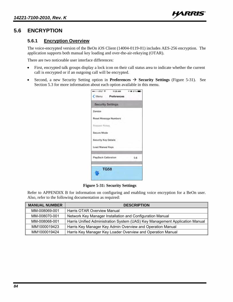
14221-7100-2010, Rev. K
84
5.6 ENCRYPTION
5.6.1 Encryption Overview The voice-encrypted version of the BeOn iOS Client (14004-0119-01) includes AES-256 encryption. The application supports both manual key loading and over-the-air-rekeying (OTAR).
There are two noticeable user interface differences:
• First, encrypted talk groups display a lock icon on their call status area to indicate whether the current call is encrypted or if an outgoing call will be encrypted.
• Second, a new Security Setting option in Preferences Security Settings (Figure 5-31). See Section 5.3 for more information about each option available in this menu.
Figure 5-31: Security Settings
Refer to APPENDIX B for information on configuring and enabling voice encryption for a BeOn user. Also, refer to the following documentation as required:
MANUAL NUMBER DESCRIPTION MM-008069-001 Harris OTAR Overview Manual MM-008070-001 Network Key Manager Installation and Configuration Manual MM-008068-001 Harris Unified Administration System (UAS) Key Management Application Manual MM1000019423 Harris Key Manager Key Admin Overview and Operation Manual MM1000019424 Harris Key Manager Key Loader Overview and Operation Manual
14221-7100-2010, Rev. K
85
5.6.2 Configuring System for Encryption The following are necessary for encrypted voice communication on BeOn devices:
• The key number in Harris Key Manager must match the Storage Location Number (SLN) binding number for the Crypto Net.
• The Key ID in Harris Key Manager must match the active key ID in the Unified Administration System (UAS).
• The BeOn user must be added to the Crypto Net.
• Groups must be added in Harris Key Manager (for that key ID) and the Crypto Net in the UAS.
5.6.2.1 Group and Crypto Net Administration
The “Delete Key” operation on an End User in the “Manage Crypto Nets” section of the UAS is not supported in BeOn at this time. The user must use the “Zeroize” function in Preferences of the BeOn client application to remove key material.
In the UAS, define a Crypto Net that contains the users and groups targeted for encrypted communications.
• Users and groups must be added to the Crypto Net in order to participate in encrypted communications.
• Make a note of Crypto Net SLN and Active Key IDs.
• The SLN binding number must match the key number entered in the Key Admin tool.
• The Active Key ID in the UAS must match the Key ID in the Key Admin tool.
Refer to the Harris UAS Key Management Application manual (MM-008068-001) for instructions on how to configure a Crypto Net.
5.6.2.2 Distributed Key File Generation (.dkf) The Harris Key Manager tool allows entry of key information and export of that key information into a distributed key file (.dkf) that can then be added to the BeOn application to support encrypted voice communications.
• Groups targeted for encrypted communications must be added in the Harris Key Manager to allow for encrypted communications.
• The key number entered in the Harris Key Admin tool must match the key SLN binding number entered in the UAS.
• The Key IDs entered in the Key Admin tool must match the SLN binding number chosen in the UAS.
• The Key Admin tool can then be used to generate a .dkf for later import on the BeOn phone.
Refer to the Harris Key Manager Key Admin Overview and Operation manual (MM1000019423) for more information on how to enter key information and export keys to a .dkf file.
5.6.3 Manual Key Loading Once the Distribution Key File and SLN Binding Report information from the Crypto Officer (CO) has been obtained, perform one of the following to load keys.
NOTE

14221-7100-2010, Rev. K
86
5.6.3.1 iTunes Perform the following to copy the key file to the iOS device via the iTunes desktop application:
1. Connect the iOS device to a computer with iTunes installed. Open iTunes, select the iOS device, and then select the Apps tab. Scroll down until you seen the File Sharing area:
2. Select the BeOn AES app. Drag and drop the ukek file into the top-level directory.
3. If the user is already logged into the BeOn application, the file is available to load manually via the
PreferencesSecurity SettingsLoad Manual Keys option.
Or
If the user is not logged into the BeOn application:
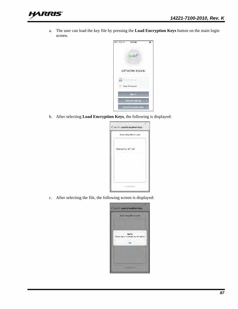
14221-7100-2010, Rev. K
87
a. The user can load the key file by pressing the Load Encryption Keys button on the main login screen.
b. After selecting Load Encryption Keys, the following is displayed:
c. After selecting the file, the following screen is displayed:

14221-7100-2010, Rev. K
88
d. Dismiss the popup and sign in as usual. If the key file is encrypted, upon attempting to sign in, the user is presented with a popup requiring the password for the key file, as shown:
5.6.3.2 Email Attachment Perform the following to load a key file attached to an email message:
1. Open the email containing the key file using the built-in mail application. BeOn must be running.
2. Select Open in BeOn PTT AES as shown in Figure 5-32.
Figure 5-32: Load Keys from Email

14221-7100-2010, Rev. K
89
3. If the user is not already logged into the BeOn application, the following is displayed:
4. Tap OK to dismiss the pop-up and sign in. If the key file is encrypted, a dialog is displayed
prompting the user for the password as shown below:

14221-7100-2010, Rev. K
90
5.6.3.3 Website Download You can load a key file from a Web site. The file is selected and the BeOn application is chosen to open it as shown in Figure 5-33. BeOn must be running.
Figure 5-33: Load Keys from Web Site
If the user is not already logged into the BeOn application, the following is displayed:

14221-7100-2010, Rev. K
91
Tap OK to dismiss the pop-up and sign in. If the key file is encrypted, a dialog is displayed prompting the user for the password as shown below:
It is the user’s responsibility to ensure that the key file is stored and transferred in a secure manner (e.g., via secure Web server or email service).
NOTE

14221-7100-2010, Rev. K
92
6. BEON WINDOWS CLIENT (BWC) The BeOn Windows Client (BWC) allows any administrator to listen to LMR traffic from a PC at a desk, or in a command and control vehicle, as well as talk to BeOn and P25 radio users in the field. The administrator can participate in PTT traffic and view the location and presence state of users on a map.
If an audio device is recognized by the operating system as a microphone and can be set as the default microphone in the system, it will work with the BWC. Examples include USB audio devices and external microphones attached to USB, PCI, or motherboard sound inputs. No specific set up is necessary.
Buttons on the PC’s keyboard can be configured as a PTT button via the PTT Shortcuts tab in the “Edit Settings” dialog. See Section 6.2.1.5 for more information.
6.1 START THE BWC 1. Launch the BWC from the Start menu All Programs BeOn BeOn Windows Client.
2. At the Login screen, enter your Username and Password. • Click the Network Settings button if you need to make modifications to your User ID, WACN,
Password, or LAS information (see Figure 3-4). Click Save after making changes. • Click the New user button if you need to create a new user (see Figure 3-3).
3. Click Login.
Figure 6-1: BWC Login
4. A dialog displays registration progress.
Figure 6-2: Registration Progress

14221-7100-2010, Rev. K
93
6.2 USER INTERFACE Figure 6-3 is an example of the BWC display. The BWC features a tabbed interface that allows users to quickly access key features. Click on a tab to pop the tab out, making it a moveable, resizable window. Click to return the tab to the main window.
The BWC supports tool tips, which are displayed when the mouse is hovered above a control.
Figure 6-3: Sample Main Display
• The Status Bar, at the bottom of the display, provides information about the last PTT, distress status, Text status, and Registration status. You can also edit settings and Presence Information from here. See Section 6.2.1 for more information.
• The Calls tab allows the user to transmit and receive individual calls and group calls, send group and individual texts, and add groups/individuals to the map. The Calls tab also allows you to change the selected profile and view groups assigned to that profile. See Section 6.2.2 for more information about the Calls tab.
• The Map tab initially shows the current user on the map. See Section 6.2.3 for more information on the Map tab.
• The Groups tab lists all members of the selected group. See Section 6.2.4 for more information on the Groups tab.
• The Contacts tab lists all of your contacts and allows you to add new contacts. See Section 6.2.5 for more information about the Contacts tab.
NOTE

14221-7100-2010, Rev. K
94
• The History tab lists received and transmitted calls, conversations, text messages, and distress calls. It also allows you to playback audio from the call if available. See Section 6.2.6 for more information about the History tab.
• The Text tab allows you to send text messages. See Section 6.2.7 for more information about the Text tab.
6.2.1 Status Bar The Status Bar is located at the bottom of the display. From the Status Bar, you can:
• View the caller and callee of the last PTT.
• Access Distress Status and Text Status dialogs.
• View Registration status.
• Access the Edit Settings dialog.
• Edit Presence Information.
The following sections describe the different elements of the Status Bar.
Figure 6-4: Status Bar
6.2.1.1 Distress Status
Click in the Status Bar to display the distress Status dialog. If there is one or more active distress, a number is displayed on the icon (e.g., ) indicating the number of entities in distress. The Distress Status dialog displays all entities in distress. Click Cancel Distress to clear the distress for yourself and/or for the group in distress (if you have supervisor privileges). If you are not a supervisor, you can only clear the distress for yourself. See Section 6.3.10 for more information on distress behavior.
Figure 6-5: Distress Status

14221-7100-2010, Rev. K
95
6.2.1.2 Text Status
Click in the Status Bar to open the Text Status dialog. The Text Status dialog allows you to see incoming text messages from other clients.
Figure 6-6: Text Status
6.2.1.3 Presence Icon
Click the presence icon (e.g., ) in the Status Bar to update your presence information. See Section 6.3.8 for more information on the Presence feature.
6.2.1.4 Registration Status The BeOn applications registration status is indicated by an icon in the Status Bar.
Indicates the BeOn application is registered with the system.
Indicates the BeOn application is not registered with the system.

14221-7100-2010, Rev. K
96
6.2.1.5 Edit Settings
Click the button in the Status Bar to access the Edit Settings dialog. The Edit Settings dialog consists of five tabs: Call, Text Message, Map, Network Settings, and About. After making changes, click Save.
Figure 6-7: Edit Settings
Call
• Play audible grant tone - When the user presses PTT, an audible sound is generated once the call has initiated and the user is free to speak.
• Turn on talkback timer - When checked, after receiving a call, the Individual caller is temporarily assigned as the Next Call for 10 seconds (a timer counts down next to the Individual in the Call Status Area of the ICall Tab). This allows the user to return the call within 10 seconds. The talkback timer will not show the countdown if the Next Call already displays the same value as the incoming call.
• Set talkback timer - Duration in seconds of the talkback timer (see previous setting). Default is 10 seconds, and acceptable values are 1 to 60. When the “Turn on Talk Back timer” setting is unchecked, this setting is disabled.
• Conversation timeout - Group and individual calls are consolidated into conversation entries in the History tab based this value. Calls made after this time expires are not grouped in the conversation.
• Display distress confirmation - When checked, the BWC will display distress confirmations.
• Maximum events to store - Specify the maximum number of events to store. Default is 1000.
• Allow call recording - If enabled by the system administrator, the Allow call recording option allows the user to enable/disable call recording. Enabling call recording saves all calls to the PC. If call recording is disabled when a call comes in, the call cannot be played back and is not available from the History tab.
• Show PTT notifications - If the Show PTT notification feature is enabled, a popup window displaying recent PTTs appears on top of all other application windows. The popup remains until the operator has acknowledged all notifications. See Section 6.3.3 for more information on PTT notifications. Show while window active - When checked, the PTT notification popup appears no matter the
state of the BWC application window. When unchecked, restoring the BWC application window while the PTT Notification popup is displayed hides the popup.

14221-7100-2010, Rev. K
97
Click selects next ICall - When checked, the source of the PTT notification just clicked is made the next ICall target. This lets the operator talk back to the source of a PTT without having to first find them in a list.
Text
• Enable read receipt - Check this option to receive a confirmation that the text message recipient read the message. This setting applies only to text messages sent to Individuals.
• Play tone on receipt - When checked, the device plays an audible tone when a text message is received.
Map
• Latitude/Longitude - Specify the latitude and longitude for your location.
• Hide My Location - When this option is checked, your icon no longer appears on the map and your name is displayed in italics on the Map indicating your location is being published as “unknown.”
• Enable smart location - When smart location is enabled, the BeOn client updates its location every x minutes (Time Interval) or y meters (Distance Interval), whichever happens first but no more than z seconds (Max Update Frequency). While this option is intended for mobile devices, it may be useful for a Windows Client user to keep their location “fresh” on theirs as well as other users’ maps.
• Location Timeout (sec) - Specify the time which should elapse before BeOn considers the location of users on the map to be too old or stale. Range: 30 to 9,999 seconds. Default: 300 seconds.
• Proxy Host/Proxy Port - Because the BeOn Windows Client must be Internet connected to use the Google Maps feature, a proxy configuration has been added to allow customers who deploy the client behind a firewall to operate.
Network
The Network Settings tab of the Edit Settings dialog allows you to modify your User ID, WACN, Password, LAS IP address, and LAS port.
Security
The Security tab is only present in the voice encrypted version of the BWC. See Section 6.4 for more information on encryption.
• Zeroize - Removes all encryption keys.
• Reset message numbers - Reset message numbers to zero for this UE.
• Request rekey - Requests a rekey from the KMF (OTAR).
• Secure mode - When checked, outgoing individual calls are encrypted.
• Security key details - Displays OTAR Enabled status, KMF Status, provisioned Storage Location Number (SLN) bindings and key presence.
OTAR Enabled:
Yes = RSI from the UAS matches the RSI included in the ukek file.
No = RSIs do not match (could be an RSI=0 problem; do a force update).
KMF Status:
Configured = KMF IP address is present.
Not Configured = App does not have KMF IP address.

14221-7100-2010, Rev. K
98
Registered = KMF has completed registration process with client.
Unregistered = Client has not registered with the KMF.
• Load Keys - Opens a dialog allowing the user to select and load key files.
PTT Shortcuts
The PTT Shortcuts tab allows you to configure a button on the keyboard as a PTT button for that entity.
Tone
The Tone tab allows the user to enable/disable tones and to choose what the application tones sound like by selecting another audio file to play instead of the default tones. The allowed audio file formats include .pcm or .wav, 8 kHz sample rate with 16-bit signed little-endian samples.
About
The About tab of the Edit Settings dialog displays copyright information, the software version, the enabled features, and the End User License Agreement.
6.2.2 Calls Tab Figure 6-8 is an example of the BWC Calls tab. From the Calls tab, the user can:
• Transmit and receive individual calls and group calls.
• Send individual and group texts.
• Add groups/individuals to the map.
• Change the selected profile and view groups assigned to that profile.
• Initiate a distress (see Section 6.3.10).
• Start/Stop scanning (see Section 6.3.9).
• Ignore a call (see Section 6.3.2.2).
• Adjust volume and mute audio.
Sections 6.2.2.1 through 6.2.2.3 describe the panels of the Calls tab.
The Call Status Areas in the ICall Panel, Group Panel, and Profile Panel act as PTT buttons for the contact or group associated with it. The icon on the left gives details about the group or call state. While idle, the icon on the group Call Status Area indicates scan priority and supervisor status, or indicates if the group is the current distress group. When transmitting or receiving, the icon shows an individual or group conversation icon, indicating a call is in progress. Refer to Table 2-3 for a description of all icons.
There are two text lines on the Call Status Areas. The top line displays the next call; i.e., who the target of the call is when PTT is pressed. The bottom line shows the current source of the call, or the source of the last call, if available.
The color of the Call Status area indicates the current activity:
• Blue background indicates “Idle” mode (i.e., no active call).
• Yellow background indicates outgoing calls.
• Green background indicates incoming calls.
• Red background indicates “distress” mode.
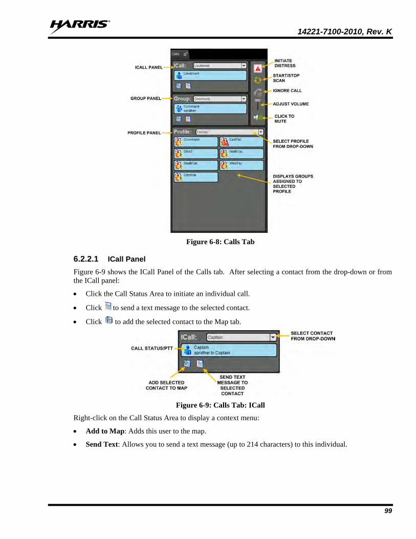
14221-7100-2010, Rev. K
99
Figure 6-8: Calls Tab
6.2.2.1 ICall Panel Figure 6-9 shows the ICall Panel of the Calls tab. After selecting a contact from the drop-down or from the ICall panel:
• Click the Call Status Area to initiate an individual call.
• Click to send a text message to the selected contact.
• Click to add the selected contact to the Map tab.
Figure 6-9: Calls Tab: ICall
Right-click on the Call Status Area to display a context menu:
• Add to Map: Adds this user to the map.
• Send Text: Allows you to send a text message (up to 214 characters) to this individual.

14221-7100-2010, Rev. K
100
6.2.2.2 Group Panel Figure 6-10 shows the Group Panel of the Calls tab. After selecting a group from the drop-down:
• Click the Call Status area to initiate a group call the selected group.
• Click to send a text to that group.
• Click to add the selected group to the Map tab.
Figure 6-10: Calls Tab: Groups
Right-click on the Call Status Area to display a context menu:
• Select Group: Makes this group the next call in the Group Panel.
• Add to Map: Adds this group to the map.
• Send Group Text: Allows you to send a text message (up to 214 characters) to this group.
• Mute: Mutes audio from this group. Right-click and select Unmute to unmute audio from this group.
6.2.2.3 Profile Panel Every BeOn subscriber has a personality which can contain up to 16 profiles. Profiles allow the BeOn subscriber to quickly change the organization associations of the device for different roles, activities, or regional communications. Each profile can contain up to 16 groups. When a profile becomes the ‘active’ profile, the device scans all groups contained in that profile. Only one profile is active at a time.
The Profile Panel allows you to change the selected profile and view groups assigned to the selected profile. You can transmit to any group in the profile by pressing and holding its Call Status Area. Right-click on a group’s status area to display a context menu:
• Select Group: Makes this group the next call in the Group Panel.
• Add to Map: Adds this group to the map.
• Send Group Text: Allows you to send a text message (up to 214 characters) to this group.
• Mute: Mutes audio from this group. Right-click and select Unmute to unmute audio from this group.

14221-7100-2010, Rev. K
101
Figure 6-11: Calls Tab: Profile
Each profile is characterized by the following:
• Can contain 0 or 1 Scan Priority 1 (P1) group
• Can contain 0 or 1 Scan Priority 2 (P2) group
• Can contain 0 to 16 Scan Priority 3 (P3) groups
• Distress behavior (see Section 6.3.10)
• Supervisor flag for each group in the profile (refer to Table 2-3).
6.2.3 Map Tab The BWC mapping interface uses Google Maps. As such, the BWC must be run on an Internet-connected machine. The user can map individuals, groups, and “pins.”
The individual icons on the map show the current presence state, if known. The icon is blue when the last received location is within the timeout period configured in the Settings dialog (see Section 6.2.1.5). If the location is not received within this time, the icon changes to gray. This feature instantly shows which individuals are active.
When a VPS (StatusAware) is available in the system, the BWC receives information about the type of equipment an individual is carrying (e.g., BeOn, LMR, etc.). This affects the displayed icon.
Right-click anywhere on the map (not occupied by a BeOn icon) to bring up a context menu. This context menu provides the ability to center the map, set your location, or add a pin.

14221-7100-2010, Rev. K
102
Figure 6-12: Map Tab Context Menu
6.2.3.1 Map Self
The current BWC user is always shown on the map. Right-click on the user’s icon on the map to bring up a context menu. This context menu provides the ability to center the map on the user or get more details about the user.
Figure 6-13: Current User Context Menu
The Details dialog includes the user’s name, alias, location, and time the location was received.
Figure 6-14: Mapped User Details Dialog
6.2.3.2 Map User
Individuals can be added to the map in various ways; for example, from the Calls Panel or the Groups, Contacts, or History Tabs, among others. Right-click on an individual’s icon on the map to bring up a context menu. This context menu provides the ability to center the map on the individual, set the individual as the next ICall, send a text to the individual, add the individual as a contact, or get more details about the individual.

14221-7100-2010, Rev. K
103
Figure 6-15: Mapped User Context Menu
The information provided in the Details dialog for the individual are the same as for the logged in user.
6.2.3.3 Map Pin
Pins can be added to the map as placeholders for events or objects. The user can add a pin by right-clicking anywhere on the map (not occupied by a BeOn icon) to bring up the context menu and selecting Add Pin. The New Pin dialog allows the user to choose a new and pick an icon for the pin.
Figure 6-16: New Pin
Right-click on a pin to bring up a context menu. This context menu provides the ability to center the map on the pin or modify the pin.
Figure 6-17: Pin Context Menu
6.2.3.4 Mapped Items
All of the items (individuals, groups, and pins) that have been added to the map are displayed in the Mapped Items Panel to the right of the map. This is a tabbed panel that allows instant access to all items, or just groups, users, or pins. The items are displayed in a tree to allow groups of users to be expanded or collapsed.
Figure 6-18: Mapped Items

14221-7100-2010, Rev. K
104
Due to system limitations, groups display the number of individual members in the group in the format “x of y.” The “x” indicates the number of members of the group received from the network, and the “y” indicates the total number of members in the group.
Right-click on any mapped item to bring up a context menu. This context menu provides the ability to center the map on the item, delete the item from the map, hide/unhide the item (make it visible or not on the map), or highlight/unhighlight the item (turns the icon green on the map so it stands out).
Figure 6-19: Mapped Items Context Menu
6.2.3.5 Call Indications If the Map tab is displayed during a call and the person making the call is visible on the map, the user’s icon has a blinking radio wave icon around it during the entirety of the call. The radio wave is blue during normal calls and red during distress calls.
Figure 6-20: Normal Call Indication
Figure 6-21: Distress Call Indication
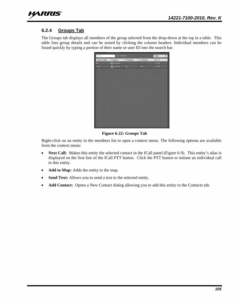
14221-7100-2010, Rev. K
105
6.2.4 Groups Tab The Groups tab displays all members of the group selected from the drop-down at the top in a table. This table lists group details and can be sorted by clicking the column headers. Individual members can be found quickly by typing a portion of their name or user ID into the search bar.
Figure 6-22: Groups Tab
Right-click on an entity in the members list to open a context menu. The following options are available from the context menu:
• Next Call: Makes this entity the selected contact in the ICall panel (Figure 6-9). This entity’s alias is displayed on the first line of the ICall PTT button. Click the PTT button to initiate an individual call to this entity.
• Add to Map: Adds the entity to the map.
• Send Text: Allows you to send a text to the selected entity.
• Add Contact: Opens a New Contact dialog allowing you to add this entity to the Contacts tab.

14221-7100-2010, Rev. K
106
6.2.5 Contacts Tab The Contacts tab contains an entry for each of the contacts in the PTT address book in a table. The table lists contact details, is searchable, and can be sorted by clicking the column header.
Figure 6-23: Contacts Tab
Right-click on an entry in the list to open a context menu. The following options are available from the context menu:
• Next Call: Makes this entity the selected contact in the ICall panel (Figure 6-9). This entity’s alias is displayed on the first line of the ICall PTT button. Click the PTT button to initiate an individual call to this entity.
• Add to Map: Adds the contact to the map.
• Send Text: Allows you to send a text to the selected contact.
• Get Presence: Retrieves the current presence state of the contact. If available, the presence state is displayed in the Presence column of the Contacts tab.
• Modify Contact: Allows you to edit the Alias or User ID of the selected contact.
• Delete Contact: Permanently deletes the selected contact.
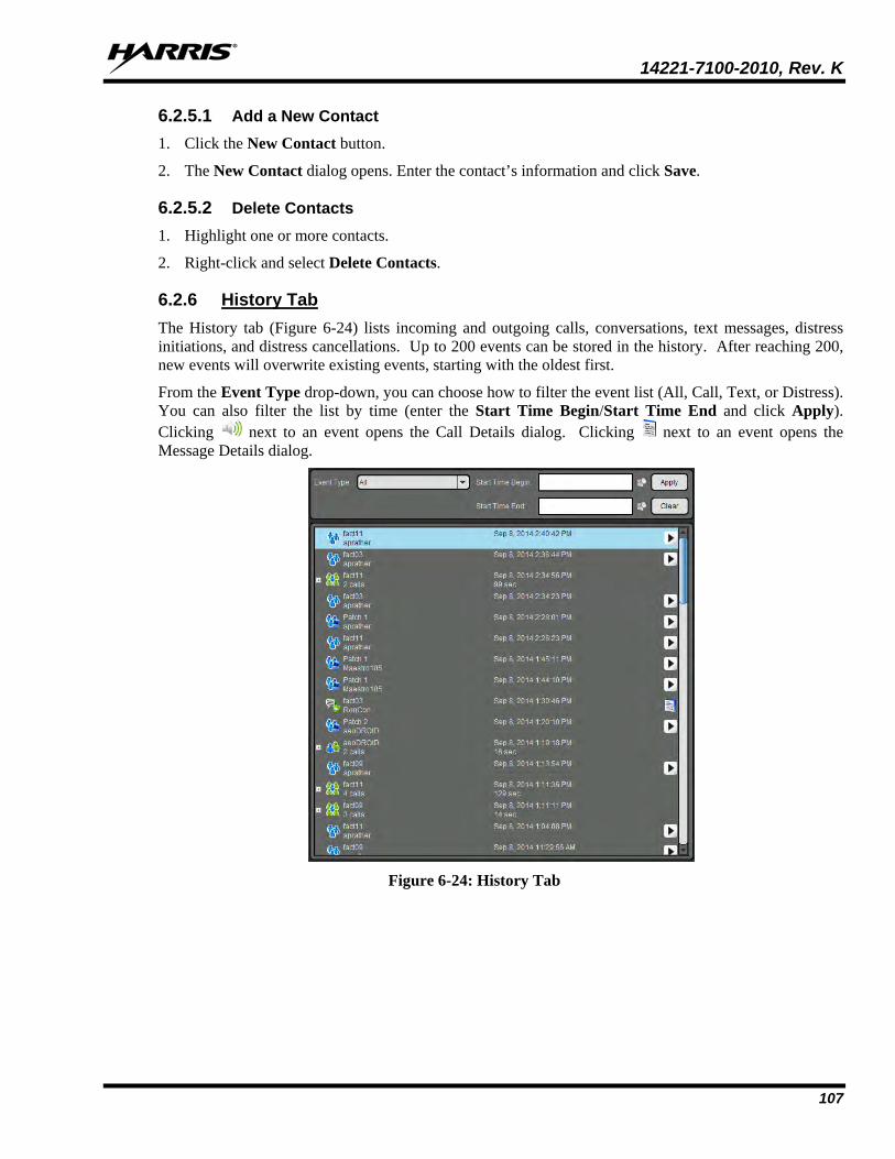
14221-7100-2010, Rev. K
107
6.2.5.1 Add a New Contact 1. Click the New Contact button.
2. The New Contact dialog opens. Enter the contact’s information and click Save.
6.2.5.2 Delete Contacts 1. Highlight one or more contacts.
2. Right-click and select Delete Contacts.
6.2.6 History Tab The History tab (Figure 6-24) lists incoming and outgoing calls, conversations, text messages, distress initiations, and distress cancellations. Up to 200 events can be stored in the history. After reaching 200, new events will overwrite existing events, starting with the oldest first.
From the Event Type drop-down, you can choose how to filter the event list (All, Call, Text, or Distress). You can also filter the list by time (enter the Start Time Begin/Start Time End and click Apply). Clicking next to an event opens the Call Details dialog. Clicking next to an event opens the Message Details dialog.
Figure 6-24: History Tab

14221-7100-2010, Rev. K
108
Right-click on an event to display a context menu.
• Details: Opens the Call Details dialog. The information displayed in this dialog differs depending on the type of call. Call details can include the speaker, call recipient, call time, and location. Click the
button to playback the selected call.
Figure 6-25: Call Details
• Delete Selected Event: Deletes the selected event.
• Next Call: Causes that individual to be selected for an individual call.
• Add User/Group to Map: Adds the highlighted user or group to the map.
• Send Text/Send Group Text: Allows you to send a text to the highlighted user or group.
• Add Contact: Adds this entity to your contact list.
6.2.7 Text Tab The Text Tab allows you to send and receive text messages. See Sections 6.3.6 and 6.3.7 for more information on Text Messaging.
Figure 6-26: BWC Text Tab
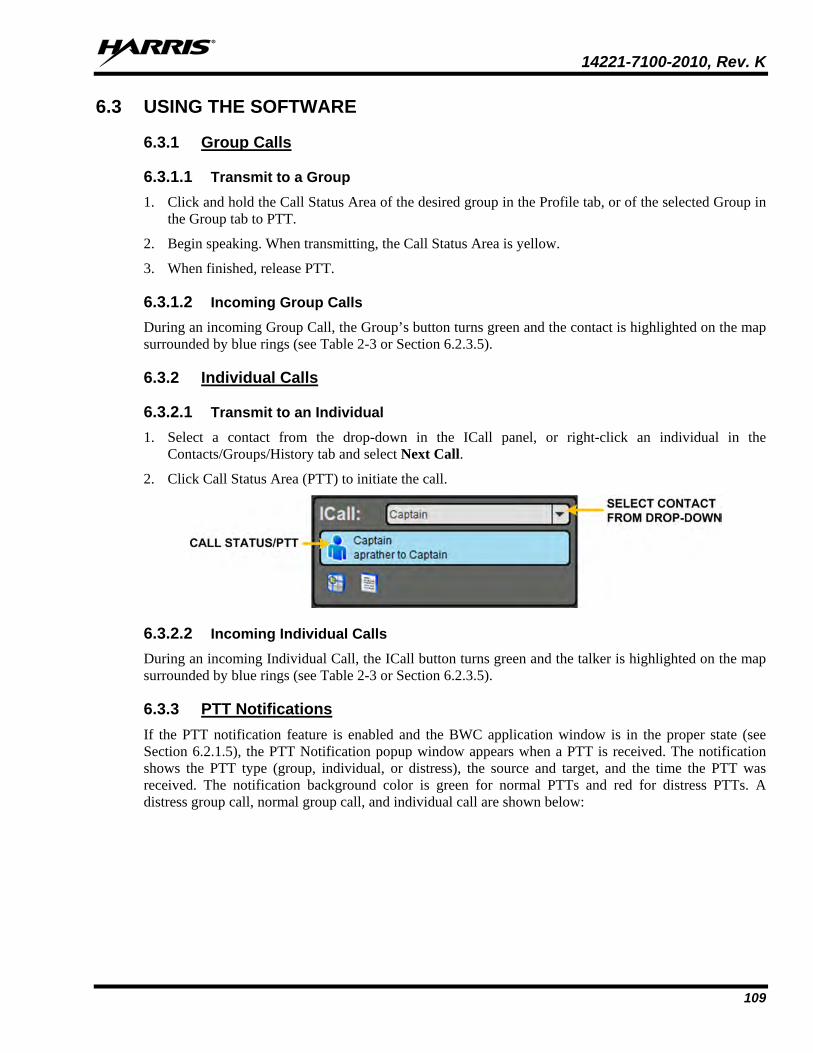
14221-7100-2010, Rev. K
109
6.3 USING THE SOFTWARE
6.3.1 Group Calls
6.3.1.1 Transmit to a Group 1. Click and hold the Call Status Area of the desired group in the Profile tab, or of the selected Group in
the Group tab to PTT.
2. Begin speaking. When transmitting, the Call Status Area is yellow.
3. When finished, release PTT.
6.3.1.2 Incoming Group Calls During an incoming Group Call, the Group’s button turns green and the contact is highlighted on the map surrounded by blue rings (see Table 2-3 or Section 6.2.3.5).
6.3.2 Individual Calls
6.3.2.1 Transmit to an Individual 1. Select a contact from the drop-down in the ICall panel, or right-click an individual in the
Contacts/Groups/History tab and select Next Call.
2. Click Call Status Area (PTT) to initiate the call.
6.3.2.2 Incoming Individual Calls During an incoming Individual Call, the ICall button turns green and the talker is highlighted on the map surrounded by blue rings (see Table 2-3 or Section 6.2.3.5).
6.3.3 PTT Notifications If the PTT notification feature is enabled and the BWC application window is in the proper state (see Section 6.2.1.5), the PTT Notification popup window appears when a PTT is received. The notification shows the PTT type (group, individual, or distress), the source and target, and the time the PTT was received. The notification background color is green for normal PTTs and red for distress PTTs. A distress group call, normal group call, and individual call are shown below:

14221-7100-2010, Rev. K
110
If a PTT is received with the same source and target as an existing notification, a badge is added to the notification indicating the number of PTTs received as shown below:
The background color reflects the state (green for normal or red for distress) of the last PTT made between a specific source and target. If a normal PTT follows a distress PTT, the background color reverts to green, but the badge indicating the number of PTTs remains red as show below:

14221-7100-2010, Rev. K
111
PTT notifications are added to the popup in the order they arrive (oldest at top). Subsequent PTTs with the same source and target do not affect the ordering.
The popup will not disappear until the operator acknowledges every notification. There are two ways to acknowledge notifications:
• Click the notification itself. This removes the notification from the PTT Notification popup, hides the popup, and brings the BWC application to the foreground. This lets the operator easily respond to the PTT. The popup reappears if another PTT is received or if the BWC application window is minimized.
• Click the ‘X’ on the notification. This removes the notification from the PTT Notification popup, but does not hide the popup or activate the BWC application window. This lets the operator easily dismiss a PTT notification without having to take further action.
In either case, if no more notifications are in the PTT Notification popup, the popup is closed. It is not possible to close the PTT Notification popup without clicking each notification or its ‘X.’
6.3.4 Conversations Group and individual calls are consolidated into conversation entries in the History tab based on the Conversation Timeout value configured in Call Settings (Section 6.2.1.5). If any call is either placed or received and its source matches the last call placed or received, the previous and current calls are placed into a conversation and the conversation entry is displayed in the History tab (see Section 6.2.6).
Figure 6-27: Conversations
6.3.5 Ignore a Call Incoming group and individual calls can be ignored by clicking . Once a group is ignored, calls from that group are not received until the group call has ended and the call’s hang timer has expired. If the user places a PTT call on that group/individual, even during the hang timer countdown, the call is placed and the group/individual is no longer ignored. Calls cannot be ignored while the user is in a distress.
6.3.6 Sending a Text Message
6.3.6.1 From Text Tab 1. Select a group or individual from the drop-down on the Text tab.
2. Click New Conversation.
3. Select “No receipt requested” or “Single Recipient” from the drop-down.
4. Enter a message in the Message box (up to 214 characters) and click Send.
6.3.6.2 From Groups, Contacts, Profile, and History Tabs 1. Right-click on a group or individual from the list. Select Send Group Text or Send Text.
Or Click in the ICall or Group dialog.

14221-7100-2010, Rev. K
112
2. Enter a message up to 214 characters and click Send.
6.3.7 Receiving a Message All received messages appear on the Text tab. A beep sounds when a new message is received and a badge is displayed with the count of unread messages on the Text Status icon in the status bar.
6.3.8 Presence User and group presence services support the transmission of the status of users and groups to interested users. The BWC supports real-time presence on the Groups tab and Map tab.
Perform the following to set your presence options:
1. Click the Presence icon in the Status bar.
2. Select the desired option:
• Available - The BeOn user is registered in the system.
• Silent - Indicates that the provider is not presently listening to PTT calls. The BeOn client records incoming calls during the Silent/Vibrate state, but plays neither received audio nor floor control tones.
• Agency specific states can also be set up by the System Administrator (for example, “In Transit” or “Out to Lunch”).
In addition to presence options available to the user, two more states are utilized by the system, but are considered automatic states:
• Busy - In the Busy state, the BeOn client creates call-log records for all talk-spurts that were not played and records received audio. See the following note.
• Unavailable - The BeOn user is not registered in the system. See the following note.
“Busy” and “Unavailable” cannot be set by the user; they are automatic states.
Users can query the presence of other users to determine if they are available for BeOn group and individual calls.
6.3.9 Scanning When a profile becomes ‘active,’ the device is scanning all the groups contained in that profile. Only one profile is active at a time. Refer to Section 4.4.8 for more information on profiles.
6.3.9.1 Scanning Priority When scanning is enabled, a higher priority incoming call overrides the receive audio of a lower priority incoming call.
The following lists the scan priority order from highest to lowest:
1. Distress call
2. Individual call
3. Priority 1 (P1) call
NOTE

14221-7100-2010, Rev. K
113
4. Priority 2 (P2) call
5. Priority 3 (P3) call
6.3.9.2 Disable Scanning When the scanning feature is disabled, only the selected group is monitored by the BeOn application.
To disable scanning, click the Scanning icon ( ) in the Calls tab. When disabled, the Scanning icon will reflect a disabled scanning state ( ).
6.3.9.3 Enable Scanning When scanning is enabled, all groups in the currently active profile is monitored by the BeOn application.
To enable scanning, click the Scanning icon ( ) in the Calls tab. When enabled, the Scanning icon will reflect an enabled scanning state ( ).
6.3.10 Distress Distress behavior is defined by the currently active profile. The following distress behaviors are supported:
• None.
• Distress alert only.
There is no group state, only an individual state.
The declaring user can clear the distress alert at the VNIC.
A console user can clear the distress alert at the VNIC.
• Distress alert and distress call are declared on the default distress talk group.
The declaring user clears the individual distress state on the network and the group distress state on the network.
An authorized entity such as a console, supervisor, or network management system can clear the group distress. In doing so, all individual distress states on the network are also cleared. Local states are cleared as well.
• Distress alert and distress call on the selected talk group.
The declaring user clears the individual distress state on the network and the group distress state on the network.
An authorized entity such as a console, supervisor, or network management system can clear the group distress. In doing so, the individual distress states on the network are also cleared. Local states are cleared as well.
• Distress alert and distress call on the default distress talk group. The user must clear the alert locally.
The declaring user or console can clear the individual distress state on the network.
Only the declaring user can clear the local state.
An authorized entity such as a console, supervisor, or network management system can clear the group distress.

14221-7100-2010, Rev. K
114
Declaring users who are authorized to clear group distresses can clear both the individual and group distress.
• Distress alert and distress call on the selected talk group. The user must clear the alert locally.
The declaring user or console can clear the individual distress state on the network.
Only the declaring user can clear the local state.
An authorized entity such as a console, supervisor, or network management system can clear the group distress.
Declaring users who are authorized to clear group distresses can clear both the individual and group distress.
• Distress alert only. The user must clear the alert.
There is no group state, only an individual state.
The declaring user can clear the individual distress state.
A console user can clear the individual state at the VNIC, but not the user’s local state.
6.3.11 Initiating a Distress 1. Press in the Calls tab.
2. Confirm the distress at the prompt. The distress is initiated on the distress group which may be different than your currently selected group.
3. The Calls tab and the PTT button of the group are red.
Figure 6-28: Calls Tab during Distress
Depending on the distress behavior defined by the system administrator, you may not be able to change the next call, profile, or scanning until the distress is cleared.

14221-7100-2010, Rev. K
115
6.3.12 Clearing a Distress
Only a supervisor can clear a distress for a group. Non-supervisors can only clear a distress for themselves.
1. Click the Distress Status icon in the Status Bar of the display.
2. Click Cancel Distress to clear either the distress for yourself and/or for the group in distress (if you have supervisor privileges). If you are not the supervisor, you can only clear the distress for yourself.
6.4 ENCRYPTION
6.4.1 Encryption Overview The BWC supports P25 encrypted communication using 256-bit Advanced Encryption Standard (AES). Encryption keys are loaded manually or by using Over-the-Air-Rekeying (OTAR) methods. Data Encryption Standard (DES) is not supported in BeOn at this time.
Encryption options are available on the Security tab of the Edit Settings dialog. See Section 6.2.1.5. Encrypted talkgroups display a icon on their call status area to indicate whether the current call is encrypted or if an outgoing call will be encrypted.
Refer to APPENDIX B for information on configuring and enabling voice encryption for a BeOn user. Also, refer to the following documentation as required:
MANUAL NUMBER DESCRIPTION MM-008069-001 Harris OTAR Overview Manual MM-008070-001 Network Key Manager Installation and Configuration Manual MM-008068-001 Harris Unified Administration System (UAS) Key Management Application Manual MM1000019423 Harris Key Manager Key Admin Overview and Operation Manual MM1000019424 Harris Key Manager Key Loader Overview and Operation Manual
6.4.2 Configuring System for Encryption The following are necessary for encrypted voice communication on BeOn devices:
• The key number in Harris Key Manager must match the Storage Location Number (SLN) binding number for the Crypto Net.
• The Key ID in Harris Key Manager must match the active key ID in the Unified Administration System (UAS).
• The BeOn user must be added to the Crypto Net.
• Groups must be added in Harris Key Manager (for that key ID) and the Crypto Net in the UAS.
NOTE

14221-7100-2010, Rev. K
116
6.4.2.1 Group and Crypto Net Administration
The “Delete Key” operation on an End User in the “Manage Crypto Nets” section of the UAS is not supported in BeOn at this time. The user must use the “Zeroize” function in Preferences of the BeOn client application to remove key material.
In the UAS, define a Crypto Net that contains the users and groups targeted for encrypted communications.
• Users and groups must be added to the Crypto Net in order to participate in encrypted communications.
• Make a note of Crypto Net SLN and Active Key IDs.
• The SLN binding number must match the key number entered in the Key Admin tool.
• The Active Key ID in the UAS must match the Key ID in the Key Admin tool.
Refer to the Harris UAS Key Management Application manual (MM-008068-001) for instructions on how to configure a Crypto Net.
6.4.2.2 Distributed Key File Generation (.dkf) The Harris Key Manager tool allows entry of key information and export of that key information into a distributed key file (.dkf) that can then be added to the BeOn application to support encrypted voice communications.
• Groups targeted for encrypted communications must be added in the Harris Key Manager to allow for encrypted communications.
• The key number entered in the Harris Key Admin tool must match the key SLN binding number entered in the UAS.
• The Key IDs entered in the Key Admin tool must match the SLN binding number chosen in the UAS.
• The Key Admin tool can then be used to generate a .dkf for later import.
Refer to the Harris Key Manager Key Admin Overview and Operation manual (MM1000019423) for more information on how to enter key information and export keys to a .dkf file.
6.4.3 Manual Key Loading Once the Distribution Key File and SLN Binding Report information from the Crypto Officer (CO) has been obtained, follow these steps to load the keys into the BeOn application on the BWC.
On the Security tab of the Settings dialog, click Load Keys. A dialog opens prompting you to select a key file. After selecting key file, click Open.
NOTE
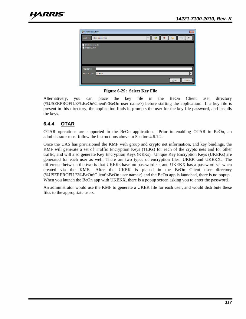
14221-7100-2010, Rev. K
117
Figure 6-29: Select Key File
Alternatively, you can place the key file in the BeOn Client user directory (%USERPROFILE%\BeOn\Client\<BeOn user name>) before starting the application. If a key file is present in this directory, the application finds it, prompts the user for the key file password, and installs the keys.
6.4.4 OTAR OTAR operations are supported in the BeOn application. Prior to enabling OTAR in BeOn, an administrator must follow the instructions above in Section 4.6.1.2.
Once the UAS has provisioned the KMF with group and crypto net information, and key bindings, the KMF will generate a set of Traffic Encryption Keys (TEKs) for each of the crypto nets and for other traffic, and will also generate Key Encryption Keys (KEKs). Unique Key Encryption Keys (UKEKs) are generated for each user as well. There are two types of encryption files: UKEK and UKEKX. The difference between the two is that UKEKs have no password set and UKEKX has a password set when created via the KMF. After the UKEK is placed in the BeOn Client user directory (%USERPROFILE%\BeOn\Client\<BeOn user name>) and the BeOn app is launched, there is no popup. When you launch the BeOn app with UKEKX, there is a popup screen asking you to enter the password.
An administrator would use the KMF to generate a UKEK file for each user, and would distribute these files to the appropriate users.

14221-7100-2010, Rev. K
118
7. PATCH AND SIMULSELECT CALLS
BeOn can participate in Patch and SimulSelect Calls as described in the following sections, but cannot create them. Patches and SimulSelects are created at the dispatch console.
7.1 SIMULSELECT FEATURE The SimulSelect feature allows a Console to talk simultaneously to a number of talkgroups. The BeOn devices in this case are basically passive receivers of a SimulSelect (SS) call from a Console. Devices cannot initiate an SS call nor talk back on the SS. Therefore, the talk back timer is not activated when a device is receiving a SimulSelect call regardless of its current setting. However, a SimulSelect call can be ignored by the device just like any other normal call. A SimulSelect call can be directed to a list of voice groups and/or individuals.
7.1.1 SimulSelect ICall When a BeOn device is receiving a SimulSelect call, then the call Status Bar displays the call information as if it was an ICall from the console to this device.
The Call Status Bar on the device displays a SimulSelect icon ( ) as well as an 'Ss' string indicating that this is a SimulSelect call. Since there could be multiple SimulSelects established on the same devices at the same time, each SimulSelect gets an assigned ID for this device. This ID has no meaning beyond the device; i.e., each device assigns its IDs independently from any other device. The call recipient is the registered device user. The call source is the contact associated with the Console ID. If a contact for the console originating the SimulSelect was never added to the Contacts on the device, then the ID (i.e., region/agency/user number) of the console is displayed.
7.1.2 SimulSelect Group Call When a BeOn device is receiving a SimulSelect call because it is scanning one or more groups that are part of the call, then the call Status Bar displays the call information as if it was a group call. If the BeOn device is scanning more than one group that is part of the SimulSelect call, then the call Status Bar displays the group information for the group with the highest priority.
The Call Status Bar on the device displays an icon ( ) as well as an 'Ss' string indicating that this is a SimulSelect call. The call recipient is the highest priority group scanned by the device that is part of this SimulSelect call. The call source is the contact associated with the Console ID.
7.1.3 BeOn Device Originated Group Calls While the BeOn device is part of SimulSelect, it can make normal group calls to any of its scanned groups including the groups that are part of the SimulSelect. Those calls are not affected by the contents of the SimulSelect.
7.2 PATCH FEATURE A patch allows temporary communications between a number of voice groups. Once the patch is set up, it can be used by either the console or the BeOn device to initiate calls. A Patch can only contain voice groups (no individuals). If a BeOn user selects a group that is part of a patch, then the call made on that group is always received by all members of the patch until the patch is torn down. The priority of the calls
NOTE

14221-7100-2010, Rev. K
119
to/from the Patch is the highest priority of a group contained in the patch in the BeOn device’s active profile.
7.2.1 Outgoing Call to a Patch
The patch icon ( ) is displayed for the rows of groups that are part of the patch. The call Status Bar displays the name of the selected group concatenated with the string "PatchA" that indicates that this call is going out on a patch. The ID "A" is device specific and is used to uniquely identify a patch on this device in case there are multiple patches active. The next call menu (lower left corner) displays the name of the group concatenated with “PatchA" to indicate that when PTT button is pressed the call will go out to the patch.
7.2.2 Incoming Patch Calls For incoming calls to a patch, the Status Bar always displays the highest priority group in the patch scanned by this device concatenated with the "Patch" and the patch ID specific to this device.
7.2.3 Talk Back Timer If the Talk Back timer is active and the next call group corresponds to one of the groups in the patch, the Talk Back timer is not displayed since the next call would go out to the patch anyway. However, if the next call is to a group outside of the patch, then the Talk Back timer is displayed to allow the user to call back on the patch.
7.3 PATCH/SIMULSELECT DISTRESS Addition of a group in distress to a patch or SimulSelect is prevented by the console.
If a tear down is initiated by the console on a SimulSelect and one of its groups is in distress, the tear down proceeds and the group's distress state is not affected.
Tear down of a patch while one of its groups is in distress is not allowed until the distress state of that group is cleared. When a distress is canceled on any group in the patch, it is canceled for the whole patch.
When a distress is initiated on a group that is part of a SimulSelect, it only affects that group. However, when a distress is initiated on a group that is in a patch, then the whole patch enters a distress state.

14221-7100-2010, Rev. K
120
8. ERROR MESSAGES This section provides information regarding error messages for the BeOn application. For other hardware or software failures, refer to the manufacturer’s documentation supplied with your device.
ERROR MESSAGE SOLUTION
You are not a member of any group
Appears in place of the list in the Groups tab when no profiles and groups have been assigned to a user’s personality. See your agency administrator to correct this.
No Next Call
Appears in bottom left of screen when scanning parameters haven’t been set at startup Verify that the phone’s data connection is established and working.
No Recent Calls Appears in the call Status Bar when there are no call events in the BeOn database.
Scan Parameters update failed Attempt to inform the VIDA system of current scan parameters failed. Verify that the phone’s data connection is established and working.
BeOn Application Failed to Start The BeOn application couldn’t initialize its internal components. Attempt to restart the application, or contact Harris TAC if this problem persists.
Registration timed out Attempt to register with the system failed. Verify that the phone’s data connection is established and working.
Request has timed out Attempt to inform the VIDA system of current scan parameters failed. Verify that the phone’s data connection is established and working.
Registration failed Attempt to register with the system failed. Verify that the phone’s data connection is established and working.
Invalid login credentials User identified in the license file is not a valid user in the system. Obtain a correct license from the agency administrator for the user.
You are logged in de-registered Registration couldn’t complete during initialization of the application. Verify that the phone’s data connection is established and working.
Active profile was not found The active profile couldn’t be initialized at startup. Contact Harris TAC for assistance.
Unstable network connection Attempt to inform the VIDA system of current scan parameters failed. Verify that the phone’s data connection is established and working.
Unread BeOn Notification(s)
Appears in the notification window when there are unprocessed BeOn notifications. Tap the top bar and drag downwards to expose the notifications window on mobile devices. Tap on the BeOn notification row to see the pending notifications.
Show group members request timed out
Attempt to get presence status for members of a group failed. Verify that the phone’s data connection is established and working.
Text Message Received
Appears when a BeOn text message is received by another user. Access the text message via the BeOn notifications screen or by viewing details of the Text Message event in the Events tab.

14221-7100-2010, Rev. K
121
ERROR MESSAGE SOLUTION
Send Failed A BeOn text message couldn’t be sent. Verify that the phone’s data connection is established and working.
UE Not Registered
A BeOn text message couldn’t be sent because the sender is not registered on the system. Verify that the phone’s data connection is established and working.
Dest Not Registered
A BeOn text message couldn’t be sent because the recipient is not registered on the system. Verify that the phone’s data connection is established and working.
Connection Error The VNIC could not be reached. Contact Harris TAC for assistance.
There are no distresses at the present time
Displayed in the Distress Status screen when the user and no groups are currently in distress state.
No external storage found. Please make sure external storage is mounted
Displayed when the BeOn application no longer detects the presence of an SD card. BeOn will shut down after confirmation of this message. BeOn cannot run without an SD card present in the device.
Location Request Failed
Attempt to get location from another user failed. Target user may not have GPS enabled on their device, or was unreachable at the time of the request.
<group> was placed in Distress state at <time>
Displayed in the notification details when a group is placed into distress state. <group> is the name of the group, and <time> is the time at which the distress was started.
Distress state for <group> was cleared at <time>
Displayed in the notification details when a group’s distress state is cleared. <group> is the name of the group, and <time> is the time at which the distress was started.
A number between <min> and <max> is required. Setting value to <default>
Displayed while modifying a value in the Preference screen when the value exceeds the allowable range. <min> is the minimum value, <max> is the maximum value, and <default> is the default value that gets applied after the message is confirmed.
Unable to retrieve presence state for
Attempt to get presence from another user failed. Target user may not exist in the presence database of the VNIC, or was unreachable at the time of the request.
Unsupported action: the group you selected is not in your current scan parameters
Chosen group cannot become the next call because it doesn’t exist in the current scanning parameter set. A profile containing the chosen group must be selected as the active profile prior to making the chosen group the next call.
RSI Mismatch: Please contact your crypto officer
The Radio Set Identifier (RSI) that the UE received from the UKEK load (via manual load or OTAR) is out of sync with the RSI that the UAS believes that the unit possesses. Contact the crypto officer to correct the key load.

14221-7100-2010, Rev. K
122
9. TECHNICAL ASSISTANCE The Technical Assistance Center's (TAC) resources are available to help with overall system operation, maintenance, upgrades and product support. TAC is the point of contact when answers are needed to technical questions.
Product specialists, with detailed knowledge of product operation, maintenance and repair provide technical support via a toll-free (in North America) telephone number. Support is also available through mail, fax and e-mail.
For more information about technical assistance services, contact your sales representative, or call the Technical Assistance Center at:
North America: 1-800-528-7711
International: 1-434-385-2400
Fax: 1-434-455-6712
E-mail: [email protected]
14221-7100-2010, Rev. J
123
APPENDIX A OPTIMIZING BATTERY LIFE The amount of power used by the device depends on the device type, the state of the battery, the other applications in use, and the amount of time sending and receiving communication over BeOn.
The following list provides guidelines for improving battery life while using BeOn.
• Screen
The number one consumer of battery life is the screen. It doesn't matter what application is running or even if you are on the OS home screen. Having the screen on significantly reduces your battery life.
Most smartphones can be set to reduce the brightness of the screen. This can extend the battery life significantly. Most smartphones allow you to change the background color. Changing it to a dark color is best, black is optimal.
Using a BeOn device with a PTT accessory and leaving the screen off is the best option.
• WiFi Use
BeOn requires a data connection - either cellular or WiFi. Most smartphones allow both to operate simultaneously. If you turn off WiFi, BeOn will connect over cellular. Turning off WiFi prevents the phone from using WiFi reception, and thus increases battery life.
• Closing Other Applications
Using BeOn while all other applications are closed will optimize battery life by preventing those applications from consuming battery power. In particular, media playback applications such as MP3 players and games will consume battery power quickly.
• GPS
Using location services consumes a lot of power. On Android, BeOn uses 25% more power with Location Services turned on. Many phones allow location services to use GPS satellites, the Wireless network, or both.
Disabling the GPS satellites for locations services can significantly extend the battery life of the BeOn device when "Share Location" is enabled. On the BeOn device, press the Settings button and clear the Share Location option.
If disabling GPS is not an option, decreasing the frequency of updates will also extend the battery life to some extent (see Section 4.4.9.4).
• Android GPS Controls
Press the Settings button and then tap Location Services. From here you can turn off several GPS options. Android devices may vary. Consult the documentation provided with your device.

14221-7100-2010, Rev. K
124
APPENDIX B VOICE ENCRYPTION IN BEON This section describes the process needed to configure and enable voice encryption for a BeOn user.
B.1 PREREQUISITES The following prerequisites are required to ensure the tools and system elements needed to configure and enable voice encryption for a BeOn user are present and available:
• The UAS and KMF are installed and configured.
• In the UAS, ensure the Key ID Ranges are defined under Region scope for System Admin.
Figure B-1: Key ID Range Settings in UAS
• The Region, Agency, talk groups, and users are configured in the UAS administration section.
• Enable Part 1025 in the KMF (refer to the KMF release notes, MS-008859-001).
• Install the BeOn client application(s).
B.2 UAS CONFIGURATION
B.2.1 Agency Administration Each end user in the administration system must have its “Enable P25 AES OTAR” setting set to “true.”
Figure B-2: Voice End User Settings in UAS

14221-7100-2010, Rev. K
125
If a subscriber unit has not been created for each BeOn user, create one and make sure the Protocol Type is “BeOn” (see Figure B-3).
Figure B-3: Subscriber Unit Settings in UAS
B.2.2 Crypto Officer Administration 1. Access the UAS as the Crypto Officer Administrator (COA) user and create a crypto officer:
Figure B-4: Crypto Officer Settings in UAS

14221-7100-2010, Rev. K
126
2. Next, create a KMF entry under the “KMFs” tab:
Figure B-5: KMF Settings in UAS
3. Add your agency(ies) to the Admin Class in use by the newly-created Crypto Officer (CO) to enable the CO to create crypto nets in which to add your BeOn Users:
Figure B-6: Admin Class Settings for Crypto Officer in UAS
4. Add the CO to the KMF created in step 2:
Figure B-7: KMF Settings in UAS

14221-7100-2010, Rev. K
127
5. Create crypto nets for end users and talk groups, utilizing the Key ID ranges added when you configured your agency:
Figure B-8: Crypto Net Settings in UAS
6. With the crypto net created, add your talk groups and end users to the crypto net:
Figure B-9: Talk Group and End User Settings in a Crypto Net

14221-7100-2010, Rev. K
128
7. Configuration of the data elements needed for voice encryption on the administration side is now complete. Issue a “Warm Start” on the users configured for voice encryption:
Figure B-10: Warm Start Operation in UAS
The configuration and setup in the UAS is now complete. The following steps involve the Key Management Facility (KMF) – specifically the Network KMF Management Console – and the BeOn clients.
B.3 KMF CONFIGURATION 1. Start the Network KMF Management Console application on the KMF server, and check the Event
Log to make sure there are no errors:
Figure B-11: Event Log in Network KMF Management Console

14221-7100-2010, Rev. K
129
2. Check the Task View tab to make sure the warm start process is complete:
Figure B-12: Task View Tab in Network KMF Management Console
3. On the End User tab, the user(s) that were just warm started should be listed and their respective crypto nets should be listed in the status area below the user list:
Figure B-13: End Users Tab in Network KMF Management Console
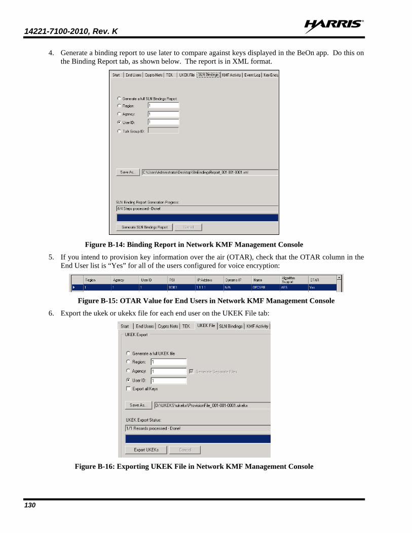
14221-7100-2010, Rev. K
130
4. Generate a binding report to use later to compare against keys displayed in the BeOn app. Do this on the Binding Report tab, as shown below. The report is in XML format.
Figure B-14: Binding Report in Network KMF Management Console
5. If you intend to provision key information over the air (OTAR), check that the OTAR column in the End User list is “Yes” for all of the users configured for voice encryption:
Figure B-15: OTAR Value for End Users in Network KMF Management Console
6. Export the ukek or ukekx file for each end user on the UKEK File tab:
Figure B-16: Exporting UKEK File in Network KMF Management Console
14221-7100-2010, Rev. K
131
7. With all the key files generated for the end users, transfer the files to the BeOn clients based on instructions found in Section 4.6.1.5 for Android clients, Section 6.4.3 for iOS clients, or Section 5.6.3 for Windows clients.
8. Verify that the key file was loaded successfully and that the BeOn client has successfully communicated with the KMF by accessing the Security Key Details screen in the client’s Preferences menu (see Section 4.4.9.6, Section 5.4.10.4, or Section 6.2.1.5).
B.4 TROUBLESHOOTING If “OTAR Enabled” is “No” or the “KMF Registered” fields are not what you expected, consider these troubleshooting tips:
1. Ping the KMF IP address from the LAP.
If not reachable, check firewall rules.
2. Warm Start Failed?
Check “Enable P25 AES OTAR” and “Manually-Keyed” options for the end user under agency administrator; one or the other should be checked, not both

14221-7100-2010, Rev. K
132
APPENDIX C MAPPING FAQ How do I set my location on the map (Windows Client only)? There are several ways to set your location on the map:
• During the initial setup wizard, enter the desired longitude and latitude.
• On the Map, right-click the desired location select “Set as Current Location.”
• On the Map tab of the Settings Dialog, enter the desired longitude and latitude.
On BeOn mobile clients, your location is determined automatically and cannot be set manually.
How do I prevent my location from being made available to other users? Windows Client
On the Map tab of the Settings Dialog, check “Hide My Location.” Your icon will no longer appear on the map and your name is displayed in italics on the Map indicating your location is being published as “unknown.”
iOS Client
Disable the control in the iOS Settings App, under Privacy/Location Services.
Android Client
Disable the control in the “Location Services” section of the Settings app.
How can I add a user to the map? Windows Client
There are several ways to add users to the map:
• On the ICall panel, right-click the Call Status Area and select “Add to Map,” or click the “Add to Map” tool button below the Call Status Area.
• On the Groups tab, right-click on a group member and select “Add to Map.”
• On the Contacts tab, right-click on a contact and select “Add to Map.”
• On the History tab, right-click an event and select “Add User to Map.”
iOS and Android Clients
Users can be added to the map from the slide out menu on the Map view. In addition, users can be added to the map in the iOS client from the Contacts menu.
How can I add multiple users to the map? You can add as many users as you like to the map by the methods described in the answer to “How can I add a user to the map?” Additionally, on the Groups tab and Contacts tab, select multiple users from the lists using the Shift and Ctrl keys (or press Ctrl-A to select all), then right-click a selected user and select “Add to Map.”
NOTE
14221-7100-2010, Rev. K
133
How can I add a group to the map? Windows Client
There are several ways to add groups to the map:
• On the Group panel, right-click the Call Status Area and select “Add to Map,” or click the “Add to Map” tool button below the Call Status Area.
• On the Profile panel, right-click a Call Status Area and select “Add to Map.”
• On the History tab, right-click a group event and select “Add Group to Map.”
iOS and Android Clients
Groups can be added to the map from the slide out menu on the Map view. In addition, users can be added to the map in the iOS client from the Groups menu.
How can I add multiple groups to the map (Windows Client only)? You can add as many groups as you like to the map by the methods described in the answer to “How can I add a group to the map?”
On the BeOn mobile clients, only a single group may be mapped at one time.
How do I remove users from the map? Windows Client:
On the Mapped Items panel (to the right of the map), select one or more users (multiple users may be selected with the Shift and Ctrl keys). Right-click on a selected user and select “Delete Item.”
You can never remove yourself from the map using the “Delete Item” menu.
iOS and Android Clients:
Remove users from the map using the slide out menu on the Map view.
How do I remove groups from the map? Windows Client:
On the Mapped Items panel (to the right of the map), select one or more groups (multiple groups may be selected with the Shift and Ctrl keys). Right-click on a selected group and select “Delete Item.”
iOS and Android Clients:
Remove groups from the map using the slide out menu on the Map view.
How do I subscribe to real-time location updates for users? Once a user has been added to the map, an icon is placed at his most recent location on the map. However, changes in his location (and presence) are not reflected until a subscription is made. To subscribe to the user’s location (and presence) updates, select one or more users on the Mapped Items panel (multiple users may be selected with the Shift and Ctrl keys). Right-click on a selected user and select “Subscribe.”
Because of system limitations, only 36 combined users and group subscriptions are available.
NOTE
14221-7100-2010, Rev. K
134
On BeOn mobile clients, mapping a user automatically results in subscribing to a real-time location for that user.
How do I subscribe to real-time group membership? Once a group has been added to the map, the members of the group are discovered and an icon is placed at each member’s most recent location on the map, if it’s known. However, changes in the group membership are not reflected until a subscription is made. To subscribe to a group’s membership, select one or more groups on the Mapped Items panel (multiple groups may be selected with the Shift and Ctrl keys). Right-click on a selected group and select “Subscribe.”
Because of system limitations, only 36 combined users and group subscriptions are available.
On BeOn mobile clients, mapping a group automatically results in subscribing to a real-time membership for that group.
How do I unsubscribe from real-time location updates for users? On the Mapped Items panel (to the right of the map), select one or more users (multiple users may be selected with the Shift and Ctrl keys). Right-click on a selected user and select “Unsubscribe.”
You cannot unsubscribe from yourself. A subscribed user does not have to be unsubscribed first in order to remove it; the delete action automatically makes them unsubscribed.
On the BeOn iOS Client, you must un-map the user to unsubscribe.
How do I unsubscribe from real-time group membership? Windows Client:
On the Mapped Items panel (to the right of the map), select one or more groups (multiple groups may be selected with the Shift and Ctrl keys). Right-click on a selected group and select “Unsubscribe.”
A subscribed group does not have to be unsubscribed first in order to remove it; the delete action automatically makes it as well its users unsubscribed.
iOS and Android Clients:
On mobile clients, un-map the group to unsubscribe.
NOTE
NOTE
NOTE
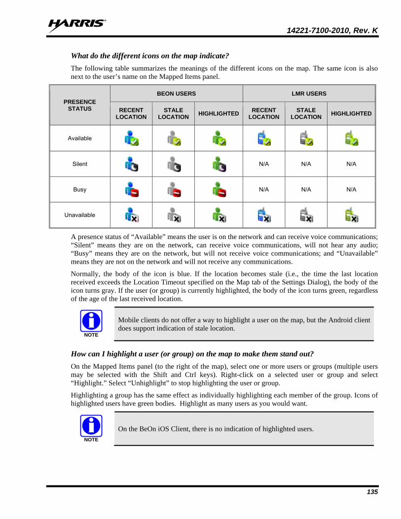
14221-7100-2010, Rev. K
135
What do the different icons on the map indicate? The following table summarizes the meanings of the different icons on the map. The same icon is also next to the user’s name on the Mapped Items panel.
PRESENCE STATUS
BEON USERS LMR USERS
RECENT LOCATION
STALE LOCATION HIGHLIGHTED RECENT
LOCATION STALE
LOCATION HIGHLIGHTED
Available
Silent
N/A N/A N/A
Busy
N/A N/A N/A
Unavailable
A presence status of “Available” means the user is on the network and can receive voice communications; “Silent” means they are on the network, can receive voice communications, will not hear any audio; “Busy” means they are on the network, but will not receive voice communications; and “Unavailable” means they are not on the network and will not receive any communications.
Normally, the body of the icon is blue. If the location becomes stale (i.e., the time the last location received exceeds the Location Timeout specified on the Map tab of the Settings Dialog), the body of the icon turns gray. If the user (or group) is currently highlighted, the body of the icon turns green, regardless of the age of the last received location.
Mobile clients do not offer a way to highlight a user on the map, but the Android client does support indication of stale location.
How can I highlight a user (or group) on the map to make them stand out? On the Mapped Items panel (to the right of the map), select one or more users or groups (multiple users may be selected with the Shift and Ctrl keys). Right-click on a selected user or group and select “Highlight.” Select “Unhighlight” to stop highlighting the user or group.
Highlighting a group has the same effect as individually highlighting each member of the group. Icons of highlighted users have green bodies. Highlight as many users as you would want.
On the BeOn iOS Client, there is no indication of highlighted users.
NOTE
NOTE

14221-7100-2010, Rev. K
136
How can I hide a user (or group) on the map? Hiding a group has the same effect as individually hiding each member of the group. Hidden users are not displayed on the map. You may hide as many users and groups as you would like.
Hiding a user is helpful when watching groups on the map that have members far away from the rest of the group. The calculated zoom level when centering the map on a group does not take into account hidden users.
Windows Client:
On the Mapped Items panel (to the right of the map), select one or more users or groups (multiple users may be selected with the Shift and Ctrl keys). Right-click on a selected user or group and select “Hide.” Select “Show” to show the user or group.
iOS and Android Clients:
Hide users using the slide out menu on the Map view.
How can I center the map on a user? Windows Client:
There are several ways to center the map on a user:
• On the Map, right-click the user and select “Set As Center.”
• On the Mapped Items panel, double click on the user, or right-click on the user and select “Set As Center.”
• Add the user to the map again by any of the methods described in the answer to “How can I add a user to the map?”
The zoom level is preserved when centering on a user.
iOS Client:
Tap on the Arrow icon at the bottom left of the Map view to center the map on your location. Tap the one-person icon in the bottom right corner of the map to center the map to your location.
iOS and Android Clients:
The map will automatically re-center on your location as it changes, until you manually zoom or shift the map view, or you choose to center on the group. There is no support for automatically centering the map on another user.
How can I center the map on a group? Windows Client:
On the Mapped Items panel, right-click on the group and select “Set As Center.” The map will change zoom level and pan to show all group members.
iOS Client:
Tap the Group icon at the bottom left of the Map view to scale and center the map and display all the currently mapped users or group.
Android Client:
Tap the group icon in the bottom left corner to scale and center the map and display all the currently mapped users or group.

14221-7100-2010, Rev. K
137
iOS and Android Clients:
The map will automatically re-center and re-scale as locations are changed, until you manually zoom or shift the map view, or you choose to center on the your location.
What do the various text formats mean in the Mapped Items panel (Windows Client only)? The Mapped Items panel uses color, italics, and a bullet character to convey information about users’ location, real-time subscription status, and visibility on the map. The table below summarizes the various formats currently in use.
MAPPED ITEMS PANEL FORMAT REAL-TIME SUBSCRIPTION
LOCATION KNOWN
SHOWN ON MAP
John Smith ● Y Y Y
John Smith ● Y N N
John Smith N Y Y
John Smith N N N
John Smith ● Y n/a N
John Smith N n/a N
Not supported on BeOn mobile clients.
What happens when a mapped user places a call? When transmitting a PTT or receiving a PTT from a mapped user, flashing blue circles (radio waves) are drawn around the user’s icon as show in the following image.
What happens when a mapped user places a distress call? When transmitting a distress PTT or receiving a distress PTT from a mapped user, flashing red circles (radio waves) are drawn around the user’s icon as show in the following image.
NOTE

14221-7100-2010, Rev. K
138
How are users who have initiated a distress displayed on the map? When a user places a distress call, either because he initiated a distress or because he is talking on a group which has been placed in distress, his icon on the map will change as described in the answer to “What happens when a mapped users places a distress call?” His icon will not be displayed any differently if he is not transmitting.
What happens when a mapped user stops scanning the group under which he’s mapped? When you’re real-time subscribed to a group and a user stops scanning that group, he is removed from the group membership and removed from the map. However, if the user has been individually added to the map, he is only removed from the group membership, but continues to be displayed on the map.
On the BeOn mobile clients, the user is removed from the map immediately after being removed from the group, unless that user is mapped explicitly with the “Map Contacts” action.
What happens when a mapped user deregisters? When you’re real-time subscribed to a user and he deregisters, either deliberately or due to poor network coverage, his presence changes to unavailable, but he continues to be shown as a group member and shown on the map.
On BeOn mobile clients, the user is removed from the map once they deregister from the system, but the icons may remain on the map if they lose their data connection or exit BeOn in an unexpected way (e.g., battery loss).
Why do I see location, presence, or group membership change, without having made a real-time subscription? Sometimes real-time subscriptions are made in the background to support other feature of the application (e.g., the Group tab membership list). Events cause by those subscriptions affect all areas of the application.
Why must I real-time subscribe to groups and users after adding them to the map? Due to system limitations, only a limited number of real-time subscriptions (approximately 38) can exist for the application at any time. With group size variability and subscriptions needed for group membership, this limit could be exhausted quickly. To provide the greatest flexibility and allow complete control over what appears on the map, you must specify precisely which users and groups you want to track.
How can I remove my user’s icon from others’ maps (e.g., at the end of my shift)? To remove your icon from other’s maps, stop scanning the groups that are being mapped or sign out of BeOn. If a BeOn Windows Client is mapping the user as part of the group only, the user is removed from the map and the Mapped Items panel. However, if the user is mapped as an individual, they remain on the map. The rationale for this is that mapped individuals have higher precedence and shouldn’t be removed from a map due to someone’s remote action.
In earlier releases of the Windows Client (before R2A), users were NOT removed from the map if they signed out. Instead their icon was changed to “Unavailable.”
NOTE
NOTE

14221-7100-2010, Rev. K
139
Alternatively, check the “Hide My Location” checkbox on the Map Tab of the Settings Dialog and then click Save. This may not affect the remote clients immediately; however, the next time that the remote client attempts to map you, it will not have a valid location, and therefore will not be able to do so.
On the BeOn iOS Client, you must stop scanning the groups that are being mapped or sign out of BeOn. Alternatively, you may hide your location as explained previously.
NOTE

14221-7100-2010, Rev. K
140
APPENDIX D ABBREVIATIONS AND ACRONYMS
Table D-1: Abbreviations and Acronyms
Abbreviation Description 3G Third Generation Wireless Systems 4G Fourth generation of the cellular wireless standard APN Access Point Name BCI BeOn Client Installer COTS Commercial Off-The-Shelf DTM Dual Transmission Mode EDGE Enhanced Data Rates for Global Evolution EULA End User Licensing Agreement GPRS General Packet Radio Services GSM Global System for Mobile communication ISP Internet Service Provider LAP LMR Access Point LAS LMR Assignment Server LMR Land Mobile Radio LTE Long Term Evolution, also known as 4G MSP Managed Service Provider OS Operating System PMR Private (or Professional) Mobile Radio (see LMR) PTT Push-To-Talk SMS Short Message Service SPS Software Provisioning Server SU Subscriber Unit (also see UE) UAS Unified Administration System UE User Equipment VIDA Voice, Interoperability, Data, and Access
VNIC VIDA Network Interconnect (VIDA audio switch) VoIP Voice over IP WCDMA Wideband Code Division Multiple Access XML eXtensible Markup Language

14221-7100-2010, Rev. K
141
APPENDIX E TROUBLESHOOTING E.1 LOG FILES
The BeOn app on Android, by default, writes a limited amount of information to its log files. The following files are created by the Android app for purposes of further analysis should the need arise:
• beonptt.log – primary log file
• beonptt.log.1
• beonptt.log.2
All log files are stored in the app’s private storage area. They can be retrieved and sent via email using the “Send Logs” option in the BeOn Preferences screen:
Selecting this option presents the user with various email-based options. The user should add detail to the email as to what was happening when the problem occurred and any other information that would inform the BeOn team during their analysis:
The email is sent directly to the BeOn team and, in most cases, a Harris Technical Assistance Center (TAC) case will be opened to track the issue.

14221-7100-2010, Rev. K
142
E.2 DEBUG LEVEL The Android app also allows the user to adjust the logging level of various components in the app. This allows the app to output more information based on the nature of the problem. Access the “Development Preferences” screen by tapping the blank space below the “License Agreement” button on the About screen. From here, you can adjust log levels.
The About screen can be accessed either from the Sign In screen or in the Preferences screen.
Once in the “Development Preferences” screen, you can adjust various components of the BeOn PTT app:
For each of these components, the log level can be adjusted. The default is INFO but can be changed to other levels, thereby increasing the amount of output in the log files. For instance, the “CallProcessor” component is related to the processing of all types of PTT calls:

14221-7100-2010, Rev. K
143
Adjusting the level to “Debug” or “Trace” increases the level of logging for the CallProcessor component. To ensure the right logging is captured for the issue or question at hand, consider adjusting the components based on the associated categories listed below:
CATEGORY COMPONENTS
App Startup
DataUpgrade DataProcessor DatabaseHandler MainActivity MainApplication TabControl TabControlCommon
Registration/Deregistration
BeOnPersonality MobilityProcessor P3000Factory UIBeOnEventBroadcaster OutputSubsystem
PTT CallProcessor P3000Factory UIBeOnEventBroadcaster
Distress CallProcessor EmergencyManager
Encryption KeyMgmtProcessor KmtLibImpl P1006Factory
Presence/Location
BeOnLocation DeviceLocationService LocationUpdater P3000Factory UIBeOnEventBroadcaster UserServicesProcessor

14221-7100-2010, Rev. K
144
CATEGORY COMPONENTS
Mapping
AbstractMapGenerator GoogleM4BMapGenerator HomeTab MapActivityHelper
Text Messaging UserServicesProcessor P1014Factory
PTT Audio/Tones AudioPlayer AudioRecordingThread P25VoiceFormatter
Once you have adjusted the correct components, attempt to reproduce the problem and use the “Send Logs” option to send the logs.

14221-7100-2010, Rev. K
145
This page intentionally left blank.

About Harris Corporation
Harris Corporation is a leading technology innovator that creates mission-critical solutions that connect, inform and protect the world. The company’s advanced technology provides information and insight to customers operating in demanding environments from ocean to orbit and everywhere in between. Harris has approximately $8 billion in annual revenue and supports customers in 125 countries through four customer-focused business segments: Communication Systems, Space and Intelligence Systems, Electronic Systems, and Critical Networks.
FLORIDA NEW YORK VIRGINIA BRAZIL UNITED KINGDOM UAE SINGAPORE