user’s manual ikuma - niviuk-gliders · manual ikuma. 2 niviuk gliders & air ... that you...
TRANSCRIPT

USER’S MANUALIKUMA
2
NIVIUK GLIDERS & AIR GAMES SL C/ DEL TER 6, NAVE D 17165 LA CELLERA DE TER - GIRONA - SPAIN
TEL. +34 972 42 28 78 FAX +34 972 42 00 86
[email protected] www.niviuk.com
IKUMA
Without shortcuts
WELCOME
We wish to welcome you to our team and thank you for the confidence that you have placed in a NIVIUK Glider.
We would like to share with you the commitment, the passion and emotions of the Niviuk design team, which have resulted in the creation of the new IKUMA. Niviuk are very proud of this new glider, a glider carefully designed to bring you maximum pleasure whilst allowing you learn and progress.
We are confident that you will enjoy flying this wing and that you will soon understand the meaning of our slogan:“The importance of small details”
This is the user’s manual that we recommend you to read in detail.
The NIVIUK Gliders Team.
USER’S MANUAL
NIVIUK Gliders IKUMA
This manual offers all the necessary information that will familiarize you with the main characteristics of your new paraglider. Although this manual informs you about your glider, it does not offer the instruction requirements necessary for you to be able to pilot this type of wing. Flying instruction can only be taught at a paragliding school recognized by the Flying Federation of your country.
Nevertheless we remind you that it is important that you carefully read all the contents of the manual for your new IKUMA.
Severe injuries to the pilot can be the consequence of the misuse of this equipment.

3
SUMMARY
WELCOME 2
USER’S MANUAL 2
1. CHARACTERISTICS 4
1.1 WHO IS IT DESIGNED FOR? 4
1.2 CERTIFICATION 4
1.3 IN-FLIGHT BEHAVIOR 4
1.4 ASSEMBLY, MATERIALS 4
2. UNPACKING AND ASSEMBLY 6
2.1 CHOOSE THE RIGHT PLACE 6
2.2 PROCEDURE 6
2.3 ASSEMBLY TO THE HARNESS 6
2.4 TYPE OF HARNESS 6
2.5 ASSEMBLY OF THE ACCELERATOR 6
2.6 INSPECTION AND WING
INFLATION ON THE GROUND 7
2.7 ADJUSTING THE BRAKES 7
3. THE FIRST FLIGHT 7
3.1 CHOOSE THE RIGHT PLACE 7
3.2 PREPARATION 7
3.3 FLIGHT PLAN 7
3.4 PRE-FLIGHT CHECK LIST 7
3.5 WING INFLATION, CONTROL
AND TAKE-OFF 7
3.6 LANDING 8
3.7 FOLDING INSTRUCTIONS 8
4. IN FLIGHT 8
4.1 FLYING IN TURBULENCE 8
4.2 POSSIBLE CONFIGURATIONS 8
4.3 USING THE ACCELERATOR 10
4.4 FLYING WITHOUT BRAKE LINES 10
4.5 KNOTS IN FLIGHT 10
5. LOSING HEIGHT 11
5.1 EARS 11
5.2 4B2 TECHNIQUE 11
5.3 B-LINE STALL 11
5.4 SPIRAL DIVE 12
5.5 SLOW DESCENT TECHNIQUE 12
6. SPECIAL METHODS 12
6.1 TOWING 12
6.2 ACROBATIC FLIGHT 12
7. CARE AND MAINTENANCE 13
7.1 MAINTENANCE 13
7.2 STORAGE 13
7.3 CHECKS AND CONTROLS 13
7.4 REPAIRS 13
8. SAFETY AND RESPONSIBILITY 13
9. GUARANTEE 13
10. TECHNICAL DATA 15
10.1 TECHNICAL DATA 15
10.2 MATERIALS DESCRIPTION 16
10.3 ARRANGEMENT ARRANGEMENT 17
10.4 LINE PLAN 18
10.5 LENGTHS IKUMA 21 19
10.6 LENGTHS IKUMA 23 19
10.7 LENGTHS IKUMA 25 20
10.8 LENGTHS IKUMA 27 20
10.9 LENGTHS IKUMA 29 21
10.10 CERTIFICATION SPECIMEN TEST 22

4
1. CHARACTERISTICS
1.1 WHO IS IT DESIGNED FOR?
The IKUMA has been designed for those pilots who want to improve their flying skills. This glider opens the door to the world of cross country for those pilots seeking to improve their performance without compromising safety.
The IKUMA has a completely new design compared with all the other Niviuk gliders. A new concept designed for those pilots who want a new category glider to practice Cross Country without thinking in nothing else than enjoying. It has a very good passive safety and easy piloting. Sportier than a standard EN B glider and less demanding than an EN C, but with its same high performance.
The IKUMA has a better gliding. Its aspect ratio has been increased and its profile has been designed to become a faster glider. It has less air resistance due to his new and optimized suspension line structure. All these improvements in the new IKUMA, have been made with the latest materials and the best innovation technologies based on the competition gliders to provide the best performance to our pilots.
1.2 CERTIFICATION
The IKUMA has successfully achieved the European EN/LTF certification. This test was carried out in the Swiss Air-Turquoise laboratories in Switzerland.All the commercially available sizes passed every required test with excellent results and the IKUMA received EN B / LTF B certification for all sizes.
The IKUMA passed the essential load test of 8g without experiencing any problems.
We recommend paying special attention on the flight test report made by the certification laboratory, and specially attention to the test pilot comments (Point 25 on the flight test report).On the flight test report there is all necessary information to know how the new paraglider will react on each maneuver tested.It is important to take into account that each size can have a different reaction on the same maneuver. Furthermore, the same size on maximum load o minimum load can experiment a different behavior.
Check the certification results and figures on the last pages of this manual or at www.niviuk.com
1.3 IN-FLIGHT BEHAIVOR
With progressive, predictable and efficient handling the IKUMA effectively reads the air mass, seeking out and coring thermals with efficiency and ease. The IKUMA remains agile, light and predictable in all conditions of flight and behaves impeccably during turbulence.
The IKUMA was designed with the latest innovations in materials and technologies, and that aspect provides the glider with a better performance in all phases of flight.
With an aspect ratio of 5.7 it is a 3 liner profile that provides clear and useful information to the pilot; it situates itself into the centre of the thermal or it follows the ascendant air flow. Its air entrances have been replaced, so the application of the RAM Air Intake turns the leading edge in a powerful and key element to its performance. While flying the IKUMA the pilot feels that can reach his full potential.If you already are a Niviuk pilot the improvements of the IKUMA will surprise you. If this is the first time you pilot one Niviuk glider, just enjoy it!
1.4 ASSEMBLY, MATERIALS
The IKUMA has all the technological innovations as used on other Niviuk

5
gliders. Furthermore it is full of small details destined to enhance the pilots’ comfort and to improve the performance of the SLE, RAM, DRS, TNT and 3 line profile.
The use of the SLE (Structured Leading Edge) allows reinforcement of the leading edge preventing any deformation during turbulence. The airflow is also vastly improved over the entire front span of the glider.(See http://niviuk.com/technology.asp?id=JNKPKPN4)
The RAM AIR INTAKE technology presents an internal positioning for the air entrance to allow an optimal maintenance of the internal pressure as well as an improving of the laminar flow on intrados. What’s the result?Gaining turbulent air absorption in the leading edge, more consistent at every speed and a better performance while assuring maximum security.(See http://www.niviuk.com/technology.asp?id=JNKQKNP4)
DRS.-The trailing edge has been reinforced with small ribs that make this part flatter in order to spread the pressure out evenly. It means better air-flow and less drag on this important part of the glider. The addition of these ribs gives exceptional handling (better and more efficient when turning) and more control and precision.
TNT.- It is a technical revolution. It underlines building the internal structure of the glider with Nitinol to make the profile more uniform and the glider lighter for better flight performance. Moreover, the Nitinol is resistant to deformations, hot temperatures and breaks as well as more resistant to the glider folding process.
3LT.-Its powerful profile, a detailed internal architecture structure and the use of high-tech strength materials make possible a significant reduction of the total length of suspension lines in order to reduce the parasite resistance and the weight of the glider to gain efficiency.
Not a single millimeter of error is possible in the manufacturing process from Olivier’s computer to the cutting of the fabric. An automatic process
controlled by a laser-cutting program cuts each of the sections that compose the different parts of the wing. This program not only cuts the pieces of fabric but it also paints the guideline marks that will aid the assembly; it also numbers the separate pieces of material. All this is carried out before human handling of the pieces begins. So we eliminate possible and understandable errors that may occur during this delicate procedure.
The lines are semi-automatically manufactured and all the sewing is finished under the supervision of our specialists. The jigsaw puzzle of the assembly process is made easier using this method. We minimize the processes while making the quality control more efficient. All the different parts of the canopy are cut and assembled under the strict conditions induced by the automation of the whole process. It is strongly recommended that all lines are thoroughly checked by the pilot prior to every flight and ultimately checked by a service centre or Niviuk dealer after every 100 hours of flight. We should not forget that we are using materials with great performance but that they need a rigorous check before every flight.
All NIVIUK Gliders go through an extremely thorough and efficient final inspection.Every single line of each glider is measured individually once the final assembly has concluded. Each wing is then individually inflated for the last visual revision.
Each glider is packaged following the maintenance and conservation instructions recommended for the advanced materials. NIVIUK Gliders are made of first class materials as demanded by the performance, durability, and homologation requirements of the present-day market.
Information about construction materials is given on the last pages of this manual.

6
2. UNPACKING AND ASSEMBLY
2.1 CHOOSE THE RIGHT PLACE
We recommend that you unpack and assemble your wing on a schooling slope or a flat clear area without too much wind and free of obstacles. These conditions will allow you to carry out all the steps required for you to check and inflate the IKUMA.
We recommend that an instructor or a retailer supervises the entire procedure as only they are competent to resolve any doubt in a safe and professional way.
2.2 PROCEDURE
Take the paraglider out of the rucksack, open it and spread it open with the lines on top of the underside, position the wing as if you were to inflate it. Check the condition of the fabric and the lines, making sure there are no abnormalities. Check the maillons, which attach the lines to the risers, are properly closed. Identify and if necessary disentangle the lines from A, B’, B and C risers, the brake lines and the corresponding risers. Make sure that there are no ties or knots.
2.3 ASSEMBLY OF THE HARNESS
Correctly place the risers on the harness karabiners. The risers and lines should not have any twists and they should be in the right order. Check that the harness buckles are correctly locked.
2.4 TYPE OF HARNESS
The IKUMA has been certified on EN B with a harness according to the following rules:
• 2. DV LuftGerPV §1, Nr. 7 c (LTF)
• European Standard EN1651• European Standard EN12491
This certification allows it to be flown with most of the harnesses on the market, even the ones that use cocoon. We strongly recommend that you adjust the distance of the chest strap according the values used during certification. This varies according to the size of the chosen harness.
Small = 44 cmMedium = 45 cmLarge = 46 cm
Incorrect adjustment can seriously affect the piloting of the glider. A distance, which is too wide between the karabiners, may provide more feedback but could affect the overall stability of the glider. A distance, which is too narrow between the karabiners, would provide less feedback but also increase any risk of developing a twist in during a large collapse.Any change made to these specifications may affect the wing’s performance and reactions. This would therefore effect the glider’s configuration and would not conform to the homologation.
2.5 ASSEMBLY OF THE ACCELERATOR
The acceleration mechanism of the IKUMA works when you push with your feet on the accelerator bar, this is supplied with the equipment. On delivery the accelerator bar has not yet been installed and it is recommended that it is fit by yourself before flight.
Most harnesses are equipped with a pre-installed acceleration system. When fitting any accelerator system ensure that all preinstalled items within the harness, such as roller pulleys are used correctly. After fitting, take into account that you will have to adjust the length of the accelerator lines for correct use. This will vary according to the length of the pilot’s legs!

7
We recommend that you try the correct fitting of the acceleration system on equipment designed to do this, most paragliding schools have this sort of equipment.
2.6 INSPECTION AND WING INFLATION ON THE GROUND
Once you have checked all the equipment and made sure that the wind conditions are favorable, inflate your IKUMA as many times as necessary in order to become acquainted with the wing’s behavior. The IKUMA inflates easily and smoothly. An excess of energy is not necessary and the wing will inflate with minimum pressure on the harness when you move forward. This may be assisted by using the A lines. Do not pull on them; just accompany the natural rising movement of the wing. Once the wing is in the 12 o’clock position, simply apply correct pressure on the brake lines and the IKUMA will sit over your head.
2.7 ADJUSTING THE BRAKES
The length of the main brake lines is adjusted at the factory to the length established during certification. However, the length can be changed to adapt to the pilot’s flying style. Nevertheless, we recommend that you fly for a while with these, set at the original length. This will allow you to become accustomed to the IKUMA and its unique flying behavior. If you then decide to change the length of the brake lines, untie the knot, slide the line through the brake link to the desired length, and strongly re-tie the knot. Qualified personnel should carry out this adjustment. You must ensure that this adjustment does not slow down the glider without any pilot input. Both brake lines should be symmetrical and measure the same length. The most recommended knots are the clove hitch knot or bowline knot.
When changing the brakes length, it is necessary to check that they do not act when the accelerator is used. When we accelerate the glider rotates over the C riser and the trailing edge elevates. We must check that the brake is adjusted taking in consideration this extra length in acceleration.
3. THE FIRST FLIGHT
3.1 CHOOSE THE RIGHT PLACE
We recommend that the first flight with your IKUMA is made on a smooth slope (a school slope) or in your usual flying area.
3.2 PREPARATION
Repeat the procedures detailed in chapter 2 UNPACKING AND ASSEMBLY in order to prepare your equipment.
3.3 FLIGHT PLAN
Draw out a flight plan before take-off in order to avoid possible flight errors.
3.4 PRE-FLIGHT CHECK LIST
Once you are ready, but before you take-off, carry out another equipment inspection. Ensure correct installation of all equipment and that all lines are free of hindrances or knots. Check that the weather conditions are suited for your flying skills.
3.5 WING INFLATION, CONTROL AND TAKE-OFF
Smoothly and progressively inflate the wing (chapter 2.6 INSPECTION AND WING INFLATION ON THE GROUND). The IKUMA inflates easily and does not require excessive energy. It does not tend to over-take you, so the wing inflation phase is carried out without anguish. These take off characteristics provide a perfect control phase and enough time for the pilot to decide whether to accelerate and take off.
Whenever the wind speed allows it, we recommend a reverse launch technique; this type of launch allows you to carry out a better visual

8
check of the wing. The IKUMA is especially easy to control in this position in strong winds. However, wind speeds up to 25 to 30 km/h are considered strong and extra consideration should be given to any thought of flight.
Preparation and positioning of the wing on the take-off is especially important. Choose a location which is appropriate for the direction of the wind. Position the paraglider as if it were part of a large circle, taking into account the shape of the canopy in flight. All this will assist in a trouble free take-off.
3.6 LANDING
The IKUMA lands excellently, it transforms the wing speed into lift on the pilot’s demand, allowing an enormous margin of error. You will not have to wrap the brake lines around your hand to get greater braking efficiency.
3.7 FOLDING INSTRUCTIONS
The IKUMA has a complex leading and trailing edge, manufactured using a variety of different materials. For that reason, the use of a correct folding method is very important for extending the useful life of your paraglider. It should be folded like an accordion, with the leading edge reinforcements flat and the nylon sticks positioned one upon the other. This method will ensure that the profile remains in good shape without altering its form or its performance.
The wing should then be folded in three parts. The wing does not have to be tightly folded, if you do so it may damage the material and or the lines.
4. IN FLIGHT
4.1 FLYING IN TURBULENCE
The IKUMA has an excellent profile to withstand the very different aero-logical conditions so allowing the best possible piloting and stability. It reacts admirably in passive flight, thus offering a high level of safety in turbulent conditions. Nonetheless, the pilot always has to pilot according to the prevailing weather conditions, the pilot is the ultimate safety factor.
We recommend active piloting, making the necessary fine adjustments to keep the wing in control. He/she should stop braking to allow it to fly at the required wing speed after a correction is made. Do not maintain any correction for longer than necessary (braked) this would cause the wing to enter into critical flying situation. Whenever necessary, control a situation, react to it and then re-establish the required speed.
4.2 POSSIBLE CONFIGURATIONS
We recommend that training to master these maneuvers be carried out under the supervision of a competent school.
Asymmetric collapse
In spite of the stability of the profile of the IKUMA, heavy turbulent conditions may cause part of the wing to collapse asymmetrically. This usually happens when the pilot has not foreseen this possible reaction of the wing. When the wing is about to experience an asymmetric collapse the brake lines and the harness will transmit a loss of pressure to the pilot. To prevent the collapse from happening, pull the brake line corresponding to the compromised side of the wing, this will increase the angle of incidence. If the collapse does happen the IKUMA will not react violently, the turn tendency is very gradual and it is easily controlled. Lean your body towards the side that is still flying in order to counteract the turn and to maintain a straight course, if necessary slightly slow down the same side. The collapse will normally open by itself but if that does not happen, pull completely on the brake line on the side, which has collapsed (100%). Do this with a firm movement. You may have to repeat this operation to

9
provoke the re-opening. Take care not to over-brake on the side that is still flying (turn control) and when the collapse has been solved; remember to let the wing recover its flying speed.
Symmetric collapse
In normal flying conditions the design of the IKUMA ensures that a symmetric collapse is quite improbable. The profile of the wing has been designed to widely tolerate extreme changes in the angle of incidence. A symmetric collapse may occur in heavy turbulent conditions, on entry or exit of strong thermals or lack of adapting the use of the accelerator to the prevailing air conditions. Symmetrical collapses usually re-inflate without the glider turning but you can symmetrically apply the brake lines with a quick deep pump to quicken the re-inflation. Release the brake lines immediately to recover optimum flight speed.
Negative spin
This configuration is out of the normal flight behavior of the IKUMA. Certain circumstances however, may provoke this configuration such as trying to turn when the wing is flying at very low speed (while heavily braking). It is not easy to give any recommendations about this situation since it varies depending on the circumstances. Remember that you should restore the relative air speed over the wing. To achieve this, progressively reduce the pressure on the brake lines and let the wing gain speed. The normal reaction would be a lateral surge with a turn tendency no greater than 360º before restoring to normal flight conditions.
Parachutal stall
If it does happen, the feeling would be that the wing would not be advancing; you would feel a kind of instability and a lack of pressure on the brake lines, although the canopy would appear to be correctly inflated. The correct reaction would be to release the pressure on the brake lines and push the A lines forward or rather lean your body to any
side WITHOUT PULLING ON THE BRAKE LINES.
Deep stall
The possibility of the IKUMA falling into this configuration during normal flight is very unlikely. This could happen if you are flying at a very low speed, whilst over steering in a number of maneuvers and in turbulent conditions. To provoke a deep stall you have to take the wing to minimum flight speed by symmetrically pulling the brake lines, when you reach this point, continue pulling until you reach 100% and then hold. The glider will first fall behind you and then situate itself above you, rocking slightly, depending on how the maneuver was carried out. When you start to provoke a stall, be positive and do not doubt an instant. Do not release the brake lines when half way through the maneuver. This would cause the glider to surge violently forward with great energy and may result in the wing below the pilot. It is very important that the pressure on the brake lines is maintained until the wing is well established vertical above.To regain normal flight conditions, progressively and symmetrically release the brake lines, letting the speed be re-established. When the wing reaches the maximum advanced position ensure that the brakes are fully released. The wing will now surge forward, this is necessary so that air speed is completely restored over the wing. Do not over brake at this point because the wing needs to recover speed to quit the stall configuration. If you have to control a possible symmetrical front stall, briefly and symmetrically pull on the brake lines and let go even when the wing is still ahead of you.
Wing tangle
A wing tangle may happen after an asymmetric collapse, the end of the wing is trapped between the lines (Cravat). This situation could rapidly cause the wing to turn, although it depends on the nature of the tangle. The correction maneuvers are the same as those applied in the case of an asymmetrical collapse, control the turn tendency by applying the opposite brake and lean your body against the turn. Then locate the line that

10
reaches the stabilizer that is trapped between the other lines. This line has a different color and belongs to the external lines of the Criser.
Pull on this line until it is tense, this should help to undo the wing tangle. If you cannot undo the tangle, fly to the nearest possible landing spot, control the flying course with your body movements and a little pressure on the opposite brake. Be careful when attempting to undo a tangle if you are flying near a mountainside or near to other paragliders, you may lose control of the flying course and a collision may occur.
Over handling
Most flying incidents are caused by incorrect actions of the pilot, which chained one after another creates abnormal flying configurations (a cascade of incidents). You must remember that over handling the wing will lead to critical levels of functioning. The IKUMA is designed always to try to recover normal flight by itself, do not try to over handle it.Generally speaking, the reactions of the wing, which follow over handling, are neither due to the input made or the intensity, but the length of time the pilot continues to over handle. You have to allow the profile to re-establish normal flight speed after any type of handling.
4.3 USING THE ACCELERATOR
The profile of the IKUMA has been designed to fly stable through its entire speed range. It is useful to accelerate when flying in strong winds or in extreme descending air. When you accelerate the wing, the profile becomes more sensitive to possible turbulence and closer to a possible frontal collapse. If you feel a pressure loss, you should release the pressure on the accelerator and pull slightly on the brake lines to increase the angle of incidence. Remember that you have to re-establish the flight speed after correcting the incidence.
It is NOT recommended to accelerate near to the mountainside or in very turbulent conditions. If necessary you will have to constantly adjust the
movements and pressure on the accelerator whilst constantly adjusting the pressure applied to the brake lines. This balance is considered to be “active piloting.”
The IKUMA risers have been designed without any adjustable, removable or variable device to prevent and incorrect use of the accelerator system.
4.4 FLYING WITHOUT BRAKE LINES
If, for any reason at all, you cannot use the brake lines of your IKUMA you will have to pilot the wing using the C-risers and your body weight to fly towards the nearest landing. The C-lines steer easily because they are not under pressure, however you have to be careful not to over handle them causing a stall or negative turn. To land you have to let the wing fly at full speed and before reaching the ground you will have to pull symmetrically on both the C-risers. This braking method is not as effective as using the brake lines so you will land at a higher speed.
4.5 KNOTS IN FLIGHT
The best way to avoid these knots and tangles is to inspect the lines before you inflate the wing for take-off. If you notice a knot before take-off, immediately stop running and do not take-off.If you have taken-off with a knot you will have to correct the drift by leaning on the opposite side of the knot and apply the brake line on that side too. You can gently try to pull on the brake line to see if the knot becomes unfastened or try to identify the line with the knot in it. Try to pull the identified line to see if the knot undoes. Be very careful when trying to remove a knot. When there are knots in the lines or when they are tangled, do not pull too hard on the brake lines because there is an increased risk of the wing to stalling or negative turn being initiated.
Before trying to remove a knot, make sure there are no pilots flying nearby and never try these maneuvers near the mountainside. If the knot is too tight and you cannot remove it, carefully and safely fly to the nearest landing place.
11
5. LOSING HEIGHT
The knowledge of the different descent techniques is an important resource to use in certain situations. The most adequate descent method will depend on the particular situation.We recommend that you learn to use these maneuvers under the tuition of a competent school.
5.1 EARS
Big ears is a moderate descent technique, achieving about –3 or –4 m/s and a reduction in ground speed of between 3 and 5 km/h. Effective piloting then becomes limited. The angle of incidence and the surface wing load also increases. Push on the accelerator to restore the wing’s horizontal speed and the angle of incidence.
To activate big ears take the outer line 3A2 on each A risers and simultaneously, smoothly pull them outward and downward. The wingtips will fold in. Let go of the lines and the big ears will re-inflate automatically. If they do not re-inflate, gently pull on one of the brake lines and then on the opposite one. We recommend that you re-inflate asymmetrically, not to alter the angle of incidence, more so if you are flying near the ground or flying in turbulence.
5.2 3B2 TECHNIQUE
On the new generation paragliders the application of big ears can create a high degree of trailing turbulence which in turn creates a significant loss of airspeed. When big ears are applied to high aspect ratio wings the ears tend to “flap” which also adds to the amount of unwanted turbulence.
This new rapid descent technique was first discovered by our Niviuk team Pilots in 2009 while flying a competition prototype wing, which
because of its line plan and high aspect ratio would not allow big ears to be applied. In fact big ears on wings with a profile of 2 lines can often prove difficult.
For all these reasons, we advise the use of the 3B2 line descent technique. This technique ensures a rapid descent is achieved whilst forward wing speed is maintained and so the risk of a deep stall is eliminated.
HOW?
Locate the 3B2 on your risers and as you would when applying big ears simply pull down firmly and smoothly until you see both wingtips drop back slightly. The forward speed of the glider speed will then reduce slightly, quickly stabilize and then increase. You will then experience a fall rate of around 5-6m/s. Controlled turning of the wing can easily be maintained by weight shifting the harness, exactly the same as you would with big ears. We recommend the application of the speed bar whilst using this technique. To exit the maneuver release the lines as you would with big ears, control the pitch and the wing will quickly adopt normal flight.
This new technique allows a comfortable and controllable rapid descent without the risk of experiencing a “cravat” or “deep stall”.
We advise you to first try this technique in smooth conditions with sufficient altitude above appropriate terrain.
5.3 B-LINE STALL
When you carry out this maneuver, the wing stops flying, it loses all horizontal speed and you are not in control of the paraglider. The air circulation over the profile is interrupted and the wing enters into a situation similar to parachuting.

12
To carry out this maneuver you have to take the B and B’-risers below the maillons and symmetrically pull both of them down (approx. 20-30 cms) and then hold this position. The initial phase is quite physical (hard resistance) which means that you will have to pull strongly until the profile of the wing is deformed, when this happens the required force will then significantly reduce. To maintain this maneuver you must continue to hold the B and B’ lines in the pulled down position. The wing will then become deformed, horizontal speed drops to 0 km/h and vertical speed increases to –6 to –8 m/s depending on the conditions and how the maneuver has been performed.
To exit the maneuver, simultaneously release both risers, the wing will then slightly surge forward and then automatically return to normal flight. It is better to let go of the lines quickly rather than slowly. This is an easy maneuver but you must remember that the wing stops flying, it loses all horizontal movement and its reactions are very different compared to normal flight.
5.4 SPIRAL DIVE
This is a more effective way for rapidly losing height. You have to know that, the wing can gain a lot of vertical speed and rotation speed (G force). This can cause a loss of orientation and consciousness (blackouts). These are the reasons why it is best to carry out this maneuver gradually so your capacity to resist the G forces increases and you will learn to fully appreciate and understand the maneuver. Always practice this maneuver when flying at high altitude.To start the maneuver, first lean your bodyweight and pull the brake line to the side to which you are leaning. You can regulate the intensity of the turn by applying a little outside brake.A paraglider flying at its maximum turn speed can reach –20 m/s, equivalent 70 km/h vertical speed and stabilize in a spiral dive from 15 m/s onwards.
These are the reasons why you should be familiar with the maneuver and
know how to carry out the exit methods.To exit this maneuver you must progressively release the inside brake and also momentarily apply outside brake. Whilst doing this you must also lean your bodyweight towards the outside. This exit maneuver has to be carried out gradually and with smooth movements so you can feel the pressure and speed changes at the same time.The after effect of the exit maneuver is that the glider will rock briefly with lateral surge, depending on how the maneuver has been carried out.
Practice these movements at sufficient altitude and with moderation.
5.5 SLOW DESCENT TECHNIQUE
Using this technique (do not hurry to descend) we will fly normally, without forcing neither the material nor the pilot. It means looking for descending air areas and turn as it was a thermal – in order to descend. We have to avoid danger areas when looking for descent zones. Safety is the most important thing.
6. SPECIAL METHODS
6.1 TOWING
The IKUMA does not experience any problem whilst being towed. Only qualified personnel should handle the qualified equipment to carry out this operation. The wing has to be inflated in the same way as in normal flight.
6.2 ACROBATIC FLIGHT
Although the IKUMA has been tested by expert acrobatic pilots in extreme situations, it HAS NOT been designed for acrobatic flight and we DO NOT RECOMMEND THE USE OF THIS GLIDER for that use. We consider acrobatic flight to be any form of piloting that is different to normal flight. To learn safely how to master acrobatic maneuvers

13
you should attend lessons, which are carried out and supervised by a qualified instructor over water. Extreme maneuvers take you and your wing to centrifugal forces that can reach 4 to 5g. Materials will wear more quickly than in normal flight. If you do practice extreme maneuvers we recommend that you submit your wing to a line revision every six months.
7. CARE AND MAINTENANCE
7.1 MAINTENANCE
Careful maintenance of your equipment will ensure continued performance.The fabric and the lines do not need to be washed, if they become dirty, clean them with a soft damp cloth. If your wing gets wet with salty water, immerse it in fresh water and dry it away from direct sunlight. The sunlight may damage the materials of your wing and cause premature aging. Once you have landed, do not leave the wing in the sun, store it properly.
If you use your wing in a sandy area, try to avoid the sand from entering through the cell openings of the leading edge. If sand is inside the wing, remove it before folding.
If it gets wet of sea water, you should submerge it into fresh water and let it dry far away from the sun.
7.2 STORAGE
It is important that the wing is correctly folded when stored. Store your flying equipment in a cool, dry place away from solvents, fuels or oils. It is not advisable to store your flying equipment in the trunk of your car. Temperatures inside a car parked in the sunlight, can be very high. Inside a rucksack and in the sunlight temperatures can reach 60ºC. Weight
should not be laid on top of the equipment.
If the flying gear is stored with organic material (such as leaves or insects) inside, the chemical reaction can cause irreparable damage.
7.3 CHECKS AND CONTROLS
You should ensure your IKUMA is periodically serviced and checked at your local repair shop every 100 hours of use or every 24 months (whichever happens first). This is the only way to guarantee that your IKUMA will continue to function properly and therefore continue fulfilling the homologation certificate results.
7.4 REPAIRS
If the wing is damaged, you can temporarily repair it by using the rip stop found in the repair kit, so long as no stitches are involved in the tear. Any other type of tear must be repaired in a specialized repair shop or by qualified personnel. Do not accept a home repair.
8. SAFETY AND RESPONSIBILITY
It is well known that paragliding is considered a high-risk sport, where safety depends on the person who is practicing it.Wrong use of this equipment may cause severe injuries to the pilot, even death. Manufacturers and dealers are not responsible for any act or accident that may be the result of practicing this sport.You must not use this equipment if you are not trained. Do not take advice or accept any informal training from anyone who is not properly qualified as a flight instructor.
9. GUARANTEE

14
The entire equipment and components are covered by a 2-year guarantee against any manufacture fault.
The guarantee does not cover misuse or abnormal use of the materials.
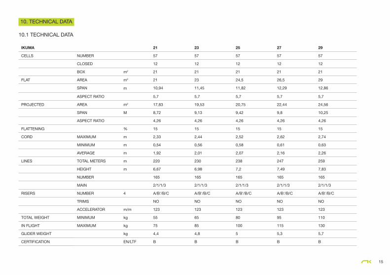
IKUMA 21 23 25 27 29
CELLS NUMBER 57 57 57 57 57
CLOSED 12 12 12 12 12
BOX m2 21 21 21 21 21
FLAT AREA m2 21 23 24,5 26,5 29
SPAN m 10,94 11,45 11,82 12,29 12,86
ASPECT RATIO 5,7 5,7 5,7 5,7 5,7
PROJECTED AREA m2 17,83 19,53 20,75 22,44 24,56
SPAN M 8,72 9,13 9,42 9,8 10,25
ASPECT RATIO 4,26 4,26 4,26 4,26 4,26
FLATTENING % 15 15 15 15 15
CORD MAXIMUM m 2,33 2,44 2,52 2,62 2,74
MINIMUM m 0,54 0,56 0,58 0,61 0,63
AVERAGE m 1,92 2,01 2,07 2,16 2,26
LINES TOTAL METERS m 220 230 238 247 259
HEIGHT m 6,67 6,98 7,2 7,49 7,83
NUMBER 165 165 165 165 165
MAIN 2/1/1/3 2/1/1/3 2/1/1/3 2/1/1/3 2/1/1/3
RISERS NUMBER 4 A/B'/B/C A/B'/B/C A/B'/B/C A/B'/B/C A/B'/B/C
TRIMS NO NO NO NO NO
ACCELERATOR m/m 123 123 123 123 123
TOTAL WEIGHT MINIMUM kg 55 65 80 95 110
IN FLIGHT MAXIMUM kg 75 85 100 115 130
GLIDER WEIGHT kg 4,4 4,8 5 5,3 5,7
CERTIFICATION EN/LTF B B B B B
15
10. TECHNICAL DATA
10.1 TECHNICAL DATA

16
10.2 MATERIALS DESCRIPTION
CANOPY FABRIC CODE SUPPLIER
UPPER SURFACE 9017 E25 PORCHER IND (FRANCE)
BOTTOM SURFACE N20DMF DOMINICO TEX CO (KOREA)
RIBS 9017 E29 PORCHER IND (FRANCE)
DIAGONALS 9017 E29 PORCHER IND (FRANCE)
LOOPS LKI - 10 KOLON IND. (KOREA)
REINFORCEMENT LOOPS W-420 D-P (GERMANY)
TRAILING EDGE REIFORCEMENT MYLAR D-P (GERMANY)
REINFORCEMENT RIBS LTN-0.8 STICK SPORTWARE CO. (CHINA)
THREAD SERAFIL 60 AMAN (GERMANY)
SUSPENSION LINES FABRIC CODE SUPPLIER
UPPER CASCADES DC - 040 LIROS GMHB (GERMANY)
UPPER CASCADES DC - 060 LIROS GMHB (GERMANY)
UPPER CASCADES DC - 100 LIROS GMHB (GERMANY)
UPPER CASCADES A-8000/U 50 EDELRID (GERMANY)
MIDDLE CASCADES TNL - 080 TEIJIM LIMITED (JAPAN)
MIDDLE CASCADES DC - 060 LIROS GMHB (GERMANY)
MIDDLE CASCADES A-8000/U 50 EDELRID (GERMANY)
MIDDLE CASCADES A-8000/U 130 EDELRID (GERMANY)
MIDDLE CASCADES A-8000/U 190 EDELRID (GERMANY)
MAIN A-8000/U 70 EDELRID (GERMANY)
MAIN A-8000/U 230 EDELRID (GERMANY)
MAIN A-8000/U 360 EDELRID (GERMANY)
MAIN BREAK TNL - 280 TEIJIM LIMITED (JAPAN)
THREAD SERAFIL 60 AMAN (GERMANY)
RISERS FABRIC CODE SUPPLIER
MATERIAL 3455 COUSIN (FRANCE)
COLOR INDICATOR PAD TECNI SANGLES (FRANCE)
THREAD N/F-66 YOUNG CHANG T&C LTD
MAILLONS 3.5 ANSUNG PRECISION (KOREA)
PULLEYS ID018041 RONSTAN (AUSTRALIA)
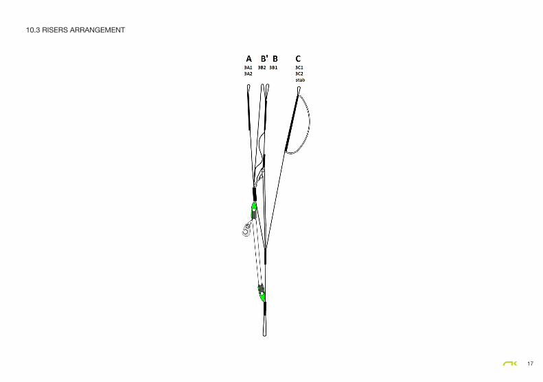
10.3 RISERS ARRANGEMENT
17

10.4 LINE PLAN
18
a1a2a3a4
a5a6
a7
a8
a9
a10
a11
b1b2b3b4b5
b6b7
b8b9
b10
b11c1c2c3c4c5
c6
c7c8c9
c10c11
d1d2d3d4
br1br2br3br4
d5d6
br5br6br7
br8br9br10
2A12A2
3A1
2B12B23B1
2C12C2
3C1
2D12D
2
2A32A4
2B32B4
2C3
3A2
3B2
3C2
2C4
2D3
2A5
stab
2BR12BR2
3BR14BR1
2BR33BR2
2BR4
2BR5
brmain
1234567891011121314151617
1819
2021
2223
2425
26
27
28
stab 2
19
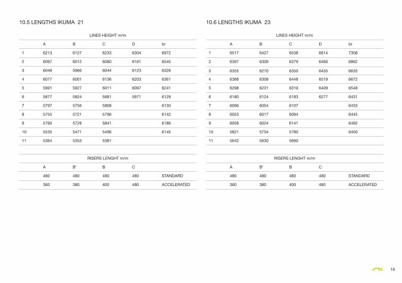
10.5 LENGTHS IKUMA 21 10.6 LENGTHS IKUMA 23
LINES HEIGHT m/m
A B C D br
1 6213 6127 6233 6304 6972
2 6097 6012 6080 6161 6545
3 6048 5966 6044 6123 6326
4 6077 6001 6136 6203 6361
5 5991 5927 6011 6097 6241
6 5877 5824 5881 5971 6129
7 5797 5756 5808 6130
8 5755 5721 5796 6142
9 5760 5728 5841 6186
10 5535 5471 5496 6145
11 5364 5353 5381
RISERS LENGHT m/m
A B' B C
480 480 480 480 STANDARD
360 380 400 480 ACCELERATED
LINES HEIGHT m/m
A B C D br
1 6517 6427 6538 6614 7308
2 6397 6309 6379 6466 6862
3 6355 6270 6350 6435 6635
4 6388 6308 6448 6519 6672
5 6298 6231 6319 6409 6548
6 6180 6124 6183 6277 6431
7 6096 6054 6107 6433
8 6053 6017 6094 6445
9 6058 6024 6141 6492
10 5821 5754 5780 6450
11 5642 5630 5660
RISERS LENGHT m/m
A B' B C
480 480 480 480 STANDARD
360 380 400 480 ACCELERATED

20
10.7 LENGTHS IKUMA 25 10.8 LENGTHS IKUMA 27
LINES HEIGHT m/m
A B C D br
1 6750 6657 6771 6856 7558
2 6627 6536 6608 6704 7098
3 6577 6490 6571 6665 6865
4 6612 6529 6673 6753 6904
5 6520 6451 6541 6640 6776
6 6398 6341 6401 6503 6656
7 6312 6268 6323 6658
8 6267 6230 6310 6671
9 6273 6238 6358 6720
10 6013 5943 5970 6678
11 5827 5815 5846
RISERS LENGHT m/m
A B' B C
480 480 480 480 STANDARD
360 380 400 480 ACCELERATED
LINES HEIGHT m/m
A B C D br
1 7039 6943 7062 7146 7880
2 6913 6819 6893 6989 7403
3 6863 6772 6856 6950 7161
4 6900 6815 6962 7042 7202
5 6805 6733 6827 6924 7070
6 6679 6619 6681 6782 6946
7 6590 6544 6600 6948
8 6544 6505 6587 6962
9 6550 6513 6637 7013
10 6279 6206 6249 6971
11 6085 6073 6120
RISERS LENGHT m/m
A B' B C
480 480 480 480 STANDARD
360 380 400 480 ACCELERATED

21
10.9 LENGTHS IKUMA 29
LINES HEIGHT m/m
A B C D br
1 7386 7286 7409 7500 8266
2 7256 7157 7235 7337 7767
3 7205 7110 7197 7297 7515
4 7245 7156 7310 7395 7559
5 7147 7072 7169 7272 7422
6 7015 6953 7017 7123 7293
7 6923 6875 6933 7296
8 6875 6834 6919 7310
9 6881 6843 6972 7365
10 6612 6536 6566 7323
11 6410 6397 6431
RISERS LENGHT m/m
A B' B C
480 480 480 480 STANDARD
360 380 400 480 ACCELERATED
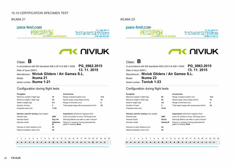
IKUMA 21 IKUMA 23
Class: BIn accordance with EN standards 926-2:2013 & 926-1:2006: PG_0963.2015Date of issue (DMY): 13. 11. 2015Manufacturer: Niviuk Gliders / Air Games S.L. Model: Ikuma 23Serial number: Toniuk 1-23
Configuration during flight testsParaglider AccessoriesMaximum weight in flight (kg) 85 Range of speed system (cm) 12.2Minimum weight in flight (kg) 65 Speed range using brakes (km/h) 14Glider's weight (kg) 4.6 Range of trimmers (cm) 0Number of risers 3 Total speed range with accessories (km/h) 25Projected area (m2) 19.53
Harness used for testing (max weight) Inspections (whichever happens first)Harness type ABS every 24 months or every 100 flying hoursHarness brand Niviuk Warning! Before use refer to user's manualHarness model Hamak M Person or company having presented the
glider for testing: NoneHarness to risers distance (cm) 44Distance between risers (cm) 44
1
A
2
A
3
A
4
A
5
A
6
A
7
A
8
A
9
A
10
B
11
A
12
A
13
A
14
B
15
A
16
A
17
A
18
A
19
A
20
A
21
A
22
A
23
0
24
�
Class: BIn accordance with EN standards 926-2:2013 & 926-1:2006: PG_0962.2015Date of issue (DMY): 13. 11. 2015Manufacturer: Niviuk Gliders / Air Games S.L. Model: Ikuma 21Serial number: Ikuma 1-21
Configuration during flight testsParaglider AccessoriesMaximum weight in flight (kg) 75 Range of speed system (cm) 12.2Minimum weight in flight (kg) 55 Speed range using brakes (km/h) 14Glider's weight (kg) 4.4 Range of trimmers (cm) 0Number of risers 3 Total speed range with accessories (km/h) 25Projected area (m2) 17.83
Harness used for testing (max weight) Inspections (whichever happens first)Harness type ABS every 24 months or every 100 flying hoursHarness brand Sup' Air Warning! Before use refer to user's manualHarness model Altiplume
MPerson or company having presented theglider for testing: None
Harness to risers distance (cm) 43Distance between risers (cm) 40
1
A
2
A
3
A
4
A
5
A
6
A
7
A
8
A
9
A
10
B
11
A
12
A
13
A
14
B
15
A
16
A
17
A
18
A
19
A
20
B
21
A
22
A
23
0
24
�
22
10.10 CERTIFICATION SPECIMEN TEST

IKUMA 25 IKUMA 27
Class: BIn accordance with EN standards 926-2:2013 & 926-1:2006: PG_0960.2015Date of issue (DMY): 13. 11. 2015Manufacturer: Niviuk Gliders / Air Games S.L. Model: Ikuma 25Serial number: Toniuk 6-25
Configuration during flight testsParaglider AccessoriesMaximum weight in flight (kg) 100 Range of speed system (cm) 12.5Minimum weight in flight (kg) 80 Speed range using brakes (km/h) 14Glider's weight (kg) 4.8 Range of trimmers (cm) 0Number of risers 3 Total speed range with accessories (km/h) 25Projected area (m2) 20.75
Harness used for testing (max weight) Inspections (whichever happens first)Harness type ABS every 24 months or every 100 flying hoursHarness brand Niviuk Warning! Before use refer to user's manualHarness model Hamak L Person or company having presented the
glider for testing: Olivier NefHarness to risers distance (cm) 42Distance between risers (cm) 44
1
B
2
A
3
A
4
A
5
A
6
A
7
A
8
A
9
A
10
B
11
A
12
A
13
B
14
B
15
A
16
A
17
A
18
A
19
A
20
A
21
A
22
A
23
0
24
�
Class: BIn accordance with EN standards 926-2:2013 & 926-1:2006: PG_0964.2015Date of issue (DMY): 13. 11. 2015Manufacturer: Niviuk Gliders / Air Games S.L. Model: Ikuma 27Serial number: Toniuk 1-27
Configuration during flight testsParaglider AccessoriesMaximum weight in flight (kg) 115 Range of speed system (cm) 12.5Minimum weight in flight (kg) 95 Speed range using brakes (km/h) 14Glider's weight (kg) 5.2 Range of trimmers (cm) 0Number of risers 3 Total speed range with accessories (km/h) 25Projected area (m2) 22.44
Harness used for testing (max weight) Inspections (whichever happens first)Harness type ABS every 24 months or every 100 flying hoursHarness brand Niviuk Warning! Before use refer to user's manualHarness model Hamak L Person or company having presented the
glider for testing: NoneHarness to risers distance (cm) 43Distance between risers (cm) 46
1
B
2
A
3
A
4
A
5
A
6
A
7
A
8
A
9
A
10
B
11
A
12
A
13
B
14
B
15
A
16
A
17
A
18
A
19
A
20
A
21
A
22
A
23
0
24
�
23
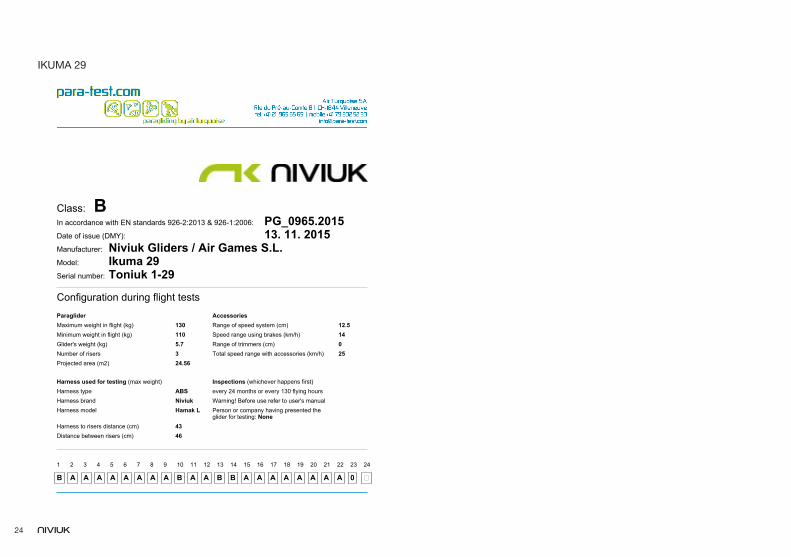
IKUMA 29
Class: BIn accordance with EN standards 926-2:2013 & 926-1:2006: PG_0965.2015Date of issue (DMY): 13. 11. 2015Manufacturer: Niviuk Gliders / Air Games S.L. Model: Ikuma 29Serial number: Toniuk 1-29
Configuration during flight testsParaglider AccessoriesMaximum weight in flight (kg) 130 Range of speed system (cm) 12.5Minimum weight in flight (kg) 110 Speed range using brakes (km/h) 14Glider's weight (kg) 5.7 Range of trimmers (cm) 0Number of risers 3 Total speed range with accessories (km/h) 25Projected area (m2) 24.56
Harness used for testing (max weight) Inspections (whichever happens first)Harness type ABS every 24 months or every 130 flying hoursHarness brand Niviuk Warning! Before use refer to user's manualHarness model Hamak L Person or company having presented the
glider for testing: NoneHarness to risers distance (cm) 43Distance between risers (cm) 46
1
B
2
A
3
A
4
A
5
A
6
A
7
A
8
A
9
A
10
B
11
A
12
A
13
B
14
B
15
A
16
A
17
A
18
A
19
A
20
A
21
A
22
A
23
0
24
�
23 24

The importance of small detailsniviuk.com