user’s manual - phanteks · user’s manual. 3 introduction ... front i/o 2x usb 3.0, mic,...
TRANSCRIPT

USER’S MANUAL


3
INTRODUCTION
Congratulations on your purchase of the Phanteks Enthoo Series Case and welcome to the User’s Guide. Phanteks believes that meaningful designs are created through the fusion of form and function.
Caution Please take a moment to carefully go through the installation guide. Phanteks will not take responsibility for any damages incurred due to incorrect installation and incorrect usage of this product. Thank you.
ENTHOO EVOLV ITX
Big on features and small in size, the Enthoo EVOLV ITX is a budget oriented chassis that uses a metal exterior. The case introduces a new unique bracket solution for mounting a radiator on top and a multifunctional bracket for reservoir, pump, and SSD/HDD.

4
TABLE OF CONTENTS
1. SPECIFICATIONS ................................................................................................................................................................................................................. 5
2. EXPLODED VIEW ................................................................................................................................................................................................................ 6
3. ACCESSORIES & BRACKETS ............................................................................................................................................................................................. 8
4. I/O PORTS ............................................................................................................................................................................................................................. 9
5. CONNECTIONS ................................................................................................................................................................................................................... 10
6. PANEL REMOVAL ................................................................................................................................................................................................................ 11
7. MOTHERBOARD INSTALLATION ................................................................................................................................................................................... 13
8. POWER SUPPLY INSTALLATION .................................................................................................................................................................................... 14
9. FILTERS REMOVAL ............................................................................................................................................................................................................. 15
10. FANS COMPATIBILITY ....................................................................................................................................................................................................... 16
11. RADIATOR BRACKET INSTALLATION ........................................................................................................................................................................... 17
12. HARD DRIVE CAGE ............................................................................................................................................................................................................ 19
13. DROP-N-LOCK SSD BRACKET ........................................................................................................................................................................................ 20
14. MULTIFUNCTIONAL MID PLATE ................................................................................................................................................................................... 21
15. WATERCOOLING INSTALLATION .................................................................................................................................................................................... 22
16. UPGRADE OPTIONS ........................................................................................................................................................................................................... 24
17. SERVICES AND SUPPORT ................................................................................................................................................................................................ 25

5
1. SPECIFICATIONS
PH-F200SP (included) Speed (rpm) 850 ±250 rpm Max Airflow 110.1 CFM Static Pressure 1.04mm H2O Acoustical Noise 25dB
CLEARANCE Graphic card 330 mm (13 in) CPU cooler 200 mm (7.9 in) Cable Management 28 mm (1.1 in) Motherboard - Radiator 120 mm form factor: 74 mm (2.9 in) 140 mm form factor: 54 (2.1 in) Warranty 5 Years
CASE SPECIFICATIONS Dimension 230 mm x 375 mm x 395 mm (W x H x D) Form Factor Mini ITX Tower Material(s) Steel Plates, Plastics, Steel chassis Motherboard support Mini ITX Weight Front I/O 2x USB 3.0, Mic, Headphone, Reset Side window Yes
EXPANSION & DRIVE BAYS Expansion slots 2
Internal 3.5” 2 (1x extra upgrade slot) Internal 2.5” 1 (1x extra upgrade slot)
COOLING 120 mm 140 mm 200mm Front 2x 2x 1x (included)
Top 2x 2x - Rear 1x 1x -
LIQUID COOLING 120 mm radiator 140 mm radiator Front Up to 240 Top Up to 240 Up to 280 Rear 120 140

6
2. EXPLODED VIEW
1
23
4
5
6
98
7
10
1112
13
14
1. Chassis2. Top Panel3. Power Button4. SSD Bracket5. I/O Port panel6. Right Side Panel7. Front Panel8. HDD Tray9. Hard Drive Cage10. Front Mesh cover11. Window Left Side Panel12. Multifunctional mid-plate13. Rear Dust Filters14. Radiator Bracket

7
1. Châssis2. Filtres de poussière inférieurs3. Bouton d’alimentation4. Support SSD5. Panneau du port E/S6. Panneau latéral droit7. Panneau frontal8. Bacs HDD9. Enclos du disque dur10. Couvercle de grille du panneau frontal11. Panneau latéral gauche12. Plaque centrale multifonctions13. Panneau supérieur14. Support de radiateur
1. Telaio 2. Filtri antipolvere inferiori 3. Tasto d’alimentazione4. Staffa SSD 5. Pannello porta I/O6. Pannello laterale destro7. Pannello frontale8. Vassoi per disco rigido9. Cage disco rigido 10. Copertura di rete frontale 11. Pannello laterale sinistro 12. Piastra centrale multifunzione13. Pannello superiore 14. Staffa radiatore
1. Chassi2. Painel Superior3. Botão de Alimentação4. Suporte do SSD5. Painel da Porta I/O6. Painel Lateral Direito7. Painel frontal8. Tabuleiros de HDD9. Berço do Disco Rígido10. Tampa de malha frontal 11. Painel Lateral Esquerdo12. Placa média multifuncional13. Filtros de Pó Inferiores 14. Suporte do Radiador
1. Chasis2. Panel superior3. Tasto d’alimentazione4. Soporte de unidad de estado sólido5. Panel de puerto de E/S6. Panel lateral derecho7. Panel frontal8. Bandejas de unidad de disco duro9. Compartimento de disco duro 10. Cubierta de malla frontal 11. Panel lateral izquierdo12. Placa central multifuncional13. Filtros de polvo inferiores 14. Soporte del radiador
1. Gehäuse2. Untere Staubfilter 3. Ein-/Austaste4. SSD-Halterung 5. E/A-Anschlussblende6. Rechte Seitenblende 7. Frontblende8. Festplatteneinsätze9. Festplattenkäfig 10. Vordere Gitterabdeckung 11. Linke Seitenblende12. Multifunktionale Platte in der Mitte13. Untere Staubfilter 14. Kühlkörperhalterung
1. Behuizing2. Toppaneel3. Power knop4. SSD beugel 5. I/O paneel6. Rechter zijpaneel7. Voorpaneel8. Harde schijf houder9. Harde schijf kooi10. Voorzijde mesh deksel11. Linker zijpaneel12. Multifunctional mid-plate13. Bodem stoffilter 14. Radiator beugel

8
SSD Bracket Support SSDSSD-HalterungStaffa SSDSuporte do SSDSoporte de unidad de estado sólidoSSD beugel
Multifunctional mid-platePlaque centrale multifonctionsPiastra centrale multifunzionePlaca média multifuncionalPlaca central multifuncionalMultifunktionale Platte in der MitteMultifunctional mid-plate
3. ACCESSORIES & BRACKETS
ITEM DESCRIPTION USE QTY
Screw M3 x 5mm Motherboard/ODD/SSD 13
Screw 6-32 x 6mm PSU, Brackets 5
Thumb Screws 6-32 x 6mm
PSU, Brackets, HDD cages 2
ITEM DESCRIPTION USE QTY
150mm Zip Tie 4
Lock HDD tray
(1x)
Motherboard / SSD
9
ITEM DESCRIPTION USE QTY
Screw M3 x 5mm Motherboard/ODD/SSD 13
Screw 6-32 x 6mm PSU, Brackets 5
Thumb Screws 6-32 x 6mm
PSU, Brackets, HDD cages 2
ITEM DESCRIPTION USE QTY
150mm Zip Tie 4
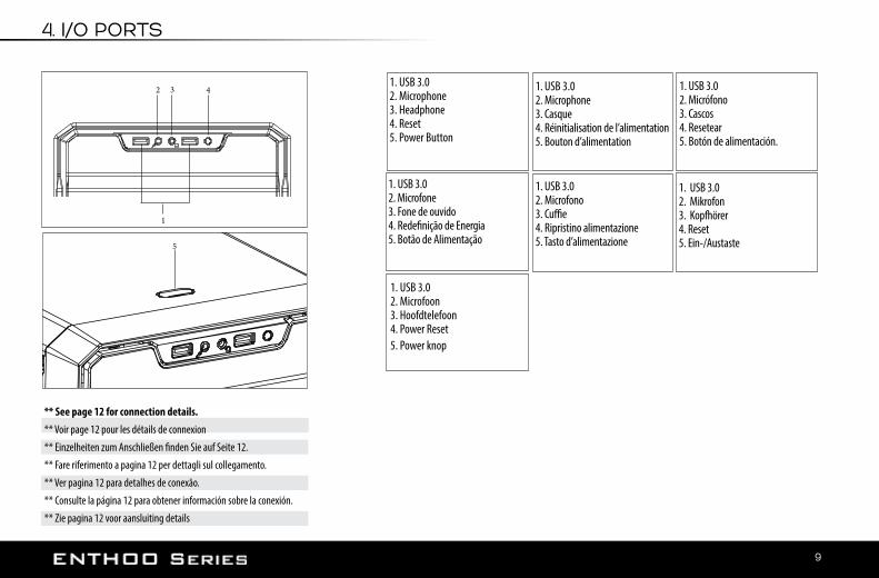
4. I/O PORTS
** See page 12 for connection details.** Voir page 12 pour les détails de connexion
** Einzelheiten zum Anschließen finden Sie auf Seite 12.
** Fare riferimento a pagina 12 per dettagli sul collegamento.
** Ver pagina 12 para detalhes de conexão.
** Consulte la página 12 para obtener información sobre la conexión.
** Zie pagina 12 voor aansluiting details
1
32 4
5
1. USB 3.02. Mikrofon3. Kopfhörer4. Reset5. Ein-/Austaste
1. USB 3.02. Microfone3. Fone de ouvido4. Redefinição de Energia5. Botão de Alimentação
1. USB 3.02. Microphone3. Casque4. Réinitialisation de l’alimentation5. Bouton d’alimentation
1. USB 3.02. Microfono3. Cuffie4. Ripristino alimentazione5. Tasto d’alimentazione
1. USB 3.02. Microfoon3. Hoofdtelefoon4. Power Reset5. Power knop
1. USB 3.02. Micrófono3. Cascos4. Resetear5. Botón de alimentación.
1. USB 3.02. Microphone3. Headphone4. Reset5. Power Button
10
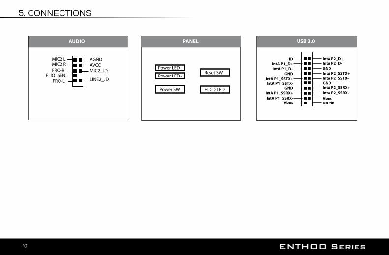
IntA P2_D+IntA P2_D-GNDIntA P2_SSTX+IntA P2_SSTX-GNDIntA P2_SSRX+IntA P2_SSRX-VbusNo Pin
IDIntA P1_D+IntA P1_D-
GNDIntA P1_SSTX+IntA P1_SSTX-
GNDIntA P1_SSRX+IntA P1_SSRX-
Vbus
USB 3.0
5. CONNECTIONS
AUDIO
AGND AVCCMIC2_JD
LINE2_JD
MIC2 LMIC2 RFRO-R
F_IO_SENFRO-L
PANEL
Power SW
Power LED +Reset SW
H.D.D LED
Power LED -

11
6. PANEL REMOVAL
Unscrew the 4 thumb screws to remove the side panels.Dévissez les vis à main pour enlever les panneaux latéraux.Lösen Sie die 4 Rändelschrauben zum Entfernen der seitlichen Blenden.Svitare le 4 viti per rimuovere i pannelli laterali.Desaperte os 4 parafusos para remover os painéis laterais.Desatornille los 4 tornillos de pulgar para retirar los paneles laterales.Schroef 4 duimschroeven los om de zijpanelen te verwijderen.

12
6. PANEL REMOVAL
For the front panel, place your hands on the area shown and pull outward.Pour le panneau avant, placez vos mains sur la zone affichée, et tirez vers l’extérieur. Positionieren Sie auch bei der Frontblende Ihre Hände an der angezeigten Stelle und ziehen Sie sie dann nach außen. Per il pannello anteriore, posizionare le mani sull’area mostrata e tirare verso l’esterno. Para o painel frontal, coloque as mãos na área ilustrada e puxe para fora. Para sacar el panel frontal, coloque las manos en el área indicada y tire hacia afuera. Voor het verwijderen van het voorpaneel, trek het paneel naar u toe zoals aangegeven op de tekening.

13
7. MOTHERBOARD INSTALLATION
Install the motherboard with the provided M3 screws.Installez la carte mère avec les vis M3 fourniesInstallieren Sie das Motherboard mit den mitgelieferten M3-Schrauben.installare la scheda madre con le viti M3 fornite in dotazione.Instale a placa mãe com os parafusos M3 fornecidos.instale la placa base con los tornillos M3 que se suministran.Installeer het moederbord met de meegeleverde M3- scrhoeven
Standoff screws are pre-installed. Les vis du support sont préinstallées. Abstandhalterschrauben sind vorinstalliert. Le viti dei distanziatori sono installate precedentemente.Os parafusos separadores estão pré-instalados. Los tornillos separadores vienen preinstalados. Afstandschroeven zijn vooraf geïnstalleerd

14
8. POWER SUPPLY INSTALLATION
(4x)
REAR VIEW
Use the provided screws to secure the PSU in place. Utilisez les vis fournies pour fixer le bloc d’alimentation en place.Befestigen Sie das Netzteil mit den mitgelieferten Schrauben.Utilizzare le viti fornite per fissare la PSU in sito.Use os parafusos para fixar a Unidade de Proteção e de Comutação.Utilice los tornillos suministrados para fijar la fuente de alimentación en su posición.Gebruik de meegeleverde schroeven om de voeding vast te zetten.

15
9. FILTERS REMOVAL
To remove the rear filter, push down and pull out. Remove the front filters by first taking out the front panel then pull the filter out. Pour retirer le filtre arrière, appuyez dessus et sortez-le. Retirez les filtres avant en sortant d’abord le panneau avant, puis en tirant sur le filtre.
Der hintere Filter wird durch Herunterdrücken und Herausziehen entfernt. Entfernen Sie die vorderenFilter, indem Sie zuerst die Vorderseite abnehmen und dann den Filter herausziehen.
Per rimuovere il filtro posteriore, premere ed estrarre. Rimuovere i filtri anteriori estraendo prima il pannello anteriore e quindi estraendo il filtro.
Para remover o filtro traseiro, empurre para baixo e puxe para fora. Retire os filtros frontais primeiramente removendo o painel frontal, em seguida, puxe o filtro para fora.
Para extraer el filtro trasero, presione y tire hacia fuera. Retire los filtros delanteros extrayendo primero el panel delantero y, a continuación, tire del filtro hacia fuera.
Om de achter filter te verwijderen dient de gebruiker eerst bij de hendel omlaag te drukken, vervolgens achterwaarts uit te trekken. Om de voor filter te verwijderen dient de voorpaneel eerst verwijderd te worden, zodat de filter eruit getrokken kan worden.
To clean the dust filters, run slow moving water through the filters. Dry filters before reinstalling.Pour nettoyer les filtres à poussière, faites couler de l’eau sur les filtres. Séchez les filtres avant de réinstaller.
Reinigen Sie die Staubfilter, indem Sie sie unter langsam fließendem Wasser abspülen. Filter vor Wiedereinbau trocknen.
Per pulire i filtri antipolvere, far correre lentamente l’acqua attraverso i filtri. Asciugare i filtri prima di installarli di nuovo.
Para limpar os filtros de poeiras, passe água em movimento lento através dos filtros. Seque os filtros antes de reinstalar.
Para limpiar los filtros de polvo, deje que caiga agua corriente lentamente sobre los filtros. Seque los filtros antes de volverlos a colocar.
Laat langzaam stromend water door de filter lopen voor het reinigen van de filters. Droog de filters voordat u het weer bevestigd.

16
10. FAN COMPATIBILITY
FAN COMPATIBILITY TABLE200mm 140mm 120mm
Top 2 2
Front 1(1x included)
2 2
Rear 1 1

17
11. RADIATOR BRACKET INSTALLATION
Locate the 4 screws (silver colored screws) and remove.Pour le retrait, dévissez les 4 vis argentées et sortez le support.
Zur Deinstallation lösen Sie die 4 silbernen Schrauben und ziehen Sie die Halterung heraus.
Per rimuovere, svitare le 4 viti argentate ed estrarre la staffa.
Para remover desaperte os 4 parafusos de prata e puxe o suporte para fora.
Para extraerlo, desatornille los 4 tornillos plateados y tire del soporte hacia fuera.
Voor het uithalen van de radiator beugel dient de 4 zilver gekleurde schroeven verwijderd te worden (zie afbeelding voor schroef posities)

18
BRACKET COMPATIBILITY TABLE
Radiator Fansup to 240mmup to 280mm
up to (2x) 120mmup to (2x) 140mm
*For easy radiator and fans installation, please check compatibility table.*Pour une installation facile du radiateur et des ventilateurs, consultez le tableau de compatibilité. *Unter Zuhilfenahme der Kompatibilitätstabelle lassen sich der Kühlkörper und die Lüfter probemlos installieren. *Per un’installazione di radiatore e ventole agevole, verificare la tabella di compatibilità.*Para facilitar a instalação do radiador e dos ventiladores, por favor, verifique a tabela de compatibilidade.*Para instalar fácilmente el radiador y los ventiladores, consulte la tabla de compatibilidad.*Voor de installatie van radiator en ventilatoren , raadpleeg de compatibiliteitstabel. To install, align the bracket and slide in. Use the 4x silver screw to lock in place.
Pour l’installation, alignez le support et glissez-le à l’intérieur. Utilisez les 4 vis argentées pour le verrouiller.
Zur Installation richten Sie die Halterung aus und schieben Sie sie hinein. Befestigen Sie sie mit 4 silbernen Schrauben.
Per installare, allineare la staffa e farla scorrere all’interno. Utilizzare le 4 viti argentate per bloccare in posizione.
Para instalar, alinhe o suporte e deslize. Use os 4x parafusos prateados para travar no lugar.
Para instalarlo, alinee el soporte y deslícelo en el interior. Utilice 4 tornillos plateados para fijarlo en su posición.
Installeer de radiator/ventilatoren op de beugel en schuif deze weer terug in de rail. Bevestig de radiator beugel met de 4 zilver gekleurde schroeven.
11. RADIATOR BRACKET INSTALLATION

19
3.5” INSTALLATION HDD BRACKET REMOVAL
2.5” INSTALLATION
12. HARD DRIVE CAGE
Place hard drive into tray and push in the arms to lock. Placez le disque dur dans le logement et poussez les bras pour le verrouiller.
Bringen Sie die Festplatten im Fach an und drücken die Arme zum Verriegeln hinein.
Collocare disco rigido nel cassetto e spingere i bracci verso l’interno per bloccare.
Coloque o disco rígido na bandeja e empurre os braços para travar.
Coloque el disco duro en la bandeja y pulse sobre los brazos para que quede sujeto.
Plaatst de harde schijf in de lade en duw de armen in voor vergrendeling.
Align the SSD onto the mounting holes and screw in.Aligner le SSD avec les trous de montage et vissez.
Richten Sie die SSD an den Montagelöchern aus und befestigen die Schrauben.
Allineare l’unità ssd su i fori di installazione e fissare le viti.
Alinhe o SSD nos orifícios de fixação e parafuse.
Alinee la unidad de estado sólido con los agujeros de montaje y atorníllela.
Lijn de SSD uit op de bevestigingsgaten en schroef de schroeven in.
Unscrew the 8x screws to remove the HDD Cage. Dévissez les 8 vis pour retirer la cage HDD.Lösen Sie 8 Schrauben, um den Festplattenkäfig zu entfernen.Svitare le 8 viti per rimuovere la gabbia dell’HDD.Solte os 8x parafusos para remover a Gaiola de HDD.Desatornille los 8 tornillos para quitar la carcasa de la unidad de disco duro.Om de HDD kooi te verwijderen, dient de 4 schroeven verwijderd te worden.
20
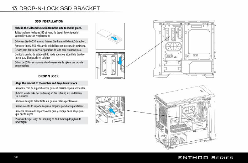
13. DROP-N-LOCK SSD BRACKET
SSD INSTALLATION
Slide in the SSD and screw in from the side to lock in place.
Align the bracket to the rubber and drop down to lock.Alignez le coin du support avec le guide et baissez-le pour verrouiller.
Richten Sie die Ecke der Halterung an der Führung aus und lassen sie einrasten.
Allineare l’angolo della staffa alla guida e calarla per bloccare.
Alinhe o canto do suporte ao guia e empurre para baixo para travar.
Alinee la esquina del soporte con la guía y empuje hacia abajo para que quede sujeta.
Plaats de beugel langs de uitlijning en druk richting de pijl om te bevestigen.
DROP N LOCK
Faites coulisser le disque SSD et vissez-le depuis le côté pour le verrouiller dans son emplacement.
Schieben Sie die SSD ein und fixieren Sie diese seitlich mit Schrauben.Far scorre l’unità SSD e fissare le viti dal lato per bloccarla in posizione.Deslize para dentro do SSD e parafuse do lado para travar no local.Deslice la unidad de estado sólido hacia adentro y atorníllela desde el lateral para bloquearla en su lugar.Schuif de SSD in en monteer de schroeven via de zijkant om deze te vergrendelen.

21
14. MULTIFUNCTIONAL MID PLATE
Drop-n-Lock mounting rubbers are pre-installed on the SSD mounting location. To use the HDD Bracket, unscrew the mounting rubbers and relocated the rubbers to the correct HDD mounting location (PH-HDBKT_01 required)Des pièces de montage en caoutchouc de type poser/verrouiller sont préinstallés à l’emplacement de montage de SSD. Pour utiliser le support de HDD, dévissez 4 pièces de montage en caoutchouch et replacez-les à l’emplacement de montage du HDD (PH-HDBKT_01 requis) Montagegummis mit Schnellverriegelung wurden im Voraus im SSD-Montagebereich installiert. Zur Verwendung der Festplattenhalterung schrauben Sie die 4 Montagegummis ab und bringen Sie sie im richtigen Festplattenmontagebereich wieder an (PH-HDBKT_01 erforderlich).Le gomme di appoggio Drop-n-Lock sono preinstallate nella posizione di montaggio SSD. Per utiliz-zare la staffa dell’HDD, svitare delle gomme di appoggio e riposizionare le gomme nella posizione di montaggio dell’HDD corretta (PH-HDBKT_01 necessario)Borrachas de fixação Drop-n-Lock são pré-instaladas no local de montagem do SSD. Para usar o suporte de HDD, solte 4 das borracha de montagem troque as borrachas para o local de montagem correta do HDD (PH-HDBKT_01 necessário)Las gomas de montaje con función “Colocar y bloquear” están preinstaladas en la ubicación de mon-taje de la unidad de estado sólido. Para utilizar el soporte de la unidad de disco duro, desatornille las gomas de montaje y vuelva a colocarlas en la ubicación de montaje correcta de la unidad de disco duro (se necesita PH-HDBKT_01)Drop-N-Lock bevestigingsrubbers zijn voor geïnstalleerd op de SSD bevestingspunten. Voor gebruik van een 3.5” HDD beugel moeten deze bevestigingsrubbers verplaatst worden naar de correcte posities zoals aangegeven op de midden plaat.
SSD Mounting locationEmplacement de montage du SSD
SSD-MontagebereichPosizione di montaggo SSDLocal de montagem do SSD
Ubicación de montaje de la unidad de estado sólidoSSD bevestigingspunten
HDD Mounting LocationEmplacement de montage du HDD
Festplattenmontagebereich Posizione di montaggio HDD Local de montagem do HDD
Ubicación de montaje de la unidad de disco duroHDD bevesitigingspunten
Pump Bracket Mounting LocationEmplacement de montage du crochet de la pompe
Montagebereich der Pumpenhalterung Posizione di montaggio della lanterna
Local de montagem do suporte da bombaUbicación de montaje del soporte de bomba
Pomp beugel bevestigingspunt
Reservoir Mounting LocationEmplacement de montage du réservoir
Montagebereich des Behälters Posizione di montaggio serbatoio
Local de montagem do reservatórioUbicación de montaje del depósito
Reservoir bevestigings punt

22
15. WATERCOOLING INSTALLATION
240mm, 280mm
120mm, 140mm
140mm 120mm
WATERCOOLING RADIATOR COMPATIBILITY
120mm
240mm
*Radiator Bracket required*Crochet de radiateur requis *Kühlkörperhalterung erforderlich*Staffa del radiatore necessaria*Suporte do radiador necessário*Se necesita el soporte de radiador*Radiator beugel vereist
Push-pull configuration
Push configuration
RADIATOR
RADIATOR
FAN
FAN
FAN
FAN
FAN
FAN

23
Radiator Size Taille de radiateurKühlkörpergröße
Dimensioni del radiatoreTamanho do radiadorTamaño del radiador
Radiator lengte
FrontAvant
VorderseiteParte frontale
FrenteFrontal
Voorkant
RearArrière
RückseiteParte posteriore
TraseiraPosterior
Achterkant
TopDessus
OberseiteParte superiore
TopoSuperior
Bovenkant
120mm 240mm
15. WATERCOOLING INSTALLATION
120 MM FORM FACTOR RADIATORS
Radiator Size Taille de radiateurKühlkörpergröße
Dimensioni del radiatoreTamanho do radiadorTamaño del radiador
Radiator lengte
FrontAvant
VorderseiteParte frontale
FrenteFrontal
Voorkant
RearArrière
RückseiteParte posteriore
TraseiraPosterior
Achterkant
TopDessus
OberseiteParte superiore
TopoSuperior
Bovenkant
140mm 280mm
*Caution: Supported Radiator size and thickness varies depending on your setup.*Avertissement : Les tailles de radiateur et les épaisseurs supportées varient en fonction de votre
configuration.
*Achtung: Unterstützte Kühlkörpergröße und -dicke variieren je nach Aufbau.
* Attenzione: Le dimensioni e lo spessore supportati per il radiatore dipendono dalla configurazione.
*Atenção: O tamanho e espessura do Suporte do Radiador variam dependendo da configuração.
*Precaución: el grosor y el tamaño del radiador compatibles varían según la instalación que realice.
*Let op : Ondersteunde radiator grootte en dikte varieert afhankelijk van de opstelling.
140 MM FORM FACTOR RADIATORS

24
16. UPGRADE OPTIONS
These additional upgrade accessories are not included in the case.Ces produits de mise à niveau supplémentaires ne sont pas comprises dans le boîtier.
Diese zusätzlichen Aufrüstprodukte sind im Gehäuse nicht enthalten.
Queste prodotti di aggiornamento aggiuntive non sono incluse nel case.
Estas produtos de atualização adicionais não estão incluídas no gabinete.
Estas productos de actualización adicionales no están incluidas en la caja.
De volgende uitbreidings accessoires zijn niet inbegrepen bij de kast.
PWM hub upgrade (PH-PWHUB_01) Pump bracket upgrade (PH-PUMBKT_01)
SSD / 3.5” HDD upgrade (PH-SDBKT_01 / PH-HDDKT_01)

25
17. SERVICES AND SUPPORT
If you have any questions or concerns, please visit Phanteks’ website for technical support. We consider customer support, satisfaction and feedback an essential element of our overall marketing effort. Please feel free to contact our support team. Thank you!
Contact Us at: www.phanteks.comwww.phanteksusa.comwww.phanteks.cn
For Warranty Information, please visit Phanteks’ website.