user's manual vw3a66301 - tecdriver pcmcia commcard vw3a66301.pdf · altivar 66 variables ......
TRANSCRIPT

C 66PCMCIA communication card
UNI-TELWAY, MODBUS/JBUSprotocols
VW3-A66301
Serial link via graphic keypad port
User's manual
TE

NOTEAlthough every care has been taken in the preparation of this document,
Schneider Electric SA cannot guarantee the contents and cannot be held responsible for any errors it maycontain or for any damage which may result from its use or application.
The hardware, software and services described in this document may be changed or modified atany time, either from a technical point of view or in the way they are operated. Their description can in noway be considered contractual.

1
ContentsHardware setup
Introduction 2
Installing the card 3 and 4
Connection to multidrop bus 5 to 7
Software setup
Configuration of the communication functions 8 to 10
Communication state 11
Diagnostics 12
Description of protocols
UNI-TELWAY requests 13 to 16
MODBUS / JBUS protocol 17 to 28
Graphic keypad serial link 29 to 33
Communication principle 34 to 43
Altivar 66 variables
Command and adjustment variables 44 to 47
Signalling variables 48 to 60
Configuration variables 61 to 93
Address zone common to Altivar 66 and Altivar 45.2 94 to 98
Index 99 to 111
COMMANDS
CONFIGURATION
SIGNALLING

2
Introduction
The communication card reference VW3-A66301 is designed for use with Altivar 66 speedcontrollers fitted with VW3-A66205, VW3-A66201Q or VW3-A66202Q communication interfaces.
It is designed to integrate these power switching components into modern control systemarchitectures by enabling them to be connected to a multidrop industrial bus.
Data exchanges enable all functions of the Altivar 66 to be used :
• function configuration,• remote downloading of settings,• control and supervision,• monitoring,• diagnostics.
The VW3-A66301 communication card, in extended type 3 PCMCIA format, has a 3 mconnection cable fitted with a 15-pin SUB-D connector.
This card manages the following communication protocols :
• UNI-TELWAY,• MODBUS, RTU / JBUS,• MODBUS ASCII.
Note : PCMCIA : Personal Computer Memory Card International Association
For optimum use of this manual, we recommend that you read the section entitled"Communication principle". In addition, use the index at the end of this manual to helpyou find Altivar 66 parameters.
Hardware setup

3
Installing the card
• Receipt :Ensure that the card reference printed on the label is the same as that on the delivery notecorresponding to the delivery advice.Remove the packaging and check that the communication option card has not been damagedin transit.
• Installing the card in the speed controller :Before starting work on the controller, disconnect the power supply and wait for the capacitorsto discharge (around 1 minute after switching off).
• Mounting precautions :To access the slot for mounting the extension card, unlock the protective cover and pivot it fromright to left.Check that there is no voltage on the DC bus : red LED off.Remove the IP20 protective cover from the J10 connector on the control card.Mount the option card on the control card by plugging it into the J10 terminalblock, press on both sides of the J10 connector with your fingers to plug it in securely, and fixit using the two captive screws.
Hardware setup
The example oppositeis a VW3-A66205 card
Before mounting,remove the coverfrom the J10connector on thecontrol card
Captive screws
Red LED indicating presence ofvoltage on DC bus

4
Hardware setup
Installing the card
Once the communication interface (VW3-A66205, VW3-A66201Q or VW3-A66202Q) has beenmounted in the speed controller :
• Insert the VW3-A66301 communication card into its slot so that the 3-meter connection cable is pointing to the left outside the speed controller.
Note : For ratings of ATV66-U41N4 to D12N4 / ATV66-U41M2 to U90M2 break off the precut(1) tab.
1
5
Connection to multidrop bus
SUB-D connector pin configuration
The transmission interface is electrically isolated from the speed controller in accordance with theRS 485 and RS 422 (RS 232 C compatible) standards. It is available on a 15-pin SUB-D connector.
Connection to standard RS 485 bus
Pins to be used
Recommendations
• use a shielded cable with 2 pairs of twisted conductors,• connect the reference potentials to each other,• maximum length of line : 1000 meters,• maximum length of drop cable : 20 meters,• do not connect more than 28 stations to one bus,• cable routing : keep the bus away from the power cables
(at least 30 cm) with any crossovers at right angles, and connectthe cable shielding to the ground of each device,
• fit a line terminator at both ends of the line.
Hardware setup
1
2
3
4
5
6
7
815
14
13
12
11
10
9
Side view of externalcontacts
1 nF
120Ω
7
14
150V
D(B)
D(A)
Zt line terminator recommendedat both ends of the line
transmis-sion
enable
8
23
14
7
515
RD (B)
RD (A)
D (B)
D (A)E
5V
5V
4,7 kΩ
4,7 kΩ
100 kΩ
100 kΩ
OV
0V
0V0V
&
&RX
TX

6
Connection to multidrop bus
Various accessories are available to facilitate connection of equipment.
– Cables for TSX-CSA… bus sold in lengths of 100, 200 or 500 m.
– TSX-SCA62 subscriber connector
This passive unit consists of a printed circuit fitted with screw terminal blocks and enables twodevices to be connected to the bus. It includes an end of line terminator when the connector isat the end. The switches in the socket must be positioned in the following manner :
switch number switch position
2 OFF
3 OFF
5 OFFthe position of the other switches has no effect.
Example of connection to UNI-TELWAY bus
Note : it is imperative that the earths are connected between the TSX-SCA unit and the Altivar 66to ensure the system operates correctly.In addition, these connections must be as short as possible.
Hardware setup
TSX-SCM 21.6 TSX-CSB015
TSX-CSAXXX
TSX-SCA62
VW3-A66205 orVW3-A66201QVW3-A66202QVW3-A66301
ALTIVAR-66 ALTIVAR-66 ALTIVAR-66

7
Connection to multidrop bus
Connection to standard RS 422 bus
Pins to be used
RS 232 C connection
Pins to be used
Hardware setup
3
2
7
14
8
5
15
T X
R X
SG common
3
7
14
8
150V
D(B)
D(A)
RD(B)
RD(A)
datatransmission
datareception

8
Software setup
Configuration of the communication functions
Initial power-up
To gain a good understanding of accessing the various menus we recommend that you consultthe speed controller programming manual.
A message appears on the screen on initial power-up which enables identification of the option.
The reference number of the chosen card and its versionappear after OPT.
Confirm acknowledgment of the option by pressingENT. This reconfigures the speed controller to its factorysettings.
In the drive identification menu, it is possible to check thereference number, the drive number and option 3 selectedusing the directional keys.
This screen appears on power-up if an option has beenremoved which was configured during a previous power-up.
Cut the general power supply to the speed controllerbefore reinstalling the extension card (see page 3).
TO RESET THE FAULT
YOU NEED TO REINSTALL
OPT.:VW3A66205
or initialize drive
to factory settings
ENT to initialize
ENT ESC
DRIVE IDENTIFICATION
ATV66U41N4 , DC ,V3.2
Power : 2.2kW/3HP
In= 5.8A,Imax= 8.0A
SUPPLY : 400-415 V
†,™
OPT.1 VW3A66205
ENT ESC
OPT. :VW3A66205
INSTALLED
REMEMBER YOU NEED TO
CONFIGURE THE OPTION
ENT to continue
FAULT
OPT. :VW3A66205
IS NOT RECOGNIZED
OR
HAS BEEN REMOVED
ENT to continue
9
Configuration of the communication functions
Configuration
After installing the option, select menu 11 "Communication" to access the card configuration.(To move around use the keys)To access menu 11, remember to unlock the access to menus.
This menu includes 5 parameters for configuringthe address, protocol, transmission speed,frame format and parity.
When a factory setting is made with the PCMCIA card present : menu 11 remains configured.
Protocol
(Modbus RTU = Jbus)
Address
The default address setting is to 0 (not configured) and the maximum is 31.
MAIN MENU
ENTACCESS LOCK
PARTIAL UNLOCKTOTAL UNLOCK
PARAMETER SETTINGI/O MAPFAULT HISTORYDISPLAY CONFIGURATIONKEYPAD CONFIGURATIONDRIVE CONFIGURATIONGENERAL CONFIGURATIONDIAGNOSTIC MODEDRIVE INITIALIZATIONACCESS LOCKCOMMUNICATIONCOMM. STATE
Software setup
---
UNI-TELWAY
Modbus RTU
Modbus ASC
FIPIO
MODBUS +
INTERBUS-S
a
11- COMMUNICATION
PROTOCOL : UTW
ADDRESS : 0
TRAN. SPEED : 9.6
FORMAT : 8.1 STOP
PARITY : ODD
ENT
a
b
c
d

1 0
Configuration of the communication functions
Transfer speed
• Transmission speed setting from 300bits/s to 19,200 bits/s.
Default setting of 9,600 bits/s.
Frame format
• Frame format. There are 4 formats 7 bits with 1 or 2 stop bits 8 bits with 1 or 2 stop bits.
Parity
Parity assignment.
The format is fixed for UNITELWAY (8 bits 1 stop ODD)For Modbus RTU : only the 8-bit format is available.
Only the following formats are permitted :
8 bits 1 stop all selections are possible.8 bits 2 stop only NO.7 bits NO cannot be selected.
Software setup
c
7b 1 stop
7b 2 stop
8b 1 stop
8b 2 stop
0.3
0.6
1.2
2.4
4.8
9.6
19.2
b
NO
ODD
EVEN
d

1 1
Software setup
Communication state
Menu 12 on the graphic keypad displays the communication state.
"Card missing" display
In this case, the communication card is missingor not yet configured.
"Communication card present" display
Note : the "UTW / Modbus" indication is uniqueand corresponds to the name of the option card.It is irrelevant whether the protocol isUNI-TELWAY or Modbus ."Not configured" indicates that the card hasbeen identified but the protocol has not beenconfigured."Configuration error" indicates that the identifiedcard does not correspond to the protocolconfigured.
Card display during operation
Different network states are possible with thecommunication card :initializing, bus active, bus inactive
12 COMM. STATE
Card Missing
See Menu 11
12 COMM. STATE
VW3A66301 V1.0
UTW/Modbus ADR. 0
Not configured
See Menu 11
12 COMM. STATE
VW3A66301 V1.0
UTW/Modbus ADR. 0
Bus active
CPT Message 00000

1 2
COM lamp ERR lamp Probable cause Corrective actiongreen red
1 0 Normal operation
1/2 0 Incorrect communication Check configuration.configuration, or communication Ensure software is compatible.fault with the Altivar 66
0 1 Bus communication fault Check position of the switches ofthe TSX-SCA 62 subscriberconnector of the Altivar 66 (whenoff).Check connections, presenceconfiguration and operationof link master.
0 0 PCMCIA card or speed controller Remove the PCMCIA card andfault check the Altivar 66. Replace the
Altivar 66 or the card as necessary.
Software setup
Diagnostics
Fault
For the communication fault codes refer to the user's manual for the PCMCIA communicationcard interface.
Additional diagnostics
Check the state of the 2 indicator lamps on the front panel of the VW3-A66301 communication card.
ERR
COM
Cable
Lamp status : 0 = off 1/2 = flashing 1 = on

1 3
Request Code (hex) Altivar 66
Identification H’0F’ YesProtocol version H’30' YesStatus H’31' YesMirror H’FA’ YesRead error counters H’A2' YesReset counters H’A4' Yes
Read a bit H’00' YesWrite a bit H’10' Yes
Read a word H’04' YesWrite a word H'14' Yes
Read objects H’36' 63 words max.Write objects H’37' 60 words max.
Event Yesdata – 2 words
Specific H’F2' See later
Description of protocols
UNI-TELWAY requests
List of requestsThe following table describes the requests accepted by the Altivar 66 and their limits.Details of the coding of the requests are given in the UNI-TELWAY reference manual.
Identification requestResponse code = H'3F'Product type = H'14' for AltivarSub-type = H'66' Altivar 66Product version = H'XX' software version (e.g. : H'21' for V2.1)ASCII string* = product reference (e.g. : VAR-66U29N4)
* The first byte of an ASCII string always corresponds to the length of the string.
Status requestResponse code = H'61'Current status = H'XX'(present at bit 0 : internal faulthigh state) bit 1 : correctable fault
bit 2 : uncorrectable faultbit 3 : not significantbit 4 : not significantbit 5 : not significantbit 6 : speed controller stopped (RDY or SLC or fault)bit 7 : speed controller in LOCAL control
Status mask = H'C7' indicates the significant bits for the current status

1 4
Description of protocols
UNI-TELWAY requests
Requests to read and write objectsThese requests are used to access several words within the limits described on the previous page.These requests can be coded by specifying :
Question code (TXTi,C) = H’36' (read) or H’37' (write)Category = 0...7Segment = H’68' (internal word)Object type = H’06' for a byte (8 bits) in read-only or H’07' for a word (16 bits)
in read and writeObject address = H’xxxx’Etc.Reserved or unused words are read as 0 and if written they have no meaning.The response to the "write objects" request is accepted if at least one word is written.
Example : programming on a TSX7 PLC using a text block. READ words W2020 to W3023 of the Altivar 66.
– Using word type object = H’07'Transmission text block Reception text blockTxTi,C = H’0736' (category + request) TxTi,V = H’66' (confirm)TxTi,L = 6 TxTi,S = 9 (9 bytes received)+ transmission table + reception table
H'07' H'68'
2020
4
W2020 (Lo) H'07'
W2021 (Lo) W2020 (Hi)
W2022 (Lo) W2021 (Hi)
W2023 (Lo) W2022 (Hi)
W2023 (Hi)
The data received in the reception table is offset by one byte. It is the application program whichmust correct the data (for example by successive offsets) before using it.
Internal word segmentWord type
4 words to read
Number of first word

1 5
W2019 (Hi) H'06'
W2020
W2021
W2022
W2023
Description of protocols
This programming enables words to be correctly positioned in the reception table.
Event dataThe Altivar 66 transmits data on its own initiative to the UNI-TELWAY link master without havingfirst received a question.
This data is sent via the "unsolicited data" request and does not require a response from thereceiver.
Data is transmitted in the following two cases :– When a fault appears or disappears (rising or falling edge at status register bit W2040,2).– When the speed controller is controlled locally via one of its logic inputs, if the input is assignedto this function (rising or falling edge at this input), or via the local key on the interface for thePCMCIA communication card.
Size of event data : 2 words of 16 bits sent in the following order :– STR status register (word W2040).– FLT fault register (word W2051).
H'06' H'68'
4039
9
Internal word segmentType of byte
9 bytes to read (most significant bit of W2019 + 8 bytes comprising W2020 to W2023)
Number of first byte(most significant bit of W2019 has address 2 x 2019 + 1 = 4039)
UNI-TELWAY requests
– Using byte type object = H'06'Transmission text block Reception text blockTxTi,C = H'0736' (category + request) TxTi,V = H'66' (confirm)TxTi,L = 6 TxTi,S = 10 (10 bytes received)+ Transmission table + Reception table

1 6
Description of protocols
UNI-TELWAY requests
Summary :the use of event data with a TSX PLC requires :
– Correct configuration of the UNI-TELWAY link master module.– Regular monitoring of the indicators which display changes in the value of the data.– Acquisition of this data via the request to read event data.
Specific control requestThis request is used to control the Altivar 66 and to obtain in return the data essential for controllingthe speed controller.
Request format
Request code : byte = H'F2'Category : byte = 0...7Specific request code : byte = 0Reserved : byte = 0Command : word = COMSet point : word = FRHAcceleration : word = ACCDeceleration : word = DEC
Confirm format
Request code : byte = H'F2'Specific response code : byte = H’30'Reserved : byte = 0Set point : word = FRHStatus register : word = STRFault register : word = FLTMotor current : word = LCR
Negative response
Response code : byte = H'FD'Cause : incorrect number of parameters

1 7
MODBUS / JBUS protocol
GeneralThe exchange of data between computer systems, PLCs and other intelligent systems must beperformed using a common language.This language should be as simple as possible and understood by everyone involved. Neverthelessit must be possible to check every exchange to ensure the integrity of the transfers. The variablesexchanged are therefore inserted in a frame which generally comprises the following :
Each protocol defines the presence, the format and the contents of the various groups of variableswhich surround the data zone.
This structuring makes it possible to define the start and the size of messages, if necessary thesystem to which the data is addressed, the type of function required, the variables themselves, acontrol parameter and an end code which validates the whole message.The form and content of this frame are different for each type of protocol.In the remainder of this document the MODBUS and JBUS functions will be referred to under theterm MODBUS.
MODBUS framesTwo transmission modes can be used, only one of them being used in a system.
RTU mode
The frame defined for the MODBUS protocol has neither message heading bytes nor end ofmessage bytes. It is defined as follows :
The data is transmitted in binary code.CRC16 : cyclical redundancy check.The end of the frame is detected on a silence of 3 characters or more.
ASCII mode
The frame is complete and defined in the following way :
– heading = ":" (H’3A),– data is coded in ASCII : each byte is divided into 2 four-bit bytes, each of which is coded by an ASCII character (0 to F),– LRC : longitudinal redundancy check,– end : "CR" "LF" (H’0D and H’0A).
Address Check EndRequest
Address Request LRC End "CRLF"Heading
Description of protocols
Request CRC16Address
Data
Data
Data
Heading

1 8
MODBUS / JBUS protocol
PrincipleThe MODBUS protocol is a dialogue protocol which creates a hierarchical structure (a master andseveral slaves).The MODBUS protocol enables the master to interrogate one or more intelligent slaves. Amultidrop link connects the master and slaves.Two types of dialogue are possible between master and slaves :– the master talks to a slave and waits for its response,– the master talks to all slaves without waiting for a response (broadcasting principle).The slaves are numbered from 1 to 31 and number 0 is reserved for broadcasting.
The master manages the exchange and only it can take theinitiative. The master repeats the question when there is anincorrect exchange, and declares the interrogated slave absentif no response is received within a given time envelope. Onlyone device can transmit on the line at any time. No slave cansend a message itself unless it is invited to do so.
Note
No lateral communication (i.e. slave to slave) can be performed directly.The application software of the master must therefore be designed to interrogate a slave and sendback data received to another slave.
Slave i
Master
Slave j Slave k
Description of protocols

1 9
MODBUS / JBUS protocol
Accessible dataThe MODBUS protocol enables data (bits and words) to be exchanged between a master andseveral slaves, and checks these exchanges.
Consequently, bit areas are defined in each slave unit which will be read or written by the master.
An input object can only be read.An output object can be read or written.
ExchangesThe master, or supervision device, takes the initiative in exchanges. This master addresses aslave by supplying it with four types of data :– the address of the slave,– the function required of the slave,– the data area (variable depending on the request),– the exchange check.
The link master waits for the response of the slave before transmitting the next message, thusavoiding any conflict on the line. Operation in half duplex is therefore authorized.
Description of protocols
MODBUS addressing
Inputwords
Outputwords
Inputbits
Outputbits
Slave k
Rec
eptio
nta
ble
Tran
smis
sion
tabl
e
Use
rpr
ogra
m
Master Slave j
Slave i
2 0
ATV 66
MODBUS / JBUS protocol
Control and monitoringAll control of exchanges between two units which are communicating via asynchronous serial linknaturally includes exception messages when exchange faults occur. Various incorrect messagesmay be sent to a slave. In this event, the slave will tell the master that it does not understand, andthe master will decide whether or not to repeat the exchange.
The master has access to a certain amount of data which is stored and managed by the slave. Themaster can access this data using special function codes (diagnostic mode, read event counter,etc).
Master
Description of protocols

2 1
MODBUS / JBUS protocol
MODBUS functionsMODBUS functions include :– main functions for exchanging data,– additional functions for exchange diagnostics.
The following table shows the functions which are managed by the ALTIVAR 66 communicationoption, and specifies its limits.
Definitions of "read" and "write" functions are understood from the point of view of the master.
Code Type of functions B ALTIVAR 66
01 Read N output bits 1 max02 Read N input bits 1 max03 Read N output words 63 max04 Read N input words 63 max05 Write one output bit B Yes06 Write one output word B Yes08 Diagnostics (see details below) Yes11 Read event counter Yes16 Write N output words B 60 max
Functions marked "B" can be broadcast.The message transmitted by the master must specify slave number = 0.A response message is never returned.
Detailed information on functions
Code 01 : read N output bits.This function is used to read output bits (bits which can be written and readin the slave by the master).
Code 02 : read N input bits.As above, but applies to input bits (bits which the master can only read).
Code 03 : read N output words.This function is used to read output words (words which can be written and readin the slave by the master).
Code 04 : read N input words.As above, but applies to input words (words which the master can only read).
Code 05 : write an output bit.Used to set an output bit to 0 or 1 (can only be accessed in write).
Code 06 : write an output word.Used to write a 16-bit output word (can only be accessed in write).
Description of protocols

2 2
MODBUS / JBUS protocol
Diagnostic function code 08 is always accompanied by a sub-code.
Code 08/00 : echo.This function requests the interrogated slave to send back the whole messagesent by the master.
Code 08/01 : channel reinitialization.This function is used to reinitialize communication of a slave and in particular tomake it leave listen only mode (LOM) by sending data item H'0000 or H'FF00.
Code 08/03 : change of ASCII delimiter.In ASCII mode, messages are delimited by the line feed character (LF = H’0A).This function is used to change this character.
Code 08/04 : change to LOM mode.This function is used to command a slave to change to listen only mode (LOM).In this mode the slave does not process messages which are addressed to it, andonly transmits a response when the channel is reinitialized.
Code 08/0A : counter reset.This function resets to zero all the counters monitoring the exchanges of a slave.
Code 08/0B : number of correct messages seen on the line without CRC or checksum error.This function reads a 16-bit counter (incremented from 0 to H’FFFF) which totalsthe messages seen on the line and processed by the slave.
Code 08/0C : number of messages received with checksum error (reads a 16-bit counter).
Code 08/0D : number of exception responses.Reads a 16-bit counter which totals the number of exception messagestransmitted to the master by a slave (following an incorrect frame).
Code 08/0E : number of messages addressed to the slave except for broadcasts.Reads a 16-bit counter which totals the number of all types of messagesaddressed to the slave.
Code 08/0F : number of broadcast messages received.Reads a 16-bit counter which totals the number of all types of messagesaddressed to the slave.
Code 08/10 : reads number of NAQ responses. The value read is always 0.
Code 08/11 : reads the number of non-ready responses from the slave. The value read isalways 0.
Code 08/12 : reads the number of characters which are not processed (incorrect).
Description of protocols

2 3
Description of protocols
MODBUS / JBUS protocol
Code 11 : read event counter.– a status (always zero),– a counter which is incremented each time a correct message sent to the slaveis received (form and content) except for exception messages.
Code 16 : write N output words.This function enables the master to write output words to the slave(words which can be written or read).

2 4
Response
Slave 03 or 04 Number of Value of 1st word Value of CRC16no. bytes read last word
Hi Lo Hi Lo1 byte 1 byte 1 byte 2 bytes 2 bytes 2 byte
Read N words : function 3 or 4
Question
Slave 03 or 04 No. of first word Number of words CRC16no. Hi Lo Hi Lo
1 byte 1 byte 2 bytes 2 bytes 2 bytes
Example : read bit B4 of slave 2
Question 02 01 0004 0001 BC38
Response 02 01 01 00 51CC if B4 = 0
02 01 01 01 900C if B4 = 1
Bit B4 can always be used and can be read at 1 or at 0.
Response
Slave 01 or 02 Number of Value Value CRC16no. bytes read
1 byte 1 byte 1 byte 2 bytes
Details of frames (RTU mode)Read N bits : function 1 or 2
Question
Slave 01 or 02 No. of 1st bit Number of bits CRC16no. Hi Lo Hi Lo
1 byte 1 byte 2 bytes 2 bytes 2 bytes
Description of protocols
------------
-------
----------------------
Example : read words W3020 to W3023 of slave 2
Question 02 04 0BCC 0004 33E1
Response 02 04 08 xxxx xxxx CRC16
Value Valueof W3020 of W3023
MODBUS / JBUS protocol

2 5
Write an output word : function 6
Question
Slave 06 Word number Word value CRC16no. Hi Lo Hi Lo
1 byte 1 byte 2 bytes 2 bytes 2 bytes
Response
Slave 06 Word number Word value CRC16no. Hi Lo Hi Lo
1 byte 1 byte 2 bytes 2 bytes 2 bytes
Example : write value H'0315' = 789 in word W3022of slave 2 (ACC = 78.9 s)
Question 02 06 0BCE 0315 2B1Dand response
Write an output bit : function 5
Question
Slave 05 Bit no. Bit value CRC16no. Hi Lo
1 byte 1 byte 2 bytes 2 bytes 2 bytes
The "bit value" field has two possible values only, and can take no other value :– bit at 0 = 0000– bit at 1 = FF00
MODBUS / JBUS protocol
Description of protocols
Response
Slave 05 Bit no. Bit value CRC16no. Hi Lo
1 byte 1 byte 2 bytes 2 bytes 2 bytes
Example : write value 1 in bit B3 of slave 2
Question 02 05 0003 FF00 7C09and response

2 6
Diagnostic : function 8
Question and response
Slave 08 Sub-code Data CRC16no.1 byte 1 byte 2 bytes 2 bytes 2 bytes
Sub-code Question data Response data Function executed00 XX YY XX YY Echo01 00 00 00 00 Reinitialization03 XX 00 XX 00 XX = new delimiter04 00 00 No response Change to LOM mode0A 00 00 00 00 Reset counters to 00B 00 00 XX YY XXYY = counter value0C 00 00 XX YY XXYY = counter value0D 00 00 XX YY XXYY = counter value0E 00 00 XX YY XXYY = counter value
Read event counter : function 11 (H'0B')
QuestionSlave 0B CRC16no.1 byte 1 byte 2 bytes
ResponseSlave 0B 00 00 Counter value CRC16no. Hi Lo1 byte 1 byte 2 bytes 2 bytes 2 bytes
Write N output words : function 16 (H'10')
QuestionSlave 10 No. of 1st word Number Number Value of 1st word CRC16no. Hi Lo of words of bytes Hi Lo1 byte 1 byte 2 bytes 2 bytes 1 byte 2 bytes 2 bytes
ResponseSlave 10 No. of 1st word Number of words CRC16no. Hi Lo Hi Lo1 byte 1 byte 2 bytes 2 bytes 2 bytes
Example : write values 2 and 3 in words W3022 and W3023 of slave 2
Question 02 10 0BCE 0002 04 0002 0003 E3C6
Response 02 10 0BCE 0002 2220
----
Description of protocols
MODBUS / JBUS protocol

2 7
Exception responsesAn exception response is given by a slave when it is unable to perform the request which isaddressed to it.
Format of an exception response :
Slave Response Error CRC16no. code code1 byte 1 byte 1 byte 2 bytes
Response code : function code of the request + H’80 (the most significant bit is set to 1).
Error code : 1 = the function requested is not recognized by the slave.2 = the bit and word numbers (addresses) indicated in the request do not exist
in the slave.3 = the bit and word values indicated in the request are not permissible in the
slave.4 = the slave has started to execute the request but cannot continue to execute
it completely.
CRC16 calculationThe CRC16 is calculated on all the bytes of the message by applying the following method.
Initialize the CRC (16-bit register) to H’FFFF.
Enter the first to the last byte of the message :CRC XOR <byte> —> CRCEnter 8 times
Move the CRC one bit to the rightIf the output bit = 1, enter CRC XOR H’A001—> CRC
End enter
End enter
The low order byte of the CRC obtained will be transmitted first, followed by the high order ones.
XOR = exclusive OR.
Description of protocols
MODBUS / JBUS protocol

2 8
In this mode, the MODBUS frame has the following structure :
• Slave no. Function Data LRC CR LF• code Hi Lo
Data identical to RTU mode,but coded differently
Delimiters : ":" = H’3A’, CR = H’0D’, LF = H’0A’.
Data : the data field is analogous to the RTU frames, but coded in ASCII characters. Each byte isdivided into 2 four-bit bytes, each of which is coded by its ASCII equivalent.
Example : the byte containing the slave number 06 will be coded by 2 ASCII characters "0" and"6", i.e. by H’30' and H’36'.
LRC : modulo 256 hexadecimal sum of the contents of the frame (without the delimiters) beforeASCII coding, 2's complement.The byte obtained is then coded in the form of 2 ASCII characters as above.
Example : write value 1 in bit B3 of slave 2
Question and response
Hexadecimal
3A 30 32 30 35 30303033 46463030 4637 0D 0A
ASCII
: 0 2 0 5 0 0 0 3 F F 0 0 F 7 CR LF
LRC calculation
Sum of the bytes in the frame :H'02' + H'05' + H'00' + H'03' + H'FF' + H'00' = H'109' = 265
Modulo sum 256 : H'09' = 9
Modulo sum 256 2's complement :H'100' - H'09' = 256 - 9 = 247 = H'F7'
ASCII mode
---------------------
Description of protocols
MODBUS / JBUS protocol

2 9
3
7
40V
D(B)
D(A)
Graphic keypad serial link
General
Communication via serial link from the ALTIVAR 66 keypad port enables all data generated by themicroprocessor controlling the speed controller to be accessed. Data is always available in readonly form. The speed controller can be controlled (change frequency set point, start, etc) either viathe serial link in LINE mode, or by local commands in LOCAL mode.
NOTE : In the description of the keypad port serial link, all characters are in ASCII code (see ASCII codetable on page 88).
Connection
SUB-D connector pin configurationThe transmission interface is electrically isolated from the speed controller in accordance withthe RS 485 and RS 422 (RS 232 C compatible) standards. It is available on a 9-pin SUB-D connector .
+5V SG = RD(B)
TER/ 0V Supply
D(B) TX = D(A)
RD(B) RX = RD(A)RC232/
Connection to standard RS 485 busPins to be used
Recommendations• use a shielded cable with 2 pairs of twisted conductors,• connect the reference potentials between them,• cable routing : keep the bus away from the power cables (at least
30 cm), with any crossovers at right angles, and connect the cableshielding to the ground of each device,
• fit a line terminator at both ends of the line.
67
89
543
21
Description of protocols
transmis-sion
enable
2
56
7
3
14
RD (B)
RD (A)
D (B)
D (A)E
5V
5V
4,7 kΩ
4,7 kΩ
100 kΩ
100 kΩ
OV
0V
0V0V
&
&RX
TX
Side view of externalcontacts

3 0
Connection to standard RS 422
Pins to be used
Connection to standard RS 232 C
Pins to be used
Graphic keypad serial link
1 nF
120ΩZt line terminator recommendedat both ends of the line
6
3
7
2
40V
D(B)
D(A)
RD(B)
RD(A)
5
7
3
6
2
1
4
T X
R X
SG common
Description of protocols
datatransmission
datareception

3 1
Graphic keypad serial link
Definition of the link9600 Baud asynchronous linkFormat1 start bit
8 data bits1 odd parity bit1 stop bit
All these parameters are fixed. The link is of the master-slave type, with the speed controller as slave.Only one of the two stations can transmit at any given moment (half duplex link).
Definition of the protocol
Dialogue is in question / response form :The master asks a question and waits for the response within a given time (50 to 350 ms). If there is anyuncertainty (parity or frame error, etc) the speed controller will not respond. If this occurs check that allof the link parameters are correct.
The messages are delimited by the start characters "?" for a question and ">" for a response, and the endcharacters LF or CR.
Question
Start Question Data 1 Separator (*) Data 2 (*) Endcode
? See table Number of 1 or 2 characters Value either <LF>on page 28 word or bit <SP> or @ or <CR>
(*) write only
Data 1 : Number of word or bit :integer between 0 and + 32767.The = sign is optional as are zeroes to the left of the number.Example : 55 or +00055
Data 2 : Value of word or bit :- Word : integer between -32768 and +32767.The = sign is optional as are zeroes to the left of the number.Example : 55 or +00055
-2345 or -02345- Bit : 0 or 1.
Response
Start Response Data 3(**) Endcode
> See table Value <LF>on page 28 <CR>
(**) read only
Data 1 : - Word: 6 characters, fixed formatExamples : +00034, -21254- Bit : 0 or 1.
Description of protocols

3 2
Description of protocols
Graphic keypad serial link
Table of requests
Question Response codecode Positive Negative
Read bit A A NWrite bit B Y N
Read word C C NWrite word D Y N
Mirror M M N
Read 10 words E E N
If response is negative :- Number of bit or word does not exist.- Question code does not exist.- Incorrect question format (but with first character = ?).- Write while the speed controller is not in LINE mode.- Change of operating mode while the motor is not stopped.- Change of operating mode which does not correspond to chart.
Request E enables 10 words to be read or written consecutively.
Communication test : mirror
The mirror request returns the character string sent and can be used for the communication test.
Question : ?M12345<LF><CR>Response : >M12345<LF><CR>
Read bit
Bit to inhibit communication check : Read bit B4
Question : ?A4<LF><CR> or ?A+00004<LF><CR>Response : >A0<LF><CR> if bit = 0 (check active)Response : >A1<LF><CR> if bit = 1 (check inactive)
Write bit
Change to LINE mode : write value 1 in bit B3.
Question : ?B3<SP>1<LF><CR>Response : >Y<LF><CR>
Read word
Value of analog input AI1 : read word W2044.
Question : ?C2044<LF><CR>Response : >C+00100<LF><CR> (AI1 value = 100%)
Write word
Frequency set point at 50 Hz : write word W2021.
Question : ?D2021<SP>3310<LF><CR>Response : >Y<LF><CR>

3 3
Description of protocols
Graphic keypad serial link
Table of ASCII codes used
Dec. Hex. Character
10 0A LF line feed13 0D32 20 SP space43 2B +45 2D -48 30 049 31 150 32 251 33 352 34 453 35 554 36 655 37 756 38 857 39 962 3E >63 3F ?64 40 @65 41 A66 42 B67 43 C68 44 D77 4D M78 4E N89 59 Y
3 4
Communication principle
Data structureThe adjustment, control, supervision and monitoring of the Altivar 66 are performed using data(or objects) which are specific to this product.
This data essentially consists of :
• BITS : named Bi (i = bit number) which are used to execute logic commands.
Example : B5 = start/stop command.
• WORDS (of 16 bits) : named Wi (i = word number) to be used for storing either integer values(from - 32768 to + 32767), or 16 independent logic states (these words are then calledregisters).
Examples :
W2021 = frequency set point (digital value),W2040 = register (16 status bits).
Notation : W2040.2 designates the bit in row 2 of register W2040.
Accessing dataThe tables in the section on ATV 66 variables list the parameters which can be accessed via thecommunication link. The exact function of each parameter and its effect on the behavior of thespeed controller are described in the speed controller programming manual and catalogue.
Certain data can be accessed in both read and write : these are the bits and words correspondingto adjustments, commands or the configuration. This data is used by the speed controller.
However, data generated by the speed controller can only be accessed in read : signalling orfault data, for example. If written, they have no meaning and are rejected.
Order in which data is processedWhere several types of parameter are written by the same request, the order in whichparameters are processed is important in order to determine their validity. This order is asfollows :
1) configuration parameters,2) writing to 1 of bits W2020.1 and W2020.2 (DLI and FLI)3) adjustment parameters,4) command parameters (except W2020.1 and W2020.2)

3 5
Communication principle
Protection of access to configuration and settings
The configuration semaphore write protects the access to the configuration, adjustment andlocking parameters (W199). The processor which writes word W198 = 1 reserves the semaphoreand prohibits all write access to the parameters write-protected by other processors (graphickeypad, PC software and devices connected to buses). The configuration semaphore (W198 =0) must be freed by the processor which reserved it.
The speed controller can operate normally when the configuration semaphore is reserved. Onlythe locking (W199 = 1) prevents starting.
The semaphore will return to its free state :
– in the event of a communication fault, or– if after 60 seconds no request has been transmitted to the Altivar 66 by the
processor which reserved it.
The configuration semaphore is reserved :
– by the keypad in a configuration menu.– by the forced local function (in this case the reserving processor "loses" the semaphore).– by the OEM locking function.
Using configuration semaphore is optional as it is automatically reserved on lockingwhen a controller stops (W199 = 1).
Protection of access to commands
The command semaphore write protects the access to the command objects (bits or words). Theprocessor which writes word W2235 to 1 reserves the semaphore and prohibits all write accessto commands by other processors (PC software). The command semaphore (W2235 = 0) mustbe freed by the processor which reserved it.
Note : It is possible to control the speed controller without having reserved the commandsemaphore.
The command semaphore is freed :
– in the event of a communication fault,– if after 60 seconds no request has been transmitted to the Altivar by the processor
which reserved the semaphore.
The command semaphore is reserved by the forced local function (in this case the reservingprocessor "loses" the semaphore).
Protection of access in forced local mode
No writing is permitted during local forcing (when using the graphic keypad or logic input). Theforced local function automatically reserves the command and configuration semaphores evenif they have already been reserved.
Protection of access in OEM locked mode (function accessed by PC software)
Access locking signaled by W2049,2 = 1 prohibits reading of the configuration and adjustments.It also prohibits writing by reserving the configuration semaphore.

3 6
Communication principle
Loading a configurationThis section deals with the complete loading of a configuration or a modification which requires severalwrite messages. To ensure consistency of the configuration, carry out the following sequence :
– Lock the Altivar 66 in stop mode (W199 = 1).– First write message,– Second write message,– etc.– Unlock the Altivar 66 (W199 = 0).
Locking is refused if the motor is operating or if the configuration semaphore is reserved (see thesection entitled "Modifying the configuration" on the next page). When the speed controller is locked in stop mode :
- it is not possible to start the motor- the configuration consistency check is inhibited.
Unlocking starts the configuration consistency test and enables the motor to be restarted.Unlocking is refused when the configuration is invalid (W2049.1 = 1). If this occurs load a newconfiguration.
Note : if the configuration semaphore is free before locking, it is automatically reserved by theprocessor which locks it and is freed on unlocking.During locking : only the locked processor can write the configuration.
it is not possible to enter a graphic keypad configuration menu.
To load a valid configuration, we recommend that you first read the value of the parameters, havingfirst established a suitable configuration using the graphic keypad or the PC software.Nonsignificant words are read at 8000H. Writing of nonsignificant words has no effect. If you have towrite nonsignificant words to limit the number of messages when loading the configuration, they mustbe written at 8000H. This ensures that the configuration you have loaded will be compatible with futureversions of ALTIVAR 66 software.Example : the speed controller I/O are always assigned by default to functions (LI4 is assigned toJOG). If you wish to assign the preset speed function to LI4 you must :
1 - lock the controller2 - disable the JOG function (W890 = 0)3 - disable input LI4 (W891 = 0)4 - enable the preset speed function (W830 = 1 ; W831 = 1)5 - assign this function to LI4 (W832 = 4)
Make sure that the resource (input / output) used for the new function is free. Otherwise,completely disable the function using this resource.
Invalid configuration
There are 4 main causes of invalid configurations :– An incorrect parameter value,– Two inputs or two outputs assigned to the same "application function" (brake control, etc.),– Not all of the compulsory parameters forming a function have been configured,– Several incompatible functions have been enabled.
In each case the speed controller adapts the configuration and changes to "invalid configuration" state.

3 7
Communication principle
Modifying the configuration
To make a simple modification to the configuration send a request to the Altivar 66 to :– Write words,– Write an object or a table.
Writing is refused :– If the motor is operating (W2040.8 = 1),or– If the configuration semaphore is reserved (W2049.3 = 1),
• By another processor (W198 = 1 or W199 = 1 or W2049.1 = 1),• By the keypad in a configuration menu,• By OEM locking (W2049.2 = 1),• By local forcing (W2040.5 = 1).
The response is negative or exceptional if the configuration obtained is invalid.(See section on "invalid configuration")
Configuration examples
1) Programming of the loss follower fault with skip to a frequency of 20 Hz.
Lock the configuration (W199 = 1).Send the following 3 write requests :
W755,12 = 1 (function enabled)W767 = 200 (skip frequency)W768 = 1 (skip to frequency enabled)
Unlock the configuration.
2) Fast controlled stop via logic input :
Send a request to write an object to the following 4 words :
W920,0 = 1 enabling of controlled stop,W921 = 1 activation by logic input,W922 = 3 for LI3.W923 = 1 fast stop.
Note : remember to disable LI3 before assigning it.
3) Alternate ramps by frequency threshold :
Lock the configuration.Send the following write requests :
W270 = 1 ramp switched,W271 = 0 linear ramp (acceleration),W274 = 0 linear ramp (deceleration),W277 = 1 switching by frequency threshold,W279 = 400 activation frequency threshold (400 x 0.1 or 40 Hz)W282 = 100 duration of second acceleration ramp (100 x 0.1 or 10 Hz)W283 = 100 duration of second deceleration ramp (100 x 0.1 or 10 Hz)
Unlock the configuration.
Note :The configuration must be locked if the addresses are not consecutive.

3 8
Communication principle
Before transmitting the PLC configuration to the speed controller, use the table below to checkthat the functions selected are compatible.
Table showing application functions which are not compatible
RU
N R
EV
ER
SE
JOG
+ /
- S
PE
ED
SE
T P
OIN
T M
EM
OR
Y
PR
ES
ET
SP
EE
DS
SP
EE
D R
EF
ER
EN
CE
AU
TO
/ M
AN
UA
L
CO
NT
RO
LLE
D S
TO
P
SH
UT
DO
WN
TE
RM
INA
L / K
EY
PA
D
BY
PA
SS
BR
AK
E S
EQ
UE
NC
E
PI
SW
ITC
H M
OT
. SE
L/P
AR
.
TA
CH
FE
ED
BA
CK
OR
IEN
T
CY
CLE
DO
UB
LE R
AM
P
RUN REVERSE
JOG
+ / - SPEED
SET POINT MEMORY
PRESET SPEEDS
SPEED REFERENCE
AUTO / MANUAL
CONTROLLED STOP
SHUTDOWN
TERMINAL / KEYPAD
BYPASS
BRAKE SEQUENCE
PI
SWITCH MOT. SEL/PAR.
TACH FEEDBACK
ORIENT
CYCLE
DOUBLE RAMP
The indicatesincompatibility

3 9
Table showing parameters which are not compatibleConstant torque Variable torque
NORMAL HIGH TORQUE SPECIAL NORMAL NOLDcontrol control control control control
Nominal currentNominal frequencyNominal voltageIR compensation • •DampingRotation normalization : ABCCurrent limitSlip compensation • •Brake sequence • •Voltage boost • • •Motor torque limit • • • •Generator torque limit • • • •Bandwidth • • • •Profile • • • •Voltage reduction • •Current limit adaptation • • •Multimotor/PAR M1
M2 •M3 •
Communication principle

4 0
Communication principle
Controlling the speed controller
Control mode
The Altivar 66 speed controller can be controlled in local mode via the terminal block or thegraphic keypad, or remotely via the communication bus.However, it is possible to control set points and logic commands of the controller separately.
The possible sources of commands are thus :• Terminal block => local mode,• Graphic keypad => local mode,• Communication bus => total or partial line mode.
Menu 5 Keypad Config. is used to select the command source for local mode (see the productprogramming guide).The communication bus can at any moment request that the control mode is changed by settingbits DLI and FLI of the command register :
DLI = 1 : partial line mode on the logic run commands, set points are enabled via the terminalblock,FLI = 1 : partial line mode on the set points, logic commands are enabled via the terminalblock.
The control mode thus depends on both the state of bits DLI and FLI and the configuration ofthe keypad supplied with menu 5.
Caution : the STOP key on the graphic keypad and Run Permitted (Ll1) are always active,irrespective of the current control mode. After a stop ordered by the keypad the bus is restarted onthe rising edge of the Run bit of the command register (which changes from state 0 to state 1).
Local forcing
It is possible to force operation to terminal block or keypad local mode (depending on the stateof the T/K function).Any write request or command received by the bus is thus prohibited. Only requests to read theconfiguration or monitoring parameters are permitted.To do this, the Forced Local function in menu 7.2 must be configured or the F1 key of the keypadmust be assigned to this function in menu 5.1.
Local forcing via the terminal block : activating the LI assigned to local forcing causes a switch toterminal block forced local mode. Logic commands and set points are taken via the terminal block. Onexiting local forcing (deactivation of LI), the controller returns to the previous control mode, maintainingthe operating direction.
Local forcing via the graphic keypad : pressing the F1 key assigned to local forcing causes a switchto keypad forced local mode. Logic commands and set points are taken at the keypad, the operatingdirection is maintained. On exiting local forcing (F1 pressed again), the controller returns to the previouscontrol mode, maintaining the operating direction.
NO : forced local not enabledYES : selection of the associated logic input
NO
YES, LOG.I :
LOCAL FORCING

4 1
Switching between control modes
DLI FLI T/K Current control mode depending on the state of the bits0 0 0 Terminal block local0 0 1 Graphic keypad local0 1 0 or 1 Analog set point in line mode and terminal block logic command1 0 0 or 1 Analog set point in term. block local mode and logic command in line mode1 1 0 or 1 Total line
T/K : state of the terminal block/keypad configuration in local modeDLI : state of the "on-line logic command" bit in word W2020,1FLI : state of the "on-line set point" bit in word W2020,2
Switching between terminal block and keypad modes always causes the motor to stop.Switching between local mode and line mode (total or partial) takes account of logic commandsand set points of the new command source.
Note : whatever the current mode, if the logic input assigned to the Forced Local function is ina high state, or if the F1 key on the keypad is selected, the controller switches to Forced Localmode.
Controlling the application functions via the bus, depending on the variouscontrol modes
Function which can be activated DLI FLI Totalby the bus partial mode partial mode line modeReverse operation yes (W2031,1) yes (sign of yes
set point W2021)Jog no no no+ / - speed no no noSet point memory no no noPreset speeds yes (W2031,4,5,6) yes noSpeed reference no (value at yes (W2021) yes (W2021)
terminal block)Auto / Man yes (W2031,2) no noControlled stop on threshold no no no(always active if enabled)Controlled stop by LI yes no yesShutdown yes yes yesBypass no no no(always activated locally)PI regulator no no noSwitch motor / parameters yes (W2020,11,12) no yes (W2020,11,12)Stop command for orient yes no yes(sensor input always on term. block) (W2020,7 + ,5) (W2020,7 + ,5)Cycles no no noDouble ramp switching yes (W2020,3) no yes (W2020,3)Default current limit yes (config. yes (W2024) yes (W2024)(always active) word)Current limit on freq. threshold yes (config. yes (W2024) yes (W2024)
word)Current limit on LI yes (config. yes (W2024) yes (W2024 +
word W265 + W2031,0)W2031,0)
Communication principle
4 2
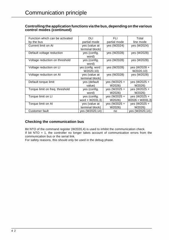
Controlling the application functions via the bus, depending on the variouscontrol modes (continued)
Function which can be activated DLI FLI Totalby the bus partial mode partial mode line modeCurrent limit on AI yes (value at yes (W2024) yes (W2024)
terminal block)Default voltage reduction yes (config. yes (W2028) yes (W2028)
word)Voltage reduction on threshold yes (config. yes (W2028) yes (W2028)
word)Voltage reduction on LI yes (config. word : yes (W2028) yes (W2028 +
W2020,10) W2020,10)Voltage reduction on AI yes (value at yes (W2028) yes (W2028)
terminal block)Default torque limit yes (default yes (W2025 + yes (W2025 +
value) W2026) W2026)Torque limit on freq. threshold yes (config. yes (W2025 + yes (W2025 +
word) W2026) W2026)Torque limit on LI yes (config. yes (W2025 + yes (W2025 +
word + W2031,3) W2026) W2026 + W2031,3)Torque limit on AI yes (value at yes (W2025 + yes (W2025 +
terminal block) W2026) W2026)Customer fault yes (W2020,14) no yes (W2020,14)
Checking the communication bus
Bit NTO of the command register (W2020,4) is used to inhibit the communication check.If bit NTO = 1, the controller no longer takes account of communication errors from thecommunication bus or the serial link.For safety reasons, this should only be used in the debug phase.
Communication principle
4 3
Altivar 66 variables
Altivar 66 variablesCertain Altivar 66 variables can be accessed at two different addresses :• in the 200 to 3000 address zone reserved for the Altivar 66,• in the 0 to 127 address zone already used by the Altivar 45.2.
1– Address zone reserved for the Altivar 66 (200 to 3000)This address zone contains all the speed controller parameters for optimum use of the facilitiesof the Altivar 66.
2– Address zone (0 to 127) common to the Altivar 66 and the Altivar 45.2This address zone should only be used when integrating an Altivar 66 into a control system whichuntil now has only included Altivar 45.2 controllers. Not all of the Altivar 66 parameters appearhere, in particular those functions available using the Altivar 66 but not the Altivar 45.2. In certaincases, using these addresses avoids the necessity of modifying the program.Any small differences in comparison with the Altivar 45.2 are indicated in the comments.
RangeThe range permitted by the speed controller is specified for each parameter.Writing of an incorrect value is always accepted, but will be automatically adjusted by the speedcontroller.
UnitWords are always expressed as integer values, either signed (-32768 to +32767) or unsigned(0 to 65535). The unit is defined for each of them.
Example : W2000 : high speed, unit = 0.1 Hz, W2000 : 455 corresponds to high speed = + 45.5 Hz.
Values on switching onEach time it is switched on the Altivar 66 is initialized with the configuration and adjustmentsstored in its EEPROM memory.

44
COMMANDS
ADJUSTMENT WORDS (read and write)
These parameters may be adjusted with the motor stopped or running .
WORD RANGE UNIT DESCRIPTION PRESETW1993 0…9999 Proportional gain 100W1994 0…9999 Integral gain 0W1995 -9999…9999 Gain 9999W1996 -4096…4096 Offset 0W1997 0…9999 Fault ratio 100W1998 0…9999 Keypad PI set point value 0W1999 0…600 0.1Hz Keypad speed reference value 0W2000 W2001…W301 0.1Hz High speedW2001 W*…W2000 0.1Hz Low speedW2002 1...9999 0.1s 1st acceleration ramp time 3 sW2003 1...9999 0.1s 1st deceleration ramp time 3 sW2004 1...9999 0.1s 2nd acceleration ramp time 5 sW2005 1...9999 0.1s 2nd deceleration ramp time 5 sW2006 1...100 0.1Hz Slip compensation : motor value 3 HzW2007 0...800 ** 1 % IR compensation 100 %W2008 0...100 1 % Profile 20 %W2009 0...100 1 % BOOST voltage 20 %W2010 0...800 ** 1 % Damping 20 %W2011 0...100 0.1% Bandwidth 20 %W2012 45%Invar...115%Invar 0.1 A Thermal protection Nominal motor current 1
(W214)
W* = Max. between W247 and W250
** Depends on torque type : – High torque ....... 150– Special .............. 800– Other ................. 100
In Var : W2205.
Altivar 66 variables

45
COMMANDS
COMMAND WORDS (read and write)
Command registerWORD DESCRIPTION POSSIBLE VALUES
W2020 Speed controller reset W2020,0 = 0 no requestW2020,0 = 1 reset request
Assignment of logic commands W2020,1 = 0 logic commands in local modein line mode (DLI) W2020,1 = 1 logic commands in line modeAssignment of set points in line mode (FLI) W2020,2 = 0 set point in local mode
W2020,2 = 1 set point in line modeRamp 2 command W2020,3 = 0 ramp 1 command
W2020,3 = 1 ramp 2 commandCommunication check inhibited (NTO) W2020,4 = 0 communication check activated
W2020,4 = 1 communication check disactivatedStart/Stop command (RUN) W2020,5 = 0 stop request
W2020,5 = 1 start requestDC injection braking command (DCB) W2020,6 = 0 no DC injection
W2020,6 = 1 DC injection commandSelect orient stop W2020,7 = 0 select orient stop
W2020,7 = 1 select normal stop(warning : operation reversed compared to freewheel andfast stops)
Select freewheel stop W2020,8 see table belowSelect fast stop W2020,9 see table belowVoltage reduction command W2020,10 = 0 no voltage reduction
W2020,10 = 1 voltage reduction according to thecommanded or configured value
Select motor a W2020,11 see table belowSelect motor b W2020,12 see table belowReserved W2020,13External fault command (EFL) W2020,14 = 0 no external fault
W2020,14 = 1 external fault presentReserved W2020,15
Important : it is imperative to set the bits (1 and 2) of word W2020 to 1 to access the logic commandsand the ATV set point via serial link.It is necessary to activate LI1 to start the motor.The DLI and FLI bits are accepted first when writing.
Freewheel stop (W2020.8) Fast stop (W2020.9) Stop on stop request (W2020.5 = 0 1)0 0 Normal stop1 1 Freewheel stop1 0 Freewheel stop0 1 Fast stop
Select motor a (W2020.11) Select motor b (W2020.12) * *0 0 motor 1 1 parameter1 0 motor 2 2 parameters0 1 motor 3 3 parameters1 1 No switching No switching
* Depending on the configuration selected (multiparameter or multimotor)
Altivar 66 variables

46
COMMANDS
Altivar 66 variablesCOMMAND WORDS (read and write)
Additional command registerWORD DESCRIPTION POSSIBLE VALUES
W2031 Current limit command W2031,0 = 0 default limitW2031,0 = 1 current limit depending on the configured or commanded value
Operating direction W2031,1 = 0 run forwardW2031,1 = 1 run reverse
Auto / man command W2031,2 = 0 auto set pointW2031,2 = 1 man set point
Motor and generator torque limit W2031,3 = 0 default limitcommand W2031,3 = 1 torque limit depending on the
configured or commanded values
Preset speeds selection a W2031,4 see table below
Preset speeds selection b W2031,5 see table below
Preset speeds selection c W2031,6 see table below
Reserved W2031,7 –> W2031,15
Selection a Selection b Selection c Number of preset speeds
0 0 0 no preset speed
1 0 0 1 preset speed
0 1 0 2 preset speeds
1 1 0 3 preset speeds
0 0 1 4 preset speeds
1 0 1 5 preset speeds
0 1 1 6 preset speeds
1 1 1 7 preset speeds
Frequency set point in line modeWORD RANGE UNIT DESCRIPTION POSSIBLE VALUES
W2021 -32767 .. 32767 - frequency set point in line mode 26478 represents 400 Hz-26478 represents -400 Hz
Current and torque limit and voltage reductionWORD RANGE UNIT DESCRIPTION POSSIBLE VALUES
W2024 400...1500 0.1 % Current limit value value expressed as a % of the nominalmotor current
W2025 0...200% 1 % Motor torque limit value
W2026 0...200% 1 % Generator torque limitvalue
W2027 Reserved
W2028 20…100 % 1 % Motor voltage reduction value expressed as a % of the nominalvalue motor voltage

47
COMMANDS
Altivar 66 variablesCOMMAND WORDS (read and write)
Analog and logic output commandWORD RANGE UNIT DESCRIPTION POSSIBLE VALUES
W2022 Reserved W2022,0
State of logic output LO1 W2022,1=0 low state W2022,1=1 high state
State of logic output LO2 W2022,2=0 low state W2022,2=1 high state
Reserved W2022,3 and W2022,4
State of output relay RO2 W2022,5=0 low state W2022,5=1 high state
State of output relay RO3 W2022,6=0 low state W2022,1=1 high state
State of output relay RO4 W2022,7=0 low state W2022,1=1 high state
W2023 0…4095 Value of output AO1 Depends on type of signal configured :
W2029 0…4095 Value of output AO2 0 corresponds to 0 mA or 4 mA
W2030 0…4095 Value of output AO3 4095 corresponds to 20 mA
Important : outputs LO, RO, and AO must be deactivated before use.

48
SIGNALLING
Altivar 66 variablesSIGNALLING WORDS (read-only)
Status registerWORD DESCRIPTION POSSIBLE VALUES
W2040 All commands W2040,0 = 0 Commands assigned in line mode
assigned in LOCAL mode W2040,0 = 1 All commands assigned in local mode
(terminal block or keypad)
Speed controller ready W2040,1 = 0 Speed controller not ready
(RDY or SLC) W2040,1 = 1 Speed controller ready
Faulty (FLT) W2040,2 = 0 No speed controller fault
W2040,2 = 1 Speed controller faulty
Reset authorized W2040,3 = 0 Reset not authorized
W2040,3 = 1 Reset authorized
Brake release relay W2040,4 = 0 Brake release relay not energized
energized W2040,4 = 1 Brake release relay energized
Speed controller forced W2040,5 = 0 Speed controller not forced
in LOCAL mode W2040,5 = 1 Speed controller forced in LOCAL mode
Communication check W2040,6 = 0 Communication fault monitoring
inhibited (NTO) W2040,6 = 1 No communication fault monitoring
Resettable fault W2040,7 = 0 Speed controller has no resettable fault
W2040,7 = 1 Speed controller has resettable fault
Motor running W2040,8 = 0 Motor stopped
W2040,8 = 1 Motor running
Actual direction of rotation W2040,9 = 0 Forward operation
W2040,9 = 1 Reverse operation
DC injection braking W2040,10 = 0 No current injection
W2040,10 = 1 Current injection in progress
Steady state W2040,11 = 0 Speed controller not in steady state
W2040,11 = 1 Speed controller in steady state
Motor thermal overload W2040,12 = 0 Speed controller has no motor overload fault
alarm W2040,12 = 1 Speed controller has motor overload fault
Overbraking alarm W2040,13 = 0 Speed controller has no DC bus overvoltage fault
W2040,13 = 1 Speed controller has DC bus overvoltage fault
Current limit W2040,14 = 0 Speed controller not in current limit
W2040,14 = 1 Speed controller in current limit
No power present W2040,15 = 0 Speed controller has no AC phase failure
(NLP) W2040,15 = 1 Speed controller has AC phase failure

49
SIGNALLING
SIGNALLING WORDS (read-only)
Complimentary status registerWORD DESCRIPTION POSSIBLE VALUES
W2047 Local control mode W2047,0 = 0 Local control via terminal block
terminal block/keypad W2047,0 = 1 Local control via keypad
On line logic W2047,1 = 0 On line logic commands not activated
commands W2047,1 = 1 On line logic commands activated
On line set point W2047,2 = 0 On line set point commands not activated
commands W2047,2 = 1 On line set point commands activated
Dynamic braking W2047,3 = 0 Braking not active
(BRK) W2047,3 = 1 Braking active
Fast stop in progress W2047,4 = 0 Fast stop not in progress
W2047,4 = 1 Fast stop in progress
Controlled stop on loss W2047,5 = 0 Stop not in progress
of AC supply W2047,5 = 1 Stop in progress
Output voltage deactivated W2047,6 = 0 Power bridge controlled
freewheel stop W2047,6 = 1 Power bridge not controlled
Orient complete W2047,7 = 0 Oriented stop is incomplete or not in progress
W2047,7 = 1 Oriented stop is complete (function operates for 1 sec)
Decelerating (DEC) W2047,8 = 0 Speed controller not in deceleration phase
W2047,8 = 1 Speed controller in deceleration phase
Accelerating (ACC) W2047,9 = 0 Speed controller not in acceleration phase
W2047,9 = 1 Speed controller in acceleration phase
Motor selection W2047,10 State of motor selection or parameter set (a)
Motor selection W2047,11 State of motor selection or parameter set (b)
Reserved W2047,12
Speed controller thermal W2047,13 = 0 Speed controller has no thermal overload fault
alarm W2047,13 = 1 Speed controller has thermal overload fault
Reserved W2047,14
Stopped via the keypad W2047,15 = 0 Speed controller has not been stopped by keypad
W2047,15 = 1 Speed controller has been stopped by keypad (valid
from the deceleration phase)
Altivar 66 variables

50
SIGNALLING
Altivar 66 variablesSIGNALLING WORDS (read-only)
Complimentary status registerWORD DESCRIPTION POSSIBLE VALUES
W2048 JOG in progress W2048,0 = 0 JOG function not in progress
W2048,0 = 1 JOG function in progress
Shutdown completed W2048,1 = 0 Shutdown not completed
W2048,1 = 1 Shutdown completed
Cycle completed W2048,2 = 0 Cycle function not completed
W2048,2 = 1 Cycle function completed
Ramp 2 in progress W2048,3 = 0 Ramp 1
W2048,3 = 1 Ramp 2
Auto/Man state W2048,4 = 0 Manual activated
W2048,4 = 1 Automatic activated
Frequency threshold 1 reached W2048,5 = 0 Frequency threshold 1 not reached
W2048,5 = 1 Frequency threshold 1 reached
Frequency threshold 2 reached W2048,6 = 0 Frequency threshold 2 not reached
W2048,6 = 1 Frequency threshold 2 reached
Current threshold 1 reached W2048,7 = 0 Current threshold 1 not reached
W2048,7 = 1 Current threshold 1 reached
Current threshold 2 reached W2048,8 = 0 Current threshold 2 not reached
W2048,8 = 1 Current threshold 2 reached
Thermal threshold 1 reached W2048,9 = 0 Thermal threshold 1 not reached
W2048,9 = 1 Thermal threshold 1 reached
Thermal threshold 2 reached W2048,10 = 0 Thermal threshold 2 reached
W2048,10 = 1 Thermal threshold 2 reached
No ramp follow W2048,11 = 0 Ramp follow
W2048,11 = 1 No ramp follow
External contactor in active state W2048,12 = 0 Contactor not activated (Bypass mode)
W2048,12 = 1 Contactor activated (Bypass mode)
Direction of rotation requested W2048,13 = 0 Forward operation
W2048,13 = 1 Reverse operation
WORD DESCRIPTION POSSIBLE VALUES
W2049 Speed controller locked when W2049,0 = 0 Speed controller not locked when stopped
stopped W2049,0 = 1 Speed controller locked when stopped
Invalid configuration W2049,1 = 0 Valid configuration
W2049,1 = 1 Invalid configuration
OEM access protection indicator W2049,2 = 0 not protected
W2049,2 = 1 protected
State of configuration semaphore W2049,4 = 0 Semaphore free
W2049,4 = 1 Semaphore reserved
State of command semaphore W2049,5 = 0 Semaphore free
W2049,5 = 1 Semaphore reserved

51
SIGNALLING
SIGNALLING WORDS (read-only)
Register of faultsWORD POSSIBLE VALUESW2050 = 0 No fault
= 1 AC line overvoltage= 2 DC bus overvoltage= 3 DC bus undervoltage= 4 Ground fault= 5 Phase short-circuit= 6 ± 15 V supply= 7 Rating not recognized= 8 AC supply phase failure= 9 Motor overload= 10 Customer fault= 11 Speed controller thermal overload= 12 Overspeed= 13 Tachogenerator feedback loss= 14 Serial link loss= 15 Loss follower= 16 Memory failure= 17 DC bus load= 18 Isolation timeout (Bypass)= 19 Process timeout (Bypass)= 20 DB resistor absent= 21 DB resistor thermal protection= 22 Transistor short-circuit= 23 Open transistor= 24 Output phase loss= 25 Control card supply= 26 Peak current limit= 27 Reserved= 28 Disconnection of an I/O card= 29 Backdriving fault
Register of faults present (bit at 1 : fault present)WORD POSSIBLE VALUESW2051 W2051,0 Unlisted internal + other ATV66 fault
W2051,1 Serial link breakW2051,2 ReservedW2051,3 ReservedW2051,4 DC bus undervoltageW2051,5 AC supply overvoltageW2051,6 In-phase lossW2051,7 Speed controller overtemperatureW2051,8 Speed feedback not present, overspeedW2051,9 Phase short-circuit or ground short-circuitW2051,10 DC bus overvoltageW2051,11 ReservedW2051,12 Motor overloadW2051,13 Output phase lossW2051,14 ReservedW2051,15 Precharge failure
Altivar 66 variables

52
SIGNALLING
SIGNALLING WORDS (read-only)
Altivar 66 variables
WORD DESCRIPTION POSSIBLE VALUES
W2140 Indicates position of marker from 0 to 9
on 1 of the 8 past faults
W2141 Past fault 1 : speed controller status = 0 No fault
W2143 Past fault 2 : speed controller status = 1 Acceleration
W2145 Past fault 3 : speed controller status = 2 Deceleration
W2147 Past fault 4 : speed controller status = 3 Steady state
W2149 Past fault 5 : speed controller status = 4 Dynamic braking
W2151 Past fault 6 : speed controller status = 5 Ready
W2153 Past fault 7 : speed controller status = 6 DC injection
W2155 Past fault 8 : speed controller status = 7 Current limit
= 8 Reserved
= 9 Reserved
=10 Locking on run permitted
=11 Faulty
=12 Jog
W2142 Past fault 1 : fault name = 0 No fault
W2144 Past fault 2 : fault name = 1 AC supply overvoltage
W2146 Past fault 3 : fault name = 2 DC bus overvoltage
W2148 Past fault 4 : fault name = 3 DC bus undervoltage
W2150 Past fault 5 : fault name = 4 Earth fault
W2152 Past fault 6 : fault name = 5 Phase short-circuit
W2154 Past fault 7 : fault name = 6 Power supply ± 15 V
W2156 Past fault 8 : fault name = 7 Rating not recognized
= 8 One phase missing= 9 Motor overload= 10 User fault= 11 Speed controller thermal overload= 12 Overspeed= 13 Tachogenerator feedback loss= 14 Serial link loss= 15 Loss of 4-20 mA current input= 16 Memory fault= 17 DC bus load= 18 Isolation timeout (Bypass)= 19 Process timeout (Bypass)= 20 Braking resistor missing= 21 Thermal protection of braking resistor= 22 Transistor short-circuit= 23 Transistor open= 24 Motor phase fault= 25 Control card supply= 26 Peak current limit= 27 Reserved= 28 Disconnection of an I/O card= 29 Back driving fault

53
SIGNALLING
SIGNALLING WORDS (read-only)
WORD RANGE UNIT DESCRIPTION POSSIBLE VALUES
W2041 -32768...32767 Output frequency 400 Hz = 26478
W2042 0.1 A Output current
W2052 0.1 kW Output power
W2053 1 V Output voltage
W2054 1 V Supply voltage
W2055 1 V Bus voltage
W2056 1 % Motor thermal state value
W2057 1 % Speed controller thermal state value For rating > 7.5 kW
W2058 H Motor running time elapsed Total time = W2058, W2059
(hours)
W2059 min Motor running time elapsed
(minutes)
W2060 rpm Output speed
W2061 Machine speed reference Frequency set point x scale
(customer unit) factor (W734)
W2062 Machine frequency (customer unit) Output frequency x scale
factor (W734)
Altivar 66 variables

54
SIGNALLING
SIGNALLING WORDS (read-only)
WORD RANGE UNIT DESCRIPTION COMMENTS
W2074 0...2 No. of motor running or = 0 Motor 1set parameter number = 1 Motor 2
= 2 Motor 3
W2075 1...8 Current cycle step = 1 step 1= 2 step 2= 3 step 3= 4 step 4= 5 step 5= 6 step 6= 7 step 7= 8 step 8
W2076 0...7 Current preset speed number = 0 set point= 1 preset speed 1= 2 preset speed 2= 3 preset speed 3= 4 preset speed 4= 5 preset speed 5= 6 preset speed 6= 7 preset speed 7
* Depending on the configuration selected (either multimotor, or multiparameter).
WORD RANGE DESCRIPTION POSSIBLE VALUES
W2200 0...22 Commercial rating for speed controller = 0 Not significantin constant torque = 1 Reserved
= 2 Reserved= 3 Speed controller 2.2 kW - 3 HP= 4 Speed controller 3 kW - 4 HP= 5 Speed controller 4 kW - 5 HP= 6 Speed controller 5.5 kW - 7.5 HP= 7 Speed controller 7.5 kW - 10 HP= 8 Speed controller 11 kW - 15 HP= 9 Speed controller 15 kW - 20 HP= 10 Reserved= 11 Speed controller 22 kW - 30 HP= 12 Speed controller 30 kW - 40 HP= 13 Speed controller 37 kW - 50 HP= 14 Speed controller 45 kW - 60 HP= 15 Speed controller 55 kW - 75 HP= 16 Speed controller 75 kW - 100 HP= 17 Speed controller 90 kW - 125 HP= 18 Speed controller 110 kW - 150 HP= 19 Speed controller 132 kW - 200 HP= 20 Speed controller 160 kW - 250 HP= 21 Speed controller 200 kW - 300 HP= 22 Speed controller 220 kW - 350 HP= 23 Reserved
Altivar 66 variables

55
SIGNALLING
SIGNALLING WORDS (read-only)
WORD RANGE UNIT DESCRIPTION COMMENTS
W2201 0...23 Configured speed controller rating Same as previous rating with
= 1 Speed controller 0.75 kW - 1HP
= 2 Speed controller 1.5 kW - 2 HP
= 10 Speed controller 18.5 kW - 20 HP
= 23 Speed controller 250 kW - 400 HP
W2202 Speed controller voltage range = 0 Not significant
= 1 Voltage 208 - 240 V
= 2 Voltage 380 - 460 V
W2203 AC frequency recognized or not = 0 Not known
= 1 50 Hz
= 2 60 Hz
W2205 0.1A Altivar nominal current Depending on the rating, AC
voltage and torque type
W2206 0.1A Speed controller maximum current Depending on the rating, AC
voltage and torque type
W2071 Motor nominal voltage = 0 Voltage 208 - 240 V
= 1 Voltage 380 - 415 V
= 2 Voltage 440 - 460 V
WORD RANGE UNIT DESCRIPTION POSSIBLE VALUES
W2211 0...1 Memory card present = 0 Absent
= 1 Present
W2212 0...1 Communication Interface Option = 0 Non connected
= 1 Connected
W2213 0...1 Graphic keypad present = 0 Non connected
= 1 Connected
W2214 0...3 I/O option present = 0 No option
= 1 24 V DC option card
= 2 115 V AC option card
W2216 -1...5 PCMCIA communication card type = 0 No option
= 1 UNI-TELWAY / Modbus/Jbus
= 2 Reserved
= 3 FIP I/O
= 4 Modbus +
= 5 INTERBUS S
= -1 Unknown option
Altivar 66 variables

56
SIGNALLING
Altivar 66 variablesSIGNALLING WORDS (read-only)
WORD DESCRIPTION POSSIBLE VALUES
W2043 Display of activation of LI1 W2043,1 = 0 Input inactive
W2043,1 = 1 Input active
Display of activation of LI2 W2043,2 = 0 Input inactive
W2043,2 = 1 Input active
Display of activation of LI3 W2043,3 = 0 Input inactive
W2043,3 = 1 Input active
Display of activation of LI4 W2043,4 = 0 Input inactive
W2043,4 = 1 Input active
Display of activation of LI5 W2043,5 = 0 Input inactive
W2043,5 = 1 Input active
Display of activation of LI6 W2043,6 = 0 Input inactive
W2043,6 = 1 Input active
Display of activation of LI7 W2043,7 = 0 Input inactive
W2043,7 = 1 Input active
Display of activation of LI8 W2043,8 = 0 Input inactive
W2043,8 = 1 Input active
Display of activation of LO1 W2043,9 = 0 Input inactive
W2043,9 = 1 Input active
Display of activation of LO2 W2043,10 = 0 Input inactive
W2043,10 = 1 Input active
Display of activation of R1 W2043,11 = 0 Input inactive
W2043,11 = 1 Input active
Display of activation of R2 W2043,12 = 0 Input inactive
W2043,12 = 1 Input active
Display of activation of R3 W2043,13 = 0 Input inactive
W2043,13 = 1 Input active
Display of activation of R4 W2043,14 = 0 Input inactive
W2043,14 = 1 Input active
57
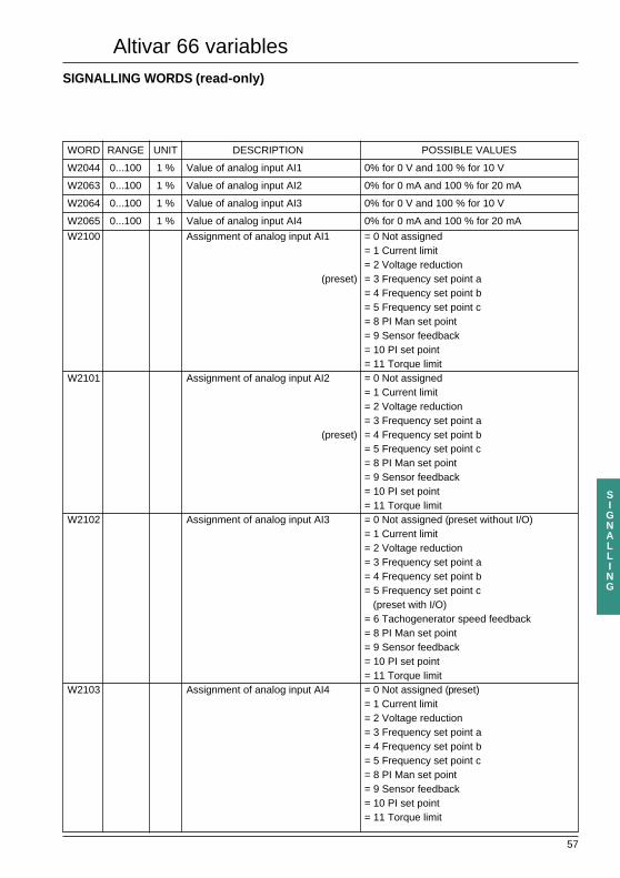
SIGNALLING
SIGNALLING WORDS (read-only)
WORD RANGE UNIT DESCRIPTION POSSIBLE VALUES
W2044 0...100 1 % Value of analog input AI1 0% for 0 V and 100 % for 10 V
W2063 0...100 1 % Value of analog input AI2 0% for 0 mA and 100 % for 20 mA
W2064 0...100 1 % Value of analog input AI3 0% for 0 V and 100 % for 10 V
W2065 0...100 1 % Value of analog input AI4 0% for 0 mA and 100 % for 20 mA
W2100 Assignment of analog input AI1 = 0 Not assigned= 1 Current limit= 2 Voltage reduction
(preset) = 3 Frequency set point a= 4 Frequency set point b= 5 Frequency set point c= 8 PI Man set point= 9 Sensor feedback= 10 PI set point= 11 Torque limit
W2101 Assignment of analog input AI2 = 0 Not assigned= 1 Current limit= 2 Voltage reduction= 3 Frequency set point a
(preset) = 4 Frequency set point b= 5 Frequency set point c= 8 PI Man set point= 9 Sensor feedback= 10 PI set point= 11 Torque limit
W2102 Assignment of analog input AI3 = 0 Not assigned (preset without I/O)= 1 Current limit= 2 Voltage reduction= 3 Frequency set point a= 4 Frequency set point b= 5 Frequency set point c (preset with I/O)= 6 Tachogenerator speed feedback= 8 PI Man set point= 9 Sensor feedback= 10 PI set point= 11 Torque limit
W2103 Assignment of analog input AI4 = 0 Not assigned (preset)= 1 Current limit= 2 Voltage reduction= 3 Frequency set point a= 4 Frequency set point b= 5 Frequency set point c= 8 PI Man set point= 9 Sensor feedback= 10 PI set point= 11 Torque limit
Altivar 66 variables

58
SIGNALLING
Altivar 66 variablesSIGNALLING WORDS (read-only)
Display of assignment of analog outputsWORD RANGE DESCRIPTION POSSIBLE VALUES
W2104 Assignment of analog output AO1 = 0 Not assigned
= 1 Motor current
(preset) = 2 Motor frequency
= 3 Output power
= 4 Motor torque
= 5 Output voltage
= 6 Motor thermal state
= 7 Ramp output
= 8 PI set point
= 9 Sensor feedback
= 10 PI error
= 11 PI error integrator
W2105 Assignment of analog output AO2 = 0 Not assigned
(preset) = 1 Motor current
= 2 Motor frequency
= 3 Output power
= 4 Motor torque
= 5 Output voltage
= 6 Motor thermal state
= 7 Ramp output
= 8 PI set point
= 9 Sensor feedback
= 10 PI error
= 11 PI error integrator
W2106 Assignment of analog output AO3 (preset) = 0 Not assigned
= 1 Motor current
= 2 Motor frequency
= 3 Output power
= 4 Motor torque
= 5 Output voltage
= 6 Motor thermal state
= 7 Ramp output
= 8 PI set point
= 9 Sensor feedback
= 10 PI error
= 11 PI error integrator
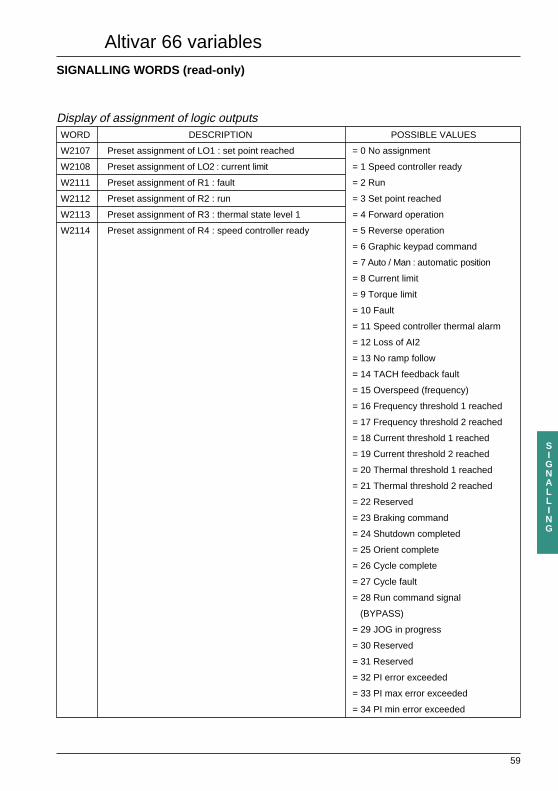
59
SIGNALLING
Altivar 66 variablesSIGNALLING WORDS (read-only)
Display of assignment of logic outputsWORD DESCRIPTION POSSIBLE VALUES
W2107 Preset assignment of LO1 : set point reached = 0 No assignment
W2108 Preset assignment of LO2 : current limit = 1 Speed controller ready
W2111 Preset assignment of R1 : fault = 2 Run
W2112 Preset assignment of R2 : run = 3 Set point reached
W2113 Preset assignment of R3 : thermal state level 1 = 4 Forward operation
W2114 Preset assignment of R4 : speed controller ready = 5 Reverse operation
= 6 Graphic keypad command
= 7 Auto / Man : automatic position
= 8 Current limit
= 9 Torque limit
= 10 Fault
= 11 Speed controller thermal alarm
= 12 Loss of AI2
= 13 No ramp follow
= 14 TACH feedback fault
= 15 Overspeed (frequency)
= 16 Frequency threshold 1 reached
= 17 Frequency threshold 2 reached
= 18 Current threshold 1 reached
= 19 Current threshold 2 reached
= 20 Thermal threshold 1 reached
= 21 Thermal threshold 2 reached
= 22 Reserved
= 23 Braking command
= 24 Shutdown completed
= 25 Orient complete
= 26 Cycle complete
= 27 Cycle fault
= 28 Run command signal
(BYPASS)
= 29 JOG in progress
= 30 Reserved
= 31 Reserved
= 32 PI error exceeded
= 33 PI max error exceeded
= 34 PI min error exceeded

60
SIGNALLING
SIGNALLING WORDS (read-only)
Display of assignment of logic inputsWORD DESCRIPTION POSSIBLE VALUES
W2115 Assignment of LI1 : Stop (not reconfigurable) Depends on the 2-wire / 3-wire configuration
= 1 Stop (not reconfigurable)
= 2 Run (not reconfigurable)
W2116 Assignment of LI2 : Forward operation = 3 Forward operation (not reconfigurable)
(not reconfigurable)
W2117 Assignment of LI3 : Reverse operation = 0 Not assigned
W2118 Assignment of LI4 : JOG = 4 Reverse operation
W2119 Assignment of LI5 : Preset speed a = 5 Current limit
W2120 Assignment of LI6 : Preset speed b = 6 Voltage reduction
W2121 Assignment of LI7 : Preset speed c = 7 Ramp switching
W2122 Assignment of LI8 : Fault reset = 8 JOG
= 9 + speed
= 10 - speed
= 11 Controlled stop
= 12 Start cycle with I/O card
= 13 Reset cycle with I/O card
= 14 Cycle blocked with I/O card
= 15 Cycle next stop with I/O card
= 16 Set point memory
= 17 Preset speed a command
= 18 Preset speed b command
= 19 Preset speed c command with I/O card
= 20 Indexing command with I/O card
= 21 Indexing pulse with I/O card
= 22 Local control
= 23 Auto/man
= 24 Terminal block/keypad
= 25 Input assigned to process (Bypass)
= 26 Input assigned to starting (Bypass)
= 27 Parameter selection / motor a
= 28 Parameter selection / motor b
= 29 Customer fault
= 30 Reset fault (RAZ fault)
= 31 Run Auto
= 32 Reserved
= 33 Auto/Man (PI)
= 34 Reverse direction (PI)
= 35 Reserved
= 36 Torque limit
Altivar 66 variables

61
CONFIGURATION
CONFIGURATION WORDS (read and write)Access to variables management
Semaphores and locking when stoppedWORD RANGE DESCRIPTION COMMENTS
W198 Configuration semaphore 0 = Free
1 = Reserved
W199 Speed controller locked 0 = Not locked
when stopped 1 = Locked
W2235 Command semaphore 0 = Free
1 = Reserved
See section "Communication principle"
Access to speed controller adjustmentsWORD RANGE UNIT DESCRIPTION COMMENTS
W748 Type of access to speed controller data 0 = Partial access
via keypad 1 = Total access
Altivar 66 variables

62
CONFIGURATION
CONFIGURATION WORDS (read and write)Basic configuration of speed controller and motor
WORD RANGE UNIT DESCRIPTION POSSIBLE VALUES
W211 Motor nominal frequency type = 0 Frequency 50 Hz
= 1 Frequency 60 Hz
= 2 Special frequency
WORD RANGE UNIT DESCRIPTION POSSIBLE VALUES
W212 25...Fmax VAR 1Hz Motor nominal frequency
WORD RANGE UNIT DESCRIPTION POSSIBLE VALUES
W301 W212...Fmax VAR 0.1Hz Motor maximum frequency
High speedWORD RANGE UNIT DESCRIPTION POSSIBLE VALUES
W302 W303...W301 0.1Hz High speed 50 Hz if 50 Hz supply60 Hz if 60 Hz supply
Low speedWORD RANGE UNIT DESCRIPTION POSSIBLE VALUES
W303 0...W302 0.1Hz Low speed Preset at 0.0 Hz
WORD RANGE UNIT DESCRIPTION POSSIBLE VALUES
W213 Motor nominal voltage = 0 Nominal voltage 208 V= 1 Nominal voltage 220 V= 2 Nominal voltage 230 V
Preset supply voltage = 3 Nominal voltage 240 V= 4 Nominal voltage 380 V
Preset 50Hz supply = 5 Nominal voltage 400 V= 6 Nominal voltage 415 V= 7 Nominal voltage 440 V
Preset 60 Hz supply = 8 Nominal voltage 460 V
WORD RANGE UNIT DESCRIPTION POSSIBLE VALUES
W214 45% Inom VAR 0.1A Motor nominal current Preset at In 0.9 speed controller
105% Inom VAR
VAR nominal current depends on the torque type, supply frequency, speed controller rating and motor ratingF max VAR :Constant torque : 400 Hz for Altivar 66 U41N4 to D79N4
Altivar 66 U41M2 to D46M2 200 Hz for Altivar 66 C10N4 to C31N4
Variable torque : 75/90 Hz (50 Hz/60Hz supply)
WORD RANGE UNIT DESCRIPTION
W219 300…24000 rpm Motor nominal speed configuration
* When the multi-motor function is being used, nominal speed configuration by motor 2 is done
via word W419 and for motor 3 via word W619.
Altivar 66 variables

63
CONFIGURATION
CONFIGURATION WORDS (read and write)Basic configuration of speed controller and motor
WORD DESCRIPTION POSSIBLE VALUES
W200 2- or 3-wire control = 0 2-wire control (preset)= 1 3-wire control
W201 Torque type = 0 Constant torque (preset)= 1 Variable torque= 2 Low noise variable torque
W206 Control type = 0 Normal control (preset)= 1 NOLD control= 2 High torque control= 3 Special motor control
W202 Motor power = 1 Motor 0.75 kW - 1 HPOnly applicable to U41 rating = 2 Motor 1.5 kW - 2 HP (preset) = 3 Motor 2.2 kW - 3 HP
W210 Direction of phase rotation W210,1 = 0 Phase rotation ABC (preset)
W210,1 = 1 Phase rotation ACB
Configuration of torque limitWORD RANGE UNIT DESCRIPTION COMMENTS
W320 Torque limit type = 0 Torque limit by fault= 1 Torque limit by logic input= 2 Torque limit by analog input
W321 Torque limit assignment of = 0 No logic input assignedactivating logic input = 1 Reserved
= 2 Reserved= 3 Logic input LI3 on basic product= 4 Logic input LI4 on basic product= 5 Logic input LI5 (I/O card)= 6 Logic input LI6 (I/O card)= 7 Logic input LI7 (I/O card)= 8 Logic input LI8 (I/O card)
W322 Torque limit assignment of = 0 No analog input assignedactivating analog input = 1 Analog input AI1
= 2 Analog input AI2= 3 Analog input AI3 (I/O card)= 4 Analog input AI4 (I/O card)
W215 0...200 1% Torque limit in generator Only in constant torque HIGH TORQUEor phase (preset at 200%)
W323
W216 0...200 1% Torque limit in motor Only in constant torque HIGH TORQUEor phase (preset at 200%)
W324
Altivar 66 variables

64
CONFIGURATION
Altivar 66 variablesCONFIGURATION WORDS (read and write)
Configuration of slip compensationWORD RANGE UNIT DESCRIPTION POSSIBLE VALUES
W225 Enabling of slip compensation W225,0 = 0 Function not enabled
W225,0 = 1 Function enabled
W226 Slip compensation type = 0 No compensation
(preset) = 1 Automatic compensation
= 2 Manual compensation
W227 1..100 0.1Hz Slip compensation value Preset at 3.0 Hz
WORD RANGE UNIT DESCRIPTION POSSIBLE VALUES
W228 0...IR 1% IR compensation value Only for constant torque, preset at 100%
Comp max
Max IR comp : Depends on control type : - High torque…150 %
- Special…800 %
- Normal…100 %
WORD RANGE UNIT DESCRIPTION POSSIBLE VALUES
W229 0...100 1% Profile Only for variable torque and if NORMAL
has been selected (preset at 20 %)
WORD RANGE UNIT DESCRIPTION POSSIBLE VALUES
W230 0...100 1% Voltage boost Only for constant torque HIGH TORQUE
or SPECIAL (preset at 20%)
WORD RANGE UNIT DESCRIPTION POSSIBLE VALUES
W231 1...Stab 1% Damping Preset at 20%
max
Max. damping : 800 % for Normal control variable torque and Special control constant torque
100 % otherwise
WORD RANGE UNIT DESCRIPTION POSSIBLE VALUES
W232 0...100 1% Bandwidth Only for constant torque control
HIGH TORQUE (preset at 20%)

65
CONFIGURATION
CONFIGURATION WORDS (read and write)
Configuration of braking sequenceWORD RANGE UNIT DESCRIPTION POSSIBLE VALUES
W245 Enabling of braking sequence W245,0 = 0 Function not enabled (preset)
W245,0 = 1 Function enabled
W246 Brake control logic output = 0 No logic output assigned
= 1 Logic output LO1
= 2 Logic output LO2
= 3 Reserved
= 4 Logic output R2
= 5 Logic output R3 (I/O card)
= 6 Logic output R4 (I/O card)
W247 0...W303 0.1Hz Brake dwell frequency From 0 to LS (low speed) Preset at 0 Hz
W248 0...W214 0.1 A Brake dwell current level From 0 to In (In = motor nominal current)
Preset at 0 A
W249 0...50 0.1s Brake dwell time Preset at 0.0 s
W250 0...W303 0.1Hz Brake release frequency Preset at 0.0 Hz
W251 0...50 0.1s Brake release time Preset at 0.0 s
W252 50...150 1% DC injection level Preset at 70 %
W253 0...301 0.1s DC injection time Preset at 2 s
Summary of analog inputsWORD RANGE DESCRIPTION POSSIBLE VALUES
W810 Limitation to 0 of the summing of W810,2 = 0 Function not enabled
analog inputs assigned to the W810,2 = 1 Function enabled (preset)
frequency set point
W811 Analog input : = 0 No analog input
frequency set point «a» = 1 Analog input AI1 (preset)
= 2 Analog input AI2
= 3 Analog input AI3 (I/O card)
= 4 Analog input AI4 (I/O card)
W812 Analog input : = 0 No analog input
frequency set point «b» = 1 Analog input AI1
= 2 Analog input AI2 (preset)
= 3 Analog input AI3 (I/O card)
= 4 Analog input AI4 (I/O card)
W813 Analog input : = 0 No analog input (preset)
frequency set point «c» = 1 Analog input AI1
= 2 Analog input AI2
= 3 Analog input AI3 (I/O card)
= 4 Analog input AI4 (I/O card) (preset)
Altivar 66 variables

66
CONFIGURATION
Altivar 66 variablesCONFIGURATION WORDS (read and write)
Configuration of current limitWORD RANGE UNIT DESCRIPTION POSSIBLE VALUES
W260 Enabling of current limit W260,0 = 0 Function not enabled (preset)
W260,0 = 1 Function enabled
W261 Current limit type = 0 No current limit (preset)= 1 Limit via frequency level= 2 Limit via logic input= 3 Limit via analog input
W262 Logic input to activate = 0 No logic input assigned current limit = 1 Reserved
= 2 Reserved= 3 Logic input LI3 on basic product= 4 Logic input LI4 on basic product= 5 Logic input LI5 (I/O card)= 6 Logic input LI6 (I/O card)= 7 Logic input LI7 (I/O card)= 8 Logic input LI8 (I/O card)
W263 Analog input for = 0 No analog inputcurrent limit = 1 Analog input AI1
= 2 Analog input AI2= 3 Analog input AI3 (I/O card)= 4 Analog input AI4 (I/O card)
W264 0... 0.1Hz Activation frequency Preset at 60 Hz if 60 Hz supplyFmax VAR level 50 Hz if 50 Hz supply
W265 40 % of 0.1A Limit current I xx depends on torque type selected, supply frequency I nom VAR and speed controller rating
...I xx Constant torque 60Hz ⇒ 150 %. I nom ATVConstant torque 50Hz ⇒ 136 %. I nom ATVVariable torque ⇒ 110 %. I nom ATV

67
CONFIGURATION
Altivar 66 variablesCONFIGURATION WORDS (read and write)
Configuration of acceleration and decelerationWORD RANGE UNIT DESCRIPTION POSSIBLE VALUES
W270 Enabling of ramp switching W270,0 = 0 Function not enabled (preset)(alternate ramp) W270,0 = 1 Function enabled
W271 Acceleration type = 0 Linear ramp (preset)= 1 S ramp= 2 U ramp
W272 0...100 1% Rounding coefficient for Preset at 20 %S acceleration ramps
W273 0...100 1% Rounding coefficient for Preset at 50 %U acceleration ramps
W274 Deceleration type = 0 Linear ramp (preset)= 1 S ramp= 2 U ramp
W275 0...100 1% Rounding coefficient for Preset at 20 %S deceleration ramps
W276 0...100 1% Rounding coefficient for Preset at 50 %U deceleration ramps
W277 Ramp switching type = 0 Not assigned (preset)(alternate ramp) = 1 Switching by frequency level
= 2 Switching by logic input
W278 Logic input for ramp = 0 No logic input (preset)switching = 1 Reserved
= 2 Reserved= 3 Logic input LI3 on basic product= 4 Logic input LI4 on basic product= 5 Logic input LI5 (I/O card)= 6 Logic input LI6 (I/O card)= 7 Logic input LI7 (I/O card)= 8 Logic input LI8 (I/O card)
W279 0...Fmax 0.1Hz Activation frequency level Preset at 30.0 HzVAR
W280 1...9999 0.1s Duration of first acceleration ramp Preset at 3.0 s
W281 1...9999 0.1s Duration of first deceleration ramp Preset at 3.0 s
W282 1...9999 0.1s Duration of second acceleration Preset at 5.0 sramp
W283 1...9999 0.1s Duration of second deceleration Preset at 5.0 sramp
Configuration of skip frequenciesWORD RANGE UNIT DESCRIPTION POSSIBLE VALUES
W290 Skip frequency range 1 W290,1 = 0 2 Hz (default)W290,1 = 1 5 Hz
Skip frequency range 2 W290,2 = 0 2 Hz (default)W290,2 = 1 5 Hz
Skip frequency range 3 W290,3 = 0 2 Hz (default)W290,3 = 1 5 Hz
W291 0...Fmax VAR 0.1Hz Skip frequency value 1 Preset at 0.0 Hz
W292 0...Fmax VAR 0.1Hz Skip frequency value 2 Preset at 0.0 Hz
W293 0...Fmax VAR 0.1Hz Skip frequency value 3 Preset at 0.0 Hz

68
CONFIGURATION
Altivar 66 variablesCONFIGURATION WORDS (read and write)
Configuration of reverse operation functionWORD RANGE UNIT DESCRIPTION POSSIBLE VALUES
W880 Enabling of reverse function W880,0 = 0 Function not enabled
W880,0 = 1 Function enabled (preset)
W881 Logic input for enabling = 0 No logic input assigned
Run / Reverse = 1 Reserved
= 2 Reserved
Preset = 3 Logic input LI3 on basic product
= 4 Logic input LI4 on basic product
= 5 Logic input LI5 (I/O card)
= 6 Logic input LI6 (I/O card)
= 7 Logic input LI7 (I/O card)
= 8 Logic input LI8 (I/O card)
Configuration of JOG functionWORD RANGE UNIT DESCRIPTION POSSIBLE VALUES
W890 Enabling of JOG function W890.0 = 0 Function not enabled
W890,0 = 1 Function enabled (preset)
W891 Logic input for JOG activation = 0 No logic input assigned
= 1 Reserved
= 2 Reserved
= 3 Logic input LI3 on basic product
Preset = 4 Logic input LI4 on basic product
= 5 Logic input LI5 (I/O card)
= 6 Logic input LI6 (I/O card)
= 7 Logic input LI7 (I/O card)
= 8 Logic input LI8 (I/O card)
W892 Logic output for signalling = 0 No logic output assigned (preset)
enabling of JOG = 1 Logic output LO1
= 2 Logic output LO2
= 3 Reserved
= 4 Logic output R2
= 5 Logic output R3 (I/O card)
= 6 Logic output R4 (I/O card)
W893 2...100 0.1Hz JOG set point frequency Preset at 5.0 Hz
W894 2...100 0.1s Dead time between two Preset at 0.5 s
JOG pulses

69
CONFIGURATION
CONFIGURATION WORDS (read and write)
Configuration of + speed / - speed functionWORD DESCRIPTION POSSIBLE VALUES
W820 Enabling of + speed / - speed function W820,0 = 0 Function not enabled (preset)
W820,0 = 1 Function enabled
W821 Type of + / - speed = 0 Function not enabled (preset)
= 1 Enabling with memorization of speed reference
= 2 Enabling without memorization of speed reference
W822 Logic input for - speed = 0 No logic output assigned (preset)
= 1 Reserved
= 2 Reserved
= 3 Logic input LI3 on basic product
= 4 Logic input LI4 on basic product
= 5 Logic input LI5 (I/O card)
= 6 Logic input LI6 (I/O card)
= 7 Logic input LI7 (I/O card)
= 8 Logic input LI8 (I/O card)
W823 Logic input for + speed = 0 No logic output assigned (preset)
= 1 Reserved
= 2 Reserved
= 3 Logic input LI3 on basic product
= 4 Logic input LI4 on basic product
= 5 Logic input LI5 (I/O card)
= 6 Logic input LI6 (I/O card)
= 7 Logic input LI7 (I/O card)
= 8 Logic input LI8 (I/O card)
Altivar 66 variables

70
CONFIGURATION
Altivar 66 variablesCONFIGURATION WORDS (read and write)
Configuration of preset speedsWORD RANGE UNIT DESCRIPTION POSSIBLE VALUES
W830 Enabling of preset W830,0 = 0 Function not enabled (preset)
speeds W830,0 = 1 Function enabled
(preset with I/O option)
W831 Choice of number of preset = 0 No preset speed (preset)
speeds = 1 One preset speed
= 2 Three preset speeds
= 3 Seven preset speeds
(preset with I/O option)
W832 Select via logic input (a) = 0 No logic input assigned (preset)
W833 Select via logic input (b) = 1 Reserved
W834 Select via logic input (c) = 2 Reserved
= 3 Logic input LI3 on basic product
= 4 Logic input LI4 on basic product
(preset)
= 5 Logic input LI5 (I/O card)
preset : (a) with I/O card
= 6 Logic input LI6 (I/O card)
preset : (b) with I/O card
= 7 Logic input LI7 (I/O card)
preset : (c) with I/O card
= 8 Logic input LI8 (I/O card)
W835 0...Fmax VAR 0.1Hz Speed 1 value Preset at 5.0 Hz
W836 W835…Fmax VAR 0.1Hz Speed 2 value Preset at10.0 Hz
W837 W836…Fmax VAR 0.1Hz Speed 3 value Preset at 15.0 Hz
W838 W837…Fmax VAR 0.1Hz Speed 4 value Preset at 20.0 Hz
W839 W838…Fmax VAR 0.1Hz Speed 5 value Preset at 25.0 Hz
W840 W839…Fmax VAR 0.1Hz Speed 6 value Preset at 30.0 Hz
W841 W840…Fmax VAR 0.1Hz Speed 7 value Preset at 35.0 Hz
F max VAR :Constant torque : 400 Hz for Altivar 66 U41N4 to D79N4
Altivar 66 U41M2 to D46M2 200 Hz for Altivar 66 C10N4 to C31N4Variable torque : 75/90 Hz (50 Hz/60Hz supply)
The value of preset speed 1 must be less than the value of preset speed 2,which must be less than the value of preset speed 3,which must be less than the value of preset speed 4,which must be less than the value of preset speed 5,which must be less than the value of preset speed 6,which must be less than the value of preset speed 7, whatever the number of preset speeds.

71
CONFIGURATION
CONFIGURATION WORDS (read and write)
Configuration of Auto/Man functionWORD DESCRIPTION POSSIBLE VALUES
W860 Auto/Man W860, 0 = 0 Not enabled (preset)
W860, 0 = 1 Enabled via logic input
W861 Auto / manual switching logic input = 0 No logic input assigned (preset)
= 1 Reserved
= 2 Reserved
= 3 Logic input LI3 on basic product
= 4 Logic input LI4 on basic product
= 5 Logic input LI5 (I/O card)
= 6 Logic input LI6 (I/O card)
= 7 Logic input LI7(I/O card)
= 8 Logic input LI8 (I/O card)
W862 Automatic run logic input = 0 No logic input assigned (preset)
= 1 Reserved
= 2 Reserved
= 3 Logic input LI3 on basic product
= 4 Logic input LI4 on basic product
= 5 Logic input LI5 (I/O card)
= 6 Logic input LI6 (I/O card)
= 7 Logic input LI7 (I/O card)
= 8 Logic input LI8 (I/O card)
Configuration of local forcing WORD RANGE UNIT DESCRIPTION COMMENTS
W910 Enabling of local forcing W910, 0 = Function not enabled (preset)
W910, 1 = Function enabled
W911 Local forcing via logic input = 0 No logic input assigned
= 1 Reserved
= 2 Reserved
= 3 Logic input LI3 on basic product
= 4 Logic input LI4 on basic product
= 5 Logic input LI5 (I/O card)
= 6 Logic input LI6 (I/O card)
= 7 Logic input LI7 (I/O card)
= 8 Logic input LI8 (I/O card)
Altivar 66 variables

72
CONFIGURATION
Altivar 66 variablesCONFIGURATION WORDS (read and write)
Configuration of controlled stop WORD RANGE UNIT DESCRIPTION POSSIBLE VALUES
W920 Enabling of controlled stop W920,0 = 0 Function not enabled (preset)
W920,0 = 1 Function enabled
Activation input active level W920,1 = 0 active at 0 (preset)
W920,1 = 1 active at 1
W921 Controlled stop : type of = 0 No controlled stop (preset)
input activation = 1 Activation via logic input
= 2 Activation on frequency level
= 3 Activation via logic input
or frequency level
W922 Stop command via logic input = 0 No logic input assigned (preset)
= 1 Reserved
= 2 Reserved
= 3 Logic input LI3 on basic product
= 4 Logic input LI4 on basic product
= 5 Logic input LI5 (I/O card)
= 6 Logic input LI6 (I/O card)
= 7 Logic input LI7 (I/O card)
= 8 Logic input LI8 (I/O card)
W923 Type of controlled stop activated = 0 Freewheel stop (preset)
via logic input = 1 Fast stop
= 2 DC injection stop
W924 Type of controlled stop activated = 0 Freewheel stop (preset)
via frequency level = 1 Fast stop
= 2 DC injection stop
W925 0…Fmax VAR 0.1 Hz Frequency level adjustment Preset at 0 Hz
W926 50…150 1% Percentage of DC current Preset at 70% (same as W955)
injected
W927 0…301 0.1 s Adjustment of DC current injection Preset at 2 s (same as W956)
time
F max VAR : (W2204)
Constant torque : 400 Hz for Altivar 66 U41N4 to D79N4
Altivar 66 U41M2 to D46M2
200 Hz for Altivar 66 C10N4 to C31N4
Variable torque : 75/90 Hz (50 Hz/60Hz supply)

73
CONFIGURATION
CONFIGURATION WORDS (read and write)
Configuration of shutdown WORD RANGE UNIT DESCRIPTION POSSIBLE VALUES
W940 Shutdown W940,0 = 0 Function not enabled (preset)
W940,0 = 1 Function enabled
W941 Logic output to signal = 0 No logic output assigned (preset)
shutdown completed = 1 Logic output LO1
= 2 Logic output LO2
= 3 Reserved
= 4 Logic output R2
= 5 Logic output R3 (I/O card)
= 6 Logic output R4 (I/O card)
W942 1...600 0.1s Low speed dwell time Preset at 1.0 s
Configuration of Bypass WORD RANGE UNIT DESCRIPTION POSSIBLE VALUES
W970 Bypass W970,0 = 0 Function not enabled (preset)
W970,0 = 1 Function enabled
W971 Start input OK = 0 No logic input assigned (preset)
= 1 Reserved
= 2 Reserved
W972 Process input = 3 Logic input LI3 on basic product
= 4 Logic input LI4 on basic product
= 5 Logic input LI5 (I/O card)
= 6 Logic input LI6 (I/O card)
= 7 Logic input LI7 (I/O card)
= 8 Logic input LI8 (I/O card)
W973 Contactor control = 0 No logic output assigned (preset)
logic output = 1 Logic output LO1
= 2 Logic output LO2
= 3 Reserved
= 4 Logic output R2
= 5 Logic output R3 (I/O card)
= 6 Logic output R4 (I/O card)
W974 2...100 0.1s Decay time Preset at 2.0 s
W975 2...3000 0.1s Sequence time Preset at 5.0 s
W976 2...3000 0.1s Process time Preset at 5.0 s
Altivar 66 variables

74
CONFIGURATION
Configuration of PI functionWORD RANGE DESCRIPTION POSSIBLE VALUES
W1040 Enabling of PI function W1040,0 = 1 Function enabledW1040,0 = 0 Not enabled (preset)
W1041 Authorizing the direction of W1041,0 = 1 Forward/reverse direction permissiblerotation Preset W1041,0 = 0 Only forward direction permissible
Increase in the PI error W1041,1 = 1 Increase in the PI error : decrease in thespeed of the motor.
Preset W1041,1 = 0 Increase in the PI error : increase in thespeed of the motor.
PI set point via the Preset W1041,2 = 1 No PI set point via the graphic keypad keypad W1041,2 = 0 PI set point via the graphic keypad
Man. set point via the Preset W1041,3 = 1 No speed reference via graphic keypadkeypad W1041,3 = 0 Speed reference via the graphic keypad
Management of PI alarmWORD RANGE UNIT DESCRIPTION POSSIBLE VALUES
W1048 -9999… Minimum value for Preset at : 0W1049 triggering the alarm
W1049 -9999… Maximum value for Preset at : 1000W1048 triggering the alarm
Configuration of PI functionWORD RANGE UNIT DESCRIPTION POSSIBLE VALUES
W1043 -9999...9999 Gain Preset at : 9999
W1044 -9999...9999 Offset Preset at : 0
W1046 -9999...9999 Min. feedback value for the Preset at : 0sensor in user-defined units
W1047 -9999...9999 Max. feedback value for the Preset at : 1000sensor in user-defined units
W1053 0...1000 0.1 % PI error ratio Preset at : 100 %
W1054 0...9999 PI set point value for the Preset at : 0graphic keypad
W1055 0...4000 0.1 Hz Speed reference value for Preset at 0 Hzthe graphic keypad
W1056 1...9999 % Proportional gain Preset at 100 %
W1057 0...9999 Integral gain Preset at 0
Altivar 66 variables

75
CONFIGURATION
Assignment of I/O for the PI functionWORD RANGE UNIT DESCRIPTION POSSIBLE VALUESW1042 0…4 Assignment of analog W1042 = 0 Not assigned
input for the PI set point W1042 = 1 Analog input AI1W1042 = 2 Analog input AI2W1042 = 3 Analog input AI3 (I/O card)W1042 = 4 Analog input AI4 (I/O card)
W1045 0…4 Assignment of analog W1045 = 0 Not assignedinput for the sensor W1045 = 1 Analog input AI1feedback W1045 = 2 Analog input AI2
W1045 = 3 Analog input AI3 (I/O card)W1045 = 4 Analog input AI4 (I/O card)
W1050 0…4 Assignment of analog W1050 = 0 Not assignedinput for the speed W1050 = 1 Analog input AI1reference W1050 = 2 Analog input AI2
W1050 = 3 Analog input AI3 (I/O card)W1050 = 4 Analog input AI4 (I/O card)
W1051 0…8 Assignment of logic W1051 = 0 Not assignedinput switching between W1051 = 1 Reservedman/auto mode W1051 = 2 Reserved
W1051 = 3 Logic input LI3W1051 = 4 Logic input LI4W1051 = 5 Logic input LI5 (I/O card)W1051 = 6 Logic input LI6 (I/O card)W1051 = 7 Logic input LI7 (I/O card)W1051 = 8 Logic input LI8 (I/O card)
W1052 0…8 Assignment of logic W1052 = 0 Not assignedinput for reversing the W1052 = 1 Reserveddirection of rotation W1052 = 2 Reserved
W1052 = 3 Logic input LI3W1052 = 4 Logic input LI4W1052 = 5 Logic input LI5 (I/O card)W1052 = 6 Logic input LI6 (I/O card)W1052 = 7 Logic input LI7 (I/O card)W1052 = 8 Logic input LI8 (I/O card)
W1058 0…3 Assignment of analog W1058 = 0 Not assignedoutput for the PI set point W1058 = 1 Analog output AO1
W1058 = 2 Analog output AO2W1058 = 3 Analog output AO3
W1059 0…3 Assignment of analog W1059 = 0 Not assignedoutput for the PI feedback W1059 = 1 Analog output AO1
W1059 = 2 Analog output AO2W1059 = 3 Analog output AO3
W1060 0…3 Assignment of analog W1060 = 0 Not assignedoutput for the PI error W1060 = 1 Analog output AO1
W1060 = 2 Analog output AO2W1060 = 3 Analog output AO3
Altivar 66 variables
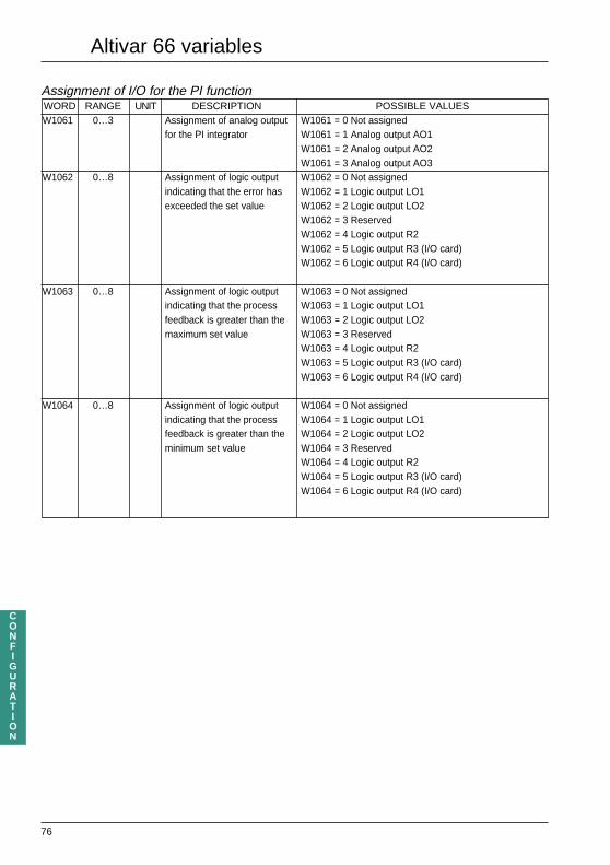
76
CONFIGURATION
Assignment of I/O for the PI functionWORD RANGE UNIT DESCRIPTION POSSIBLE VALUESW1061 0…3 Assignment of analog output W1061 = 0 Not assigned
for the PI integrator W1061 = 1 Analog output AO1W1061 = 2 Analog output AO2W1061 = 3 Analog output AO3
W1062 0…8 Assignment of logic output W1062 = 0 Not assignedindicating that the error has W1062 = 1 Logic output LO1exceeded the set value W1062 = 2 Logic output LO2
W1062 = 3 ReservedW1062 = 4 Logic output R2W1062 = 5 Logic output R3 (I/O card)W1062 = 6 Logic output R4 (I/O card)
W1063 0…8 Assignment of logic output W1063 = 0 Not assignedindicating that the process W1063 = 1 Logic output LO1feedback is greater than the W1063 = 2 Logic output LO2maximum set value W1063 = 3 Reserved
W1063 = 4 Logic output R2W1063 = 5 Logic output R3 (I/O card)W1063 = 6 Logic output R4 (I/O card)
W1064 0…8 Assignment of logic output W1064 = 0 Not assignedindicating that the process W1064 = 1 Logic output LO1feedback is greater than the W1064 = 2 Logic output LO2minimum set value W1064 = 3 Reserved
W1064 = 4 Logic output R2W1064 = 5 Logic output R3 (I/O card)W1064 = 6 Logic output R4 (I/O card)
Altivar 66 variables

77
CONFIGURATION
Multimotor and multiparameter functions
The use of multimotor and multiparameter functions can be dangerous (especially when switchingmotors); it is therefore advisable to read the instructions in the ATV66 user manual thoroughly.
To simplify this document, a list of multimotor and multiparameter functions and parameters is providedat the end of the manual (indicated by the letters M and P).
The multimotor function is used to configure up to three motors. These motors can be configured usingthe same data or independently. However, even though the functions or parameters are multimotor, theinputs and outputs of the speed controller are not. In fact, if the user decides to configure different I/O foreach motor, then only the last assignment will actually be taken into account.
Data structure
• The configuration of motor 1 is between words W206 and W324.• The configuration of motor 2 is between words W406 and W524 (same as motor 1 + 200).• The configuration of motor 3 is between words W606 and W724 (same as motor 1 + 400).
Example : W214, nominal current for motor 1.W414, nominal current for motor 2.W614, nominal current for motor 3.
The display variables monitor the motor which is currently running (word W2074 gives the parameter setor the number of the current motor).
Similarly, for the multiparameter function, the functions and parameters which can be accessed using thisfunction are indicated at the end of this manual (by the letter P).
Altivar 66 variables

78
CONFIGURATION
Configuration of multimotor and multiparameter functions WORD RANGE UNIT DESCRIPTION POSSIBLE VALUESW901 0…5 Configuration of multimotor = 0 1 motor
and multiparameter = 2 2 motorsfunctions = 3 2 parameter sets
= 4 3 motors= 5 3 parameter sets
Assignment of logic inputs for multimotor and multiparameter functions WORD RANGE UNIT DESCRIPTION POSSIBLE VALUESW902 0…8 Assignment of LIa (selecting W902 = 0 Not assigned (preset)
the set of parameters or W902 = 1 Reservedmotor) W902 = 2 Reserved
W902 = 3 Logic input LI3W902 = 4 Logic input LI4W902 = 5 Logic input LI5 (I/O card)W902 = 6 Logic input LI6 (I/O card)W902 = 7 Logic input LI7 (I/O card)W902 = 8 Logic input LI8 (I/O card)
W903 0…8 Assignment of LIb (selecting W903 = 0 Not assigned (preset)the set of parameters or W903 = 2 Reservedmotor) W903 = 3 Logic input LI3
W903 = 4 Logic input LI4W903 = 5 Logic input LI5 (I/O card)W903 = 6 Logic input LI6 (I/O card)W903 = 7 Logic input LI7 (I/O card)W903 = 8 Logic input LI8 (I/O card)
Altivar 66 variables

79
CONFIGURATION
PCMCIA memory card / ATV66 transfer - via line
A configuration that is saved on a PCMCIA memory card is called a page. A card consists of up to 16different configurations or pages.To transfer from the memory card to the ATV66 :–Initialize the transfer status register W2190 (optional). This places the transfer data in one of the followingstates : no card, card incompatible or ready to transfer.– Request a transfer from the memory card to the ATV66, or a transfer from the ATV66 to the memorycard W1700. The transfer is performed immediately. Consult the status register W2190 to confirm thetransfer has been successful.– Process the response obtained : if the reponse is NO, this means that there are insufficient access rights(motor running or semaphore configuration already reserved).
TransferWORD DESCRIPTION POSSIBLE VALUES
W1700 Selection of range to transfer W1700,0 to W1700,7 =
= 1 Page no. 1
= 2 Page no. 2
= 3 Page no. 3
= 4 Page no. 4
= 5 Page no. 5
= 6 Page no. 6
= 7 Page no. 7
= 8 Page no. 8
= 9 Page no. 9
= 10 Page no. 10
= 11 Page no. 11
= 12 Page no.12
= 13 Page no. 13
= 14 Page no. 14
= 15 Page no. 15
= 16 Page no. 16
Command to be used for the transfer W1700,8 to W1700,15 =
= 0 Word W2191 update : page identification
= 1 Reinitializion of the transfer status register : W2190
= 2 Request a transfer from the memory card to the
speed controller
= 3 Request a transfer from the speed controller to the
memory card
Altivar 66 variables

80
CONFIGURATION
PCMCIA memory card / ATV66 transfer - via line
Transfer status registerWORD DESCRIPTION POSSIBLE VALUES
W2190 Status of memory card/ ATV66 transfer W2190,0 to W2190,7 =
= 0 Ready to transfer
= 1 Transfert correct
= 2 No PCMCIA card present
= 3 PCMCIA card incompatible
= 4 Transfert incorrect (eg : page no. or transfer order
incorrect)
= 5 Transfer error (eg : write-protection by
PCMCIA card switch)
= 6 Page incompatible
= 7 Blank page
PCMCIA memory card removed W2190.8 = 1 card removed or changed
W2190.8 = 0 no card change
Page identificationWORD DESCRIPTION POSSIBLE VALUES
W2191 No. of selected page W2191,0 to W2191,7 =
= 1 Page no. 1
= 2 Page no. 2
= 3 Page no. 3
= 4 Page no. 4
= 5 Page no. 5
= 6 Page no. 6
= 7 Page no. 7
= 8 Page no. 8
= 9 Page no. 9
= 10 Page no. 10
= 11 Page no. 11
= 12 Page no.12
= 13 Page no. 13
= 14 Page no. 14
= 15 Page no. 15
= 16 Page no. 16
Blank page W2191,8, 8 = 1 blank page
W2191,8, 8 = 0 page not blank
Altivar 66 variables

81
CONFIGURATION
CONFIGURATION WORDS (read and write)Configuration of the intermediate parameters with I/O card
Configuration of voltage reductionWORD RANGE UNIT DESCRIPTION POSSIBLE VALUES
W310 Voltage reduction W310,0 = 0 Function not enabled (preset)
W310,0 = 1 Function enabled
W311 Choice of reduction type = 0 No reduction (preset)
= 1 Activation on frequency threshold
= 2 Activation via logic input
= 3 Level of analog input
W312 Voltage reduction via logic input = 0 No logic output assigned (preset)
= 1 Reserved
= 2 Reserved
= 3 Logic input LI3 on basic product
= 4 Logic input LI4 on basic product
= 5 Logic input LI5 (I/O card)
= 6 Logic input LI6 (I/O card)
= 7 Logic input LI7 (I/O card)
= 8 Logic input LI8 (I/O card)
W313 Voltage reduction via analog = 0 No logic output assigned (preset)
input = 1 Analog input AI1
= 2 Analog input AI2
= 3 Analog input AI3 (I/O card)
= 4 Analog input AI4 (I/O card)
W314* 0…Fmax VAR 0.1Hz Voltage reduction via frequency Preset at 60 Hz if 60 Hz supply
threshold Preset at 50 Hz if 50 Hz supply
W315 20...100 1% Voltage reduction coefficient Preset at 100%
* F max VAR : (W2204)
Constant torque : 400 Hz for Altivar 66 U41N4 to D79N4
Altivar 66 U41M2 to D46M2
200 Hz for Altivar 66 C10N4 to C31N4
Variable torque : 75/90 Hz (50 Hz/60Hz supply)
Altivar 66 variables

82
CONFIGURATION
Altivar 66 variablesCONFIGURATION WORDS (read and write)Configuration of the intermediate parameters with I/O card
Configuration of tachogenerator feedback WORD RANGE DESCRIPTION POSSIBLE VALUES
W870 Enabling of tachogenerator feedback W870,0 = 0 Function not enabled (preset)W870,0 = 1 Function enabled
W871 Assignment of speed feedback input = 0 No analog input (preset)= 3 Analog input AI3 (I/O card)
Configuration of orient WORD RANGE UNIT DESCRIPTION POSSIBLE VALUESW950 Enabling of orient W950,0 = 0 Function not enabled (preset)
W950,0 = 1 Function enabledW951 Assignment of logic input = 0 No logic input assigned (preset)
for command = 1 ReservedW952 Assignment of synchronization = 2 Reserved
logic input = 3 Logic input LI3 on basic product= 4 Logic input LI4 on basic product= 5 Logic input LI5 (I/O card)= 6 Logic input LI6 (I/O card)= 7 Logic input LI7 (I/O card)= 8 Logic input LI8 (I/O card)
W953 Orient : signalling logic output = 0 No logic output assigned (preset)to signal orient completed = 1 Logic output LO1
= 2 Logic output LO2= 3 Reserved= 4 Logic output R2= 5 Logic output R3 (I/O card)= 6 Logic output R4 (I/O card)
W954 0...100 0.1s Shutdown Preset at 1.0 sW955 50...150 1% Percentage of DC Preset at 70 %
injectionW956 0...301 0.1s DC injection time Preset at 2.0 s
Memorization of speed reference WORD RANGE UNIT DESCRIPTION POSSIBLE VALUESW850 Memorization of speed reference W850,0 = 0 Function not enabled (preset)
W850,0 = 1 Function enabledW851 Memorization of speed reference = 0 No logic input assigned (preset)
via logic input = 1 Reserved= 2 Reserved= 3 Logic input LI3 on basic product= 4 Logic input LI4 on basic product= 5 Logic input LI5 (I/O card)= 6 Logic input LI6 (I/O card)= 7 Logic input LI7 (I/O card)= 8 Logic input LI8 (I/O card)

83
CONFIGURATION
CONFIGURATION WORDS (read and write)Configuration of the intermediate parameters with I/O card
Configuration of cycle functionWORD RANGE DESCRIPTION POSSIBLE VALUES
W1000 Enabling of cycle function W1000,0 = 0 Function not enabled (preset)
W1000,0 = 1 Function enabled
Step 1 frequency sign W1000,8 = 0 Positive sign (preset)
W1000,8 = 1 Negative sign
Step 2 frequency sign W1000,9 = 0 Positive sign (preset)
W1000,9 = 1 Negative sign
Step 3 frequency sign W1000,10 = 0 Positive sign (preset)
W1000,10 = 1 Negative sign
Step 4 frequency sign W1000,11 = 0 Positive sign (preset)
W1000,11 = 1 Negative sign
Step 5 frequency sign W1000,12 = 0 Positive sign (preset)
W1000,12 = 1 Negative sign
Step 6 frequency sign W1000,13 = 0 Positive sign (preset)
W1000,13 = 1 Negative sign
Step 7 frequency sign W1000,14 = 0 Positive sign (preset)
W1000,14 = 1 Negative sign
Step 8 frequency sign W1000,15 = 0 Positive sign (preset)
W1000,15 = 1 Negative sign
W1001 Logic input for = 0 No logic input assigned
cycle start = 1 Reserved
W1002 Logic input for = 2 Reserved
cycle reset = 3 Logic input LI3 on basic product
W1003 Logic input for = 4 Logic input LI4 on basic product
cycle pause = 5 Logic input LI5 (I/O card)
W1004 Logic input for = 6 Logic input LI6 (I/O card)
change to next step = 7 Logic input LI7 (I/O card)
= 8 Logic input LI8 (I/O card)
W1005 Logic output for = 0 No logic input assigned
cycle over = 1 Logic output LO1
W1006 Logic output for = 2 Logic output LO2
cycle fault = 3 Reserved
= 4 Logic output R2
= 5 Logic output R3 (I/O card)
= 6 Logic output R4 (I/O card)
Altivar 66 variables

84
CONFIGURATION
Altivar 66 variablesCONFIGURATION WORDS (read and write)Configuration of the intermediate parameters with I/O card
Configuration of cycle function (continued) WORD RANGE UNIT DESCRIPTION PRESET
W1007 0...250 Step 1 number of sub-cycles 0
W1008 0...250 Step 2 number of sub-cycles 0
W1009 0...250 Step 3 number of sub-cycles 0
W1010 0...250 Step 4 number of sub-cycles 0
W1011 0...250 Step 5 number of sub-cycles 0
W1012 0...250 Step 6 number of sub-cycles 0
W1013 0...250 Step 7 number of sub-cycles 0
W1014 0...250 Step 8 number of sub-cycles 0
W1015 0...Fmax VAR 0.1Hz Step 1 Frequency 30.0 Hz
W1016 1...9999 0.1s Step 1 Ramp time 3.0 s
W1017 0...6000 1s Step 1 Step duration 30 s
W1018 0...Fmax VAR 0.1Hz Step 2 Frequency 30.0 Hz
W1019 1...9999 0.1s Step 2 Ramp time 3.0 s
W1020 0...6000 1s Step 2 Step duration 0 s
W1021 0...Fmax VAR 0.1Hz Step 3 Frequency 30.0 Hz
W1022 1...9999 0.1s Step 3 Ramp time 3,0 s
W1023 0...6000 1s Step 3 Step duration 0 s
W1024 0...Fmax VAR 0.1Hz Step 4 Frequency 30.0 Hz
W1025 1...999 0.1s Step 4 Ramp time 3,0 s
W1026 0...6000 1s Step 4 Step duration 0 s
W1027 0...Fmax VAR 0.1Hz Step 5 Frequency 30.0 Hz
W1028 1...999 0.1s Step 5 Ramp time 3.0 s
W1029 0...6000 1s Step 5 Step duration 0 s
W1030 0...Fmax VAR 0.1Hz Step 6 Frequency 30.0 Hz
W1031 1...999 0.1s Step 6 Ramp time 3.0 s
W1032 0...6000 1s Step 6 Step duration 0 s
W1033 0...Fmax VAR 0.1Hz Step 7 Frequency 30.0 Hz
W1034 1...999 0.1s Step 7 Ramp time .0 s
W1035 0...6000 1s Step 7 Step duration 0 s
W1036 0...Fmax VAR 0.1Hz Step 8 Frequency 30.0 Hz
W1037 1...999 0.1s Step 8 Ramp time 3.0 s
W1038 0...6000 1s Step 8 Step duration 0 s
F max VAR :
Constant torque : 400 Hz for Altivar 66 U41N4 to D79N4
Altivar 66 U41M2 to D46M2
200 Hz for Altivar 66 C10N4 to C31N4
Variable torque : 75/90 Hz (50 Hz/60Hz supply)
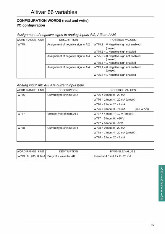
85
CONFIGURATION
Altivar 66 variablesCONFIGURATION WORDS (read and write)I/O configuration
Assignment of negative signs to analog inputs AI2, AI3 and AI4WORD RANGE UNIT DESCRIPTION POSSIBLE VALUES
W775 Assignment of negative sign to AI2 W775,2 = 0 Negative sign not enabled(preset)
W775,2 = 1 Negative sign enabled
Assignment of negative sign to AI4 W775,3 = 0 Negative sign not enabled(preset)
W775,3 = 1 Negative sign enabled
Assignment of negative sign to AI4 W775,4 = 0 Negative sign not enabled(preset)
W775,4 = 1 Negative sign enabled
Analog input AI2 AI3 AI4 current input typeWORD RANGE UNIT DESCRIPTION POSSIBLE VALUES
W776 Current type of input AI 2 W776 = 0 Input 0 - 20 mA
W776 = 1 Input 4 - 20 mA (preset)
W776 = 2 Input 20 - 4 mA
W776 = 3 Input X - 20 mA (see W779)
W777 Voltage type of input AI 3 W777 = 4 Input +/- 10 V (preset)
W777 = 5 Input 0 / +10 V
W777 = 6 Input 0 / -10V
W778 Current type of input AI 4 W778 = 0 Input 0 - 20 mA
W778 = 1 Input 4 - 20 mA (preset)
W778 = 2 Input 20 - 4 mA
WORD RANGE UNIT DESCRIPTION POSSIBLE VALUES
W779 0...200 0.1mA Entry of a value for AI2 Preset at 4.0 mA for X - 20 mA

86
CONFIGURATION
Altivar 66 variablesCONFIGURATION WORDS (read and write)I/O configurationWORD RANGE UNIT DESCRIPTION POSSIBLE VALUESW780 Type of signal of analog output AO1 = 0 Output 0 - 20 mA (preset)
= 1 Output 4 - 20 mAW781 Type of signal of analog output AO2 = 0 Output 0 - 20 mA (preset)
= 1 Output 4 - 20 mAW782 Type of signal of analog output AO3 = 0 Output 0 - 20 mA (preset)
= 1 Output 4 - 20 mA
WORD RANGE UNIT DESCRIPTION POSSIBLE VALUESW783 Assignment of analog output AO1 = 0 Not assigned
= 1 Motor current= 2 Motor frequency(preset)= 3 Motor power= 4 Motor torque= 5 Motor voltage= 6 Motor thermal state= 7 Ramp output= 8 PI set point= 9 Sensor feedback= 10 PI error= 11 PI error integrator
W784 Assignment of analog output AO2 = 0 Not assigned= 1 Motor current (preset)= 2 Motor frequency= 3 Motor power= 4 Motor torque= 5 Motor voltage= 6 Motor thermal state= 7 Ramp output= 8 PI set point= 9 Sensor feedback= 10 PI error= 11 PI error integrator
W785 Assignment of analog output AO3 = 0 Not assigned (preset)= 1 Motor current= 2 Motor frequency= 3 Motor power (preset with I/O card)= 4 Motor torque= 5 Motor voltage= 6 Motor thermal state= 7 Ramp output= 8 PI set point= 9 Sensor feedback= 10 PI error= 11 PI error integrator
W786 0...Fmax VAR 0.1Hz Logic output activation frequency level 1 Preset at 25.0 HzW787 0...Fmax VAR 0.1Hz Logic output activation frequency level 2 Preset at 0.0 HzW788 10...150 1% Logic output activation current level 1 Preset at 100%W789 10...150 1% Logic output activation current level 2 Preset at 50%W790 0...200 1% Logic output activation thermal state 1 Preset at 100%W791 0...200 1% Logic output activation thermal state 2 Preset at 10%W792 0...100 1% Logic output activation torque level Preset at 100%
F max VAR :Constant torque : 400 Hz forAltivar 66 U41N4 to D79N4
Altivar 66 U41M2 to D46M2200 Hz for Altivar 66 C10N4 to C31N4
Variable torque : 75/90 Hz (50 Hz/60Hz supply)

87
CONFIGURATION
CONFIGURATION WORDS (read and write)I/O configuration
WORD DESCRIPTION POSSIBLE VALUES
W793 Assignment of logic output LO1 = 0 Not assigned
W794 Assignment of logic output LO2 = 1 Speed controller ready
W798 Assignment of logic output R2 = 2 Speed controller running
W799 Assignment of logic output R3 = 3 Set point reached
W800 Assignment of logic output R4 = 4 Forward operation
= 5 Reverse operation
= 6 Keypad control
= 7 Auto/Man automatic position
= 8 Current limit
= 9 Torque limit
= 10 Fault
= 11 Speed controller thermal alarm
= 12 Loss of AI2
= 13 No ramp follow (with I/O card)
= 14 Tachogenerator feedback fault (with I/O card)
= 15 Overspeed (with I/O card)
= 16 Frequency threshold 1 reached
= 17 Frequency threshold 2 reached (with I/O card)
= 18 Current threshold 1 reached
= 19 Current threshold 2 reached (with I/O card)
= 20 Thermal state threshold 1 reached
= 21 Thermal state threshold 2 reached (with I/O card)
= 22 Reserved
= 23 Brake release
= 24 Shutdown
= 25 Orient complete
= 26 Cycle complete
= 27 Cycle fault
= 28 Bypass command
= 29 JOG
= 30 Reserved
= 31 Reserved
= 32 PI error exceeded
= 33 (PI) max error exceeded
= 34 (PI) min error exceeded
Altivar 66 variables

88
CONFIGURATION
Altivar 66 variables
CONFIGURATION WORDS (read and write)Configuration of the keypad
WORD DESCRIPTION POSSIBLE VALUES
W740 Assignment of F1 key = 0 Not assigned
(preset) = 1 Direction of rotation
= 2 JOG
= 3 Reserved
= 4 Fault reset
= 5 Scrolling of bargraph
= 6 Preset speed 1
= 7 Preset speed 2
= 8 Start cycle function
= 9 Cycle function : change to next cycle
= 10 Cycle function : cycle reset
= 11 Local control
WORD DESCRIPTION POSSIBLE VALUES
W741 Assignment of a logic input to F2 key = 0 Not assigned
= 1 Direction of rotation
= 2 JOG
= 3 Terminal block/keypad switching
= 4 Reset fault
(preset) = 5 Scrolling of bargraph
= 6 Preset speed 1
= 7 Preset speed 2
= 8 Start cycle function
= 9 Cycle function : change to next cycle
= 10 Cycle function : cycle reset
= 11 Reserved
WORD DESCRIPTION POSSIBLE VALUES
W742 Assignment of a logic input to F3 key = 0 Not assigned
= 1 Direction of rotation
(preset) = 2 JOG
= 3 Reserved
= 4 Fault reset
= 5 Scrolling of bargraph
= 6 Preset speed 1
= 7 Preset speed 2
= 8 Start cycle function
= 9 Cycle function : change to next cycle
= 10 Cycle function : cycle reset
= 11 Reserved

89
CONFIGURATION
Altivar 66 variables
CONFIGURATION WORDS (read and write)Configuration of the keypad
WORD RANGE UNIT DESCRIPTION POSSIBLE VALUES
W743 Terminal block / keypad = 0 Control via terminal block (preset)
control = 1 Control via keypad
= 2 Switching via logic input
= 3 Switching via F2 key
W744 Logic input for Terminal block/ = 0 No logic input assigned
Graphic keypad switching (preset)
= 1 Reserved
= 2 Reserved
= 3 Logic input LI3 on basic product
= 4 Logic input LI4 on basic product
= 5 Logic input LI5 (I/O card)
= 6 Logic input LI6 (I/O card)
= 7 Logic input LI7 (I/O card)
= 8 Logic input LI8 (I/O card)
W745 0...Fmax VAR 0.1Hz Keypad preset speed 1 Preset at 0.0 Hz
W746 0...Fmax VAR 0.1Hz Keypad preset speed 2 Preset at 0.0 Hz
W747 2...100 0.1Hz JOG frequency Preset at 5.0 Hz
W747 and W893 = same word

90
CONFIGURATION
CONFIGURATION WORDS (read and write)Configuration of faults
Fault configuration registerWORD DESCRIPTION POSSIBLE VALUES
W755 Automatic restart W755,1 = 0 Not enabled (preset)
W755,1 = 1 Enabled
Enabling of power loss function W755,2 = 0 Not enabled (preset)
W755,2 = 1 Enabled
Enabling of input phase failure function W755,3 = 0 Not enabled
W755,3 = 1 Enabled (preset)
Enabling of motor phase fault function W755,4 = 0 Not enabled
W755,4 = 1 Enabled (preset)
Enabling of DB resistor protection W755,5 = 0 Not enabled (preset)
W755,5 = 1 Enabled
Check presence of braking resistor W755,6 = 0 Not enabled (preset)
W755,6 = 1 Enabled
Enabling of speed controller reset W755,7 = 0 Not enabled (preset)
W755,7 = 1 Enabled
External fault W755,8 = 0 Not enabled (preset)
W755,8 = 1 Enabled
Logic input active state (0 or 1) W755,9 = 0 Active at low state
W755,9 = 1 Active at high state
Current adaptation (variable torque) W755,10 = 0 Not enabled (preset)
W755,10 = 1 Enabled
Enabling of flying restart function W755,11 = 0 Not enabled
W755,11 = 1 Enabled (preset)
Enabling of loss follower W755,12 = 0 Not enabled (preset)
W755,12 = 1 Enabled
Enabling of thermal protection W755,13 = 0 Not enabled
W755,13 = 1 Enabled (preset)
Altivar 66 variables

91
CONFIGURATION
CONFIGURATION WORDS (read and write)Configuration of faults
WORD RANGE UNIT DESCRIPTION POSSIBLE VALUES
W756 Stopping methods on a fault = 0 Normal stop
= 1 Fast stop
= 2 Freewheel stop (preset)
Configuration of automatic restartWORD RANGE UNIT DESCRIPTION COMMENT
W757 1...5 Number of possible restarts Preset at 5
W758 1...600 1s Locking time Preset at 30 s
Type of motor overloadWORD RANGE UNIT DESCRIPTION POSSIBLE VALUES
W759 0...3 Type of motor overload = 0 No protection
= 1 Motor self-cooled
= 2 Motor force-cooled
= 3 Manual tuning of motor minimum
speed at full load
(preset at 50%) W761
W760 45%..115% 0.1A Thermal tripping current Factory preset at 0.9 times speed controller
of W214 nominal current
W761 0…100 1% Minimum speed at full load Preset at 50%
W762 0…100 1% Maximum current at zero frequency Preset at 50%
W763 0.1Ω Value of braking resistor
W764 1W Power of braking resistor
WORD RANGE UNIT DESCRIPTION COMMENT
W765 Reset speed controller via = 0 No logic input assigned
logic input = 1 Reserved
W766 External fault : activation logic = 2 Reserved
input = 3 Logic input LI3
= 4 Logic input LI4
= 5 Logic input LI5 (I/O card)
= 6 Logic input LI6 (I/O card)
= 7 Logic input LI7 (I/O card)
= 8 Logic input LI8 (I/O card)
Altivar 66 variables

92
CONFIGURATION
Altivar 66 variablesCONFIGURATION WORDS (read and write)Configuration of faults
Loss followerWORD RANGE UNIT DESCRIPTION POSSIBLE VALUES
W767 0...Fmax VAR 0.1 Hz Frequency set point if Programming of a reference speed
loss follower occurs (preset at 0 Hz)
W768 Type of action in the event of = 0 No detection (preset)
loss of current input : = 1 Skip to frequency
= 2 Change to fault mode
Type of flying restartWORD RANGE UNIT DESCRIPTION POSSIBLE VALUES
W769 Type of flying restart = 0 On ramp (preset)
= 1 Current limit
= 2 No restart
F max VAR :
Constant torque : 400 Hz for Altivar 66 U41N4 to D79N4
Altivar 66 U41M2 to D46M2
200 Hz for Altivar 66 C10N4 to C31N4
Variable torque : 75/90 Hz (50 Hz/60Hz supply)

93
CONFIGURATION
Altivar 66 variablesCONFIGURATION WORDS (read and write)Configuration of the keypad display
WORD DESCRIPTION POSSIBLE VALUES
W730 Configuration of graphics = 0 One bargraph (preset)
= 1 Two bargraphs
= 2 Four parameters
W731 Configuration of bargraph 1 = 0 Set point frequency (preset)
W732 Configuration of bargraph 2 = 1 Output frequency
= 2 Output current
= 3 Motor torque
= 4 Output power
= 5 Output voltage
= 6 Supply voltage
= 7 Bus voltage
= 8 Motor thermal state
= 9 Speed controller thermal state
= 10 Motor speed
= 11 Machine set point (user unit)
= 12 Machine speed (user unit)
= 15 PI feedback
= 16 PI set point
WORD RANGE UNIT DESCRIPTION
W734 1...100 Scale factor of machine units
*The machine units of the set point and machine speed variables are entered via the graphic keypad
(see "display configuration" in the programming manual)
WORD DESCRIPTION POSSIBLE VALUES
W749 Language = 1 German
= 2 English
= 3 Spanish
= 4 French
= 5 Italian
= 6 Reserved
= 7 Swedish

94
ADDRESS ZONE COMMON TO ALTIVAR 66 AND ALTIVAR 45 2
Command bits (read and write) of words W0 and W1BIT NAME DESCRIPTION NOTES
B0 TST De-energization of speed controller safety relay Always read at 0
B1 RST Speed controller reset (active on transition
B2 CLO Assignment of commands in LOCAL mode from 0 to 1)
B3 CLI Assignment of commands in LINE mode
B4 NTO Inhibition of communication check
B5 RUN Start/stop command
B6 REV Reverse direction of rotation = change frequency set point sign
B7 DCB Braking control
B8 CAL Selection of freewheel stop
B9 CAR Selection of fast stop
B10 RTM Motor voltage reduction
Adjustment words (read and write)WD NAME RANGE RANGE UNITS DESCRIPTION COMMENTS
ATV45.2 ATV66
W2 CGL 0..5 0..100 0.1 Hz Slip compensation
W4 RLI 5..150% 50...1360 0.10% Reduction of current
limit
W6 IBR 0.2..1.5 In 50...150 (%) 0.1 A Braking current amplitude
W7 IAR 0.2..1.5 In 50...150 (%) 0.1 A DC amplitude when
stopping
W8 TAR 0.5..4 s 0...301 0.1 s DC injection time when
stopping
W9 UFR 0..100 0..100 1 Voltage/frequency ratio Adjustment word : Voltage
adjustment coefficient Boost
W10 ITH 0.45..1.05 In 50...115 0.1 A Motor thermal protection
W11 GBF 0..100 0..100 0.1 Frequency loop gain
W12 FR1 0.. HSP 0.. HSP 0.1 Hz Skip frequency 1
W13 FR2 0.. HSP 0.. HSP 0.1 Hz Skip frequency 2
W14 LSP 0.. HSP 0.. HSP 0.1 Hz Minimum frequency
W15 HSP LSP..f max LSP..f max 0.1 Hz Maximum frequency
W16 ACC 0.2.. 990 s 1...9999 0.1 s Acceleration time
W17 DEC 0.2.. 990 s 1...9999 0.1 s Deceleration time
Altivar 66 variables

95
ADDRESS ZONE COMMON TO ALTIVAR 66 AND ALTIVAR 45 2
Command registerWORDS NAME RANGE RANGE UNITS DESCRIPTION
ATV66 ATV 45.2
W18 COM – – Command register
– W18,0 Speed controller reset
DLI W18,1 Assignment of logic commands in LINE mode
FLI W18,2 Assignment of set points in LINE mode
W18,3 Reserved
NTO W18,4 Inhibit communication check
RUN W18,5 Stop/Start command
DCB W18,6 DC injection braking control
– W18,7 Reserved
CAL W18,8 Selection of freewheel stop
CAR W18,9 Selection of fast stop
RTM W18,10 Motor voltage reduction control
– W18,11 Reserved
– W18,12 Reserved
– W18,13 Reserved
– W18,14 Reserved
– W18,15 Storage in EEPROM
W19 FRH LSP .. 0.1 Hz Frequency set point
HSP
Altivar 66 variables

96
Altivar 66 variables
ADDRESS ZONE COMMON TO ALTIVAR 66 AND ALTIVAR 45 2
Configuration words (read and write)WORDSNAME RANGE RANGE UNITS DESCRIPTION
ATV45.2 ATV66W53 0.2.. 990 s 1...9999 0.1 s Acceleration time 2
W54 0.2.. 990 s 1...9999 0.1 s Deceleration time 2
W61 W62.. 10Hz 0...LSP 0.1 Hz Brake application level
W62 0 Hz .. W61 0...LSP 0.1 Hz Brake release level
W63 0.. 4 s 0...50 0.1 s Brake application time
REGISTER OF PAST FAULTS (read only)
Configuration words (read only)WORDSNAME RANGE RANGE UNITS DESCRIPTION
ATV45.2 ATV66W120 Register of 1st past fault
W121 Register of 2nd past fault
W121 Register of 3rd past fault
W121 Register of 4th past fault
W121 Register of 5th past fault
W121 Register of 6th past fault
W121 Register of 7th past fault
W127 Register of 8th past fault
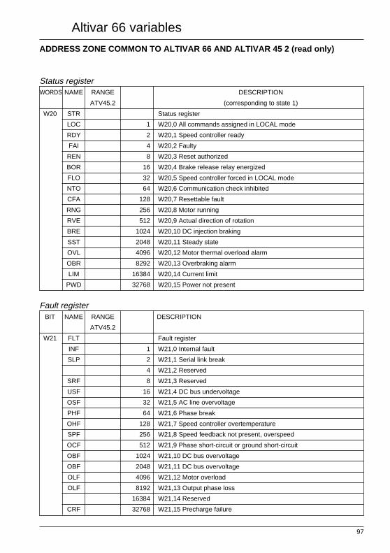
97
Altivar 66 variables
ADDRESS ZONE COMMON TO ALTIVAR 66 AND ALTIVAR 45 2 (read only)
Status registerWORDS NAME RANGE DESCRIPTION
ATV45.2 (corresponding to state 1)
W20 STR Status register
LOC 1 W20,0 All commands assigned in LOCAL mode
RDY 2 W20,1 Speed controller ready
FAI 4 W20,2 Faulty
REN 8 W20,3 Reset authorized
BOR 16 W20,4 Brake release relay energized
FLO 32 W20,5 Speed controller forced in LOCAL mode
NTO 64 W20,6 Communication check inhibited
CFA 128 W20,7 Resettable fault
RNG 256 W20,8 Motor running
RVE 512 W20,9 Actual direction of rotation
BRE 1024 W20,10 DC injection braking
SST 2048 W20,11 Steady state
OVL 4096 W20,12 Motor thermal overload alarm
OBR 8292 W20,13 Overbraking alarm
LIM 16384 W20,14 Current limit
PWD 32768 W20,15 Power not present
Fault registerBIT NAME RANGE DESCRIPTION
ATV45.2
W21 FLT Fault register
INF 1 W21,0 Internal fault
SLP 2 W21,1 Serial link break
4 W21,2 Reserved
SRF 8 W21,3 Reserved
USF 16 W21,4 DC bus undervoltage
OSF 32 W21,5 AC line overvoltage
PHF 64 W21,6 Phase break
OHF 128 W21,7 Speed controller overtemperature
SPF 256 W21,8 Speed feedback not present, overspeed
OCF 512 W21,9 Phase short-circuit or ground short-circuit
OBF 1024 W21,10 DC bus overvoltage
OBF 2048 W21,11 DC bus overvoltage
OLF 4096 W21,12 Motor overload
OLF 8192 W21,13 Output phase loss
16384 W21,14 Reserved
CRF 32768 W21,15 Precharge failure

98
Altivar 66 variables
ADDRESS ZONE COMMON TO ALTIVAR 66 AND ALTIVAR 45 2
Signalling words (read only)WORDS NAME RANGE RANGE UNIT DESCRIPTION
ATV45.2 ATV66
W22 LCR 0.1 A Motor current
W23 RFR 0.1 Hz Rotation frequency
W24 THR 0.10% Motor thermal state
W25 ULN 0.1 V AC supply voltage
W26 CHM 0.10% Motor load
W27 – – Reserved
W28 – – Reserved
W30 DAI 0.. 1000 0...100 Value of speed controller analog input
W31 – – Reserved
W32 – – Reserved

99
Start End Description Page
address address
W198 Configuration semaphore 61
W199 Speed controller locked when stopped 61
W200 2- or 3- wire control 63
W201 Torque type 63
W202 Motor power 63
W206 Control type M * 63
W210 Direction of phase rotation M 63
W211 Motor nominal frequency type M 62
W212 Motor nominal frequency M 62
W213 Motor nominal voltage M 62
W214 Motor nominal current M 62
W215 Torque limit in generator phase M 63
W216 Torque limit in motor phase M 63
W219 Motor nominal speed configuration M 62
W225 W227 Slip compensation value M 64
W226 Slip compensation type M 64
W227 Slip compensation value M 64
W228 IR compensation value M 64
W229 Profile M 64
W230 Voltage boost M 64
W231 Damping M 64
W232 Bandwidth 64
W245 W253 Enabling of braking sequence M 65
W246 Brake control logic output 65
W247 Brake release frequency M 65
W248 Brake dwell current threshold M 65
W249 Brake dwell time M 65
W250 Brake release frequency M 65
W251 Brake release time M 65
W252 DC injection threshold M 65
W253 DC injection time M 65
W260 W265 Enabling of current limit M 66
W261 Current limit type M 66
W262 Logic input to activate current limit 66
W263 Analog input for current limit 66
W264 Activation frequency level M 66
W265 Limit current M 66
W270 W283 Enabling of ramp switching M,P 67
* High torque available on motor 1 only - M = Multimotor - P = Multiparameter
INDEX

100
INDEX
Start End Description Page
address address
W271 Acceleration type M,P 67
W272 Rounding coefficient for S acceleration ramps M,P 67
W273 Rounding coefficient for U acceleration ramps M,P 67
W274 Deceleration type M,P 67
W275 Rounding coefficient for S deceleration ramps M,P 67
W276 Rounding coefficient for U deceleration ramps M,P 67
W277 Ramp switching type M,P 67
W278 Logic input for ramp switching 67
W279 Activation frequency level M,P 67
W280 Duration of first acceleration ramp M,P 67
W281 Duration of first deceleration ramp M,P 67
W282 Duration of second acceleration ramp M,P 67
W283 Duration of second deceleration ramp M,P 67
W290 Skip frequency range 1 M,P 67
Skip frequency range 2 67
Skip frequency range 3 67
W291 Skip frequency value 1 M,P 67
W292 Skip frequency value 2 M,P 67
W293 Skip frequency value 3 M,P 67
W301 Motor maximum frequency M,P 62
W302 High speed M,P 62
W303 Low speed M,P 62
W310 W315 Voltage reduction M,P 81
W311 Choice of reduction type M,P 81
W312 Voltage reduction via logic input 81
W313 Voltage reduction via analog input 81
W314 Voltage reduction via frequency level M,P 81
W315 Voltage reduction coefficient M,P 81
W320 Torque limit type M 63
W321 Assignment of torque limit activating logic input 63
W322 Assignment of torque limit activating analog input 63
W323 Torque limit in generator phase M 63
W324 Torque limit in motor phase M 63
W730 Configuration of graphics 93
W731 Configuration of bargraph 1 93
W732 Configuration of bargraph 2 93
W734 Scale factor of machine units 93
W740 Assignment of F1 key 88
M = Multimotor - P = Multiparameter

101
INDEX
Start End Description Page
address address
W741 Assignment of a logic input to F2 key 88
W742 Assignment of a logic input to F3 key 88
W743 Terminal block / keypad control 89
W744 Logic input for Terminal block / keypad switching 89
W745 Keypad preset speed 1 89
W746 Keypad preset speed 2 89
W747 JOG 89
W748 Type of access to speed controller data via keypad 61
W749 Language 93
W755 Automatic restart 90
Enabling of power loss function 90
Enabling of input phase failure function 90
Enabling of motor phase fault fuction 90
Enabling of DB resistor protection 90
Check presence of braking resistor 90
Enabling of speed controller reset 90
External fault 90
Logic input active state (0 or 1) 90
Current adaptation (Variable torque) 90
Enabling of flying restart function 90
Enabling of loss follower 90
Enabling of thermal protection 90
W756 Stopping methods on a fault 91
W757 Number of possible restarts 91
W758 Locking time 91
W759 Type of motor overload 91
W760 Thermal tripping current 91
W761 Minimum speed at full load 91
W762 Maximum speed at zero frequency 91
W763 Value of braking resistor 91
W764 Power of braking resistor 91
W765 Reset speed controller via logic input 91
W766 External fault : activation logic input 91
W767 Frequency set point if loss follower occurs 92
W768 Type of action in the event of loss of current input 92
W769 Type of flying restart 92
W775 Assignment of negative sign to AI2 85
Assignment of negative sign to AI3 85

102
INDEX
Start End Description Page
address address
Assignment of negative sign to AI4 85
W776 Current type of input AI2 85
W777 Voltage type of input AI3 85
W778 Current type of input AI4 85
W779 Entry of a value for AI2 85
W780 Type of signal of analog output AO1 86
W781 Type of signal of analog output AO2 86
W782 Type of signal of analog output AO3 86
W783 Assignment of analog output AO1 86
W784 Assignment of analog output AO2 86
W785 Assignment of analog output AO3 86
W786 Logic output activation frequency level 1 86
W787 Logic output activation frequency level 2 86
W788 Logic output activation current level 1 86
W789 Logic output activation current level 2 86
W790 Logic output activation thermal state 1 86
W791 Logic output activation thermal state 1 86
W792 Logic output activation torque level 86
W793 Assignment of logic output LO1 87
W794 Assignment of logic output LO2 87
W798 Assignment of logic output R2 87
W799 Assignment of logic output R3 87
W800 Assignment of logic output R4 87
W810 W813 Limitation to 0 of the summing of analog inputs 65
assigned to the frequency set point
W811 Analog input : frequency set point «a» 65
W812 Analog input : frequency set point «b» 65
W813 Analog input : frequency set point «c» 65
W820 W823 Enabling of + speed / - speed function 69
W821 Type of +/ - speed 69
W822 Logic input for - speed 69
W823 Logic input for + speed 69
W830 W841 Enabling of preset speeds 70
W831 Choice of number of preset speeds 70
W832 Select via logic input (a) 70
W833 Select via logic input (b) 70
W834 Select via logic input (c) 70
W835 Speed 1 value 70

103
INDEX
Start End Description Page
address address
W836 Speed 2 value 70
W837 Speed 3 value 70
W838 Speed 4 value 70
W839 Speed 5 value 70
W840 Speed 6 value 70
W841 Speed 7 value 70
W850 W851 Memorization of speed reference 82
W851 Memorization of speed reference via logic input 82
W860 W862 Auto/Man 71
W861 Switching auto / manual logic input 71
W862 Auto / Run logic input 71
W870 Enabling of tachogenerator feedback 82
W871 Assignment of speed feedback input 82
W880 W881 Enabling of reverse function 68
W881 W894 Logic input for enabling Run / Reverse 68
W890 Enabling of JOG function 68
W891 Logic input for JOG activation 68
W892 Logic output for signalling enabling of JOG 68
W893 JOG reference frequency 68
W894 Dead time between two JOG pulses 68
W901 Configuration of multimotor and multiparameter functions 78
W902 Assignment of LIa (selecting the set of parameters or motors) 78
W903 Assignment of LIb (selecting the set of parameters or motors) 78
W910 W911 Enabling of local forcing 71
W911 Local forcing via logic input 71
W920 W927 Enabling of controlled stop 72
Activation input active level 72
W921 Controlled stop : type of input activation 72
W922 Stop command via logic input 72
W923 Type of controlled stop activated via logic input 72
W924 Type of controlled stop activated via frequency level 72
W925 Frequency level adjustment 72
W926 Percentage of DC current injected 72
W927 Adjustment of DC current injection time 72
W940 W942 Shutdown 73
W941 Logic output signalling shutdown completed 73
W942 Low speed dwell time 73
W950 W956 Enabling of orient 82
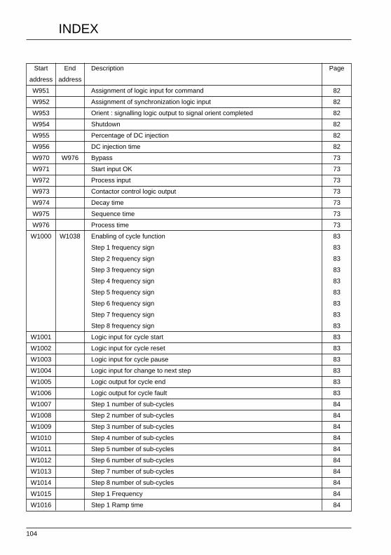
104
INDEX
Start End Description Page
address address
W951 Assignment of logic input for command 82
W952 Assignment of synchronization logic input 82
W953 Orient : signalling logic output to signal orient completed 82
W954 Shutdown 82
W955 Percentage of DC injection 82
W956 DC injection time 82
W970 W976 Bypass 73
W971 Start input OK 73
W972 Process input 73
W973 Contactor control logic output 73
W974 Decay time 73
W975 Sequence time 73
W976 Process time 73
W1000 W1038 Enabling of cycle function 83
Step 1 frequency sign 83
Step 2 frequency sign 83
Step 3 frequency sign 83
Step 4 frequency sign 83
Step 5 frequency sign 83
Step 6 frequency sign 83
Step 7 frequency sign 83
Step 8 frequency sign 83
W1001 Logic input for cycle start 83
W1002 Logic input for cycle reset 83
W1003 Logic input for cycle pause 83
W1004 Logic input for change to next step 83
W1005 Logic output for cycle end 83
W1006 Logic output for cycle fault 83
W1007 Step 1 number of sub-cycles 84
W1008 Step 2 number of sub-cycles 84
W1009 Step 3 number of sub-cycles 84
W1010 Step 4 number of sub-cycles 84
W1011 Step 5 number of sub-cycles 84
W1012 Step 6 number of sub-cycles 84
W1013 Step 7 number of sub-cycles 84
W1014 Step 8 number of sub-cycles 84
W1015 Step 1 Frequency 84
W1016 Step 1 Ramp time 84

105
INDEX
Start End Description Page
address address
W1017 Step 1 Step duration 84
W1018 Step 2 Frequency 84
W1019 Step 2 Ramp time 84
W1020 Step 2 Step duration 84
W1021 Step 3 Frequency 84
W1022 Step 3 Ramp time 84
W1023 Step 3 Step duration 84
W1024 Step 4 Frequency 84
W1025 Step 4 Ramp time 84
W1026 Step 4 Step duration 84
W1027 Step 5 Frequency 84
W1028 Step 5 Ramp time 84
W1029 Step 5 Step duration 84
W1030 Step 6 Frequency 84
W1031 Step 6 Ramp time 84
W1032 Step 6 Step duration 84
W1033 Step 7 Frequency 84
W1034 Step 7 Ramp time 84
W1035 Step 7 Step duration 84
W1036 Step 8 Frequency 84
W1037 Step 8 Ramp time 84
W1038 Step 8 Step duration 84
W1040 Enabling of PI function 74W1041 Authorizing the direction of rotation 74
Increase in the PI error 74PI set point value by the terminal 74Man. set point by the terminal 74
W1042 Assignment of analog input for the PI set point 75W1043 Gain 74W1044 Offset 74W1045 Assignment of analog input for the sensor feedback 75W1046 Min. feedback value for the sensor in user-defined units 74W1047 Max. feedback value for the sensor in user-defined units 74W1048 Minimum value for triggering the alarm 74W1049 Maximum value for triggering the alarm 74W1050 Assignment of analog input for the speed reference 75W1051 Assignment of logic input for switching between man/auto mode 75W1052 Assignment of logic input for reversing the direction of rotation 75W1053 PI error ratio 74W1054 PI set point value for the graphic keypad 74W1055 Speed reference value for the graphic keypad 74

106
INDEX
Start End Description Page
address address
W1056 Proportional gain 74W1057 Integral gain 74W1058 Assignment of analog output for the PI set point 75W1059 Assignment of analog output for the PI feedback 75W1060 Assignment of analog output for the PI error 75W1061 Assignment of analog output for the PI integrator 76W1062 Assignment of logic output indicating that the error has exceeded the set value 76W1063 Assignment of logic output indicating that the process feedback
is greater than the maximum set value 76W1064 Assignment of logic output indicating that the process feedback
is greater than the minimum set value 76W1700 Selection of range to transfer 79
Command to be used for the transfer 79W1993 Proportional gain 44W1994 Integral gain 44W1995 Gain 44W1996 Offset 44W1997 Fault ratio 44W1998 Terminal PI set point value 44W1999 Terminal speed reference value 44
W2000 High speed 44
W2001 Low speed 44
W2002 1st acceleration ramp time 44
W2003 1st deceleration ramp time 44
W2004 2nd acceleration ramp time 44
W2005 2nd deceleration ramp time 44
W2006 Slip compensation : motor value 44
W2007 IR compensation 44
W2008 Profile 44
W2009 BOOST voltage 44
W2010 Damping 44
W2011 Bandwidth 44
W2012 Thermal protection 44
W2020 Speed controller reset 45
Assignment of logic commands on line (DLI) 45
Assignment of references on line (FLI) 45
Ramp 2 command 45
Communication check inhibited (NTO) 45
Start/Stop command (RUN) 45
DC injection braking command (DCB) 45
Select orient stop 45

107
INDEX
Start End Description Page
address address
Select freewheel stop 45
Select fast stop 45
Voltage reduction command 45
Select motor a 45
Select motor b 45
External fault command (EFL) 45
W2021 Frequency set point on line 46
W2022 State of logic output LO1 47
State of logic output LO2 47
State of output relay RO2 47
State of output relay RO3 47
State of output relay RO4 47
W2023 Value of output AO1 47
W2024 Current limit value 46
W2025 Motor torque limit value 46
W2026 Generator torque limit value 46
W2028 Motor voltage reduction value 46
W2029 Value of output AO2 47
W2030 Value of output AO3 47
W2031 Current limit command 46
Operating direction 46
Auto / man command 46
Motor and generator torque limit command 46
Preset speeds selection a 46
Preset speeds selection b 46
Preset speeds selection c 46
W2040 All commands assigned in LOCAL mode 48
Speed controller ready (RDY or SLC) 48
Faulty (FLT) 48
Reset authorized 48
Brake release relay energized 48
Speed controller forced in LOCAL mode 48
Communication check inhibited (NTO) 48
Resettable fault 48
Motor running 48
Actual direction of rotation 48
DC injection braking 48
Steady state 48

108
INDEX
Start End Description Page
address address
Motor thermal overload alarm 48
Overbraking alarm 48
Current limit 48
No power present 48
W2043 Display of activation of LO1 56
Display of activation of LO2 56
Display of activation of R1 56
Display of activation of R2 56
Display of activation of R3 56
Display of activation of R4 56
W2044 Value of analog input AI1 57
W2047 Local control mode terminal block/keypad 49
On line logic commands 49
On line reference commands 49
Dynamic braking (BRK) 49
Fast stop in progress 49
Controlled stop on loss of AC supply 49
Output voltage deactivated freewheel stop 49
Orient complete 49
Decelerating (DEC) 49
Accelerating (ACC) 49
Motor selection 49
Motor selection 49
Speed controller thermal alarm 49
Stopped via the keypad 49
W2048 JOG in progress 50
Shutdown completed 50
Cycle completed 50
Ramp 2 in progress 50
Auto/Man state 50
Frequency threshold 1 reached 50
Frequency threshold 2 reached 50
Current threshold 1 reached 50
Current threshold 2 reached 50
Thermal threshold 1 reached 50
Thermal threshold 2 reached 50
No ramp follow 50
External contactor in active state 50

109
INDEX
Start End Description Page
address address
Direction of rotation requested 50
W2049 Speed controller locked when stopped 50
Invalid configuration 50
OEM access protection indicator 50
State of configuration semaphore 50
State of command semaphore 50
W2050 Register of faults 51
W2051 Register of faults present 51
W2052 Output power 53
W2053 Output voltage 53
W2054 Supply voltage 53
W2055 Bus voltage 53
W2056 Motor thermal state value 53
W2057 Speed controller thermal state value 53
W2058 Motor running time elapsed (hours) 53
W2059 Motor running time elapsed (minutes) 53
W2060 Output speed 53
W2061 Machine speed reference (customer unit) 53
W2062 Machine frequency (customer unit) 53
W2063 Value of analog input AI2 57
W2064 Value of analog input AI3 57
W2065 Value of analog input AI4 57
W2071 Motor nominal voltage 55
W2074 No. of motor running or no. of set parameter 54
W2075 Current cycle step 54
W2076 Current preset speed number 54
W2100 Assignment of analog input AI1 57
W2101 Assignment of analog input AI2 57
W2102 Assignment of analog input AI3 57
W2103 Assignment of analog input AI4 57
W2104 Assignment of analog output AO1 58
W2105 Assignment of analog output AO2 58
W2106 Assignment of analog output AO3 58
W2107 Preset assignment of LO1 : set point reached 59
W2108 Preset assignment of LO2 :current limit 59
W2111 Preset assignment of R1 : fault 59
W2112 Preset assignment of R2 : run 59
W2113 Preset assignment of R3 : thermal state level 1 59

110
INDEX
Start End Description Page
address address
W2114 Preset assignment of R4 : speed controller ready 59
W2115 Assignment of LI1 : Stop (not reconfigurable) 60
W2116 Assignment of LI2 : Forward operation (not reconfigurable) 60
W2117 Assignment of LI3 : Reverse operation 60
W2118 Assignment of LI4 : JOG 60
W2119 Assignment of LI5 : Preset speed a 60
W2120 Assignment of LI6 : Preset speed b 60
W2121 Assignment of LI7 : Preset speed c 60
W2122 Assignment of LI8 : Fault reset 60
W2140 Indicates position of marker on 1 of the 8 past faults 52
W2141 Past fault 1 : speed controller status 52
W2142 Past fault 1 : fault name 52
W2143 Past fault 2 : speed controller status 52
W2144 Past fault 2 : fault name 52
W2145 Past fault 3 : speed controller status 52
W2146 Past fault 3 : fault name 52
W2147 Past fault 4 : speed controller status 52
W2148 Past fault 4 : fault name 52
W2149 Past fault 5 : speed controller status 52
W2150 Past fault 5 : fault name 52
W2151 Past fault 6 : speed controller status 52
W2152 Past fault 6 : fault name 52
W2153 Past fault 7 : speed controller status 52
W2154 Past fault 7 : fault name 52
W2155 Past fault 8 : speed controller status 52
W2156 Past fault 8 : fault name 52
W2190 Status of memory card / ATV66 transfer 80
W2191 No. of selected page 80
Blank page 80
W2200 Commercial rating for speed controller in constant torque 54
W2201 Configured speed controller rating 55
W2202 Speed controller voltage range 55
W2203 AC frequency recognized or not 55
W2205 Altivar nominal current 55
W2206 Speed controller maximum current 55
W2211 Memory card present 55
W2212 Communication Interface Option 55
W2213 Graphic keypad present 55

111
Start End Description Page
address address
W2214 I/O option present 55
W2216 PCMCIA communication card type 55
W2235 Command semaphore 61
INDEX

112

70369 1997-05 VD
0C06
A30
8