u.s.f.fabrication,inc. - grating systemsbasincover,pedestrianloading .....28...
TRANSCRIPT

U.S.F. FABRICATION, INC.
TOLL FREE NUMBER: 1-800-258-6873 www.usffab.comPage 2

U.S.F. FABRICATION, INC.
TOLL FREE NUMBER: 1-800-258-6873
AL
UM
IN
UM
ST
EE
LM
IS
C
PageAluminum Floor Access Doors:
Angle Frames: (cast into concrete)APS150 & APS300: Single Door, Pedestrian Loading.......................................................4APD150 & APD300: Double Door, Pedestrian Loading .....................................................6APS150 & APS300 with Trash Access Door: Pedestrian Loading ...................................8AHS: Single Door, AASHTO H-20-44 Loading (Occasional Traffic) .................................10AHD: Double Door, AASHTO H-20-44 Loading (Occasional Traffic) ...............................12
Trough Frames: (cast into concrete & water drainable frame)TPS: Single Door, Pedestrian Loading .............................................................................14TPD: Double Door, Pedestrian Loading ............................................................................16THS: Single Door, AASHTO H-20-44 Loading (Occasional Traffic) .................................18THD: Double Door, AASHTO H-20-44 Loading (Occasional Traffic)................................ 20
Special Types:APS300 Retrofit: Single Door, Pedestrian Loading ........................................................ .22APD300 Retrofit: Double Door, Pedestrian Loading........................................................24BPS: Basin Cover with Single Door, Pedestrian Loading ................................................26BPC: Basin Cover, Pedestrian Loading ...........................................................................28RPS: Round Angle Frame, Single Door, Pedestrian Loading ..........................................30W-APS: Floodtight/Gastight Angle Frame, Single Door, Pedestrian Loading ..................32W-AHS: Floodtight/Gastight Angle Frame, Single Door, AASHTO H-20-44 Loading .......34FPS: Floodtight/Gastight Angle Frame, Single Door, Pedestrian Loading .......................36R-APS: Recessed Angle Frame, Single Door, Pedestrian Loading .................................38R-TPS: Recessed Trough Frame, Single Door, Pedestrian Loading ...............................40SRR-I: Security Reservoir & Roof, Internal Mounting Flange ..........................................42SRR-E: Security Reservoir & Roof, External Mounting Flange ........................................44
Steel Floor Access Doors:Angle Frames: (cast into concrete)
APS: Single Door, Pedestrian Loading .............................................................................46APD: Double Door, Pedestrian Loading ...........................................................................48AHS: Single Door, AASHTO H-20-44 Loading (Occasional Traffic) .................................50AHD: Double Door, AASHTO H-20-44 Loading (Occasional Traffic) ...............................52
Trough Frames: (cast into concrete & water drainable frame)TPS: Single Door, Pedestrian Loading .............................................................................54TPD: Double Door, Pedestrian Loading ...........................................................................56THS: Single Door, AASHTO H-20-44 Loading (Occasional Traffic) .................................58THD: Double Door, AASHTO H-20-44 Loading (Occasional Traffic) ...............................60
Non-occasional Traffic AASHTO H-20 Loading: (cast into concrete)P-AHS: Parking lot Traffic, Angle Frame, Single Door ......................................................62P-AHD: Parking lot Traffic, Angle Frame, Double Door ....................................................64DT-AHS: Direct Traffic, Angle Frame, Single Door ........................................................... 66DT-AHD: Direct Traffic, Angle Frame, Double Door ......................................................... 68
ALH: Angle Frame, Single & Double Doors, Aircraft Loading .......................................................70Other Products:
Airport Hatches, Covers & Grates .................................................................................................72Roadway Steel Grates & Cast Iron Covers ..................................................................................73Multiple Leaf Floor Access Doors ................................................................................................ 76Emergency Exit Doors .................................................................................................................. 77Optional Features for Access Doors .............................................................................................78Double Door Hinge Configurations .............................................................................................. 84Pump Station Accessories ............................................................................................................85Information Requirements for Retrofit Safety Nets & Grates ........................................................92
Page 3www.usffab.com

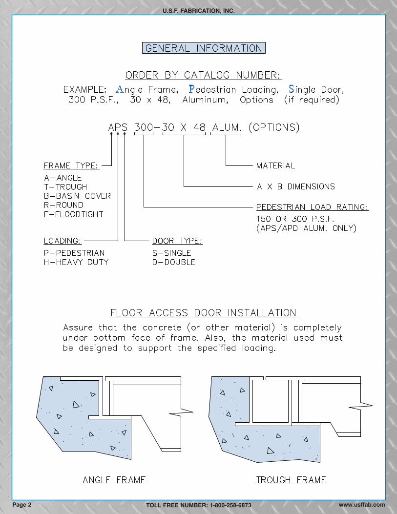
ANGLE FRAME, PEDESTRIAN LOADING, SINGLE DOOR
U.S.F. FABRICATION, INC.
ALUMINUMThe angle frame floor access door is designed for interior and exterior applications where watertightness is not required.
SPECIFICATIONS: The floor access door shall be Model APS as manufactured by U.S.F. Fabrication, Inc. with the size beingspecified on the plans. Door leaf shall be 3/16 or 1/4-inch thick aluminum diamond plate reinforced respectively for a 150 or 300 p.s.f.live load. The frame shall be extruded aluminum with an integral anchor flange and door seat on all four sides. The floor access doorshall be equipped with a flush lifting handle that does not protrude above the cover, and a 316 stainless steel hold open arm withred vinyl grip that automatically keeps the cover in its upright, open position. The door shall have 316 stainless steel hinges with316 stainless steel tamper resistant bolts/locknuts. A staple for a padlock shall be supplied for security. An adhesive backed vinylmaterial that protects the product during shipping and installation shall cover the entire top of the frame and cover. Installation shallbe in accordance with the manufacturerʼs attached instructions. The door shall be manufactured and assembled in the UnitedStates. Manufacturer shall guarantee the door against defects in materials and workmanship for a period of ten years.
OPTIONAL FEATURES
150 P.S.F. LOADING
MODELFRAME OPENING CLEAR OPENING OVERALL SIZE WEIGHT
APS150 3/16 (5) 24 (610) 24 (610) 21 (533) 23 (584) 30 (762) 30 (762) 33 (15)APS150 3/16 (5) 24 (610) 30 (762) 21 (533) 29 (737) 30 (762) 36 (914) 39 (18)APS150 3/16 (5) 24 (610) 36 (914) 21 (533) 35 (889) 30 (762) 42 (1067) 43 (20)APS150 3/16 (5) 30 (762) 30 (762) 27 (686) 29 (737) 36 (914) 36 (914) 45 (20)APS150 3/16 (5) 30 (762) 36 (914) 27 (686) 35 (889) 36 (914) 42 (1067) 50 (23)APS150 3/16 (5) 30 (762) 48 (1219) 27 (686) 47 (1194) 36 (914) 54 (1372) 62 (28)APS150 3/16 (5) 36 (914) 36 (914) 33 (838) 35 (889) 42 (1067) 42 (1067) 57 (26)APS150 3/16 (5) 36 (914) 48 (1219) 33 (838) 47 (1194) 42 (1067) 54 (1372) 71 (32)APS150 3/16 (5) 42 (1067) 42 (1067) 39 (991) 41 (1041) 48 (1219) 48 (1219) 73 (33)
in. (mm) A in. (mm) B in. (mm) C in. (mm) F in. (mm)D in. (mm) E in. (mm) Lbs. (KG)COVER THK
300 P.S.F. LOADING
MODELFRAME OPENING CLEAR OPENING OVERALL SIZE WEIGHT
APS300 1/4 (6) 24 (610) 24 (610) 21 (533) 23 (584) 30 (762) 30 (762) 42 (19)APS300 1/4 (6) 24 (610) 30 (762) 21 (533) 29 (737) 30 (762) 36 (914) 49 (22)APS300 1/4 (6) 24 (610) 36 (914) 21 (533) 35 (889) 30 (762) 42 (1067) 55 (25)APS300 1/4 (6) 30 (762) 30 (762) 27 (686) 29 (737) 36 (914) 36 (914) 57 (26)APS300 1/4 (6) 30 (762) 36 (914) 27 (686) 35 (889) 36 (914) 42 (1067) 64 (29)APS300 1/4 (6) 30 (762) 48 (1219) 27 (686) 47 (1194) 36 (914) 54 (1372) 80 (36)APS300 1/4 (6) 36 (914) 36 (914) 32 (813) 35 (889) 42 (1067) 42 (1067) 73 (33)APS300 1/4 (6) 36 (914) 48 (1219) 32 (813) 47 (1194) 42 (1067) 54 (1372) 92 (42)APS300 1/4 (6) 42 (1067) 42 (1067) 38 (965) 41 (1041) 48 (1219) 48 (1219) 94 (43)
in. (mm) A in. (mm) B in. (mm) C in. (mm) F in. (mm)D in. (mm) E in. (mm) Lbs. (KG)COVER THK
TOLL FREE NUMBER: 1-800-258-6873
AL
UM
IN
UM
� Stainless steel horizontal springs for easy opening,see page 81
� 316 Stainless steel watertight slamlock and otherlocking devices, see page 78
� Bituminous coating on frame surface in contact withconcrete, see page 80
� Frame skirts for easy casting into a concrete top slab,see page 78
� Cushion for noise dampening, see page 79� Fiberglass insulation with metal liner, see page 80
� Nut rails with stainless steel sliding nuts for attachingcable holders, brackets & other hardware, see page 85
� Custom lettering, see page 79� Anodized finish, see page 80� Stainless steel safety chains with aluminum support
posts, see page 80� Fall Through Prevention Systems, see pages 82-83� Slip resistant surface bonded to cover plate, see page 80� Reading Lid, see page 76
Page 4 www.usffab.comWe reserve the right to modify specifications and drawings without prior notice.CUSTOM SIZES READILY AVAILABLE

AL
UM
IN
UM
U.S.F. FABRICATION, INC.
TOLL FREE NUMBER: 1-800-258-6873www.usffab.com Page 5

ANGLE FRAME, PEDESTRIAN LOADING, DOUBLE DOOR
U.S.F. FABRICATION, INC.
ALUMINUMThe angle frame floor access door is designed for interior and exterior applications where watertightness is not required.
SPECIFICATIONS: The floor access door shall be Model APD as manufactured by U.S.F. Fabrication, Inc. with the size beingspecified on the plans. Door leaves shall be 3/16 or 1/4-inch thick aluminum diamond plate reinforced respectively for a 150 or 300p.s.f. live load. The frame shall be extruded aluminum with an integral anchor flange and door seat on all four sides. The floor accessdoor shall be equipped with a flush lifting handle that does not protrude above the cover, and 316 stainless steel hold open arms withred vinyl grips that automatically keep the covers in their upright, open positions. The door shall have 316 stainless steel hinges with316 stainless steel tamper resistant bolts/locknuts. A staple for a padlock shall be supplied for security. An adhesive backed vinylmaterial that protects the product during shipping and installation shall cover the entire top of the frame and covers. Installation shallbe in accordance with the manufacturerʼs attached instructions. The door shall be manufactured and assembled in the UnitedStates. Manufacturer shall guarantee the door against defects in materials and workmanship for a period of ten years.
OPTIONAL FEATURES
150 P.S.F. LOADING
MODELFRAME OPENING CLEAR OPENING OVERALL SIZE WEIGHT
APD150 3/16 (5) 30 (762) 48 (1219) 29 (737) 44 (1118) 36 (914) 54 (1372) 69 (31)APD150 3/16 (5) 30 (762) 54 (1372) 29 (737) 50 (1270) 36 (914) 60 (1524) 75 (34)APD150 3/16 (5) 36 (914) 48 (1219) 35 (889) 44 (1118) 42 (1067) 54 (1372) 78 (35)APD150 3/16 (5) 36 (914) 60 (1524) 35 (889) 55 (1397) 42 (1067) 66 (1676) 92 (42)APD150 3/16 (5) 42 (1067) 48 (1219) 41 (1041) 43 (1092) 48 (1219) 54 (1372) 87 (39)APD150 3/16 (5) 48 (1219) 48 (1219) 47 (1194) 43 (1092) 54 (1372) 54 (1372) 96 (44)APD150 3/16 (5) 48 (1219) 54 (1372) 47 (1194) 48 (1219) 54 (1372) 60 (1524) 107 (49)APD150 3/16 (5) 48 (1219) 72 (1829) 47 (1194) 66 (1676) 54 (1372) 78 (1981) 133 (60)APD150 3/16 (5) 60 (1524) 60 (1524) 59 (1499) 53 (1346) 66 (1676) 66 (1676) 140 (64)
in. (mm) A in. (mm) B in. (mm) C in. (mm) F in. (mm)D in. (mm) E in. (mm) Lbs. (KG)COVER THK
300 P.S.F. LOADING
MODELFRAME OPENING CLEAR OPENING OVERALL SIZE WEIGHT
APD300 1/4 (6) 30 (762) 48 (1219) 29 (737) 44 (1118) 36 (914) 54 (1372) 86 (39)APD300 1/4 (6) 30 (762) 54 (1372) 29 (737) 49 (1245) 36 (914) 60 (1524) 94 (43)APD300 1/4 (6) 36 (914) 48 (1219) 35 (889) 43 (1092) 42 (1067) 54 (1372) 98 (44)APD300 1/4 (6) 36 (914) 60 (1524) 35 (889) 54 (1372) 42 (1067) 66 (1676) 117 (53)APD300 1/4 (6) 42 (1067) 48 (1219) 41 (1041) 42 (1067) 48 (1219) 54 (1372) 110 (50)APD300 1/4 (6) 48 (1219) 48 (1219) 47 (1194) 41 (1041) 54 (1372) 54 (1372) 123 (56)APD300 1/4 (6) 48 (1219) 54 (1372) 47 (1194) 47 (1194) 54 (1372) 60 (1524) 133 (60)APD300 1/4 (6) 48 (1219) 72 (1829) 47 (1194) 65 (1651) 54 (1372) 78 (1981) 170 (77)APD300 1/4 (6) 60 (1524) 60 (1524) 59 (1499) 54 (1372) 66 (1676) 66 (1676) 177 (80)
in. (mm) A in. (mm) B in. (mm) C in. (mm) F in. (mm)D in. (mm) E in. (mm) Lbs. (KG)COVER THK
TOLL FREE NUMBER: 1-800-258-6873
CUSTOM SIZES READILY AVAILABLE
AL
UM
IN
UM
� Stainless steel horizontal springs for easy opening,see page 81
� 316 Stainless steel watertight slamlock and otherlocking devices, see page 78
� Bituminous coating on frame surface in contact withconcrete, see page 80
� Frame skirts for easy casting into a concrete top slab,see page 78
� Cushion for noise dampening, see page 79� Fiberglass insulation with metal liner, see page 80
� Nut rails with stainless steel sliding nuts for attachingcable holders, brackets & other hardware, see page 85
� Custom lettering, see page 79� Anodized finish, see page 80� Stainless steel safety chains, see page 80� Fall Through Prevention Systems, see pages 82-83� Slip resistant surface bonded to cover plate, see page 80� Hinge covers on same long side, see page 84� Reading Lid, see page 76
www.usffab.comPage 6We reserve the right to modify specifications and drawings without prior notice.

AL
UM
IN
UM
U.S.F. FABRICATION, INC.
TOLL FREE NUMBER: 1-800-258-6873 Page 7www.usffab.com
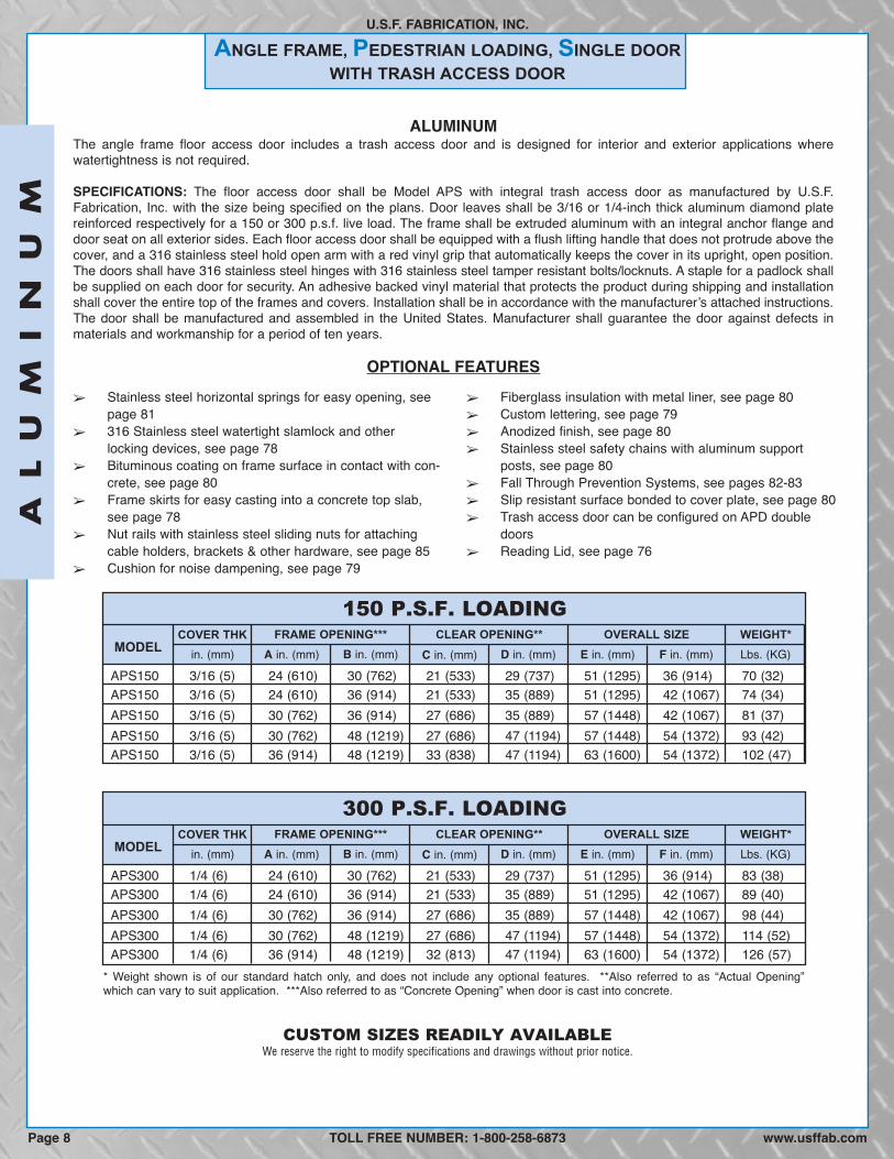
ALUMINUMThe angle frame floor access door includes a trash access door and is designed for interior and exterior applications wherewatertightness is not required.
SPECIFICATIONS: The floor access door shall be Model APS with integral trash access door as manufactured by U.S.F.Fabrication, Inc. with the size being specified on the plans. Door leaves shall be 3/16 or 1/4-inch thick aluminum diamond platereinforced respectively for a 150 or 300 p.s.f. live load. The frame shall be extruded aluminum with an integral anchor flange anddoor seat on all exterior sides. Each floor access door shall be equipped with a flush lifting handle that does not protrude above thecover, and a 316 stainless steel hold open arm with a red vinyl grip that automatically keeps the cover in its upright, open position.The doors shall have 316 stainless steel hinges with 316 stainless steel tamper resistant bolts/locknuts. A staple for a padlock shallbe supplied on each door for security. An adhesive backed vinyl material that protects the product during shipping and installationshall cover the entire top of the frames and covers. Installation shall be in accordance with the manufacturerʼs attached instructions.The door shall be manufactured and assembled in the United States. Manufacturer shall guarantee the door against defects inmaterials and workmanship for a period of ten years.
OPTIONAL FEATURES
150 P.S.F. LOADING
MODELFRAME OPENING*** CLEAR OPENING** OVERALL SIZE WEIGHT*
APS150 3/16 (5) 24 (610) 30 (762) 21 (533) 29 (737) 51 (1295) 36 (914) 70 (32)APS150 3/16 (5) 24 (610) 36 (914) 21 (533) 35 (889) 51 (1295) 42 (1067) 74 (34)APS150 3/16 (5) 30 (762) 36 (914) 27 (686) 35 (889) 57 (1448) 42 (1067) 81 (37)APS150 3/16 (5) 30 (762) 48 (1219) 27 (686) 47 (1194) 57 (1448) 54 (1372) 93 (42)APS150 3/16 (5) 36 (914) 48 (1219) 33 (838) 47 (1194) 63 (1600) 54 (1372) 102 (47)
in. (mm) A in. (mm) B in. (mm) C in. (mm) F in. (mm)D in. (mm) E in. (mm) Lbs. (KG)COVER THK
300 P.S.F. LOADING
MODELFRAME OPENING*** CLEAR OPENING** OVERALL SIZE WEIGHT*
APS300 1/4 (6) 24 (610) 30 (762) 21 (533) 29 (737) 51 (1295) 36 (914) 83 (38)APS300 1/4 (6) 24 (610) 36 (914) 21 (533) 35 (889) 51 (1295) 42 (1067) 89 (40)APS300 1/4 (6) 30 (762) 36 (914) 27 (686) 35 (889) 57 (1448) 42 (1067) 98 (44)APS300 1/4 (6) 30 (762) 48 (1219) 27 (686) 47 (1194) 57 (1448) 54 (1372) 114 (52)APS300 1/4 (6) 36 (914) 48 (1219) 32 (813) 47 (1194) 63 (1600) 54 (1372) 126 (57)
in. (mm) A in. (mm) B in. (mm) C in. (mm) F in. (mm)D in. (mm) E in. (mm) Lbs. (KG)COVER THK
� Stainless steel horizontal springs for easy opening, seepage 81
� 316 Stainless steel watertight slamlock and otherlocking devices, see page 78
� Bituminous coating on frame surface in contact with con-crete, see page 80
� Frame skirts for easy casting into a concrete top slab,see page 78
� Nut rails with stainless steel sliding nuts for attachingcable holders, brackets & other hardware, see page 85
� Cushion for noise dampening, see page 79
� Fiberglass insulation with metal liner, see page 80� Custom lettering, see page 79� Anodized finish, see page 80� Stainless steel safety chains with aluminum support
posts, see page 80� Fall Through Prevention Systems, see pages 82-83� Slip resistant surface bonded to cover plate, see page 80� Trash access door can be configured on APD double
doors� Reading Lid, see page 76
* Weight shown is of our standard hatch only, and does not include any optional features. **Also referred to as “Actual Opening”which can vary to suit application. ***Also referred to as “Concrete Opening” when door is cast into concrete.
TOLL FREE NUMBER: 1-800-258-6873
CUSTOM SIZES READILY AVAILABLE
AL
UM
IN
UM
ANGLE FRAME, PEDESTRIAN LOADING, SINGLE DOORWITH TRASH ACCESS DOOR
U.S.F. FABRICATION, INC.
Page 8 www.usffab.com
We reserve the right to modify specifications and drawings without prior notice.

AL
UM
IN
UM
TOLL FREE NUMBER: 1-800-258-6873
U.S.F. FABRICATION, INC.
www.usffab.com Page 9

ANGLE FRAME, HEAVY-DUTY, SINGLE DOOR
U.S.F. FABRICATION, INC.
ALUMINUMThe heavy-duty angle type floor access door is designed for interior and exterior applications where watertightness is not required.It is designed for off-street locations that may occasionally receive AASHTO H-20-44 wheel loads.
SPECIFICATIONS: The floor access door shall be Model AHS as manufactured by U.S.F. Fabrication, Inc. with the size beingspecified on the plans. Door leaf shall be 1/4-inch thick aluminum diamond plate reinforced for an AASHTO H-20-44 wheel load. Uponrequest, manufacturer shall provide structural calculations showing that the door design meets the loading requirements of AASHTOH20-44. (The floor access door is designed for off-street locations that may occasionally receive AASHTO H-20-44 wheel loads.) Theframe shall be extruded aluminum with an integral anchor flange and door seat on all four sides. The floor access door shall beequipped with a flush lifting handle that does not protrude above the cover, and a 316 stainless steel hold open arm with red vinylgrip that automatically keeps the cover in its upright, open position. The door shall have 316 stainless steel hinges and 316 stainlesssteel tamper resistant bolts/locknuts. The door shall have stainless steel open horizontal springs to assist in opening the cover andreducing the force during closing. The door shall be equipped with a watertight 316 stainless steel slamlock with threaded plug,removable outside key, and fixed inside handle. The slamlock latches onto a 316 stainless steel striker plate that is bolted to the frame.All parts of the frame in contact with concrete shall have a coating of bituminous paint. An adhesive backed vinyl material thatprotects the product during shipping and installation shall cover the entire top of the frame and cover. Installation shall be inaccordance with the manufacturerʼs attached instructions. The entire frame including the seat on which the reinforcing rests shall besupported by concrete or other material designed to support the specified load. The door shall be manufactured and assembled inthe United States. Manufacturer shall guarantee the door against defects in materials and workmanship for a period of ten years.
OPTIONAL FEATURES
H-20 LOADING****
MODELFRAME OPENING*** CLEAR OPENING** OVERALL SIZE WEIGHT*
1/4 (6) 24 (610) 24 (610) 22 (559) 23 (584) 34 (864) 30 (762) 62 (28)1/4 (6) 24 (610) 36 (914) 22 (559) 35 (889) 34 (864) 42 (1067) 87 (39)1/4 (6) 30 (762) 30 (762) 28 (711) 29 (737) 40 (1016) 36 (914) 86 (39)1/4 (6) 30 (762) 36 (914) 28 (711) 35 (889) 40 (1016) 42 (1067) 101 (46)1/4 (6) 30 (762) 48 (1219) 28 (711) 47 (1194) 40 (1016) 54 (1372) 133 (60)1/4 (6) 36 (914) 36 (914) 33 (838) 35 (889) 46 (1168) 42 (1067) 122 (55)
in. (mm) A in. (mm) B in. (mm) C in. (mm) F in. (mm)D in. (mm) E in. (mm) Lbs. (KG)COVER THK
� Enclosed, stainless steel horizontal springs for easyopening, see page 81
� Recessed staple and other locking devices, see page 78� Frame skirts for easy casting into a concrete top slab,
see page 78� Fiberglass insulation with metal liner, see page 80� Custom lettering, see page 79
� Nut rails with stainless steel sliding nuts for attachingcable holders, brackets & other hardware, see page 85
� Anodized finish, see page 80� Stainless steel safety chains with aluminum support
posts, see page 80� Fall Through Prevention Systems, see pages 82-83� Slip resistant surface bonded to cover plate, see page 80
* Weight shown is of our standard hatch only, and does not include any optional features. **Also referred to as “Actual Opening”which can vary to suit application. ***Also referred to as “Concrete Opening” when door is cast into concrete. ****AHS aluminumfloor access doors are intended for off-street locations that may occasionally receive AASHTO H-20-44 wheel loads (16,000 lbs. over10” x 20” area + 30% impact factor). For parking lot applications, see P-AHS and P-AHD (pages 62 to 65). For direct trafficapplications, see steel DT-AHS and DT-AHD (pages 66 to 69). For other direct traffic applications, see cast iron frames &covers (pages 74 to 75).
TOLL FREE NUMBER: 1-800-258-6873
AL
UM
IN
UM
AHSAHSAHSAHSAHSAHS
www.usffab.comPage 10
We reserve the right to modify specifications and drawings without prior notice.CUSTOM SIZES READILY AVAILABLE

AL
UM
IN
UM
U.S.F. FABRICATION, INC.
TOLL FREE NUMBER: 1-800-258-6873www.usffab.com Page 11
ANGLE FRAME, HEAVY-DUTY, DOUBLE DOOR
U.S.F. FABRICATION, INC.
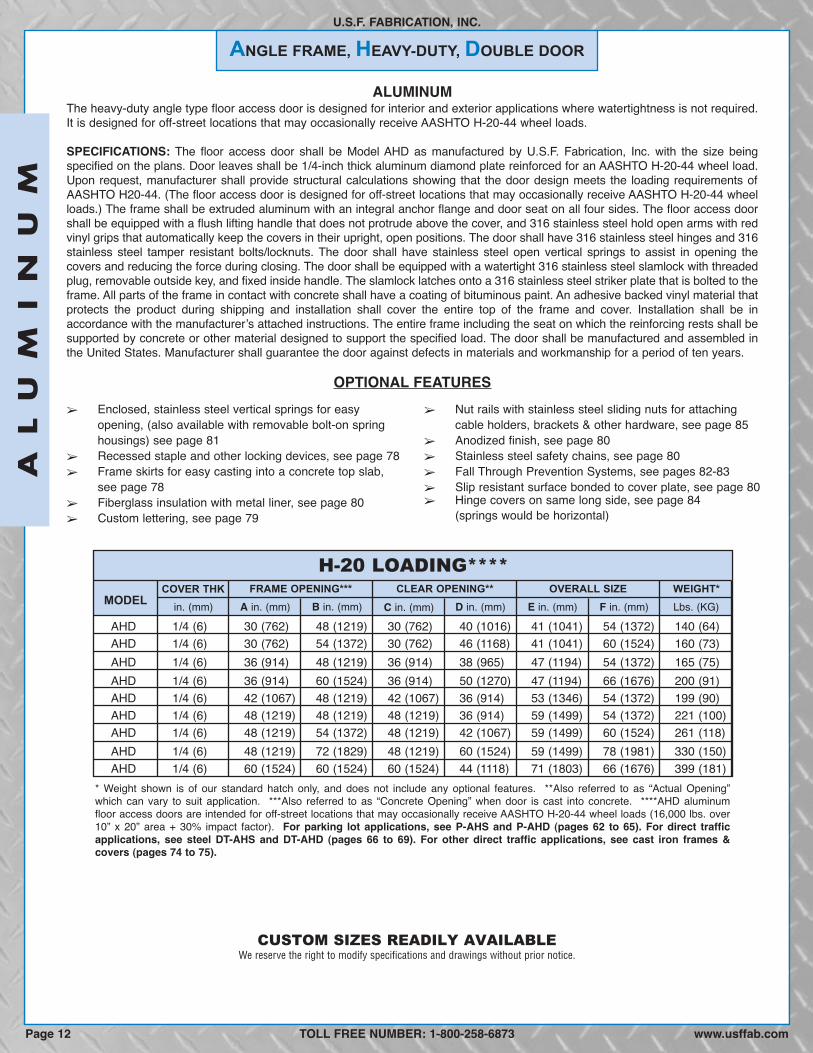
ALUMINUMThe heavy-duty angle type floor access door is designed for interior and exterior applications where watertightness is not required.It is designed for off-street locations that may occasionally receive AASHTO H-20-44 wheel loads.
SPECIFICATIONS: The floor access door shall be Model AHD as manufactured by U.S.F. Fabrication, Inc. with the size beingspecified on the plans. Door leaves shall be 1/4-inch thick aluminum diamond plate reinforced for an AASHTO H-20-44 wheel load.Upon request, manufacturer shall provide structural calculations showing that the door design meets the loading requirements ofAASHTO H20-44. (The floor access door is designed for off-street locations that may occasionally receive AASHTO H-20-44 wheelloads.) The frame shall be extruded aluminum with an integral anchor flange and door seat on all four sides. The floor access doorshall be equipped with a flush lifting handle that does not protrude above the cover, and 316 stainless steel hold open arms with redvinyl grips that automatically keep the covers in their upright, open positions. The door shall have 316 stainless steel hinges and 316stainless steel tamper resistant bolts/locknuts. The door shall have stainless steel open vertical springs to assist in opening thecovers and reducing the force during closing. The door shall be equipped with a watertight 316 stainless steel slamlock with threadedplug, removable outside key, and fixed inside handle. The slamlock latches onto a 316 stainless steel striker plate that is bolted to theframe. All parts of the frame in contact with concrete shall have a coating of bituminous paint. An adhesive backed vinyl material thatprotects the product during shipping and installation shall cover the entire top of the frame and cover. Installation shall be inaccordance with the manufacturerʼs attached instructions. The entire frame including the seat on which the reinforcing rests shall besupported by concrete or other material designed to support the specified load. The door shall be manufactured and assembled inthe United States. Manufacturer shall guarantee the door against defects in materials and workmanship for a period of ten years.
OPTIONAL FEATURES
H-20 LOADING****
MODELFRAME OPENING*** CLEAR OPENING** OVERALL SIZE WEIGHT*
AHD 1/4 (6) 30 (762) 48 (1219) 30 (762) 40 (1016) 41 (1041) 54 (1372) 140 (64)AHD 1/4 (6) 30 (762) 54 (1372) 30 (762) 46 (1168) 41 (1041) 60 (1524) 160 (73)AHD 1/4 (6) 36 (914) 48 (1219) 36 (914) 38 (965) 47 (1194) 54 (1372) 165 (75)AHD 1/4 (6) 36 (914) 60 (1524) 36 (914) 50 (1270) 47 (1194) 66 (1676) 200 (91)AHD 1/4 (6) 42 (1067) 48 (1219) 42 (1067) 36 (914) 53 (1346) 54 (1372) 199 (90)AHD 1/4 (6) 48 (1219) 48 (1219) 48 (1219) 36 (914) 59 (1499) 54 (1372) 221 (100)AHD 1/4 (6) 48 (1219) 54 (1372) 48 (1219) 42 (1067) 59 (1499) 60 (1524) 261 (118)AHD 1/4 (6) 48 (1219) 72 (1829) 48 (1219) 60 (1524) 59 (1499) 78 (1981) 330 (150)AHD 1/4 (6) 60 (1524) 60 (1524) 60 (1524) 44 (1118) 71 (1803) 66 (1676) 399 (181)
in. (mm) A in. (mm) B in. (mm) C in. (mm) F in. (mm)D in. (mm) E in. (mm) Lbs. (KG)COVER THK
� Enclosed, stainless steel vertical springs for easyopening, (also available with removable bolt-on springhousings) see page 81
� Recessed staple and other locking devices, see page 78� Frame skirts for easy casting into a concrete top slab,
see page 78� Fiberglass insulation with metal liner, see page 80� Custom lettering, see page 79
� Nut rails with stainless steel sliding nuts for attachingcable holders, brackets & other hardware, see page 85
� Anodized finish, see page 80� Stainless steel safety chains, see page 80� Fall Through Prevention Systems, see pages 82-83� Slip resistant surface bonded to cover plate, see page 80� Hinge covers on same long side, see page 84
(springs would be horizontal)
* Weight shown is of our standard hatch only, and does not include any optional features. **Also referred to as “Actual Opening”which can vary to suit application. ***Also referred to as “Concrete Opening” when door is cast into concrete. ****AHD aluminumfloor access doors are intended for off-street locations that may occasionally receive AASHTO H-20-44 wheel loads (16,000 lbs. over10” x 20” area + 30% impact factor). For parking lot applications, see P-AHS and P-AHD (pages 62 to 65). For direct trafficapplications, see steel DT-AHS and DT-AHD (pages 66 to 69). For other direct traffic applications, see cast iron frames &covers (pages 74 to 75).
TOLL FREE NUMBER: 1-800-258-6873
CUSTOM SIZES READILY AVAILABLE
AL
UM
IN
UM
Page 12 www.usffab.com
We reserve the right to modify specifications and drawings without prior notice.

AL
UM
IN
UM
U.S.F. FABRICATION, INC.
TOLL FREE NUMBER: 1-800-258-6873 Page 13www.usffab.com
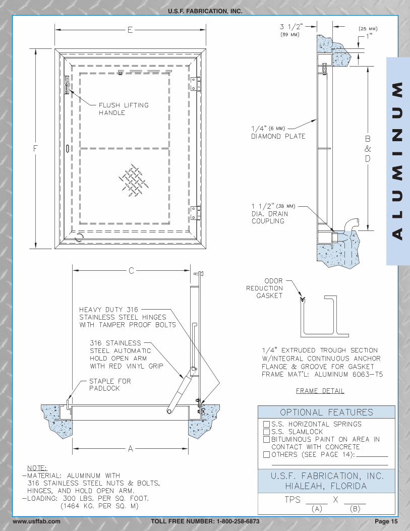
TROUGH FRAME, PEDESTRIAN LOADING, SINGLE DOOR
U.S.F. FABRICATION, INC.
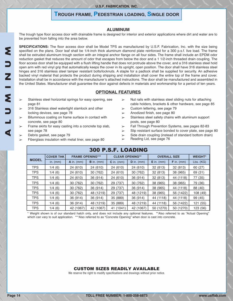
ALUMINUMThe trough type floor access door with drainable frame is designed for interior and exterior applications where dirt and water are tobe prevented from falling into the area below.
SPECIFICATIONS: The floor access door shall be Model TPS as manufactured by U.S.F. Fabrication, Inc. with the size beingspecified on the plans. Door leaf shall be 1/4-inch thick aluminum diamond plate reinforced for a 300 p.s.f. live load. The frameshall be extruded aluminum trough section with an integral anchor flange on all four sides. The frame shall include an EPDM odorreduction gasket that reduces the amount of odor that escapes from below the door and a 1 1/2-inch threaded drain coupling. Thefloor access door shall be equipped with a flush lifting handle that does not protrude above the cover, and a 316 stainless steel holdopen arm with red vinyl grip that automatically keeps the cover in its upright, open position. The door shall have 316 stainless steelhinges and 316 stainless steel tamper resistant bolts/locknuts. A staple for a padlock shall be supplied for security. An adhesivebacked vinyl material that protects the product during shipping and installation shall cover the entire top of the frame and cover.Installation shall be in accordance with the manufacturerʼs attached instructions. The door shall be manufactured and assembled inthe United States. Manufacturer shall guarantee the door against defects in materials and workmanship for a period of ten years.
OPTIONAL FEATURES
300 P.S.F. LOADING
MODELFRAME OPENING*** CLEAR OPENING** OVERALL SIZE WEIGHT*
TPS 1/4 (6) 24 (610) 24 (610) 24 (610) 24 (610) 32 (813) 32 (813) 60 (27)TPS 1/4 (6) 24 (610) 30 (762) 24 (610) 30 (762) 32 (813) 38 (965) 69 (31)TPS 1/4 (6) 24 (610) 36 (914) 24 (610) 36 (914) 32 (813) 44 (1118) 77 (35)TPS 1/4 (6) 30 (762) 30 (762) 29 (737) 30 (762) 38 (965) 38 (965) 79 (36)TPS 1/4 (6) 30 (762) 36 (914) 29 (737) 36 (914) 38 (965) 44 (1118) 88 (40)TPS 1/4 (6) 30 (762) 48 (1219) 29 (737) 48 (1219) 38 (965) 56 (1422) 108 (49)TPS 1/4 (6) 36 (914) 36 (914) 35 (889) 36 (914) 44 (1118) 44 (1118) 99 (45)TPS 1/4 (6) 36 (914) 48 (1219) 35 (889) 48 (1219) 44 (1118) 56 (1422) 121 (55)TPS 1/4 (6) 42 (1067) 42 (1067) 41 (1041) 42 (1067) 50 (1270) 50 (1270) 123 (56)
in. (mm) A in. (mm) B in. (mm) C in. (mm) F in. (mm)D in. (mm) E in. (mm) Lbs. (KG)COVER THK
� Stainless steel horizontal springs for easy opening, seepage 81
� 316 Stainless steel watertight slamlock and otherlocking devices, see page 78
� Bituminous coating on frame surface in contact withconcrete, see page 80
� Frame skirts for easy casting into a concrete top slab,see page 78
� Debris gasket, see page 79� Fiberglass insulation with metal liner, see page 80
� Nut rails with stainless steel sliding nuts for attachingcable holders, brackets & other hardware, see page 85
� Custom lettering, see page 79� Anodized finish, see page 80� Stainless steel safety chains with aluminum support
posts, see page 80� Fall Through Prevention Systems, see pages 82-83� Slip resistant surface bonded to cover plate, see page 80� Side drain coupling (instead of standard bottom drain)� Reading Lid, see page 76
CUSTOM SIZES READILY AVAILABLE
* Weight shown is of our standard hatch only, and does not include any optional features. **Also referred to as “Actual Opening”which can vary to suit application. ***Also referred to as “Concrete Opening” when door is cast into concrete.
TOLL FREE NUMBER: 1-800-258-6873
AL
UM
IN
UM
Page 14 www.usffab.com
We reserve the right to modify specifications and drawings without prior notice.
AL
UM
IN
UM
U.S.F. FABRICATION, INC.
TOLL FREE NUMBER: 1-800-258-6873www.usffab.com Page 15

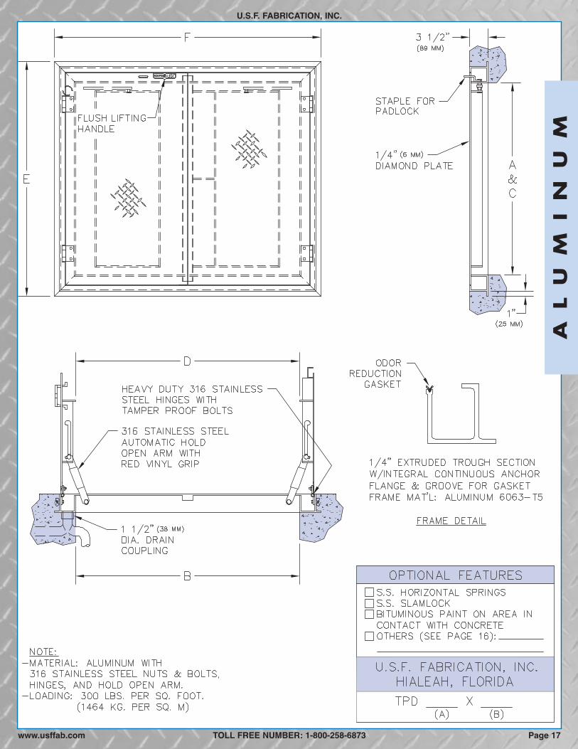
TROUGH FRAME, PEDESTRIAN LOADING, DOUBLE DOOR
U.S.F. FABRICATION, INC.
ALUMINUMThe trough type floor access door with drainable frame is designed for interior and exterior applications where dirt and water are tobe prevented from falling into the area below.
SPECIFICATIONS: The floor access door shall be Model TPD as manufactured by U.S.F. Fabrication, Inc. with the size beingspecified on the plans. Door leaves shall be 1/4-inch thick aluminum diamond plate reinforced for a 300 p.s.f. live load. The frameshall be extruded aluminum trough section with an integral anchor flange on all four sides. The frame shall include an EPDM odorreduction gasket that reduces the amount of odor that escapes from below the door and a 1 1/2-inch threaded drain coupling. Thefloor access door shall be equipped with a flush lifting handle that does not protrude above the cover and 316 stainless steel holdopen arms with red vinyl grips that automatically keep the covers in their upright, open positions. The door shall have 316 stainlesssteel hinges and 316 stainless steel tamper resistant bolts/locknuts. A staple for a padlock shall be supplied for security. Anadhesive backed vinyl material that protects the product during shipping and installation shall cover the entire top of the frame andcovers. Installation shall be in accordance with the manufacturerʼs attached instructions. The door shall be manufactured andassembled in the United States. Manufacturer shall guarantee the door against defects in materials and workmanship for a periodof ten years.
OPTIONAL FEATURES
300 P.S.F. LOADING
MODELFRAME OPENING*** CLEAR OPENING** OVERALL SIZE WEIGHT*
TPD 1/4 (6) 30 (762) 48 (1219) 30 (762) 47 (1194) 38 (965) 56 (1422) 115 (52)TPD 1/4 (6) 30 (762) 54 (1372) 30 (762) 53 (1346) 38 (965) 62 (1575) 124 (56)TPD 1/4 (6) 36 (914) 48 (1219) 36 (914) 46 (1168) 44 (1118) 56 (1422) 129 (59)TPD 1/4 (6) 36 (914) 60 (1524) 36 (914) 58 (1473) 44 (1118) 68 (1727) 152 (69)TPD 1/4 (6) 42 (1067) 48 (1219) 42 (1067) 45 (1143) 50 (1270) 56 (1422) 144 (65)TPD 1/4 (6) 48 (1219) 48 (1219) 48 (1219) 45 (1143) 56 (1422) 56 (1422) 158 (72)TPD 1/4 (6) 48 (1219) 54 (1372) 48 (1219) 50 (1270) 56 (1422) 62 (1575) 173 (78)TPD 1/4 (6) 48 (1219) 72 (1829) 48 (1219) 70 (1778) 56 (1422) 80 (2032) 215 (98)TPD 1/4 (6) 60 (1524) 60 (1524) 60 (1524) 58 (1473) 68 (1727) 68 (1727) 223 (101)
in. (mm) A in. (mm) B in. (mm) C in. (mm) F in. (mm)D in. (mm) E in. (mm) Lbs. (KG)COVER THK
� Stainless steel horizontal springs for easy opening, seepage 81
� 316 Stainless steel watertight slamlock and otherlocking devices, see page 78
� Bituminous coating on frame surface in contact withconcrete, see page 80
� Frame skirts for easy casting into a concrete top slab,see page 78
� Debris gasket, see page 79� Fiberglass insulation with metal liner, see page 80
� Nut rails with stainless steel sliding nuts for attachingcable holders, brackets & other hardware, see page 85
� Custom lettering, see page 79� Anodized finish, see page 80� Stainless steel safety chains, see page 80� Fall Through Prevention Systems, see pages 82-83� Slip resistant surface bonded to cover plate, see page 80� Side drain coupling (instead of standard bottom drain)� Hinge covers on same long side, see page 84� Reading Lid, see page 76
CUSTOM SIZES READILY AVAILABLE
* Weight shown is of our standard hatch only, and does not include any optional features. **Also referred to as “Actual Opening”which can vary to suit application. ***Also referred to as “Concrete Opening” when door is cast into concrete.
TOLL FREE NUMBER: 1-800-258-6873
AL
UM
IN
UM
www.usffab.comPage 16
We reserve the right to modify specifications and drawings without prior notice.
AL
UM
IN
UM
U.S.F. FABRICATION, INC.
TOLL FREE NUMBER: 1-800-258-6873 Page 17www.usffab.com
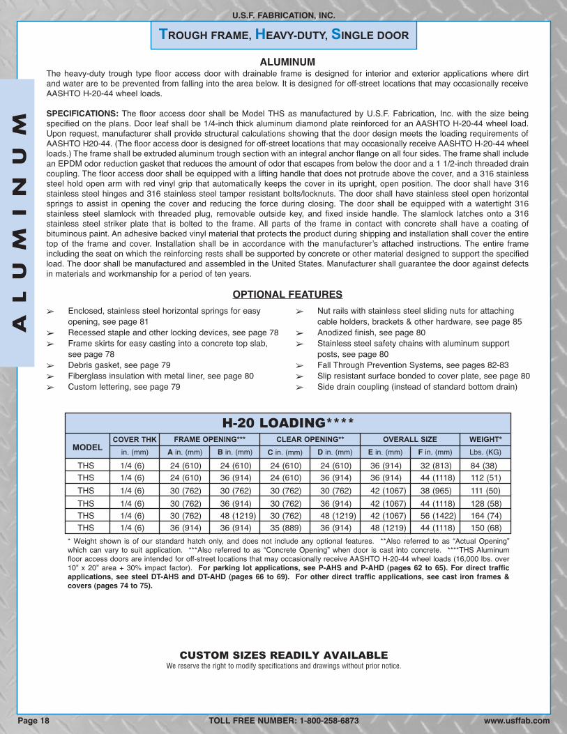
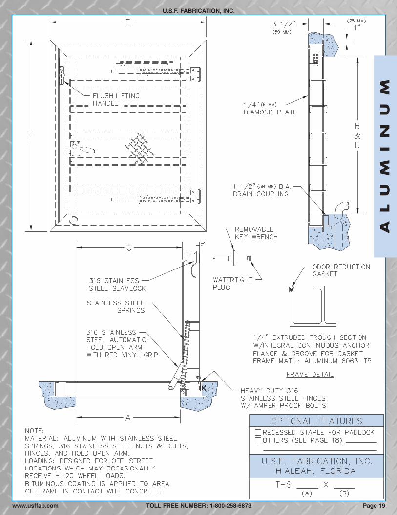
TROUGH FRAME, HEAVY-DUTY, SINGLE DOOR
U.S.F. FABRICATION, INC.
ALUMINUMThe heavy-duty trough type floor access door with drainable frame is designed for interior and exterior applications where dirtand water are to be prevented from falling into the area below. It is designed for off-street locations that may occasionally receiveAASHTO H-20-44 wheel loads.
SPECIFICATIONS: The floor access door shall be Model THS as manufactured by U.S.F. Fabrication, Inc. with the size beingspecified on the plans. Door leaf shall be 1/4-inch thick aluminum diamond plate reinforced for an AASHTO H-20-44 wheel load.Upon request, manufacturer shall provide structural calculations showing that the door design meets the loading requirements ofAASHTO H20-44. (The floor access door is designed for off-street locations that may occasionally receive AASHTO H-20-44 wheelloads.) The frame shall be extruded aluminum trough section with an integral anchor flange on all four sides. The frame shall includean EPDM odor reduction gasket that reduces the amount of odor that escapes from below the door and a 1 1/2-inch threaded draincoupling. The floor access door shall be equipped with a lifting handle that does not protrude above the cover, and a 316 stainlesssteel hold open arm with red vinyl grip that automatically keeps the cover in its upright, open position. The door shall have 316stainless steel hinges and 316 stainless steel tamper resistant bolts/locknuts. The door shall have stainless steel open horizontalsprings to assist in opening the cover and reducing the force during closing. The door shall be equipped with a watertight 316stainless steel slamlock with threaded plug, removable outside key, and fixed inside handle. The slamlock latches onto a 316stainless steel striker plate that is bolted to the frame. All parts of the frame in contact with concrete shall have a coating ofbituminous paint. An adhesive backed vinyl material that protects the product during shipping and installation shall cover the entiretop of the frame and cover. Installation shall be in accordance with the manufacturerʼs attached instructions. The entire frameincluding the seat on which the reinforcing rests shall be supported by concrete or other material designed to support the specifiedload. The door shall be manufactured and assembled in the United States. Manufacturer shall guarantee the door against defectsin materials and workmanship for a period of ten years.
OPTIONAL FEATURES
H-20 LOADING****
MODELFRAME OPENING*** CLEAR OPENING** OVERALL SIZE WEIGHT*
THS 1/4 (6) 24 (610) 24 (610) 24 (610) 24 (610) 36 (914) 32 (813) 84 (38)THS 1/4 (6) 24 (610) 36 (914) 24 (610) 36 (914) 36 (914) 44 (1118) 112 (51)THS 1/4 (6) 30 (762) 30 (762) 30 (762) 30 (762) 42 (1067) 38 (965) 111 (50)THS 1/4 (6) 30 (762) 36 (914) 30 (762) 36 (914) 42 (1067) 44 (1118) 128 (58)THS 1/4 (6) 30 (762) 48 (1219) 30 (762) 48 (1219) 42 (1067) 56 (1422) 164 (74)THS 1/4 (6) 36 (914) 36 (914) 35 (889) 36 (914) 48 (1219) 44 (1118) 150 (68)
in. (mm) A in. (mm) B in. (mm) C in. (mm) F in. (mm)D in. (mm) E in. (mm) Lbs. (KG)COVER THK
� Enclosed, stainless steel horizontal springs for easyopening, see page 81
� Recessed staple and other locking devices, see page 78� Frame skirts for easy casting into a concrete top slab,
see page 78� Debris gasket, see page 79� Fiberglass insulation with metal liner, see page 80� Custom lettering, see page 79
� Nut rails with stainless steel sliding nuts for attachingcable holders, brackets & other hardware, see page 85
� Anodized finish, see page 80� Stainless steel safety chains with aluminum support
posts, see page 80� Fall Through Prevention Systems, see pages 82-83� Slip resistant surface bonded to cover plate, see page 80� Side drain coupling (instead of standard bottom drain)
* Weight shown is of our standard hatch only, and does not include any optional features. **Also referred to as “Actual Opening”which can vary to suit application. ***Also referred to as “Concrete Opening” when door is cast into concrete. ****THS Aluminumfloor access doors are intended for off-street locations that may occasionally receive AASHTO H-20-44 wheel loads (16,000 lbs. over10” x 20” area + 30% impact factor). For parking lot applications, see P-AHS and P-AHD (pages 62 to 65). For direct trafficapplications, see steel DT-AHS and DT-AHD (pages 66 to 69). For other direct traffic applications, see cast iron frames &covers (pages 74 to 75).
TOLL FREE NUMBER: 1-800-258-6873
CUSTOM SIZES READILY AVAILABLE
AL
UM
IN
UM
Page 18 www.usffab.com
We reserve the right to modify specifications and drawings without prior notice.
AL
UM
IN
UM
U.S.F. FABRICATION, INC.
TOLL FREE NUMBER: 1-800-258-6873 Page 19www.usffab.com
TROUGH FRAME, HEAVY-DUTY, DOUBLE DOOR
U.S.F. FABRICATION, INC.
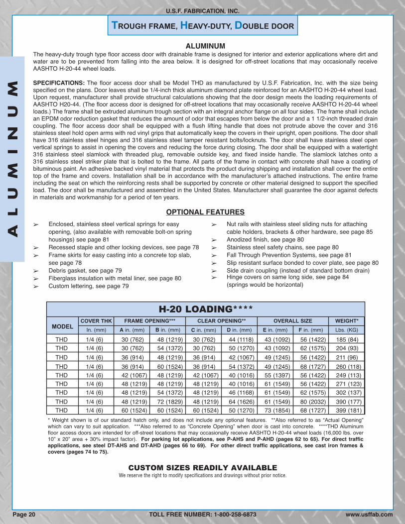
ALUMINUMThe heavy-duty trough type floor access door with drainable frame is designed for interior and exterior applications where dirt andwater are to be prevented from falling into the area below. It is designed for off-street locations that may occasionally receiveAASHTO H-20-44 wheel loads.
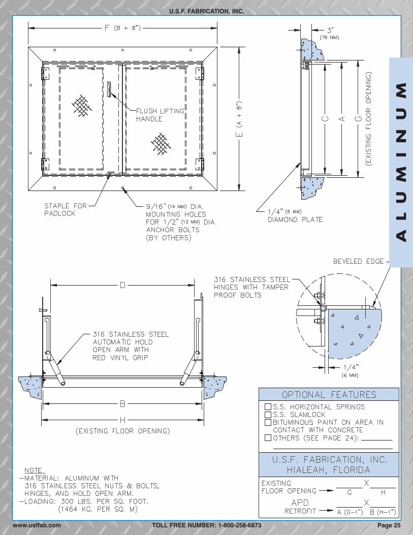
SPECIFICATIONS: The floor access door shall be Model THD as manufactured by U.S.F. Fabrication, Inc. with the size beingspecified on the plans. Door leaves shall be 1/4-inch thick aluminum diamond plate reinforced for an AASHTO H-20-44 wheel load.Upon request, manufacturer shall provide structural calculations showing that the door design meets the loading requirements ofAASHTO H20-44. (The floor access door is designed for off-street locations that may occasionally receive AASHTO H-20-44 wheelloads.) The frame shall be extruded aluminum trough section with an integral anchor flange on all four sides. The frame shall includean EPDM odor reduction gasket that reduces the amount of odor that escapes from below the door and a 1 1/2-inch threaded draincoupling. The floor access door shall be equipped with a flush lifting handle that does not protrude above the cover and 316stainless steel hold open arms with red vinyl grips that automatically keep the covers in their upright, open positions. The door shallhave 316 stainless steel hinges and 316 stainless steel tamper resistant bolts/locknuts. The door shall have stainless steel openvertical springs to assist in opening the covers and reducing the force during closing. The door shall be equipped with a watertight316 stainless steel slamlock with threaded plug, removable outside key, and fixed inside handle. The slamlock latches onto a316 stainless steel striker plate that is bolted to the frame. All parts of the frame in contact with concrete shall have a coating ofbituminous paint. An adhesive backed vinyl material that protects the product during shipping and installation shall cover the entiretop of the frame and covers. Installation shall be in accordance with the manufacturerʼs attached instructions. The entire frameincluding the seat on which the reinforcing rests shall be supported by concrete or other material designed to support the specifiedload. The door shall be manufactured and assembled in the United States. Manufacturer shall guarantee the door against defectsin materials and workmanship for a period of ten years.
OPTIONAL FEATURES
H-20 LOADING****
MODELFRAME OPENING*** CLEAR OPENING** OVERALL SIZE WEIGHT*
THD 1/4 (6) 30 (762) 48 (1219) 30 (762) 44 (1118) 43 (1092) 56 (1422) 185 (84)THD 1/4 (6) 30 (762) 54 (1372) 30 (762) 50 (1270) 43 (1092) 62 (1575) 204 (93)THD 1/4 (6) 36 (914) 48 (1219) 36 (914) 42 (1067) 49 (1245) 56 (1422) 211 (96)THD 1/4 (6) 36 (914) 60 (1524) 36 (914) 54 (1372) 49 (1245) 68 (1727) 260 (118)THD 1/4 (6) 42 (1067) 48 (1219) 42 (1067) 40 (1016) 55 (1397) 56 (1422) 249 (113)THD 1/4 (6) 48 (1219) 48 (1219) 48 (1219) 40 (1016) 61 (1549) 56 (1422) 271 (123)THD 1/4 (6) 48 (1219) 54 (1372) 48 (1219) 46 (1168) 61 (1549) 62 (1575) 302 (137)THD 1/4 (6) 48 (1219) 72 (1829) 48 (1219) 64 (1626) 61 (1549) 80 (2032) 390 (177)THD 1/4 (6) 60 (1524) 60 (1524) 60 (1524) 50 (1270) 73 (1854) 68 (1727) 399 (181)
In. (mm) A in. (mm) B in. (mm) C in. (mm) F in. (mm)D in. (mm) E in. (mm) Lbs. (KG)COVER THK
� Enclosed, stainless steel vertical springs for easyopening, (also available with removable bolt-on springhousings) see page 81
� Recessed staple and other locking devices, see page 78� Frame skirts for easy casting into a concrete top slab,
see page 78� Debris gasket, see page 79� Fiberglass insulation with metal liner, see page 80� Custom lettering, see page 79
� Nut rails with stainless steel sliding nuts for attachingcable holders, brackets & other hardware, see page 85
� Anodized finish, see page 80� Stainless steel safety chains, see page 80� Fall Through Prevention Systems, see page 81� Slip resistant surface bonded to cover plate, see page 80� Side drain coupling (instead of standard bottom drain)� Hinge covers on same long side, see page 84
(springs would be horizontal)
* Weight shown is of our standard hatch only, and does not include any optional features. **Also referred to as “Actual Opening”which can vary to suit application. ***Also referred to as “Concrete Opening” when door is cast into concrete. ****THD Aluminumfloor access doors are intended for off-street locations that may occasionally receive AASHTO H-20-44 wheel loads (16,000 lbs. over10” x 20” area + 30% impact factor). For parking lot applications, see P-AHS and P-AHD (pages 62 to 65). For direct trafficapplications, see steel DT-AHS and DT-AHD (pages 66 to 69). For other direct traffic applications, see cast iron frames &covers (pages 74 to 75).
TOLL FREE NUMBER: 1-800-258-6873
CUSTOM SIZES READILY AVAILABLE
AL
UM
IN
UM
www.usffab.comPage 20
We reserve the right to modify specifications and drawings without prior notice.

AL
UM
IN
UM
U.S.F. FABRICATION, INC.
TOLL FREE NUMBER: 1-800-258-6873 Page 21www.usffab.com

ANGLE FRAME, PEDESTRIAN LOADING, SINGLE DOORRETROFIT
U.S.F. FABRICATION, INC.
ALUMINUMThe retrofit angle frame floor access door is designed for interior and exterior applications where watertightness is not required andthe frame is to be placed into an existing opening.
SPECIFICATIONS: The retrofit floor access door shall be Model APS RETROFIT as manufactured by U.S.F. Fabrication, Inc. withthe size being specified on the plans. Door leaf shall be 1/4-inch thick aluminum diamond plate reinforced for a 300 p.s.f. live load.The extruded aluminum angle frame shall have a horizontal flange with 9/16-inch diameter holes for bolting to the existing floor andan integral door seat on all four sides. The horizontal flange will have a beveled edge that slopes to the floor surface. The flooraccess door shall be equipped with a flush lifting handle that does not protrude above the cover, and a 316 stainless steel hold openarm with red vinyl grip that automatically keeps the cover in its upright, open position. The door shall have 316 stainless steelhinges and 316 stainless steel tamper resistant bolts/locknuts. A staple for a padlock shall be supplied for security. The door shallbe manufactured and assembled in the United States. Manufacturer shall guarantee the door against defects in materials andworkmanship for a period of ten years.
OPTIONAL FEATURES
300 P.S.F. LOADING
MODELFRAME OPENING CLEAR OPENING** EXISTING OPENING WEIGHT*
APS300 1/4 (6) 23 (584) 23 (584) 20 (508) 22 (559) 24 (610) 24 (610) 41 (19)APS300 1/4 (6) 23 (584) 29 (737) 20 (508) 28 (711) 24 (610) 30 (762) 48 (22)APS300 1/4 (6) 23 (584) 35 (889) 20 (508) 34 (864) 24 (610) 36 (914) 54 (24)APS300 1/4 (6) 29 (737) 29 (737) 26 (660) 28 (711) 30 (762) 30 (762) 56 (25)APS300 1/4 (6) 29 (737) 35 (889) 26 (660) 34 (864) 30 (762) 36 (914) 63 (29)APS300 1/4 (6) 29 (737) 47 (1194) 26 (660) 46 (1168) 30 (762) 48 (1219) 79 (36)APS300 1/4 (6) 35 (889) 35 (889) 31 (787) 34 (864) 36 (914) 36 (914) 72 (33)APS300 1/4 (6) 35 (889) 47 (1194) 31 (787) 46 (1168) 36 (914) 48 (1219) 91 (41)APS300 1/4 (6) 41 (1041) 41 (1041) 37 (940) 40 (1016) 42 (1067) 42 (1067) 93 (42)
in. (mm) A in. (mm) B in. (mm) C in. (mm) H in. (mm)D in. (mm) G in. (mm) Lbs. (KG)COVER THK
� Stainless steel horizontal springs for easy opening, seepage 81
� 316 Stainless steel watertight slamlock and otherlocking devices, see page 78
� Bituminous coating on frame surface in contact withconcrete, see page 80
� Cushion for noise dampening, see page 79� Nut rails with stainless steel sliding nuts for attaching
cable holders, brackets & other hardware, see page 85� Fiberglass insulation with metal liner, see page 80
� Custom lettering, see page 79� Anodized finish, see page 80� Stainless steel safety chains with aluminum support
posts, see page 80� Fall Through Prevention Systems, see pages 82-83� Slip resistant surface bonded to cover plate, see page 80� All steel or stainless steel material (no beveled edge)� Mounting holes on verticle/inside frame wall for security� Reading Lid, see page 76
TOLL FREE NUMBER: 1-800-258-6873
CUSTOM SIZES READILY AVAILABLE
AL
UM
IN
UM
www.usffab.comPage 22
We reserve the right to modify specifications and drawings without prior notice.
* Weight shown is of our standard hatch only, and does not include any optional features. **Also referred to as “Actual Opening”which can vary to suit application.

AL
UM
IN
UM
U.S.F. FABRICATION, INC.
TOLL FREE NUMBER: 1-800-258-6873 Page 23www.usffab.com

ANGLE FRAME, PEDESTRIAN LOADING, DOUBLE DOORRETROFIT
U.S.F. FABRICATION, INC.
ALUMINUMThe retrofit angle frame floor access door is designed for interior and exterior applications where watertightness is not required andthe frame is to be placed into an existing opening.
SPECIFICATIONS: The retrofit floor access door shall be Model APD RETROFIT as manufactured by U.S.F. Fabrication, Inc. withthe size being specified on the plans. Door leaves shall be 1/4-inch thick aluminum diamond plate reinforced for a 300 p.s.f. liveload. The extruded aluminum angle frame shall have a horizontal flange with 9/16-inch diameter holes for bolting to the existing floorand an integral door seat on all four sides. The horizontal flange will have a beveled edge that slopes to the floor surface. The flooraccess door shall be equipped with a flush lifting handle that does not protrude above the cover, and 316 stainless steel hold openarms with red vinyl grips that automatically keep the covers in their upright, open position. The door shall have 316 stainless steelhinges and 316 stainless steel tamper resistant bolts/locknuts. A staple for a padlock shall be supplied for security. The door shallbe manufactured and assembled in the United States. Manufacturer shall guarantee the door against defects in materials andworkmanship for a period of ten years.
OPTIONAL FEATURES
300 P.S.F. LOADING
MODELFRAME OPENING CLEAR OPENING** EXISTING OPENING WEIGHT*
APD300 1/4 (6) 29 (737) 47 (1194) 28 (711) 43 (1092) 30 (762) 48 (1219) 85 (39)APD300 1/4 (6) 29 (737) 53 (1346) 28 (711) 49 (1245) 30 (762) 54 (1372) 93 (42)APD300 1/4 (6) 35 (889) 47 (1194) 34 (864) 42 (1067) 36 (914) 48 (1219) 97 (44)APD300 1/4 (6) 35 (889) 59 (1499) 34 (864) 53 (1346) 36 (914) 60 (1524) 115 (52)APD300 1/4 (6) 41 (1041) 47 (1194) 40 (1016) 41 (1041) 42 (1067) 48 (1219) 109 (49)APD300 1/4 (6) 47 (1194) 47 (1194) 46 (1168) 40 (1016) 48 (1219) 48 (1219) 121 (55)APD300 1/4 (6) 47 (1194) 53 (1346) 46 (1168) 46 (1168) 48 (1219) 54 (1372) 132 (60)APD300 1/4 (6) 47 (1194) 71 (1803) 46 (1168) 64 (1626) 48 (1219) 72 (1829) 169 (77)APD300 1/4 (6) 59 (1499) 59 (1499) 58 (1473) 53 (1346) 60 (1524) 60 (1524) 172 (78)
in. (mm) A in. (mm) B in. (mm) C in. (mm) H in. (mm)D in. (mm) G in. (mm) Lbs. (KG)COVER THK
� Stainless steel horizontal springs for easy opening, seepage 81
� 316 Stainless steel watertight slamlock and otherlocking devices, see page 78
� Bituminous coating on frame surface in contact withconcrete, see page 80
� Cushion for noise dampening, see page 79� Nut rails with stainless steel sliding nuts for attaching
cable holders, brackets & other hardware, see page 85� Fiberglass insulation with metal liner, see page 80
� Custom lettering, see page 79� Anodized finish, see page 80� Stainless steel safety chains, see page 80� Fall Through Prevention Systems, see pages 82-83� Slip resistant surface bonded to cover plate, see page 80� All steel or stainless steel material (no beveled edges)� Hinge covers on same long side, see page 84� Mounting holes on verticle/inside frame wall for security� Reading Lid, see page 76
CUSTOM SIZES READILY AVAILABLE
TOLL FREE NUMBER: 1-800-258-6873
AL
UM
IN
UM
www.usffab.comPage 24
We reserve the right to modify specifications and drawings without prior notice.
* Weight shown is of our standard hatch only, and does not include any optional features. **Also referred to as “Actual Opening”which can vary to suit application.
AL
UM
IN
UM
U.S.F. FABRICATION, INC.
TOLL FREE NUMBER: 1-800-258-6873 Page 25www.usffab.com
BASIN COVER, PEDESTRIAN LOADING, SINGLE DOOR
U.S.F. FABRICATION, INC.
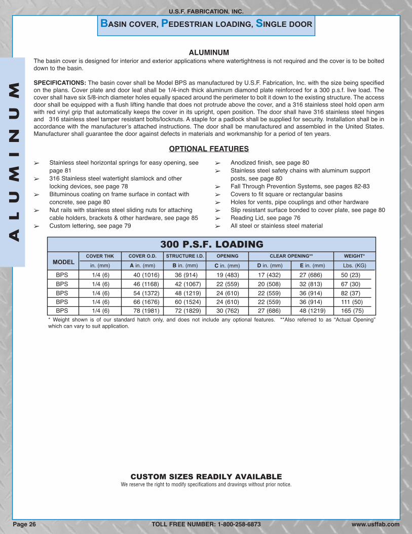
ALUMINUMThe basin cover is designed for interior and exterior applications where watertightness is not required and the cover is to be bolteddown to the basin.
SPECIFICATIONS: The basin cover shall be Model BPS as manufactured by U.S.F. Fabrication, Inc. with the size being specifiedon the plans. Cover plate and door leaf shall be 1/4-inch thick aluminum diamond plate reinforced for a 300 p.s.f. live load. Thecover shall have six 5/8-inch diameter holes equally spaced around the perimeter to bolt it down to the existing structure. The accessdoor shall be equipped with a flush lifting handle that does not protrude above the cover, and a 316 stainless steel hold open armwith red vinyl grip that automatically keeps the cover in its upright, open position. The door shall have 316 stainless steel hingesand 316 stainless steel tamper resistant bolts/locknuts. A staple for a padlock shall be supplied for security. Installation shall be inaccordance with the manufacturerʼs attached instructions. The door shall be manufactured and assembled in the United States.Manufacturer shall guarantee the door against defects in materials and workmanship for a period of ten years.
OPTIONAL FEATURES
300 P.S.F. LOADING
MODELCOVER O.D. STRUCTURE I.D. OPENING CLEAR OPENING** WEIGHT*
BPS 1/4 (6) 78 (1981) 72 (1829) 30 (762) 27 (686) 48 (1219) 165 (75)BPS 1/4 (6) 66 (1676) 60 (1524) 24 (610) 22 (559) 36 (914) 111 (50)BPS 1/4 (6) 54 (1372) 48 (1219) 24 (610) 22 (559) 36 (914) 82 (37)BPS 1/4 (6) 46 (1168) 42 (1067) 22 (559) 20 (508) 32 (813) 67 (30)BPS 1/4 (6) 40 (1016) 36 (914) 19 (483) 17 (432) 27 (686) 50 (23)
in. (mm) A in. (mm) B in. (mm) C in. (mm) Lbs. (KG)D in. (mm) E in. (mm)COVER THK
� Stainless steel horizontal springs for easy opening, seepage 81
� 316 Stainless steel watertight slamlock and otherlocking devices, see page 78
� Bituminous coating on frame surface in contact withconcrete, see page 80
� Nut rails with stainless steel sliding nuts for attachingcable holders, brackets & other hardware, see page 85
� Custom lettering, see page 79
� Anodized finish, see page 80� Stainless steel safety chains with aluminum support
posts, see page 80� Fall Through Prevention Systems, see pages 82-83� Covers to fit square or rectangular basins� Holes for vents, pipe couplings and other hardware� Slip resistant surface bonded to cover plate, see page 80� Reading Lid, see page 76� All steel or stainless steel material
* Weight shown is of our standard hatch only, and does not include any optional features. **Also referred to as “Actual Opening”which can vary to suit application.
CUSTOM SIZES READILY AVAILABLE
TOLL FREE NUMBER: 1-800-258-6873
AL
UM
IN
UM
www.usffab.comPage 26
We reserve the right to modify specifications and drawings without prior notice.

AL
UM
IN
UM
U.S.F. FABRICATION, INC.
TOLL FREE NUMBER: 1-800-258-6873 Page 27www.usffab.com

BASIN, PEDESTRIAN COVER
U.S.F. FABRICATION, INC.
ALUMINUMThe basin cover is designed for interior and exterior applications where watertightness is not required. This economical design hasthe cover bolted directly to the basin without a frame, hold open arm or springs, which allows the cover to open a full 180 degrees.
SPECIFICATIONS: The basin cover shall be Model BPC as manufactured by U.S.F. Fabrication, Inc. with the size being specifiedon the plans. Cover plate shall be 1/4-inch thick aluminum diamond plate reinforced for a 300 p.s.f. live load. The fixed section ofthe cover shall have three 5/8-inch diameter holes equally spaced on the perimeter to bolt it down to the existing structure. Theaccess door shall be equipped with a flush lifting handle that does not protrude above the cover. The door shall have a 304 stain-less steel continous hinge and 316 stainless steel tamper proof bolts/locknuts, which allow the cover to open a full 180degrees. A staple for a padlock shall be supplied for security. Installation shall be in accordance with the manufacturerʼs attachedinstructions. The door shall be manufactured and assembled in the United States. Manufacturer shall guarantee the door againstdefects in materials and workmanship for a period of ten years.
OPTIONAL FEATURES
300 P.S.F. LOADING
MODELCOVER O.D. STRUCTURE I.D. CLEAR OPENING** WEIGHT*
BPC 1/4 (6) 40 (1016) 36 (914) 24 (610) 40 (18)BPC 1/4 (6) 46 (1168) 42 (1067) 28 (711) 53 (24)BPC 1/4 (6) 54 (1372) 48 (1219) 32 (813) 82 (37)BPC 1/4 (6) 66 (1676) 60 (1524) 40 (1016) 121 (55)
in. (mm) A in. (mm) B in. (mm) C in. (mm) Lbs. (KG)COVER THK
� Nut rails with stainless steel sliding nuts for attachingcable holders, brackets & other hardware, see page 85
� Custom lettering, see page 79� Anodized finish, see page 80
� Covers to fit square or retangular basins� Holes for vents, pipe couplings and other hardware� Slip resistant surface bonded to cover plate, see page 80� All steel or stainless steel material
* Weight shown is of our standard hatch only, and does not include any optional features. **Also referred to as “Actual Opening”which can vary to suit application.
CUSTOM SIZES READILY AVAILABLE
TOLL FREE NUMBER: 1-800-258-6873
AL
UM
IN
UM
www.usffab.comPage 28
We reserve the right to modify specifications and drawings without prior notice.

AL
UM
IN
UM
U.S.F. FABRICATION, INC.
TOLL FREE NUMBER: 1-800-258-6873 Page 29www.usffab.com

ROUND FRAME, PEDESTRIAN LOADING, SINGLE DOOR
U.S.F. FABRICATION, INC.
ALUMINUMThe round floor access door is designed for interior and exterior applications where watertightness is not required and the frame isto be cast into concrete.
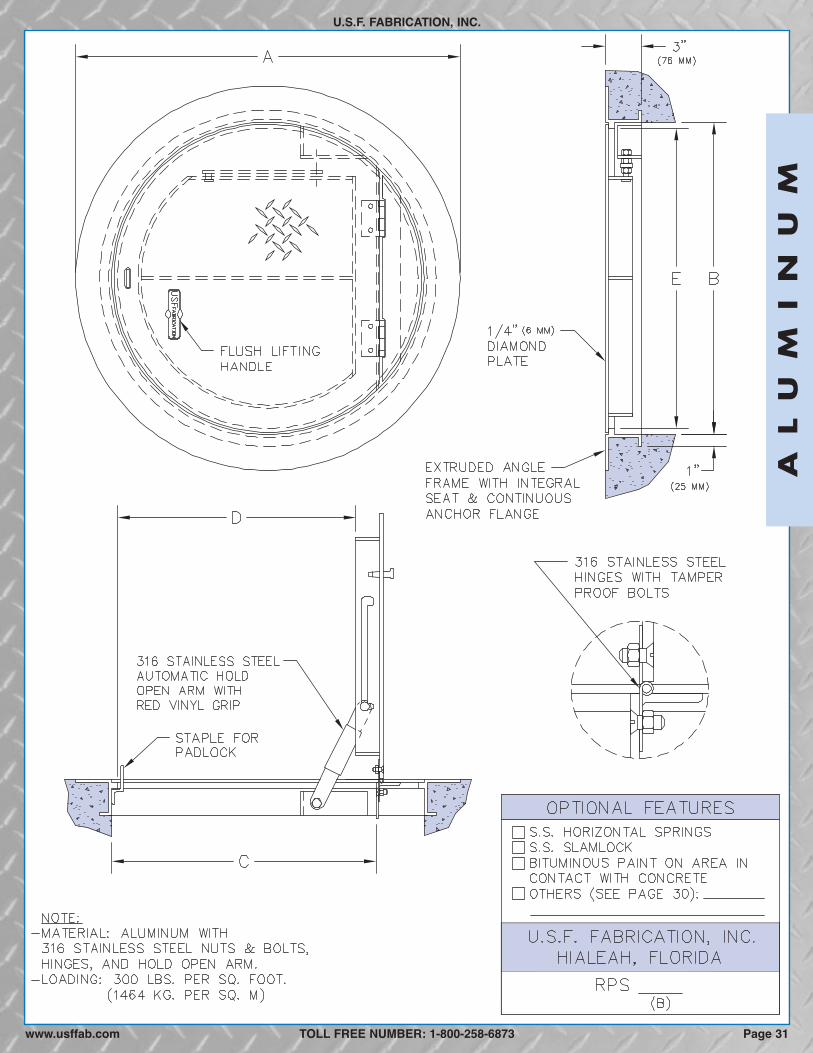
SPECIFICATIONS: The round floor access door shall be Model RPS as manufactured by U.S.F. Fabrication, Inc. with the size beingspecified on the plans. Door leaf shall be 1/4-inch thick aluminum diamond plate reinforced for a 300 p.s.f. live load. The frame shallbe extruded aluminum with an integral anchor flange and door seat. The floor access door shall be equipped with a flush liftinghandle that does not protrude above the cover, and a 316 stainless steel hold open arm with red vinyl grip that automatically keepsthe cover in its upright, open position. The door shall have 316 stainless steel hinges and 316 stainless steel tamper resistantbolts/locknuts. A staple for a padlock shall be supplied for security. An adhesive backed vinyl material that protects the productduring shipping and installation shall cover the entire top of the frame and cover. Installation shall be in accordance with themanufacturerʼs attached instructions. The door shall be manufactured and assembled in the United States. Manufacturer shallguarantee the door against defects in materials and workmanship for a period of ten years.
OPTIONAL FEATURES� Stainless steel horizontal springs for easy opening, see
page 81� 316 Stainless steel watertight slamlock and other
locking devices, see page 78� Bituminous coating on frame surface in contact with
concrete, see page 80� Cushion for noise dampening, see page 79� Nut rails with stainless steel sliding nuts for attaching
cable holders, brackets & other hardware, see page 85
� Fiberglass insulation with metal liner, see page 80� Custom lettering, see page 79� Anodized finish, see page 80� Hatch Safety Net, Fall Through Prevention System, see
pages 82-83� Holes for vents, pipe couplings and other hardware� Slip resistant surface bonded to cover plate, see page 80� All steel or stainless steel material� Reading Lid, see page 76
300 P.S.F. LOADING
MODELCOVER O.D. STRUCTURE I.D. OPENING CLEAR OPENING** WEIGHT*
RPS 1/4 (6) 78 (1981) 72 (1829) 48 (1219) 43 (1092) 71 (1803) 180 (82)RPS 1/4 (6) 66 (1676) 60 (1524) 40 (1016) 36 (914) 59 (1499) 135 (61)RPS 1/4 (6) 54 (1372) 48 (1219) 32 (813) 30 (762) 47 (1194) 95 (43)
in. (mm) A in. (mm) B in. (mm) C in. (mm) Lbs. (KG)D in. (mm) E in. (mm)COVER THK
* Weight shown is of our standard hatch only, and does not include any optional features. **Also referred to as "Actual Opening”which can vary to suit application.
CUSTOM SIZES READILY AVAILABLE
TOLL FREE NUMBER: 1-800-258-6873
AL
UM
IN
UM
www.usffab.comPage 30
We reserve the right to modify specifications and drawings without prior notice.
AL
UM
IN
UM
U.S.F. FABRICATION, INC.
TOLL FREE NUMBER: 1-800-258-6873 Page 31www.usffab.com
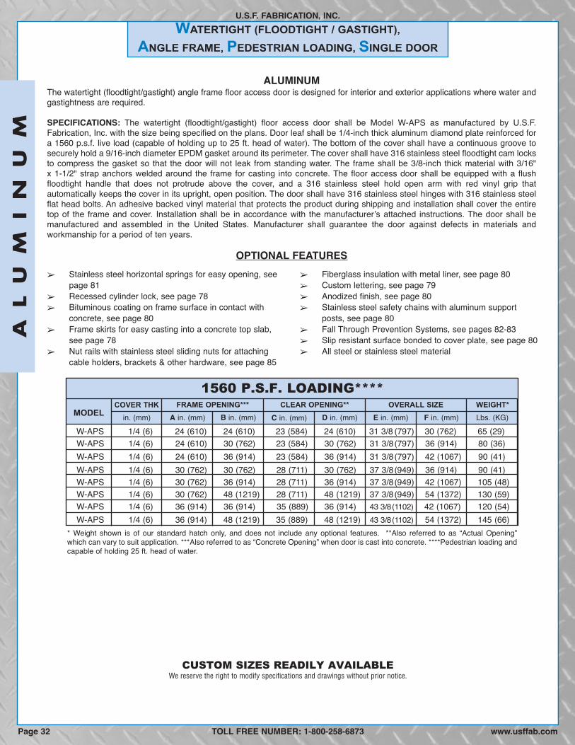
WATERTIGHT (FLOODTIGHT / GASTIGHT),
ANGLE FRAME, PEDESTRIAN LOADING, SINGLE DOOR
U.S.F. FABRICATION, INC.
ALUMINUMThe watertight (floodtight/gastight) angle frame floor access door is designed for interior and exterior applications where water andgastightness are required.
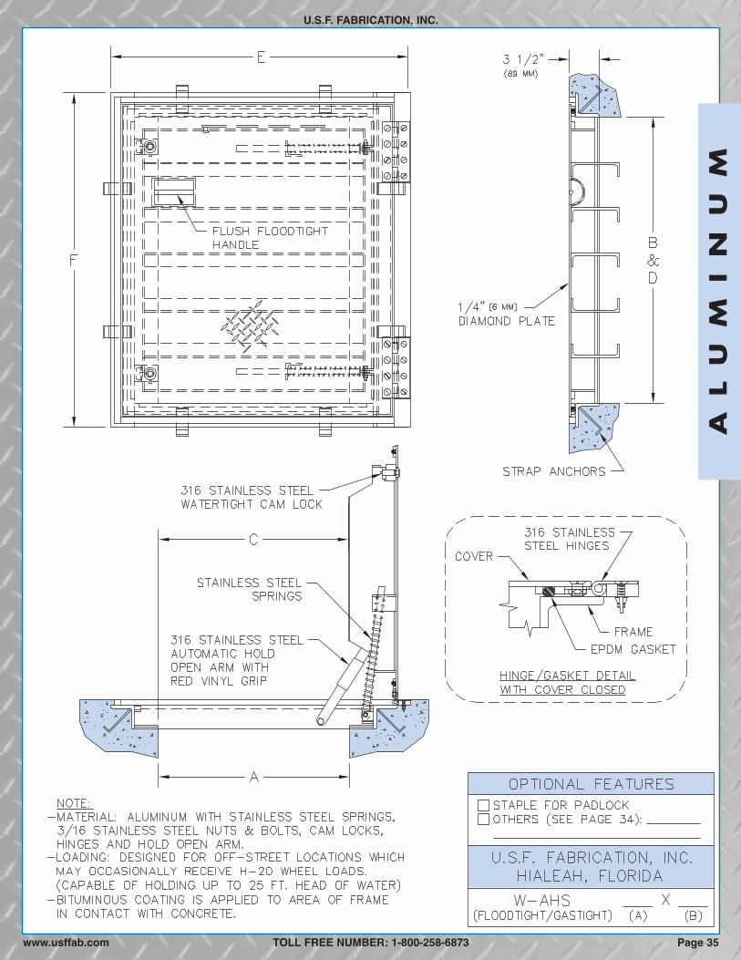
SPECIFICATIONS: The watertight (floodtight/gastight) floor access door shall be Model W-APS as manufactured by U.S.F.Fabrication, Inc. with the size being specified on the plans. Door leaf shall be 1/4-inch thick aluminum diamond plate reinforced fora 1560 p.s.f. live load (capable of holding up to 25 ft. head of water). The bottom of the cover shall have a continuous groove tosecurely hold a 9/16-inch diameter EPDM gasket around its perimeter. The cover shall have 316 stainless steel floodtight cam locksto compress the gasket so that the door will not leak from standing water. The frame shall be 3/8-inch thick material with 3/16"x 1-1/2" strap anchors welded around the frame for casting into concrete. The floor access door shall be equipped with a flushfloodtight handle that does not protrude above the cover, and a 316 stainless steel hold open arm with red vinyl grip thatautomatically keeps the cover in its upright, open position. The door shall have 316 stainless steel hinges with 316 stainless steelflat head bolts. An adhesive backed vinyl material that protects the product during shipping and installation shall cover the entiretop of the frame and cover. Installation shall be in accordance with the manufacturerʼs attached instructions. The door shall bemanufactured and assembled in the United States. Manufacturer shall guarantee the door against defects in materials andworkmanship for a period of ten years.
OPTIONAL FEATURES
1560 P.S.F. LOADING****
MODELFRAME OPENING*** CLEAR OPENING** OVERALL SIZE WEIGHT*
W-APS 1/4 (6) 24 (610) 24 (610) 23 (584) 24 (610) 31 3/8 (797) 30 (762) 65 (29)W-APS 1/4 (6) 24 (610) 30 (762) 23 (584) 30 (762) 31 3/8(797) 36 (914) 80 (36)W-APS 1/4 (6) 24 (610) 36 (914) 23 (584) 36 (914) 31 3/8(797) 42 (1067) 90 (41)W-APS 1/4 (6) 30 (762) 30 (762) 28 (711) 30 (762) 37 3/8(949) 36 (914) 90 (41)W-APS 1/4 (6) 30 (762) 36 (914) 28 (711) 36 (914) 37 3/8(949) 42 (1067) 105 (48)W-APS 1/4 (6) 30 (762) 48 (1219) 28 (711) 48 (1219) 37 3/8(949) 54 (1372) 130 (59)W-APS 1/4 (6) 36 (914) 36 (914) 35 (889) 36 (914) 43 3/8(1102) 42 (1067) 120 (54)W-APS 1/4 (6) 36 (914) 48 (1219) 35 (889) 48 (1219) 43 3/8(1102) 54 (1372) 145 (66)
in. (mm) A in. (mm) B in. (mm) C in. (mm) F in. (mm)D in. (mm) E in. (mm) Lbs. (KG)COVER THK
� Stainless steel horizontal springs for easy opening, seepage 81
� Recessed cylinder lock, see page 78� Bituminous coating on frame surface in contact with
concrete, see page 80� Frame skirts for easy casting into a concrete top slab,
see page 78� Nut rails with stainless steel sliding nuts for attaching
cable holders, brackets & other hardware, see page 85
� Fiberglass insulation with metal liner, see page 80� Custom lettering, see page 79� Anodized finish, see page 80� Stainless steel safety chains with aluminum support
posts, see page 80� Fall Through Prevention Systems, see pages 82-83� Slip resistant surface bonded to cover plate, see page 80� All steel or stainless steel material
* Weight shown is of our standard hatch only, and does not include any optional features. **Also referred to as “Actual Opening”which can vary to suit application. ***Also referred to as “Concrete Opening” when door is cast into concrete. ****Pedestrian loading andcapable of holding 25 ft. head of water.
CUSTOM SIZES READILY AVAILABLE
TOLL FREE NUMBER: 1-800-258-6873
AL
UM
IN
UM
www.usffab.comPage 32
We reserve the right to modify specifications and drawings without prior notice.

AL
UM
IN
UM
U.S.F. FABRICATION, INC.
TOLL FREE NUMBER: 1-800-258-6873www.usffab.com Page 33

U.S.F. FABRICATION, INC.
ALUMINUMThe heavy-duty watertight (floodtight/gastight) angle frame floor access door is designed for interior and exterior applications wherewater and gastightness are required. It is designed for off-street locations that may occasionally receive AASHTO H-20-44 wheelloads.
SPECIFICATIONS: The watertight (floodtight/gastight) floor access door shall be Model W-AHS as manufactured by U.S.F.Fabrication, Inc. with the size being specified on the plans. Door leaf shall be 1/4-inch thick aluminum diamond plate reinforced foran AASHTO H-20-44 wheel load (capable of holding up to 25 ft. head of water). Upon request, manufacturer shall provide structuralcalculations showing that the door design meets the loading requirements of AASHTO H20-44. (The floor access door is designedfor off-street locations that may occasionally receive AASHTO H-20 wheel loads.) The bottom of the cover shall have a continuousgroove to securely hold a 9/16-inch diameter EPDM gasket around its perimeter. The cover shall have 316 stainless steel floodtightcam locks to compress the gasket so that the door will not leak from standing water. The frame shall be 3/8-inch thick material with3/16" x 1-1/2" strap anchors welded around the frame for casting into concrete. The floor access door shall be equipped with a flushfloodtight handle that does not protrude above the cover, and a 316 stainless steel hold open arm with red vinyl grip that automaticallykeeps the cover in its upright, open position. The door shall have 316 stainless steel hinges with 316 stainless steel flat head bolts.The door shall have stainless steel open horizontal springs to assist in opening the cover and reducing the force during closing.Installation shall be in accordance with the manufacturerʼs attached instructions. The entire frame including the seat on which thereinforcing rests shall be supported by concrete or other material designed to support the specified load. All parts of the frame incontact with concrete shall have a coating of bituminous paint. An adhesive backed vinyl material that protects the product duringshipping and installation shall cover the entire top of the frame and cover. The door shall be manufactured and assembled in theUnited States. Manufacturer shall guarantee the door against defects in materials and workmanship for a period of ten years.
OPTIONAL FEATURES
H-20 LOADING****
MODELFRAME OPENING*** CLEAR OPENING** OVERALL SIZE WEIGHT*
W-AHS 1/4 (6) 24 (610) 24 (610) 24 (610) 24 (610) 37 3/8 (949) 30 (762) 84 (38)W-AHS 1/4 (6) 24 (610) 30 (762) 24 (610) 30 (762) 37 3/8 (949) 36 (914) 101 (46)W-AHS 1/4 (6) 24 (610) 36 (914) 24 (610) 36 (914) 37 3/8 (949) 42 (1067) 117 (53)W-AHS 1/4 (6) 30 (762) 30 (762) 30 (762) 30 (762) 43 3/8(1102) 36 (914) 125 (57)W-AHS 1/4 (6) 30 (762) 36 (914) 30 (762) 36 (914) 43 3/8(1102) 42 (1067) 136 (62)W-AHS 1/4 (6) 30 (762) 48 (1219) 30 (762) 48 (1219) 43 3/8(1102) 54 (1372) 176 (80)W-AHS 1/4 (6) 36 (914) 36 (914) 36 (914) 36 (914) 49 3/8(1254) 42 (1067) 156 (71)W-AHS 1/4 (6) 36 (914) 48 (1219) 36 (914) 48 (1219) 49 3/8(1254) 54 (1372) 201 (91)
in. (mm) A in. (mm) B in. (mm) C in. (mm) F in. (mm)D in. (mm) E in. (mm) Lbs. (KG)COVER THK
� Enclosed, stainless steel horizontal springs for easyopening, see page 81
� Recessed cylinder lock, see page 78� Frame skirts for easy casting into a concrete top slab,
see page 78� Nut rails with stainless steel sliding nuts for attaching
cable holders, brackets & other hardware, see page 85� Fiberglass insulation with metal liner, see page 80
� Custom lettering, see page 79� Anodized finish, see page 80� Stainless steel safety chains with aluminum support
posts, see page 80� Fall Through Prevention Systems, see pages 82-83� Slip resistant surface bonded to cover plate, see page 80� All steel or stainless steel material
WATERTIGHT (FLOODTIGHT / GASTIGHT),
ANGLE FRAME, HEAVY-DUTY, SINGLE DOOR
*Weight shown is of our standard hatch only, and does not include any optional features. **Also referred to as “Actual Opening”which can vary to suit application. ***Also referred to as “Concrete Opening” when door is cast into concrete. **** W-AHS aluminumfloor access doors are intended for off-street locations that may occasionally receive AASHTO H-20 wheel loads (16,000 lbs. over 10”x 20” area + 30% impact factor), and capable of holding 25 ft. head of water. Call Customer Service for direct traffic applications.
CUSTOM SIZES READILY AVAILABLE
TOLL FREE NUMBER: 1-800-258-6873
AL
UM
IN
UM
www.usffab.comPage 34
We reserve the right to modify specifications and drawings without prior notice.
AL
UM
IN
UM
U.S.F. FABRICATION, INC.
TOLL FREE NUMBER: 1-800-258-6873 Page 35www.usffab.com
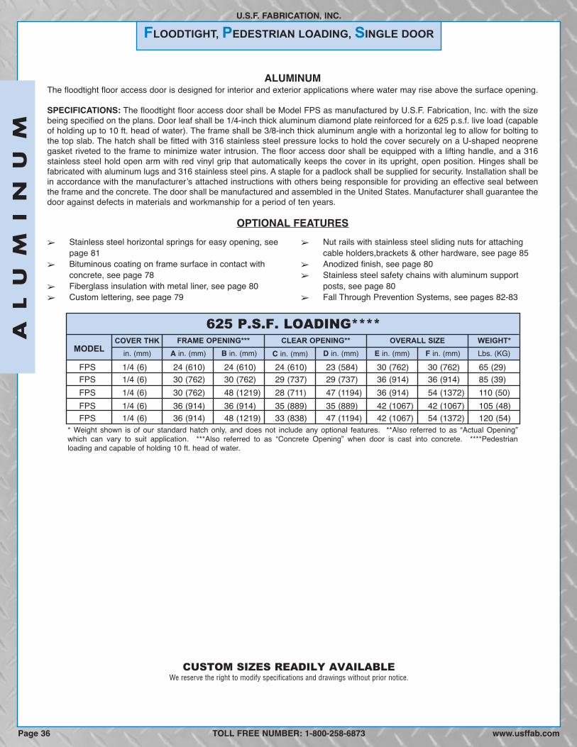
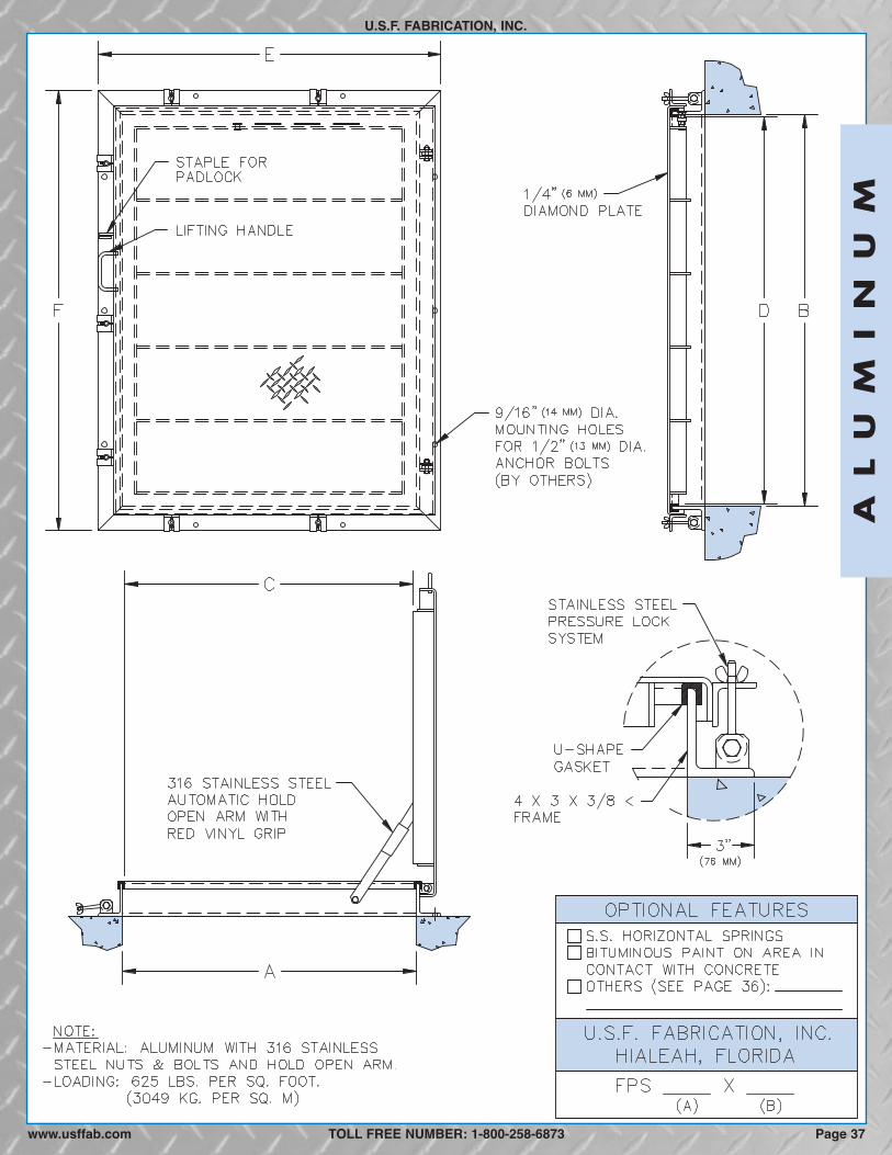
FLOODTIGHT, PEDESTRIAN LOADING, SINGLE DOOR
U.S.F. FABRICATION, INC.
625 P.S.F. LOADING****
MODELFRAME OPENING*** CLEAR OPENING** OVERALL SIZE WEIGHT*
FPS 1/4 (6) 24 (610) 24 (610) 24 (610) 23 (584) 30 (762) 30 (762) 65 (29)FPS 1/4 (6) 30 (762) 30 (762) 29 (737) 29 (737) 36 (914) 36 (914) 85 (39)FPS 1/4 (6) 30 (762) 48 (1219) 28 (711) 47 (1194) 36 (914) 54 (1372) 110 (50)FPS 1/4 (6) 36 (914) 36 (914) 35 (889) 35 (889) 42 (1067) 42 (1067) 105 (48)FPS 1/4 (6) 36 (914) 48 (1219) 33 (838) 47 (1194) 42 (1067) 54 (1372) 120 (54)
in. (mm) A in. (mm) B in. (mm) C in. (mm) F in. (mm)D in. (mm) E in. (mm) Lbs. (KG)COVER THK
� Stainless steel horizontal springs for easy opening, seepage 81
� Bituminous coating on frame surface in contact withconcrete, see page 78
� Fiberglass insulation with metal liner, see page 80� Custom lettering, see page 79
� Nut rails with stainless steel sliding nuts for attachingcable holders,brackets & other hardware, see page 85
� Anodized finish, see page 80� Stainless steel safety chains with aluminum support
posts, see page 80� Fall Through Prevention Systems, see pages 82-83
* Weight shown is of our standard hatch only, and does not include any optional features. **Also referred to as “Actual Opening”which can vary to suit application. ***Also referred to as “Concrete Opening” when door is cast into concrete. ****Pedestrianloading and capable of holding 10 ft. head of water.
CUSTOM SIZES READILY AVAILABLE
TOLL FREE NUMBER: 1-800-258-6873
AL
UM
IN
UM
ALUMINUMThe floodtight floor access door is designed for interior and exterior applications where water may rise above the surface opening.
SPECIFICATIONS: The floodtight floor access door shall be Model FPS as manufactured by U.S.F. Fabrication, Inc. with the sizebeing specified on the plans. Door leaf shall be 1/4-inch thick aluminum diamond plate reinforced for a 625 p.s.f. live load (capableof holding up to 10 ft. head of water). The frame shall be 3/8-inch thick aluminum angle with a horizontal leg to allow for bolting tothe top slab. The hatch shall be fitted with 316 stainless steel pressure locks to hold the cover securely on a U-shaped neoprenegasket riveted to the frame to minimize water intrusion. The floor access door shall be equipped with a lifting handle, and a 316stainless steel hold open arm with red vinyl grip that automatically keeps the cover in its upright, open position. Hinges shall befabricated with aluminum lugs and 316 stainless steel pins. A staple for a padlock shall be supplied for security. Installation shall bein accordance with the manufacturerʼs attached instructions with others being responsible for providing an effective seal betweenthe frame and the concrete. The door shall be manufactured and assembled in the United States. Manufacturer shall guarantee thedoor against defects in materials and workmanship for a period of ten years.
OPTIONAL FEATURES
www.usffab.comPage 36
We reserve the right to modify specifications and drawings without prior notice.
AL
UM
IN
UM
U.S.F. FABRICATION, INC.
TOLL FREE NUMBER: 1-800-258-6873www.usffab.com Page 37

RECESSED
ANGLE FRAME, PEDESTRIAN LOADING, SINGLE DOOR
U.S.F. FABRICATION, INC.
ALUMINUMThe recessed angle frame floor access door is designed for interior and exterior applications where watertightness is not required.It has a 1/8-inch recess to receive tile or carpet.
SPECIFICATIONS: The recessed floor access door shall be Model R-APS as manufactured by U.S.F. Fabrication, Inc. with the sizebeing specified on the plans. Door leaf shall be 1/4-inch thick aluminum smooth plate reinforced for a 150 p.s.f. live load; and, havea 1/8-inch recess to receive tile or carpet. Both cover and frame shall have a metal lip around the entire perimeter defining therecess. The frame shall be extruded aluminum with an integral door seat on all four sides which has a groove to receive a cushionfor noise dampening. The floor access door shall be equipped with a 316 stainless steel hold open arm with red vinyl grip thatautomatically keeps the cover in its upright, open position. The door shall have hinges that are not visible when the door is closed.The door shall have 316 stainless steel torsion bars to assist in opening the door and reducing the force during closing. The doorshall be equipped with a watertight 316 stainless steel slamlock with threaded plug, removable outside key, and fixed inside han-dle. The slamlock latches onto a 316 stainless steel striker plate that is bolted to the frame. All parts of the frame in contact withconcrete shall have a coating of bituminous paint. Installation shall be in accordance with the manufacturerʼs attached instructions.The door shall be manufactured and assembled in the United States. Manufacturer shall guarantee the door against defects inmaterials and workmanship for a period of ten years.
OPTIONAL FEATURES� Recessed cylinder lock, see page 78� Frame skirts for easy casting into a concrete top slab, see
page 78� Nut rails with stainless steel sliding nuts for attaching
cable holders, brackets & other hardware, see page 85� Anodized finish, see page 80
� Fiberglass insulation with metal liner, see page 80� Stainless steel safety chains with aluminum support
posts, see page 80� Fall Through Prevention Systems, see pages 82-83� Double door cover
CUSTOM SIZES READILY AVAILABLE
TOLL FREE NUMBER: 1-800-258-6873
150 P.S.F. LOADING
MODELFRAME OPENING*** COVER RECESS** OVERALL SIZE WEIGHT*
R-APS 1/4 (6) 26 1/8 (664) 22 3/4 (578) 24 (610) 24 (610) 31 1/8 (791) 28 3/4 (730) 45 (20)R-APS 1/4 (6) 26 1/8 (664) 28 3/4 (730) 24 (610) 30 (762) 31 1/8 (791) 34 3/4 (883) 50 (23)R-APS 1/4 (6) 26 1/8 (664) 34 3/4 (883) 24 (610) 36 (914) 31 1/8 (791) 40 3/4 (1035) 60 (27)R-APS 1/4 (6) 32 1/8 (816) 28 3/4 (730) 30 (762) 30 (762) 37 1/8 (943) 34 3/4 (883) 60 (27)R-APS 1/4 (6) 32 1/8 (816) 34 3/4 (883) 30 (762) 36 (914) 37 1/8 (943) 40 3/4 (1035) 70 (32)R-APS 1/4 (6) 32 1/8 (816) 46 3/4 (1187) 30 (762) 48 (1219) 37 1/8 (943) 52 3/4 (1340) 85 (39)R-APS 1/4 (6) 38 1/8 (968) 34 3/4 (883) 36 (914) 36 (914) 43 1/8 (1095) 40 3/4 (1035) 75 (34)R-APS 1/4 (6) 38 1/8 (968) 46 3/4 (1187) 36 (914) 48 (1219) 43 1/8 (1095) 52 3/4 (1340) 95 (43)R-APS 1/4 (6) 44 1/8 (1121) 40 3/4 (1035) 42 (1067) 42 (1067) 49 1/8 (1248) 46 3/4 (1187) 95 (43)
in. (mm) A in. (mm) B in. (mm) C in. (mm) F in. (mm)D in. (mm) E in. (mm) Lbs. (KG)COVER THK
*Weight shown is of our standard hatch only, and does not include any optional features. **Dimensions of recessed area in the cover that receivethe tile. ***Also referred to as “Concrete Opening” when door is cast into concrete.
AL
UM
IN
UM
www.usffab.comPage 38
We reserve the right to modify specifications and drawings without prior notice.

AL
UM
IN
UM
U.S.F. FABRICATION, INC.
TOLL FREE NUMBER: 1-800-258-6873 Page 39www.usffab.com

RECESSED
TROUGH, PEDESTRIAN LOADING, SINGLE DOOR
U.S.F. FABRICATION, INC.
ALUMINUMThe recessed trough frame floor access door with drainable frame is designed for interior and exterior applications where dirt andwater are to be prevented from falling into the area below. The cover has a 1-inch recess to receive tile or concrete.
SPECIFICATIONS: The recessed floor access door shall be Model R-TPS as manufactured by U.S.F. Fabrication, Inc. with the sizebeing specified on the plans. Door leaf shall be 1/4-inch thick aluminum smooth plate reinforced for a 300 p.s.f. live load; and, havea 1-inch recess to receive tile or concrete. If recess is to be filled with concrete or other cast material, the door is furnished with anchorclips and wire mesh. Both the cover and frame shall have a metal lip around the entire perimeter defining the recess. The troughframe shall be fabricated from 1/4-inch aluminum and shall have an anchor flange on all four sides. The frame shall drain water outthrough a 1 1/2-inch pipe coupling. The floor access door shall be equipped with a flush aluminum lifting handle that does notprotrude above the cover and, a 316 stainless steel hold open arm with red vinyl grip that automatically keeps the cover in its upright,open position. The door shall have a continuous 316 stainless steel hinge that is flush with the top of the cover. The door shall havestainless steel vertical compression springs to assist in opening the door and reducing the force during closing. The door shallbe equipped with a watertight 316 stainless steel slamlock with threaded plug, removable outside key, and fixed inside handle. Theslamlock latches onto a 316 stainless steel striker plate that is bolted to the frame. All parts of the frame in contact with concrete shallhave a coating of bituminous paint. Installation shall be in accordance with the manufacturerʼs attached instructions. The doorshall be manufactured and assembled in the United States. Manufacturer shall guarantee the door against defects in materials andworkmanship for a period of ten years.
OPTIONAL FEATURES
300 P.S.F. LOADING
MODELFRAME OPENING*** CLEAR OPENING** OVERALL SIZE WEIGHT*
R-TPS 1/4 (6) 24 (610) 24 (610) 23 (584) 24 (610) 32 (813) 32 (813) 80 (36)R-TPS 1/4 (6) 24 (610) 30 (762) 23 (584) 30 (762) 32 (813) 38 (965) 90 (41)R-TPS 1/4 (6) 24 (610) 36 (914) 23 (584) 36 (914) 32 (813) 44 (1118) 100 (45)R-TPS 1/4 (6) 30 (762) 30 (762) 28 (711) 30 (762) 38 (965) 38 (965) 105 (48)R-TPS 1/4 (6) 30 (762) 36 (914) 28 (711) 36 (914) 38 (965) 44 (1118) 115 (52)R-TPS 1/4 (6) 30 (762) 48 (1219) 28 (711) 48 (1219) 38 (965) 56 (1422) 140 (64)R-TPS 1/4 (6) 36 (914) 36 (914) 34 (864) 36 (914) 44 (1118) 44 (1118) 135 (61)
in. (mm) A in. (mm) B in. (mm) C in. (mm) F in. (mm)D in. (mm) E in. (mm) Lbs. (KG)COVER THK
� Recessed cylinder lock, see page 78� Frame skirts for easy casting into a concrete top slab,
see page 78� Nut rails with stainless steel sliding nuts for attaching
cable holders, brackets & other hardware, see page 85� Fiberglass insulation with metal liner, see page 80� Anodized finish, see page 80
� Stainless steel safety chains with aluminum suppot posts,see page 80
� Fall Through Prevention Systems, see pages 82-83� Side drain coupling (instead of standard bottom drain)� Double door cover� Adjust springs for wood or tile fill in recess area
* Weight shown is of our standard hatch only, and does not include any optional features. **Also referred to as “Actual Opening”which can vary to suit application. ***Also referred to as “Concrete Opening” when door is cast into concrete.
CUSTOM SIZES READILY AVAILABLE
TOLL FREE NUMBER: 1-800-258-6873
AL
UM
IN
UM
www.usffab.comPage 40
We reserve the right to modify specifications and drawings without prior notice.

AL
UM
IN
UM
U.S.F. FABRICATION, INC.
TOLL FREE NUMBER: 1-800-258-6873 Page 41www.usffab.com

SECURITY RESERVOIR & ROOF INTERNAL MOUNTING FLANGE
U.S.F. FABRICATION, INC.
ALUMINUMThe SRR-I angle frame access door is designed for exterior applications where dirt and water are to be prevented from falling intothe area below.
SPECIFICATIONS: The security reservoir & roof door shall be Model SRR-I as manufactured by U.S.F. Fabrication, Inc. with thesize being specified on the plans. Door leaf shall be 3/16-inch thick aluminum diamond plate reinforced for 150 p.s.f. live load. Theframe shall be 3/16-inch aluminum structural angle with 7/16-inch diameter holes for bolting to curb or roof deck and have anextruded U-shaped EDPM rubber weatherseal gasket where the cover closes on the frame. The access door shall be equipped witha 316 stainless steel slamlock with fixed exterior and interior handles and interior padlock staple. A 316 stainless steel hold openarm with push/pull handle shall automatically keep the cover in its upright, open position. The door shall have a mill finish and hingesfabricated with aluminum lugs and 316 stainless steel pins. The door shall have stainless steel horizontal compression springs toassist in opening the door and reducing the force during closing. Installation shall be in accordance with the manufacturerʼs attachedinstructions with others being responsible for providing an effective seal between the frame and the mounting surface. The doorshall be manufactured and assembled in the United States. Manufacturer shall guarantee the door against defects in materials andworkmanship for a period of ten years.
OPTIONAL FEATURES
150 P.S.F. LOADING
MODELFRAME OPENING CLEAR OPENING** OVERALL SIZE WEIGHT*
SRR-I 3/16 (5) 24 (610) 24 (610) 24 (610) 24 (610) 32 5/8 (829) 31 5/8 (803) 60 (27)
44 5/8 (1133) 37 5/8 (956) 80 (36)44 5/8 (1133) 43 5/8 (1108) 85 (39)50 5/8 (1286) 49 5/8 (1260) 100 (45)
SRR-I 3/16 (5) 30 (762) 30 (762) 30 (762) 30 (762)
In. (mm) A in. (mm) B in. (mm) C in. (mm) F in. (mm)D in. (mm) E in. (mm) Lbs. (KG)COVER THK
� 3/16-inch thick aluminum smooth plate cover� Exterior padlock staple� Removable exterior slamlock handle with choice of slotted
plug or tamper resistant plug� Cylinder deadbolt lock keyed exterior, interior or both
� Indicator switch to signal when cover is not fully closed� Anodized finish, see page 80� Stainless steel safety chains with aluminum support
posts, see page 80� Custom lettering, see page 79
Page 42 www.usffab.com
CUSTOM SIZES READILY AVAILABLE
TOLL FREE NUMBER: 1-800-258-6873
AL
UM
IN
UM
We reserve the right to modify specifications and drawings without prior notice.
* Weight shown is of our standard hatch only, and does not include any optional features. **Also referred to as “Actual Opening”which can vary to suit application.
SRR-I 3/16 (5) 48 (1219) 48 (1219) 48 (1219) 48 (1219)SRR-I 3/16 (5) 42 (1067) 42 (1067) 42 (1067) 42 (1067)SRR-I 3/16 (5) 36 (914) 36 (914) 36 (914) 36 (914)SRR-I 3/16 (5) 36 (914) 30 (762) 36 (914) 30 (762)
56 5/8 (1438) 55 5/8 (1413) 120 (54)
SRR-I 3/16 (5) 30 (762) 54 (1372) 30 (762) 54 (1372) 38 5/8 (981) 61 5/8 (1565) 125 (57)38 5/8 (981) 37 5/8 (956) 70 (32)
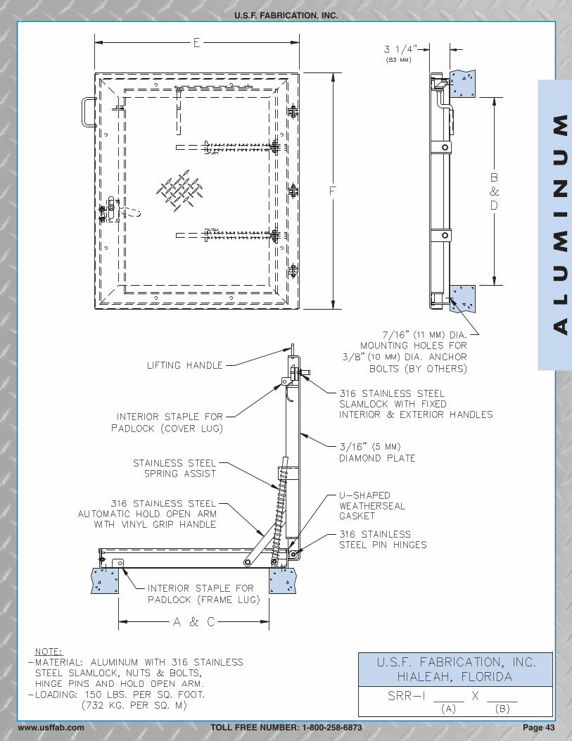
Page 43www.usffab.com
AL
UM
IN
UM
U.S.F. FABRICATION, INC.
TOLL FREE NUMBER: 1-800-258-6873
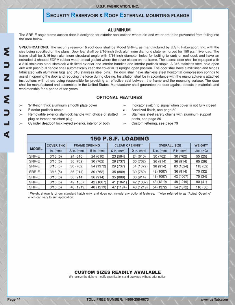
SECURITY RESERVOIR & ROOF EXTERNAL MOUNTING FLANGE
U.S.F. FABRICATION, INC.
ALUMINUMThe SRR-E angle frame access door is designed for exterior applications where dirt and water are to be prevented from falling intothe area below.
SPECIFICATIONS: The security reservoir & roof door shall be Model SRR-E as manufactured by U.S.F. Fabrication, Inc. with thesize being specified on the plans. Door leaf shall be 3/16-inch thick aluminum diamond plate reinforced for 150 p.s.f. live load. Theframe shall be 3/16-inch aluminum structural angle with 7/16-inch diameter holes for bolting to curb or roof deck and have anextruded U-shaped EDPM rubber weatherseal gasket where the cover closes on the frame. The access door shall be equipped witha 316 stainless steel slamlock with fixed exterior and interior handles and interior padlock staple. A 316 stainless steel hold openarm with push/pull handle shall automatically keep the cover in its upright, open position. The door shall have a mill finish and hingesfabricated with aluminum lugs and 316 stainless steel pins. The door shall have stainless steel horizontal compression springs toassist in opening the door and reducing the force during closing. Installation shall be in accordance with the manufacturerʼs attachedinstructions with others being responsible for providing an effective seal between the frame and the mounting surface. The doorshall be manufactured and assembled in the United States. Manufacturer shall guarantee the door against defects in materials andworkmanship for a period of ten years.
OPTIONAL FEATURES� 3/16-inch thick aluminum smooth plate cover� Exterior padlock staple� Removable exterior slamlock handle with choice of slotted
plug or tamper resistant plug� Cylinder deadbolt lock keyed exterior, interior or both
� Indicator switch to signal when cover is not fully closed� Anodized finish, see page 80� Stainless steel safety chains with aluminum support
posts, see page 80� Custom lettering, see page 79
Page 44 www.usffab.com
CUSTOM SIZES READILY AVAILABLE
TOLL FREE NUMBER: 1-800-258-6873
AL
UM
IN
UM
We reserve the right to modify specifications and drawings without prior notice.
150 P.S.F. LOADING
MODELFRAME OPENING CLEAR OPENING** OVERALL SIZE WEIGHT*
SRR-E 3/16 (5) 24 (610) 24 (610) 23 (584) 24 (610) 30 (762) 30 (762) 55 (25)36 (914) 36 (914) 65 (29)
42 (1067) 36 (914) 70 (32)42 (1067) 42 (1067) 75 (34)48 (1219) 48 (1219) 90 (41)54 (1372) 54 (1372) 110 (50)
36 (914) 60 (1524) 115 (52)SRR-E 3/16 (5) 30 (762) 30 (762) 29 (737) 30 (762)
SRR-E 3/16 (5) 36 (914) 30 (762) 35 (889) 30 (762)SRR-E 3/16 (5) 36 (914) 36 (914) 35 (889) 36 (914)SRR-E 3/16 (5) 42 (1067) 42 (1067) 41 (1041) 42 (1067)
SRR-E 3/16 (5) 30 (762) 54 (1372) 29 (737) 54 (1372)
SRR-E 3/16 (5) 48 (1219) 48 (1219) 47 (1194) 48 (1219)
In. (mm) A in. (mm) B in. (mm) C in. (mm) F in. (mm)D in. (mm) E in. (mm) Lbs. (KG)COVER THK
* Weight shown is of our standard hatch only, and does not include any optional features. **Also referred to as “Actual Opening”which can vary to suit application.

Page 45www.usffab.com
AL
UM
IN
UM
U.S.F. FABRICATION, INC.
TOLL FREE NUMBER: 1-800-258-6873
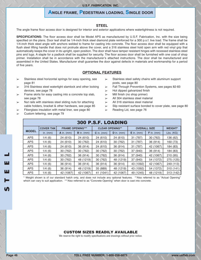
ANGLE FRAME, PEDESTRIAN LOADING, SINGLE DOOR
U.S.F. FABRICATION, INC.
STEELThe angle frame floor access door is designed for interior and exterior applications where watertightness is not required.
SPECIFICATIONS: The floor access door shall be Model APS as manufactured by U.S.F. Fabrication, Inc. with the size beingspecified on the plans. Door leaf shall be 1/4-inch thick steel diamond plate reinforced for a 300 p.s.f. live load. The frame shall be1/4-inch thick steel angle with anchors welded to frame for casting into concrete. The floor access door shall be equipped with aflush steel lifting handle that does not protrude above the cover, and a 316 stainless steel hold open arm with red vinyl grip thatautomatically keeps the cover in its upright, open position. The door shall have tamper resistant hinges with recessed stainless steelpins and lugs. A staple for a padlock shall be supplied for security. The floor access door shall be furnished with one coat of shopprimer. Installation shall be in accordance with the manufacturerʼs attached instructions. The door shall be manufactured andassembled in the United States. Manufacturer shall guarantee the door against defects in materials and workmanship for a periodof five years.
OPTIONAL FEATURES
300 P.S.F. LOADING
MODELFRAME OPENING*** CLEAR OPENING** OVERALL SIZE WEIGHT*
APS 1/4 (6) 24 (610) 24 (610) 24 (610) 24 (610) 31 (787) 30 (762) 136 (62)APS 1/4 (6) 24 (610) 30 (762) 24 (610) 30 (762) 31 (787) 36 (914) 160 (73)APS 1/4 (6) 24 (610) 36 (914) 24 (610) 36 (914) 31 (787) 42 (1067) 184 (83)APS 1/4 (6) 30 (762) 30 (762) 30 (762) 30 (762) 37 (940) 36 (914) 184 (83)APS 1/4 (6) 30 (762) 36 (914) 30 (762) 36 (914) 37 (940) 42 (1067) 210 (95)APS 1/4 (6) 30 (762) 48 (1219) 30 (762) 48 (1219) 37 (940) 54 (1372) 275 (125)APS 1/4 (6) 36 (914) 36 (914) 36 (914) 36 (914) 43 (1092) 42 (1067) 249 (113)APS 1/4 (6) 36 (914) 48 (1219) 35 (889) 48 (1219) 43 (1092) 54 (1372) 310 (141)APS 1/4 (6) 42 (1067) 42 (1067) 41 (1041) 42 (1067) 49 (1245) 48 (1219) 313 (142)
in. (mm) A in. (mm) B in. (mm) C in. (mm) F in. (mm)D in. (mm) E in. (mm) Lbs. (KG)COVER THK
� Stainless steel horizontal springs for easy opening, seepage 81
� 316 Stainless steel watertight slamlock and other lockingdevices, see page 78
� Frame skirts for easy casting into a concrete top slab,see page 78
� Nut rails with stainless steel sliding nuts for attachingcable holders, bracket & other hardware, see page 85
� Fiberglass insulation with metal liner, see page 80� Custom lettering, see page 79
� Stainless steel safety chains with aluminum supportposts, see page 80
� Fall Through Prevention Systems, see pages 82-83� Hot dipped galvanized finish� Mill finish (no shop primer)� All 304 stainless steel material� All 316 stainless steel material� Slip resistant surface bonded to cover plate, see page 80� Reading Lid, see page 76
* Weight shown is of our standard hatch only, and does not include any optional features. **Also referred to as “Actual Opening”which can vary to suit application. ***Also referred to as “Concrete Opening” when door is cast into concrete.
CUSTOM SIZES READILY AVAILABLE
TOLL FREE NUMBER: 1-800-258-6873
ST
EE
L
www.usffab.comPage 46
We reserve the right to modify specifications and drawings without prior notice.

ST
EE
L
U.S.F. FABRICATION, INC.
TOLL FREE NUMBER: 1-800-258-6873 Page 47www.usffab.com

ANGLE FRAME, PEDESTRIAN LOADING, DOUBLE DOOR
U.S.F. FABRICATION, INC.
STEELThe angle frame floor access door is designed for interior and exterior applications where watertightness is not required.
SPECIFICATIONS: The floor access door shall be Model APD as manufactured by U.S.F. Fabrication, Inc. with the size beingspecified on the plans. Door leaves shall be 1/4-inch thick steel diamond plate reinforced for a 300 p.s.f. live load. The frame shallbe 1/4-inch thick steel angle with anchors welded to frame for casting into concrete. The floor access door shall be equipped witha flush steel lifting handle that does not protrude above the cover, and 316 stainless steel hold open arms with red vinyl grips thatautomatically keep the covers in their upright, open positions. The door shall have tamper resistant hinges with recessed stainlesssteel pins and lugs. A staple for a padlock shall be supplied for security. The floor access door shall be furnished with one coat ofshop primer. Installation shall be in accordance with the manufacturerʼs attached instructions. The door shall be manufactured andassembled in the United States. Manufacturer shall guarantee the door against defects in materials and workmanship for a periodof five years.
OPTIONAL FEATURES
300 P.S.F. LOADING
MODELFRAME OPENING*** CLEAR OPENING** OVERALL SIZE WEIGHT*
APD 1/4 (6) 30 (762) 48 (1219) 29 (737) 48 (1219) 36 (914) 56 (1422) 281 (127)APD 1/4 (6) 30 (762) 54 (1372) 29 (737) 54 (1372) 36 (914) 62 (1575) 306 (139)APD 1/4 (6) 36 (914) 48 (1219) 35 (889) 48 (1219) 42 (1067) 56 (1422) 321 (146)APD 1/4 (6) 36 (914) 60 (1524) 35 (889) 60 (1524) 42 (1067) 68 (1727) 376 (171)APD 1/4 (6) 42 (1067) 48 (1219) 41 (1041) 48 (1219) 48 (1219) 56 (1422) 362 (164)APD 1/4 (6) 48 (1219) 48 (1219) 47 (1194) 48 (1219) 54 (1372) 56 (1422) 404 (183)APD 1/4 (6) 48 (1219) 54 (1372) 47 (1194) 53 (1346) 54 (1372) 62 (1575) 453 (205)
APD 1/4 (6) 60 (1524) 60 (1524) 59 (1499) 58 (1473) 66 (1676) 68 (1727) 591 (268)APD 1/4 (6) 48 (1219) 72 (1829) 47 (1194) 71 (1803) 54 (1372) 80 (2032) 565 (256)
in. (mm) A in. (mm) B in. (mm) C in. (mm) F in. (mm)D in. (mm) E in. (mm) Lbs. (KG)COVER THK
� Stainless steel horizontal springs for easy opening, seepage 81
� 316 Stainless steel watertight slamlock and otherlocking devices, see page 78
� Frame skirts for easy casting into a concrete top slab,see page 78
� Nut rails with stainless steel sliding nuts for attachingcable holders, bracket & other hardware, see page 85
� Fiberglass insulation with metal liner, see page 80� Custom lettering, see page 79
� Stainless steel safety chains, see page 80� Fall Through Prevention Systems, see pages 82-83� Hot dipped galvanized finish� Mill finish (no shop primer)� All 304 stainless steel material� All 316 stainless steel material� Slip resistant surface bonded to cover plate, see page 80� Hinge covers on same long side, see page 84� Reading Lid, see page 76
* Weight shown is of our standard hatch only, and does not include any optional features. **Also referred to as “Actual Opening”which can vary to suit application. ***Also referred to as “Concrete Opening” when door is cast into concrete.
CUSTOM SIZES READILY AVAILABLE
TOLL FREE NUMBER: 1-800-258-6873
ST
EE
L
Page 48 www.usffab.com
We reserve the right to modify specifications and drawings without prior notice.

ST
EE
L
U.S.F. FABRICATION, INC.
TOLL FREE NUMBER: 1-800-258-6873 Page 49www.usffab.com
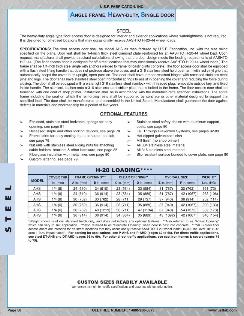
ANGLE FRAME, HEAVY-DUTY, SINGLE DOOR
U.S.F. FABRICATION, INC.
STEELThe heavy-duty angle type floor access door is designed for interior and exterior applications where watertightness is not required.It is designed for off-street locations that may occasionally receive AASHTO H-20-44 wheel loads.
SPECIFICATIONS: The floor access door shall be Model AHS as manufactured by U.S.F. Fabrication, Inc. with the size beingspecified on the plans. Door leaf shall be 1/4-inch thick steel diamond plate reinforced for an AASHTO H-20-44 wheel load. Uponrequest, manufacturer shall provide structural calculations showing that the door design meets the loading requirements of AASHTOH20-44. (The floor access door is designed for off-street locations that may occasionally receive AASHTO H-20-44 wheel loads.) Theframe shall be 1/4-inch thick steel angle with anchors welded to frame for casting into concrete. The floor access door shall be equippedwith a flush steel lifting handle that does not protrude above the cover, and a 316 stainless steel hold open arm with red vinyl grip thatautomatically keeps the cover in its upright, open position. The door shall have tamper resistant hinges with recessed stainless steelpins and lugs. The door shall have stainless steel open horizontal springs to assist in opening the cover and reducing the force duringclosing. The door shall be equipped with a watertight 316 stainless steel slamlock with threaded plug, removable outside key, and fixedinside handle. The slamlock latches onto a 316 stainless steel striker plate that is bolted to the frame. The floor access door shall befurnished with one coat of shop primer. Installation shall be in accordance with the manufacturerʼs attached instructions. The entireframe including the seat on which the reinforcing rests shall be supported by concrete or other material designed to support thespecified load. The door shall be manufactured and assembled in the United States. Manufacturer shall guarantee the door againstdefects in materials and workmanship for a period of five years.
OPTIONAL FEATURES
H-20 LOADING****
MODELFRAME OPENING*** CLEAR OPENING** OVERALL SIZE WEIGHT*
AHS 1/4 (6) 24 (610) 24 (610) 23 (584) 23 (584) 31 (787) 30 (762) 161 (73)AHS 1/4 (6) 24 (610) 36 (914) 23 (584) 35 (889) 31 (787) 42 (1067) 233 (106)AHS 1/4 (6) 30 (762) 30 (762) 28 (711) 29 (737) 37 (940) 36 (914) 252 (114)AHS 1/4 (6) 30 (762) 36 (914) 28 (711) 35 (889) 37 (940) 42 (1067) 293 (133)AHS 1/4 (6) 30 (762) 48 (1219) 28 (711) 47 (1194) 37 (940) 54 (1372) 382 (173)AHS 1/4 (6) 36 (914) 36 (914) 34 (864) 35 (889) 43 (1092) 42 (1067) 340 (154)
in. (mm) A in. (mm) B in. (mm) C in. (mm) F in. (mm)D in. (mm) E in. (mm) Lbs. (KG)COVER THK
� Enclosed, stainless steel horizontal springs for easyopening, see page 81
� Recessed staple and other locking devices, see page 78� Frame skirts for easy casting into a concrete top slab,
see page 78� Nut rails with stainless steel sliding nuts for attaching
cable holders, brackets & other hardware, see page 85� Fiberglass insulation with metal liner, see page 80� Custom lettering, see page 79
� Stainless steel safety chains with aluminum supportposts, see page 80
� Fall Through Prevention Systems, see pages 82-83� Hot dipped galvanized finish� Mill finish (no shop primer)� All 304 stainless steel material� All 316 stainless steel material� Slip resistant surface bonded to cover plate, see page 80
*Weight shown is of our standard hatch only, and does not include any optional features. **Also referred to as “Actual Opening”which can vary to suit application. ***Also referred to as “Concrete Opening” when door is cast into concrete. ****AHS steel flooraccess doors are intended for off-street locations that may occasionally receive AASHTO H-20 wheel loads (16,000 lbs. over 10” x 20”area + 30% impact factor). For parking lot applications, see P-AHS and P-AHD (pages 62 to 65). For direct traffic applications,see steel DT-AHS and DT-AHD (pages 66 to 69). For other direct traffic applications, see cast iron frames & covers (pages 74to 75).
CUSTOM SIZES READILY AVAILABLE
TOLL FREE NUMBER: 1-800-258-6873
ST
EE
L
Page 50 www.usffab.com
We reserve the right to modify specifications and drawings without prior notice.

ST
EE
L
U.S.F. FABRICATION, INC.
TOLL FREE NUMBER: 1-800-258-6873 Page 51www.usffab.com

ANGLE FRAME, HEAVY-DUTY, DOUBLE DOOR
U.S.F. FABRICATION, INC.
STEELThe heavy-duty angle type floor access door is designed for interior and exterior applications where watertightness is not required.It is designed for off-street locations that may occasionally receive AASHTO H-20-44 wheel loads.
SPECIFICATIONS: The floor access door shall be Model AHD as manufactured by U.S.F. Fabrication, Inc. with the size beingspecified on the plans. Door leaves shall be 1/4-inch thick steel diamond plate reinforced for an AASHTO H-20-44 wheel load. Uponrequest, manufacturer shall provide structural calculations showing that the door design meets the loading requirements of AASHTOH20-44. (The floor access door is designed for off-street locations that may occasionally receive AASHTO H-20 wheel loads.) Theframe shall be 1/4-inch thick steel angle with anchors welded to frame for casting into concrete. The floor access door shall be equippedwith a flush steel lifting handle that does not protrude above the cover, and 316 stainless steel hold open arms with red vinyl grips thatautomatically keep the covers in their upright, open positions. The door shall have tamper resistant hinges with recessed stainless steelpins and lugs. The door shall have stainless steel open vertical springs to assist in opening the covers and reducing the force duringclosing. The door shall be equipped with a watertight 316 stainless steel slamlock with threaded plug, removable outside key, and fixedinside handle. The slamlock latches onto a 316 stainless steel striker plate that is bolted to the frame. The floor access door shall befurnished with one coat of shop primer. Installation shall be in accordance with the manufacturerʼs attached instructions. The entireframe including the seat on which the reinforcing rests shall be supported by concrete or other material designed to support thespecified load. The door shall be manufactured and assembled in the United States. Manufacturer shall guarantee the door againstdefects in materials and workmanship for a period of five years
OPTIONAL FEATURES
H-20. LOADING****
MODELFRAME OPENING*** CLEAR OPENING** OVERALL SIZE WEIGHT*
AHD 1/4 (6) 30 (762) 48 (1219) 30 (762) 45 (1143) 38 (965) 56 (1422) 508 (230)AHD 1/4 (6) 30 (762) 54 (1372) 30 (762) 51 (1295) 38 (965) 62 (1575) 546 (248)AHD 1/4 (6) 36 (914) 48 (1219) 36 (914) 45 (1143) 44 (1118) 56 (1422) 581 (262)AHD 1/4 (6) 36 (914) 60 (1524) 36 (914) 57 (1448) 44 (1118) 68 (1727) 714 (324)AHD 1/4 (6) 42 (1067) 48 (1219) 42 (1067) 43 (1092) 50 (1270) 56 (1422) 728 (330)AHD 1/4 (6) 48 (1219) 48 (1219) 48 (1219) 43 (1092) 56 (1422) 56 (1422) 796 (361)AHD 1/4 (6) 48 (1219) 54 (1372) 48 (1219) 49 (1245) 56 (1422) 62 (1575) 825 (374)AHD 1/4 (6) 48 (1219) 72 (1829) 48 (1219) 67 (1702) 56 (1422) 80 (2032)AHD 1/4 (6) 60 (1524) 60 (1524) 60 (1524) 53 (1346) 68 (1727) 68 (1727)
in. (mm) A in. (mm) B in. (mm) C in. (mm) F in. (mm)D in. (mm) E in. (mm) Lbs. (KG)COVER THK
� Enclosed, stainless steel vertical springs for easyopening, (also available with removable bolt-on springhousings) see page 81
� Recessed staple and other locking devices, see page 78� Frame skirts for easy casting into a concrete top slab,
see page 78� Nut rails with stainless steel sliding nuts for attaching
cable holders, bracket & other hardware, see page 85� Fiberglass insulation with metal liner, see page 80� Custom lettering, see page 79
� Stainless steel safety chains, see page 80� Fall Through Prevention Systems, see pages 82-83� Hot dipped galvanized finish� Mill finish (no shop primer)� All 304 stainless steel material� All 316 stainless steel material� Slip resistant surface bonded to cover plate, see page 80� Hinge covers on same long side, (springs would be
horizontal) see page 84
*Weight shown is of our standard hatch only, and does not include any optional features. **Also referred to as "Actual Opening"which can vary to suit application. ***Also referred to as "Concrete Opening" when door is cast into concrete. ****AHD Steel flooraccess doors are intended for off-street locations that may occasionally receive AASHTO H-20-44 wheel loads (16,000 lbs. over10” x 20” area + 30% impact factor). For parking lot applications, see P-AHS and P-AHD (pages 62 to 65). For direct trafficapplications, see steel DT-AHS and DT-AHD (pages 66 to 69). For other direct traffic applications, see cast iron frames &covers (pages 74 to 75).
1223 (555)1083 (491)
CUSTOM SIZES READILY AVAILABLE
TOLL FREE NUMBER: 1-800-258-6873
ST
EE
L
Page 52 www.usffab.com
We reserve the right to modify specifications and drawings without prior notice.
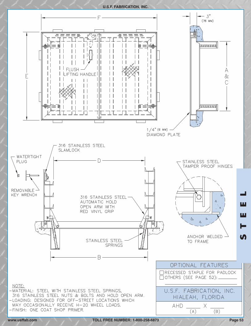
ST
EE
L
U.S.F. FABRICATION, INC.
TOLL FREE NUMBER: 1-800-258-6873 Page 53www.usffab.com

TROUGH FRAME, PEDESTRIAN LOADING, SINGLE DOOR
U.S.F. FABRICATION, INC.
STEELThe trough type floor access door with drainable frame is designed for interior and exterior applications where dirt and water are tobe prevented from falling into the area below.
SPECIFICATIONS: The floor access door shall be Model TPS as manufactured by U.S.F. Fabrication, Inc. with the size beingspecified on the plans. Door leaf shall be 1/4-inch thick steel diamond plate reinforced for a 300 p.s.f. live load. The trough frameshall be fabricated from 1/4-inch thick steel and shall have a continuous anchor flange on all four sides. The frame shall drain waterout through a 1 1/2-inch pipe coupling. The floor access door shall be equipped with a flush steel lifting handle that does notprotrude above the cover, and a 316 stainless steel hold open arm with red vinyl grip that automatically keeps the cover in its upright,open position. The door shall have 316 stainless steel hinges and 316 stainless steel tamper resistant bolts/locknuts. A staple for apadlock shall be supplied for security. The floor access door shall be furnished with one coat of shop primer. Installation shall be inaccordance with the manufacturerʼs attached instructions. The door shall be manufactured and assembled in the United States.Manufacturer shall guarantee the door against defects in materials and workmanship for a period of five years.
OPTIONAL FEATURES
300 P.S.F. LOADING
MODELFRAME OPENING*** CLEAR OPENING** OVERALL SIZE WEIGHT*
TPS 1/4 (6) 24 (610) 24 (610) 24 (610) 24 (610) 32 (813) 32 (813) 180 (82)TPS 1/4 (6) 24 (610) 30 (762) 24 (610) 30 (762) 32 (813) 38 (965) 205 (93)TPS 1/4 (6) 24 (610) 36 (914) 24 (610) 36 (914) 32 (813) 44 (1118) 230 (104)TPS 1/4 (6) 30 (762) 30 (762) 30 (762) 30 (762) 38 (965) 38 (965) 234 (106)TPS 1/4 (6) 30 (762) 36 (914) 30 (762) 36 (914) 38 (965) 44 (1118) 262 (119)TPS 1/4 (6) 30 (762) 48 (1219) 29 (737) 48 (1219) 38 (965) 56 (1422) 326 (148)TPS 1/4 (6) 36 (914) 36 (914) 35 (889) 36 (914) 44 (1118) 44 (1118) 304 (138)TPS 1/4 (6) 36 (914) 48 (1219) 35 (889) 48 (1219) 44 (1118) 56 (1422) 368 (167)TPS 1/4 (6) 42 (1067) 42 (1067) 41 (1041) 42 (1067) 50 (1270) 50 (1270) 375 (170)
in. (mm) A in. (mm) B in. (mm) C in. (mm) F in. (mm)D in. (mm) E in. (mm) Lbs. (KG)COVER THK
� Stainless steel horizontal springs for easy opening, seepage 81
� 316 Stainless steel watertight slamlock and other lockingdevices, see page 78
� Frame skirts for easy casting into a concrete top slab, seepage 78
� Odor reduction gasket, see page 79� Nut rails with stainless steel sliding nuts for attaching
cable holders, bracket & other hardware, see page 85� Fiberglass insulation with metal liner, see page 80� Custom lettering, see page 79
� Stainless steel safety chains with aluminum supportposts, see page 80
� Fall Through Prevention Systems, sees pages 82-83� Side drain coupling (instead of standard bottom drain)� Hot dipped galvanized finish� Mill finish (no shop primer)� All 304 stainless steel material� All 316 stainless steel material� Slip resistant surface bonded to cover plate, see page 80� Reading Lid, see page 76
*Weight shown is of our standard hatch only, and does not include any optional features. **Also referred to as "Actual Opening"which can vary to suit application. ***Also referred to as "Concrete Opening" when door is cast into concrete.
CUSTOM SIZES READILY AVAILABLE
TOLL FREE NUMBER: 1-800-258-6873
ST
EE
L
Page 54 www.usffab.com
We reserve the right to modify specifications and drawings without prior notice.

ST
EE
L
U.S.F. FABRICATION, INC.
TOLL FREE NUMBER: 1-800-258-6873 Page 55www.usffab.com

TROUGH FRAME, PEDESTRIAN LOADING, DOUBLE DOOR
U.S.F. FABRICATION, INC.
STEELThe trough type floor access door with drainable frame is designed for interior and exterior applications where dirt and water are tobe prevented from falling into area below.
SPECIFICATIONS: The floor access door shall be Model TPD as manufactured by U.S.F. Fabrication, Inc. with the size beingspecified on the plans. Door leaves shall be 1/4-inch thick steel diamond plate reinforced for a 300 p.s.f. live load. The trough frameshall be fabricated from 1/4-inch thick steel and shall have a continuous anchor flange on all four sides. The frame shall drain waterout through a 1 1/2-inch pipe coupling. The floor access door shall be equipped with a flush steel lifting handle that does notprotrude above the cover, and 316 stainless steel hold open arms with red vinyl grips that automatically keep the covers in theirupright, open positions. The door shall have 316 stainless steel hinges and 316 stainless steel tamper resistant bolts/locknuts. Astaple for a padlock shall be supplied for security. The floor access door shall be furnished with one coat of shop primer. Installationshall be in accordance with the manufacturerʼs attached instructions. The door shall be manufactured and assembled in the UnitedStates. Manufacturer shall guarantee the door against defects in materials and workmanship for a period of five years
OPTIONAL FEATURES
300 P.S.F. LOADING
MODELFRAME OPENING*** CLEAR OPENING** OVERALL SIZE WEIGHT*
TPD 1/4 (6) 30 (762) 48 (1219) 30 (762) 48 (1219) 38 (965) 56 (1422) 342 (155)TPD 1/4 (6) 30 (762) 54 (1372) 30 (762) 54 (1372) 38 (965) 62 (1575) 371 (168)TPD 1/4 (6) 36 (914) 48 (1219) 36 (914) 48 (1219) 44 (1118) 56 (1422) 384 (174)TPD 1/4 (6) 36 (914) 60 (1524) 36 (914) 60 (1524) 44 (1118) 68 (1727) 448 (203)TPD 1/4 (6) 42 (1067) 48 (1219) 42 (1067) 48 (1219) 50 (1270) 56 (1422) 425 (193)TPD 1/4 (6) 48 (1219) 48 (1219) 48 (1219) 47 (1194) 56 (1422) 56 (1422) 470 (213)TPD 1/4 (6) 48 (1219) 54 (1372) 48 (1219) 53 (1346) 56 (1422) 62 (1575) 508 (230)TPD 1/4 (6) 48 (1219) 72 (1829) 48 (1219) 70 (1778) 56 (1422) 80 (2032) 645 (293)TPD 1/4 (6) 60 (1524) 60 (1524) 60 (1524) 57 (1448) 68 (1727) 68 (1727) 658 (298)
in. (mm) A in. (mm) B in. (mm) C in. (mm) F in. (mm)D in. (mm) E in. (mm) Lbs. (KG)COVER THK
� Stainless steel horizontal springs for easy opening, seepage 81
� 316 Stainless steel watertight slamlock and otherlocking devices, see page 78
� Frame skirts for easy casting into a concrete top slab,see page 78
� Odor reduction gasket, see page 79� Nut rails with stainless steel sliding nuts for attaching
cable holders, bracket & other hardware, see page 85� Fiberglass insulation with metal liner, see page 80� Custom lettering, see page 79
� Stainless steel safety chains, see page 80� Fall Through Prevention Systems, see pages 82-83� Side drain coupling (instead of standard bottom drain)� Hot dipped galvanized finish� Mill finish (no shop primer)� All 304 stainless steel material� All 316 stainless steel material� Slip resistant surface bonded to cover plate, see page 80� Hinge covers on same long side, see page 84� Reading Lid, see page 76
*Weight shown is of our standard hatch only, and does not include any optional features. **Also referred to as "Actual Opening"which can vary to suit application. ***Also referred to as "Concrete Opening" when door is cast into concrete.
CUSTOM SIZES READILY AVAILABLE
TOLL FREE NUMBER: 1-800-258-6873
ST
EE
L
www.usffab.comPage 56
We reserve the right to modify specifications and drawings without prior notice.

ST
EE
L
U.S.F. FABRICATION, INC.
TOLL FREE NUMBER: 1-800-258-6873 Page 57www.usffab.com
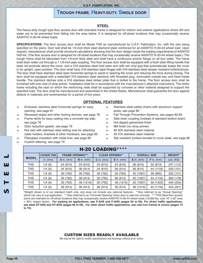
TROUGH FRAME, HEAVY-DUTY, SINGLE DOOR
U.S.F. FABRICATION, INC.
STEELThe heavy-duty trough type floor access door with drainable frame is designed for interior and exterior applications where dirt andwater are to be prevented from falling into the area below. It is designed for off-street locations that may occasionally receiveAASHTO H-20-44 wheel loads.
SPECIFICATIONS: The floor access door shall be Model THS as manufactured by U.S.F. Fabrication, Inc. with the size beingspecified on the plans. Door leaf shall be 1/4-inch thick steel diamond plate reinforced for an AASHTO H-20-44 wheel load. Uponrequest, manufacturer shall provide structural calculations showing that the door design meets the loading requirements of AASHTOH20-44. (The floor access door is designed for off-street locations that may occasionally receive AASHTO H-20-44 wheel loads.) Thetrough frame shall be fabricated from 1/4-inch thick steel and shall have a continuous anchor flange on all four sides. The frameshall drain water out through a 1 1/2-inch pipe coupling. The floor access door shall be equipped with a flush steel lifting handle thatdoes not protrude above the cover, and a 316 stainless steel hold open arm with red vinyl grip that automatically keeps the coverin its upright, open position. The door shall have 316 stainless steel hinges with 316 stainless steel tamper resistant bolts/locknuts.The door shall have stainless steel open horizontal springs to assist in opening the cover and reducing the force during closing. Thedoor shall be equipped with a watertight 316 stainless steel slamlock with threaded plug, removable outside key, and fixed insidehandle. The slamlock latches onto a 316 stainless steel striker plate that is bolted to the frame. The floor access door shall befurnished with one coat of shop primer. Installation shall be in accordance with the manufacturerʼs attached instructions. The entireframe including the seat on which the reinforcing rests shall be supported by concrete or other material designed to support thespecified load. The door shall be manufactured and assembled in the United States. Manufacturer shall guarantee the door againstdefects in materials and workmanship for a period of five years
OPTIONAL FEATURES
H-20 LOADING****
MODELFRAME OPENING*** CLEAR OPENING** OVERALL SIZE WEIGHT*
THS 1/4 (6) 24 (610) 24 (610) 24 (610) 24 (610) 36 (914) 32 (813) 247 (112)THS 1/4 (6) 24 (610) 36 (914) 24 (610) 36 (914) 36 (914) 44 (1118) 333 (151)THS 1/4 (6) 30 (762) 30 (762) 30 (762) 30 (762) 42 (1067) 38 (965) 332 (151)THS 1/4 (6) 30 (762) 36 (914) 30 (762) 36 (914) 42 (1067) 44 (1118) 393 (178)THS 1/4 (6) 30 (762) 48 (1219) 30 (762) 48 (1219) 42 (1067) 56 (1422) 494 (224)THS 1/4 (6) 36 (914) 36 (914) 36 (914) 36 (914) 48 (1219) 44 (1118) 443 (201)
in. (mm) A in. (mm) B in. (mm) C in. (mm) F in. (mm)D in. (mm) E in. (mm) Lbs. (KG)COVER THK
� Enclosed, stainless steel horizontal springs for easyopening, see page 81
� Recessed staple and other locking devices, see page 78� Frame skirts for easy casting into a concrete top slab,
see page 78� Odor reduction gasket, see page 79� Nut rails with stainless steel sliding nuts for attaching
cable holders, brackets & other hardware, see page 85� Fiberglass insulation with metal liner, see page 80� Custom lettering, see page 79
� Stainless steel safety chains with aluminum supportposts, see page 80
� Fall Through Prevention Systems, see pages 82-83� Side drain coupling (instead of standard bottom drain)� Hot dipped galvanized finish� Mill finish (no shop primer)� All 304 stainless steel material� All 316 stainless steel material� Slip resistant surface bonded to cover plate, see page 80
*Weight shown is of our standard hatch only, and does not include any optional features. **Also referred to as "Actual Opening"which can vary to suit application. ***Also referred to as "Concrete Opening" when door is cast into concrete. ****THS Steel floor accessdoors are intended for off-street locations that may occasionally receive AASHTO H-20-44 wheel loads (16,000 lbs. over 10” x 20” area+ 30% impact factor). For parking lot applications, see P-AHS and P-AHD (pages 62 to 65). For direct traffic applications,see steel DT-AHS and DT-AHD (pages 66 to 69). For other direct traffic applications, see cast iron frames & covers (pages 74to 75).
CUSTOM SIZES READILY AVAILABLE
TOLL FREE NUMBER: 1-800-258-6873
ST
EE
L
Page 58 www.usffab.com
We reserve the right to modify specifications and drawings without prior notice.

ST
EE
L
U.S.F. FABRICATION, INC.
TOLL FREE NUMBER: 1-800-258-6873 Page 59www.usffab.com
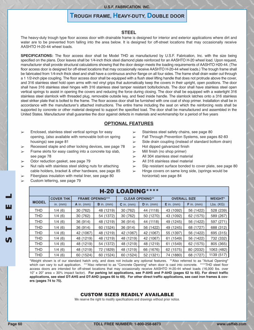
TROUGH FRAME, HEAVY-DUTY, DOUBLE DOOR
U.S.F. FABRICATION, INC.
STEELThe heavy-duty trough type floor access door with drainable frame is designed for interior and exterior applications where dirt andwater are to be prevented from falling into the area below. It is designed for off-street locations that may occasionally receiveAASHTO H-20-44 wheel loads.
SPECIFICATIONS: The floor access door shall be Model THD as manufactured by U.S.F. Fabrication, Inc. with the size beingspecified on the plans. Door leaves shall be 1/4-inch thick steel diamond plate reinforced for an AASHTO H-20 wheel load. Upon request,manufacturer shall provide structural calculations showing that the door design meets the loading requirements of AASHTO H20-44. (Thefloor access door is designed for off-street locations that may occasionally receive AASHTO H-20-44 wheel loads.) The trough frame shallbe fabricated from 1/4-inch thick steel and shall have a continuous anchor flange on all four sides. The frame shall drain water out througha 1 1/2-inch pipe coupling. The floor access door shall be equipped with a flush steel lifting handle that does not protrude above the cover,and 316 stainless steel hold open arms with red vinyl grips that automatically keep the covers in their upright, open positions. The doorshall have 316 stainless steel hinges with 316 stainless steel tamper resistant bolts/locknuts. The door shall have stainless steel openvertical springs to assist in opening the covers and reducing the force during closing. The door shall be equipped with a watertight 316stainless steel slamlock with threaded plug, removable outside key, and fixed inside handle. The slamlock latches onto a 316 stainlesssteel striker plate that is bolted to the frame. The floor access door shall be furnished with one coat of shop primer. Installation shall be inaccordance with the manufacturerʼs attached instructions. The entire frame including the seat on which the reinforcing rests shall besupported by concrete or other material designed to support the specified load. The door shall be manufactured and assembled in theUnited States. Manufacturer shall guarantee the door against defects in materials and workmanship for a period of five years
OPTIONAL FEATURES
H-20 LOADING****
MODELFRAME OPENING*** CLEAR OPENING** OVERALL SIZE WEIGHT*
THD 1/4 (6) 30 (762) 48 (1219) 30 (762) 44 (1118) 43 (1092) 56 (1422) 528 (239)THD 1/4 (6) 30 (762) 54 (1372) 30 (762) 50 (1270) 43 (1092) 62 (1575) 589 (267)THD 1/4 (6) 36 (914) 48 (1219) 36 (914) 44 (1118) 49 (1245) 56 (1422) 597 (271)THD 1/4 (6) 36 (914) 60 (1524) 36 (914) 56 (1422) 49 (1245) 68 (1727) 688 (312)THD 1/4 (6) 42 (1067) 48 (1219) 42 (1067) 42 (1067) 55 (1397) 56 (1422) 695 (315)THD 1/4 (6) 48 (1219) 48 (1219) 48 (1219) 42 (1067) 61 (1549) 56 (1422) 732 (332)THD 1/4 (6) 48 (1219) 54 (1372) 48 (1219) 48 (1219) 61 (1549) 62 (1575) 805 (365)THD 1/4 (6) 48 (1219) 72 (1829) 48 (1219) 66 (1676) 62 (1575) 80 (2032)THD 1/4 (6) 60 (1524) 60 (1524) 60 (1524) 52 (1321) 74 (1880) 68 (1727)
in. (mm) A in. (mm) B in. (mm) C in. (mm) F in. (mm)D in. (mm) E in. (mm) Lbs. (KG)COVER THK
� Enclosed, stainless steel vertical springs for easyopening, (also available with removable bolt-on springhousings) see page 81
� Recessed staple and other locking devices, see page 78� Frame skirts for easy casting into a concrete top slab,
see page 78� Odor reduction gasket, see page 79� Nut rails with stainless steel sliding nuts for attaching
cable holders, bracket & other hardware, see page 85� Fiberglass insulation with metal liner, see page 80� Custom lettering, see page 79
� Stainless steel safety chains, see page 80� Fall Through Prevention Systems, see pages 82-83� Side drain coupling (instead of standard bottom drain)� Hot dipped galvanized finish� Mill finish (no shop primer)� All 304 stainless steel material� All 316 stainless steel material� Slip resistant surface bonded to cover plate, see page 80� Hinge covers on same long side, (springs would be
horizontal) see page 84
*Weight shown is of our standard hatch only, and does not include any optional features. **Also referred to as "Actual Opening"which can vary to suit application. ***Also referred to as "Concrete Opening" when door is cast into concrete. ****THD steel flooraccess doors are intended for off-street locations that may occasionally receive AASHTO H-20-44 wheel loads (16,000 lbs. over10” x 20” area + 30% impact factor). For parking lot applications, see P-AHS and P-AHD (pages 62 to 65). For direct trafficapplications, see steel DT-AHS and DT-AHD (pages 66 to 69). For other direct traffic applications, see cast iron frames & cov-ers (pages 74 to 75).
1139 (517)1063 (482)
CUSTOM SIZES READILY AVAILABLE
TOLL FREE NUMBER: 1-800-258-6873
ST
EE
L
Page 60 www.usffab.com
We reserve the right to modify specifications and drawings without prior notice.

ST
EE
L
U.S.F. FABRICATION, INC.
TOLL FREE NUMBER: 1-800-258-6873www.usffab.com Page 61

PARKING LOT TRAFFIC
ANGLE FRAME, HEAVY-DUTY, SINGLE DOOR
U.S.F. FABRICATION, INC.
STEELThe heavy-duty angle type floor access door is designed for interior and exterior applications where watertightness is not required.It is designed for AASHTO H-20-44 wheel loads in parking lots and alleyways where traffic speeds will not exceed 15 mph.
SPECIFICATIONS: The floor access door shall be Model P-AHS as manufactured by U.S.F. Fabrication, Inc., with the size beingspecified on the plans. Door leaf shall be 1/4-inch thick steel diamond plate reinforced for an AASHTO H-20-44 wheel load. Uponrequest, manufacturer shall provide structural calculations showing that the door design meets the loading requirements ofAASHTO H-20-44. The frame shall be 1/4-inch thick steel angle with anchors welded to the frame for casting into concrete. In theclosed position, the cover shall be bolted to the frame with 316 stainless steel bolts. (The bolts must be securely fastenedwhenever the cover is closed to insure safe and proper performance of the door.) The floor access door shall be equipped with aflush steel lifting handle that does not protrude above the cover, and a 316 stainless steel hold open arm with red vinyl grip thatautomatically locks the cover in its upright, open position. A steel skirt shall be welded to the frame to provide a combined heightequal to the depth of the concrete slab. The door shall have tamper resistant hinges with recessed stainless steel pins and lugs.The door shall have open, stainless steel, horizontal, compression springs to assist in opening the cover and reducing the forceduring closing. The floor access door shall have a hot-dipped galvanized finish. Installation shall be in accordance with themanufacturerʼs attached instructions. The entire frame, including the seat on which the reinforcing rests, shall be supported byconcrete or other material designed to support the specified load. The door shall be manufactured and assembled in the UnitedStates. Manufacturer shall guarantee the door against defects in materials and workmanship for a period of five years.
OPTIONAL FEATURES
H-20 LOADING****
MODELFRAME OPENING*** CLEAR OPENING** OVERALL SIZE WEIGHT*
P-AHS 1/4 (6) 24 (610) 24 (610) 23 (584) 23 (584) 31 (787) 30 (762) 227 (103)P-AHS 1/4 (6) 24 (610) 36 (914) 23 (584) 35 (889) 31 (787) 42 (1067) 314 (142)P-AHS 1/4 (6)) 30 (762) 30 (762) 28 (711) 29 (737) 37 (940) 36 (914) 333 (151)P-AHS 1/4 (6)) 30 (762) 36 (914) 28 (711) 35 (889) 37 (940) 42 (1067) 382 (173)P-AHS 1/4 (6) 30 (762) 48 (1219) 28 (711) 47 (1194) 37 (940) 54 (1372) 488 (221)P-AHS 1/4 (6) 36 (914) 36 (914) 34 (864) 35 (889) 43 (1092) 42 (1067) 438 (199)
in. (mm) A in. (mm) B in. (mm) C in. (mm) F in. (mm)D in. (mm) E in. (mm) Lbs. (KG)MAT’L THK
*Weight shown is of our standard hatch only, and does not include any optional features. **Also referred to as “Actual Opening” whichcan vary to suit application. ***Also referred to as “Concrete Opening” when door is cast into concrete. ****P-AHS steel floor accessdoors are intended for parking lot traffic locations where the posted speed does not exceed 15 mph and will receive AASHTO H-20-44wheel loads (16,000 lbs. over 10” x 20” area + 30% impact factor). For direct traffic applications, see steel DT-AHS and DT-AHD(pages 66 to 69). For other direct traffic applications, see cast iron frames & covers (pages 74 to 75).
CUSTOM SIZES READILY AVAILABLE
TOLL FREE NUMBER: 1-800-258-6873
ST
EE
L
Page 62 www.usffab.com
� Enclosed stainless steel springs, see page 81� Oversized recessed padlock box, see page 78� Skirts for concrete slabs deeper than 12 inches� Nut rails with stainless steel sliding nuts for attaching
hardware, see page 85� Custom lettering, see page 79
� Stainless steel safety chains and posts, see page 80� Fall Through Prevention Systems, see pages 82-83� All 304 stainless steel material� All 316 stainless steel material� Slip resistant surface bonded to cover plate, see
page 80
We reserve the right to modify specifications and drawings without prior notice.

Page 63www.usffab.com
U.S.F. FABRICATION, INC.
TOLL FREE NUMBER: 1-800-258-6873
ST
EE
L
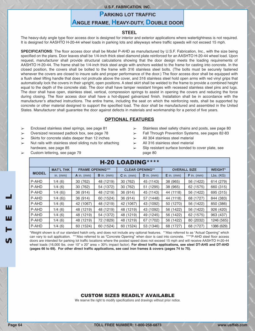
PARKING LOT TRAFFIC
ANGLE FRAME, HEAVY-DUTY, DOUBLE DOOR
U.S.F. FABRICATION, INC.
STEELThe heavy-duty angle type floor access door is designed for interior and exterior applications where watertightness is not required.It is designed for AASHTO H-20-44 wheel loads in parking lots and alleyways where traffic speeds will not exceed 15 mph.
SPECIFICATIONS: The floor access door shall be Model P-AHD as manufactured by U.S.F. Fabrication, Inc., with the size beingspecified on the plans. Door leaves shall be 1/4-inch thick steel diamond plate reinforced for an AASHTO H-20-44 wheel load. Uponrequest, manufacturer shall provide structural calculations showing that the door design meets the loading requirements ofAASHTO H-20-44. The frame shall be 1/4-inch thick steel angle with anchors welded to the frame for casting into concrete. In theclosed position, the covers shall be bolted to the frame with 316 stainless steel bolts. (The bolts must be securely fastenedwhenever the covers are closed to insure safe and proper performance of the door.) The floor access door shall be equipped witha flush steel lifting handle that does not protrude above the cover, and 316 stainless steel hold open arms with red vinyl grips thatautomatically lock the covers in their upright, open positions. A steel skirt shall be welded to the frame to provide a combined heightequal to the depth of the concrete slab. The door shall have tamper resistant hinges with recessed stainless steel pins and lugs.The door shall have open, stainless steel, vertical, compression springs to assist in opening the covers and reducing the forceduring closing. The floor access door shall have a hot-dipped galvanized finish. Installation shall be in accordance with themanufacturerʼs attached instructions. The entire frame, including the seat on which the reinforcing rests, shall be supported byconcrete or other material designed to support the specified load. The door shall be manufactured and assembled in the UnitedStates. Manufacturer shall guarantee the door against defects in materials and workmanship for a period of five years.
OPTIONAL FEATURES
H-20 LOADING****
MODELFRAME OPENING*** CLEAR OPENING** OVERALL SIZE WEIGHT*
P-AHD 1/4 (6) 30 (762) 48 (1219) 30 (762) 45 (1143) 38 (965) 56 (1422) 614 (279)P-AHD 1/4 (6) 30 (762) 54 (1372) 30 (762) 51 (1295) 38 (965) 62 (1575) 660 (315)P-AHD 1/4 (6)) 36 (914) 48 (1219) 36 (914) 45 (1143) 44 (1118) 56 (1422) 695 (315)
P-AHD 1/4 (6) 48 (1219) 48 (1219) 48 (1219) 43 (1092) 56 (1422) 56 (1422) 926 (420)P-AHD 1/4 (6) 48 (1219) 54 (1372) 48 (1219) 49 (1245) 56 (1422) 62 (1575) 963 (437)P-AHD 1/4 (6) 48 (1219) 72 (1829) 48 (1219) 67 (1702) 56 (1422) 80 (2032) 1246 (565)P-AHD 1/4 (6) 60 (1524) 60 (1524) 60 (1524) 53 (1346) 68 (1727) 68 (1727) 1386 (629)
in. (mm) A in. (mm) B in. (mm) C in. (mm) F in. (mm)D in. (mm) E in. (mm) Lbs. (KG)MAT’L THK
*Weight shown is of our standard hatch only, and does not include any optional features. **Also referred to as “Actual Opening” whichcan vary to suit application. ***Also referred to as “Concrete Opening” when door is cast into concrete. ****P-AHD steel floor accessdoors are intended for parking lot traffic locations where the posted speed does not exceed 15 mph and will receive AASHTO H-20-44wheel loads (16,000 lbs. over 10” x 20” area + 30% impact factor). For direct traffic applications, see steel DT-AHS and DT-AHD(pages 66 to 69). For other direct traffic applications, see cast iron frames & covers (pages 74 to 75).
CUSTOM SIZES READILY AVAILABLE
TOLL FREE NUMBER: 1-800-258-6873
ST
EE
L
Page 64 www.usffab.com
� Enclosed stainless steel springs, see page 81� Oversized recessed padlock box, see page 78� Skirts for concrete slabs deeper than 12 inches� Nut rails with stainless steel sliding nuts for attaching
hardware, see page 85� Custom lettering, see page 79
� Stainless steel safety chains and posts, see page 80� Fall Through Prevention Systems, see pages 82-83� All 304 stainless steel material� All 316 stainless steel material� Slip resistant surface bonded to cover plate, see
page 80
P-AHD 1/4 (6)) 36 (914) 60 (1524) 36 (914) 57 (1448) 44 (1118) 68 (1727) 844 (383)P-AHD 1/4 (6) 42 (1067) 48 (1219) 42 (1067) 43 (1092) 50 (1270) 56 (1422) 850 (386)
We reserve the right to modify specifications and drawings without prior notice.
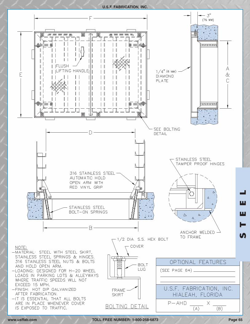
Page 65www.usffab.com TOLL FREE NUMBER: 1-800-258-6873
ST
EE
L
U.S.F. FABRICATION, INC.

DIRECT TRAFFIC
ANGLE FRAME, HEAVY-DUTY, SINGLE DOOR
U.S.F. FABRICATION, INC.
STEELThe heavy-duty angle type floor access door is designed for interior and exterior applications where watertightness is not required. Itis designed to receive AASHTO H20-44 wheel loads on two-lane streets with opposing traffic where the posted speed limit does notexceed 35 miles per hour. Areas where these doors cannot be used include—but, are not limited to—roadways inside or leading into:seaport facilities, military bases, airports, landfills, freight terminals, bus terminals and any other area where there is continuouscommercial vehicle traffic.
SPECIFICATIONS: The floor access door shall be Model DT-AHS as manufactured by U.S.F. Fabrication, Inc. with the size beingspecified on the plans. Cover shall be 1/2-inch thick steel diamond plate reinforced for an AASHTO H20-44 wheel load. Uponrequest, manufacturer shall provide structural calculations showing that the door design meets the loading requirements ofAASHTO H20-44. The frame shall be 1/2-inch thick steel angle with anchors welded to frame for casting into concrete. In the closedposition the cover shall be bolted to the frame with 316 stainless steel allen-head bolts to allow for H20-44 direct traffic loading—an allen-head socket with torque wrench will be provided with the door. The allen-head bolts must be tightened to 25 footpounds of torque and securely fastened using Loctite 242 whenever the cover is closed to insure safe and properperformance of the door. For security the cover shall have a recessed staple for a padlock. The floor access door shall beequipped with a flush steel lifting handle that does not protrude above the cover, and hold open arms that automatically keep thecover in its upright, open position. A steel skirt shall be welded to the frame to provide a combined height equal to the depth of theconcrete slab. The door shall have tamper resistant hinges with recessed stainless steel pins and lugs. The door shall have open,stainless steel, horizontal springs to assist in opening the door and reducing the force during closing. The floor access door shall havea hot-dipped galvanized finish. Installation shall be in accordance with the manufacturerʼs attached instructions. The entire frame,including the seat on which the reinforcing rests, shall be supported by concrete or other material designed to support the specifiedload. The door shall be manufactured and assembled in the United States. Manufacturer shall guarantee the door against defects inmaterials and workmanship for a period of five years.
OPTIONAL FEATURES
H-20 LOADING****
MODELFRAME OPENING*** CLEAR OPENING** OVERALL SIZE WEIGHT*
DT-AHS 1/2 (13) 24 (610) 24 (610) 23 (584) 24 (610) 34 (864) 34 (864) 661 (300)DT-AHS 1/2 (13) 24 (610) 36 (914) 23 (584) 36 (914) 34 (864) 46 (1168) 831 (377)DT-AHS 1/2 (13) 30 (762) 30 (762) 29 (737) 30 (762) 40 (1016) 40 (1016) 871 (395)DT-AHS 1/2 (13) 30 (762) 36 (914) 29 (737) 46 (1168) 40 (1016) 46 (1168) 964 (437)DT-AHS 1/2 (13) 30 (762) 48 (1219) 29 (737) 48 (1219) 40 (1016) 58 (1473) 1174 (533)DT-AHS 1/2 (13) 36 (914) 36 (914) 35 (889) 36 (914) 46 (1168) 46 (1168) 1073 (487)DT-AHS 1/2 (13) 42 (1067) 42 (1067) 40 (1016) 42 (1067) 52 (1321) 52 (1321) 1348 (611)
in. (mm) A in. (mm) B in. (mm) C in. (mm) F in. (mm)D in. (mm) E in. (mm) Lbs. (KG)COVER THK
� Skirts for concrete slabs deeper than 12 inches� Nut rails with stainless steel sliding nuts for attaching
cable holders, brackets & other hardware, see page 85� Custom lettering, see page 79
� Stainless steel safety chains with aluminum supportposts, see page 80
� Fall Through Prevention Systems, see pages 82-83
*Weight shown is of our standard hatch only, and does not include any optional features. **Also referred to as “Actual Opening” whichcan vary to suit application. ***Also referred to as “Concrete Opening” when door is cast into concrete. ****DT-AHS steel floor accessdoors are designed for AASHTO H20-44 wheel loads (16,000 lbs. over 10” x 20” area + 30% impact factor) in locations and trafficconditions as above described. For other direct traffic applications, see cast iron frames & covers (pages 74 to 75).
CUSTOM SIZES READILY AVAILABLE
TOLL FREE NUMBER: 1-800-258-6873
ST
EE
L
We reserve the right to modify specifications and drawings without prior notice.
Page 66 www.usffab.com
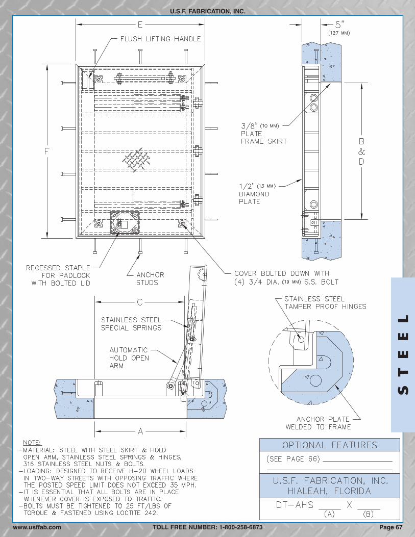
ST
EE
L
U.S.F. FABRICATION, INC.
TOLL FREE NUMBER: 1-800-258-6873www.usffab.com Page 67
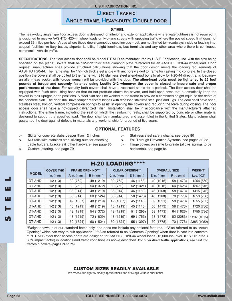
U.S.F. FABRICATION, INC.
STEELThe heavy-duty angle type floor access door is designed for interior and exterior applications where watertightness is not required. Itis designed to receive AASHTO H20-44 wheel loads on two-lane streets with opposing traffic where the posted speed limit does notexceed 35 miles per hour. Areas where these doors cannot be used include—but, are not limited to—roadways inside or leading into:seaport facilities, military bases, airports, landfills, freight terminals, bus terminals and any other area where there is continuouscommercial vehicle traffic.
SPECIFICATIONS: The floor access door shall be Model DT-AHD as manufactured by U.S.F. Fabrication, Inc. with the size beingspecified on the plans. Covers shall be 1/2-inch thick steel diamond plate reinforced for an AASHTO H20-44 wheel load. Uponrequest, manufacturer shall provide structural calculations showing that the door design meets the loading requirements ofAASHTO H20-44. The frame shall be 1/2-inch thick steel angle with anchors welded to frame for casting into concrete. In the closedposition the covers shall be bolted to the frame with 316 stainless steel allen-head bolts to allow for H20-44 direct traffic loading—an allen-head socket with torque wrench will be provided with the door. The allen-head bolts must be tightened to 25 footpounds of torque and securely fastened using Loctite 242 whenever the cover is closed to insure safe and properperformance of the door. For security both covers shall have a recessed staple for a padlock. The floor access door shall beequipped with flush steel lifting handles that do not protrude above the covers, and hold open arms that automatically keep thecovers in their upright, open positions. A steel skirt shall be welded to the frame to provide a combined height equal to the depth ofthe concrete slab. The door shall have tamper resistant hinges with recessed stainless steel pins and lugs. The door shall have open,stainless steel, bolt-on, vertical compression springs to assist in opening the covers and reducing the force during closing. The flooraccess door shall have a hot-dipped galvanized finish. Installation shall be in accordance with the manufacturerʼs attachedinstructions. The entire frame, including the seat on which the reinforcing rests, shall be supported by concrete or other materialdesigned to support the specified load. The door shall be manufactured and assembled in the United States. Manufacturer shallguarantee the door against defects in materials and workmanship for a period of five years.
OPTIONAL FEATURES
H-20 LOADING****
MODELFRAME OPENING*** CLEAR OPENING** OVERALL SIZE WEIGHT*
DT-AHD 1/2 (13) 30 (762) 48 (1219) 30 (762) 46 (1168) 40 (1016) 58 (1473) 1254 (569)DT-AHD 1/2 (13) 30 (762) 54 (1372) 30 (762) 52 (1321) 40 (1016) 64 (1626) 1357 (616)DT-AHD 1/2 (13) 36 (914) 48 (1219) 36 (914) 46 (1168) 46 (1168) 58 (1473) 1415 (642)DT-AHD 1/2 (13) 36 (914) 60 (1524) 36 (914) 58 (1473) 46 (1168) 70 (1778) 1653 (750)DT-AHD 1/2 (13) 42 (1067) 48 (1219) 42 (1067) 45 (1143) 52 (1321) 58 (1473) 1555 (705)DT-AHD 1/2 (13) 48 (1219) 48 (1219) 48 (1219) 45 (1143) 58 (1473) 58 (1473) 1720 (780)DT-AHD 1/2 (13) 48 (1219) 54 (1372) 48 (1219) 51 (1295) 58 (1473) 64 (1626) 1755 (796)DT-AHD 1/2 (13) 48 (1219) 72 (1829) 48 (1219) 69 (1753) 58 (1473) 82 (2083)DT-AHD 1/2 (13) 60 (1524) 60 (1524) 60 (1524) 55 (1397) 70 (1778) 70 (1778)
in. (mm) A in. (mm) B in. (mm) C in. (mm) F in. (mm)D in. (mm) E in. (mm) Lbs. (KG)COVER THK
� Skirts for concrete slabs deeper than 12 inches� Nut rails with stainless steel sliding nuts for attaching
cable holders, brackets & other hardware, see page 85� Custom lettering, see page 79
� Stainless steel safety chains, see page 80� Fall Through Prevention Systems, see pages 82-83� Hinge covers on same long side (allows springs to be
horizontal), see page 84
*Weight shown is of our standard hatch only, and does not include any optional features. **Also referred to as “ActualOpening” which can vary to suit application. ***Also referred to as “Concrete Opening” when door is cast into concrete.****DT-AHS steel floor access doors are designed for AASHTO H20-44 wheel loads (16,000 lbs. over 10” x 20” area +30% impact factor) in locations and traffic conditions as above described. For other direct traffic applications, see cast ironframes & covers (pages 74 to 75).
CUSTOM SIZES READILY AVAILABLE
TOLL FREE NUMBER: 1-800-258-6873
ST
EE
LDIRECT TRAFFIC
ANGLE FRAME, HEAVY-DUTY, DOUBLE DOOR
We reserve the right to modify specifications and drawings without prior notice.
www.usffab.comPage 68
2237 (1015)2385 (1082)
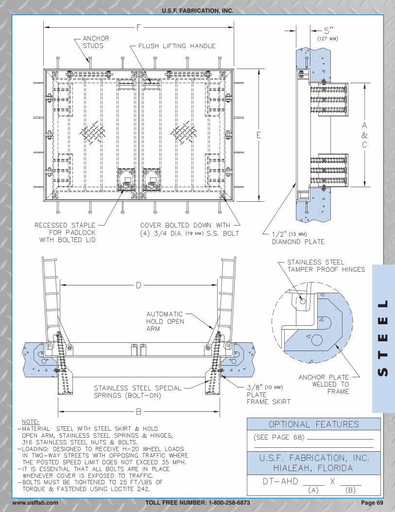
ST
EE
L
U.S.F. FABRICATION, INC.
TOLL FREE NUMBER: 1-800-258-6873www.usffab.com Page 69

AIRCRAFT LOAD HATCH
U.S.F. FABRICATION, INC.
STEELThe aircraft load floor access door is designed for areas that receive loads up to 280 p.s.i. over the entire surface of the cover andwhere watertightness is not required. It is designed for taxi ways and airsides at airports (not runways), marine ports and other areasof extremely heavy and severe loading conditions.
SPECIFICATIONS: The floor access door shall be Model ALH as manufactured by U.S.F. Fabrication, Inc. with the size beingspecified on the plans. Door leaf (leaves) shall be 1/2-inch thick ASTM A36 structural steel diamond plate reinforced with ASTMA572 or A588 structural steel. Hatches with reinforcing rib spans of up to 24 inches shall be designed to carry a maximum load of280 p.s.i. uniformly distributed over the entire cover. For hatches with rib spans over 24 inches, the load capacity decreases linearlyby 25 p.s.i. per foot. The frame shall be 3/8-inch thick material with 1/4" x 2" anchor straps welded to the frame for casting intoconcrete. The floor access door shall be equipped with a flush steel lifting handle(s) that does (do) not protrude above the cover,and steel automatic hold open arm(s) and door stop(s) to automatically keep the cover(s) in the upright, open position. The doorshall have heavy-duty tamper resistant hinges with recessed stainless steel pins and lugs. The corners of the cover (s) shall bebolted to the frame with 3/4-inch diameter stainless steel bolts for security as well as to prevent the cover(s) from rattling. The doorshall be equipped with stainless steel springs to assist in the opening of the door and reduce the force during closing. The flooraccess door shall have a hot dip galvanized finish. Installation shall be in accordance with the manufacturerʼs attached instructions.The entire frame including the seat on which the reinforcing rests shall be supported by concrete or other material designed tosupport the specified load. The door shall be manufactured and assembled in the United States. Manufacturer shall guarantee thedoor against defects in materials and workmanship for a period of five years.
OPTIONAL FEATURES
AIRCRAFT LOADING - 280 P.S.I.****
MODELFRAME OPENING*** CLEAR OPENING** OVERALL SIZE WEIGHT*HEIGHT
ALH 24 (610) 24 (610) 21 (533) 24 (610) 30 (762) 30 (762) 7 (178) 685 (311)ALH 24 (610) 36 (914) 22 (559) 36 (914) 30 (762) 42 (1067) 7 (178) 900 (408)ALH 30 (762) 30 (762) 28 (711) 30 (762) 36 (914) 36 (914) 7 (178) 930 (422)ALH 30 (762) 36 (914) 28 (711) 36 (914) 36 (914) 42 (1067) 8 (203)ALH 30 (762) 48 (1219) 28 (711) 48 (1219) 36 (914) 54 (1372) 8 (203)ALH 36 (914) 36 (914) 34 (864) 36 (914) 42 (1067) 42 (1067) 8 (203)ALH 48 (1219) 48 (1219) 48 (1219) 42 (1067) 58 (1473) 58 (1473) 8 (203)
A in. (mm) B in. (mm) C in. (mm) D in. (mm) G in. (mm)E in. (mm) F in. (mm) Lbs. (KG)
� Frame skirts for easy casting into a concrete top slab,see page 78
� Custom lettering, see page 79
� Fall Through Prevention Systems, see pages 82-83� Slip resistant surface bonded to cover plate, see page 80
*Weight shown is of our standard hatch only, and does not include any optional features. **Also referred to as "Actual Opening"which can vary to suit application. ***Also referred to as "Concrete Opening" when door is cast into concrete. ****Load criteria arebased on a linear reduction from 280 p.s.i. for a 2 foot span to 80 p.s.i. for a 10 foot span (Ref. FAA AC 150/5320-6c).
The ALH 48 x 48 is manufactured as a double door hatch with vertical springs.
2200 (998)1165 (528)1245 (565)1051 (477)
CUSTOM SIZES & LOADING READILY AVAILABLE
TOLL FREE NUMBER: 1-800-258-6873
ST
EE
L
�
�
www.usffab.comPage 70
We reserve the right to modify specifications and drawings without prior notice.

ST
EE
L
U.S.F. FABRICATION, INC.
TOLL FREE NUMBER: 1-800-258-6873 Page 71www.usffab.com
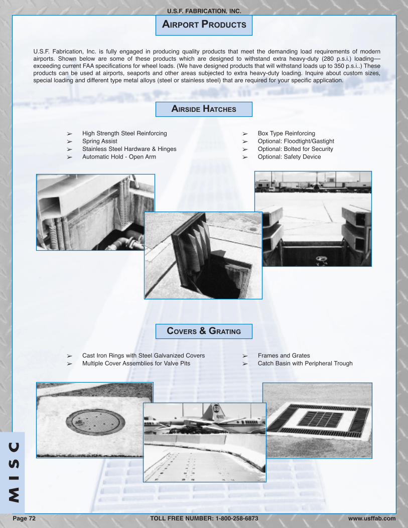
AIRPORT PRODUCTS
U.S.F. FABRICATION, INC.
U.S.F. Fabrication, Inc. is fully engaged in producing quality products that meet the demanding load requirements of modernairports. Shown below are some of these products which are designed to withstand extra heavy-duty (280 p.s.i.) loading––exceeding current FAA specifications for wheel loads. (We have designed products that will withstand loads up to 350 p.s.i..) Theseproducts can be used at airports, seaports and other areas subjected to extra heavy-duty loading. Inquire about custom sizes,special loading and different type metal alloys (steel or stainless steel) that are required for your specific application.
� High Strength Steel Reinforcing� Spring Assist� Stainless Steel Hardware & Hinges� Automatic Hold - Open Arm
� Box Type Reinforcing� Optional: Floodtight/Gastight� Optional: Bolted for Security� Optional: Safety Device
� Cast Iron Rings with Steel Galvanized Covers� Multiple Cover Assemblies for Valve Pits
� Frames and Grates� Catch Basin with Peripheral Trough
COVERS & GRATING
AIRSIDE HATCHES
TOLL FREE NUMBER: 1-800-258-6873
MI
SC
Page 72 www.usffab.com
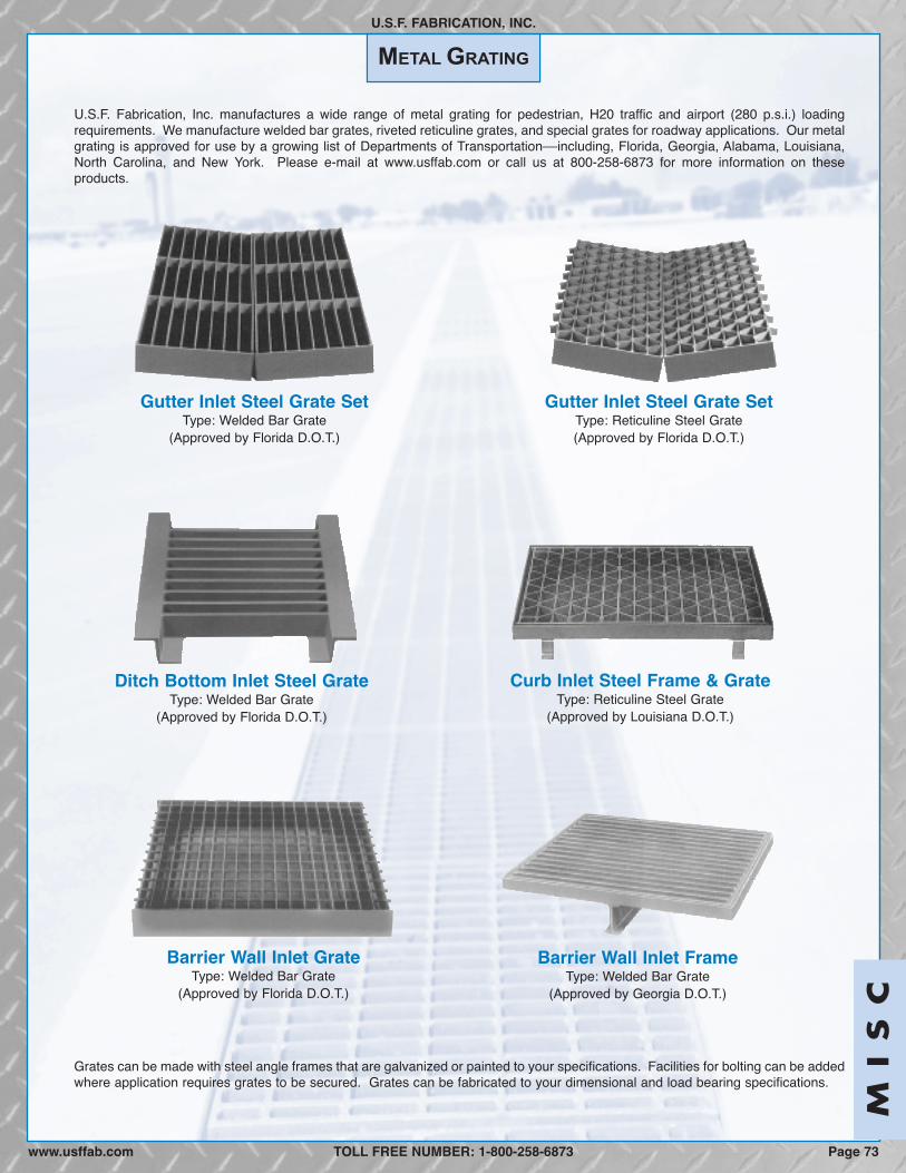
MI
SC
U.S.F. Fabrication, Inc. manufactures a wide range of metal grating for pedestrian, H20 traffic and airport (280 p.s.i.) loadingrequirements. We manufacture welded bar grates, riveted reticuline grates, and special grates for roadway applications. Our metalgrating is approved for use by a growing list of Departments of Transportation––including, Florida, Georgia, Alabama, Louisiana,North Carolina, and New York. Please e-mail at www.usffab.com or call us at 800-258-6873 for more information on theseproducts.
Gutter Inlet Steel Grate SetType: Reticuline Steel Grate(Approved by Florida D.O.T.)
METAL GRATING
Grates can be made with steel angle frames that are galvanized or painted to your specifications. Facilities for bolting can be addedwhere application requires grates to be secured. Grates can be fabricated to your dimensional and load bearing specifications.
Curb Inlet Steel Frame & GrateType: Reticuline Steel Grate
(Approved by Louisiana D.O.T.)
Barrier Wall Inlet GrateType: Welded Bar Grate
(Approved by Florida D.O.T.)
Barrier Wall Inlet FrameType: Welded Bar Grate
(Approved by Georgia D.O.T.)
U.S.F. FABRICATION, INC.
TOLL FREE NUMBER: 1-800-258-6873
Gutter Inlet Steel Grate SetType: Welded Bar Grate
(Approved by Florida D.O.T.)
Ditch Bottom Inlet Steel GrateType: Welded Bar Grate
(Approved by Florida D.O.T.)
Page 73www.usffab.com
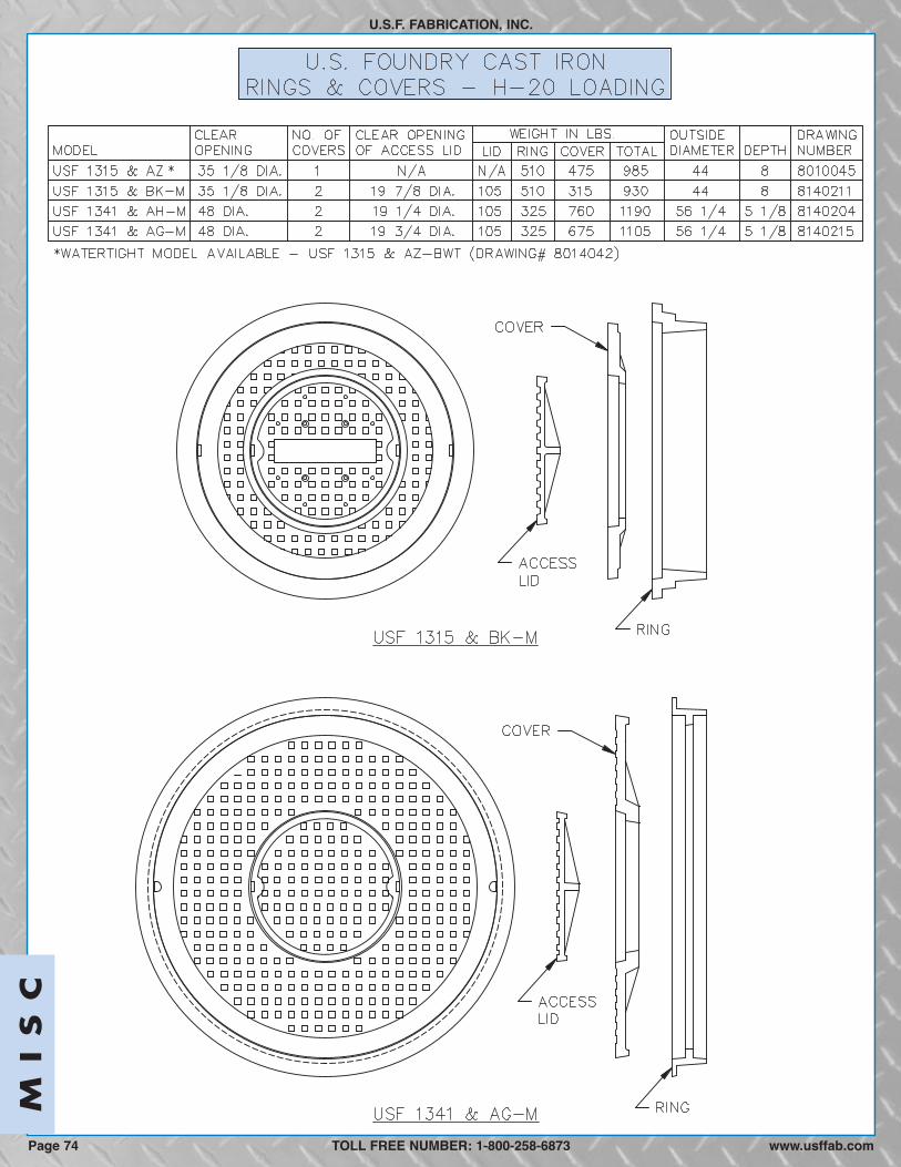
U.S.F. FABRICATION, INC.
TOLL FREE NUMBER: 1-800-258-6873
MI
SC
Page 74 www.usffab.com
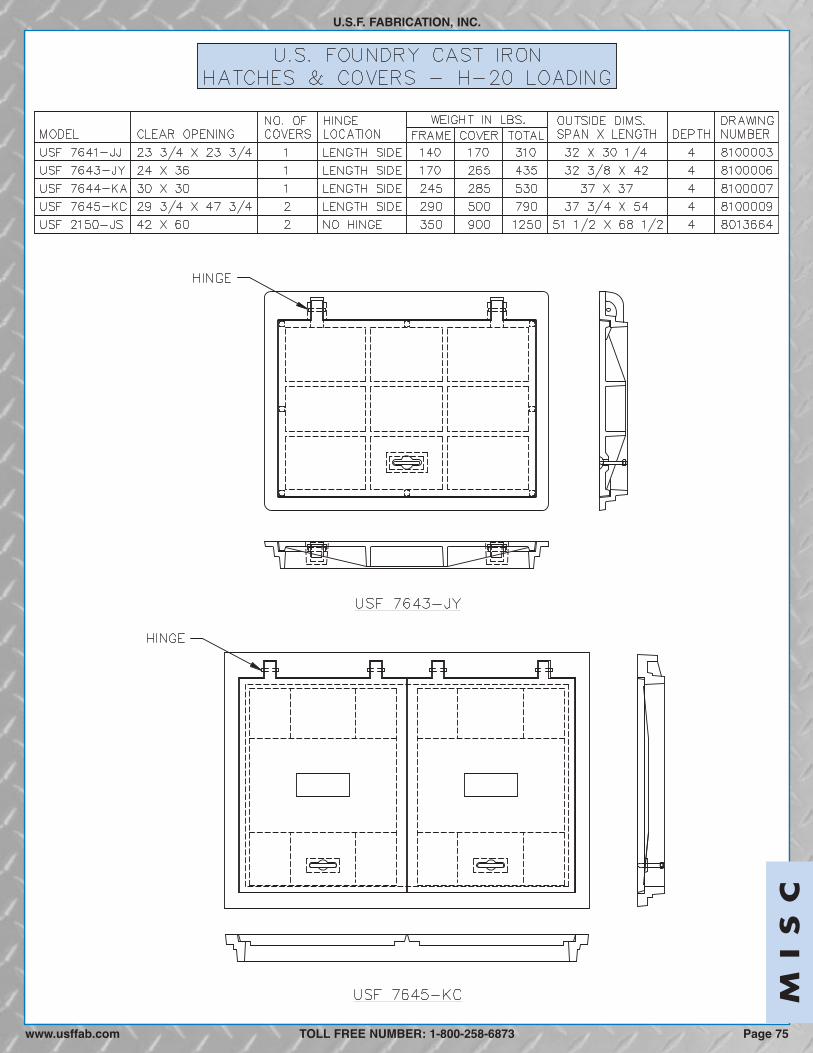
MI
SC
U.S.F. FABRICATION, INC.
TOLL FREE NUMBER: 1-800-258-6873 Page 75www.usffab.com
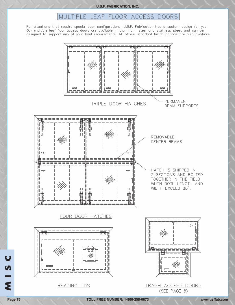
U.S.F. FABRICATION, INC.
TOLL FREE NUMBER: 1-800-258-6873
MI
SC
Page 76 www.usffab.com

MI
SC
U.S.F. FABRICATION, INC.
TOLL FREE NUMBER: 1-800-258-6873 Page 77www.usffab.com
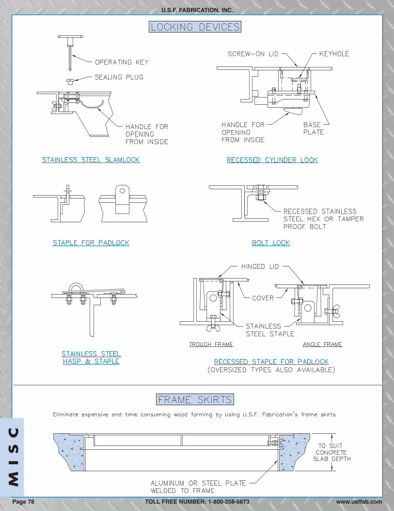
U.S.F. FABRICATION, INC.
TOLL FREE NUMBER: 1-800-258-6873
MI
SC
Page 78 www.usffab.com
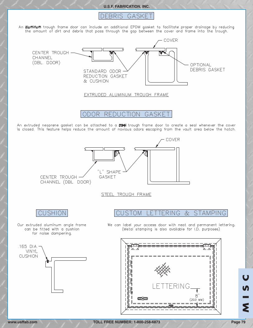
MI
SC
U.S.F. FABRICATION, INC.
TOLL FREE NUMBER: 1-800-258-6873www.usffab.com Page 79
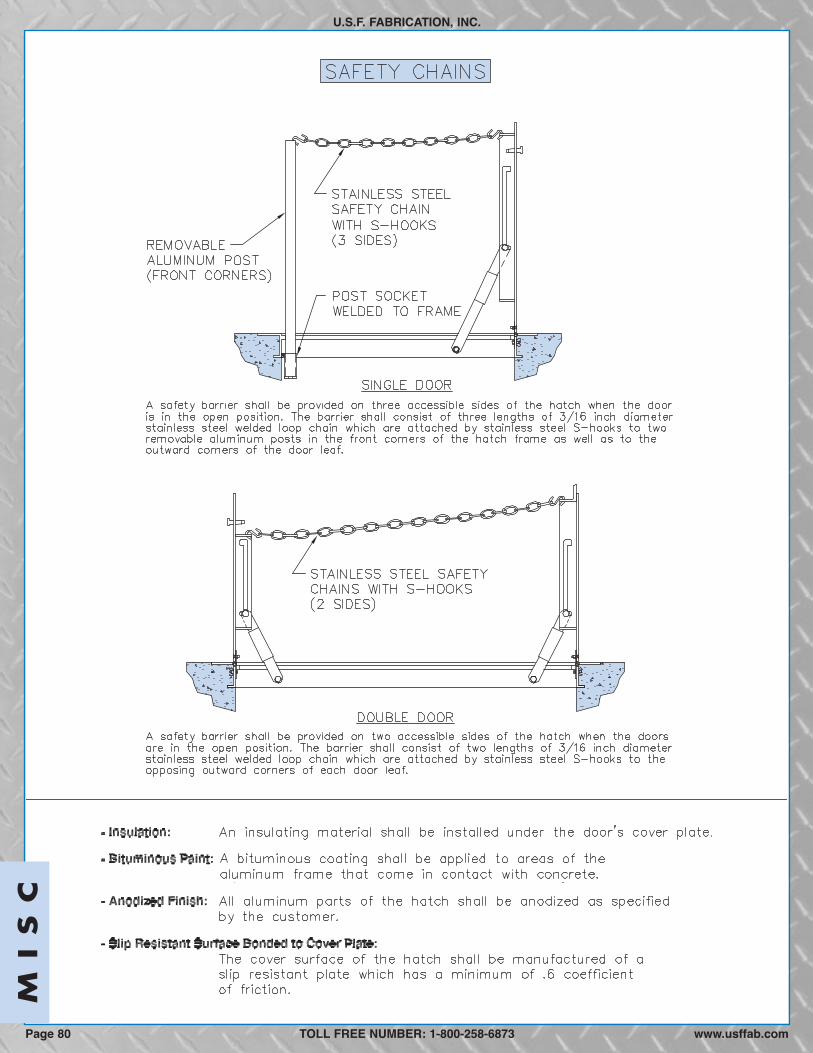
U.S.F. FABRICATION, INC.
TOLL FREE NUMBER: 1-800-258-6873
MI
SC
Page 80 www.usffab.com
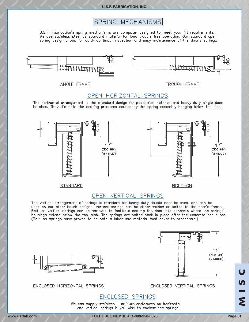
MI
SC
U.S.F. FABRICATION, INC.
TOLL FREE NUMBER: 1-800-258-6873www.usffab.com Page 81

TOLL FREE NUMBER: 1-800-258-6873
MI
SC
Page 82 www.usffab.com
FALL THROUGH PREVENTION SYSTEMS
HATCH SAFETY NET
DESCRIPTION: The Hatch Safety Net is made of super strong polyesternetting which attaches to aluminum angle anchors on the frame by stainlesssteel hardware that resist corrosion. The Hatch Safety Net is the mosteconomical fall-through prevention alternative.
FEATURES:The lightweight design of the Hatch Safety Net makes it easilyretractable in floor and roof openings. When closed, it provides fall-throughprevention, the greatest visibility for inspections, and the most accessibilityfor limited maintenance (e.g., float adjustments) in the space below. Whennecessary, the net can be easily unhooked to permit full access into theconfined space. (Complies with OSHA standard 1926.502, Drop Test.)
RETROFIT: The Hatch Safety Net can be economically and easily retrofittedinto existing openings. It can be manufactured to fit the custom dimensions ofalmost any type floor access hatch, roof scuttle, automatic fire vent or skylightwith minimal reduction of their clear opening. (See worksheet on page 92.)
U.S.F. FABRICATION, INC.
HATCH SAFETY GRATEDESCRIPTION: The Hatch Safety Grate smoothly rotates to its open, upright position andlocks in place by a hold-open rod. The aluminum grate has an OSHA safety orange finish.Hardware components are made of stainless steel to resist corrosion.
FEATURES: When in its closed position, the Hatch Safety Grate provides fall-throughprevention while allowing limited accessibility into the vault for maintenance purposes andvisibility for inspections (nominal 4 x 6 inch grate openings). When opened, it acts as anadditional barrier to the access door opening. Finally, since the hatch cover cannot be shutwithout first closing the Hatch Safety Grate, this fall-through system is always in its closedposition when the next operator opens the hatchʼs cover. USF Fabrication safety gratesoperate independently of the coverʼs reinforcing so that the cover continues to meet itsspecified load and deflection requirements, even if the grate is damaged or removed. (Grate isdesigned for 300 p.s.f. loading.)
RETROFIT: The Hatch Safety Grate can be retrofitted onto the vault walls under an accessdoor that is already in service. While it can be made to fit the custom dimensions of most flooraccess hatches, there are size limitations for this alternative. (See worksheet on page 92.)
For large openings USF Fabrication makes Dual Safety Grate that hinges on opposite sides of hatch frame, and Double SafetyGrate that hinges on same side of hatch frame. These configurations can place a barrier on three sides of the hatchʼs opening. Asafety chain can be employed to block the fourth side of the opening.
SINGLE HATCH SAFETY GRATE
DUAL HATCH SAFETY GRATE
HATCH SAFETY NET
DOUBLE HATCH SAFETY GRATE

TOLL FREE NUMBER: 1-800-258-6873
U.S.F. FABRICATION, INC.
Page 83www.usffab.com
MI
SC

U.S.F. FABRICATION, INC.
TOLL FREE NUMBER: 1-800-258-6873
MI
SC
www.usffab.comPage 84
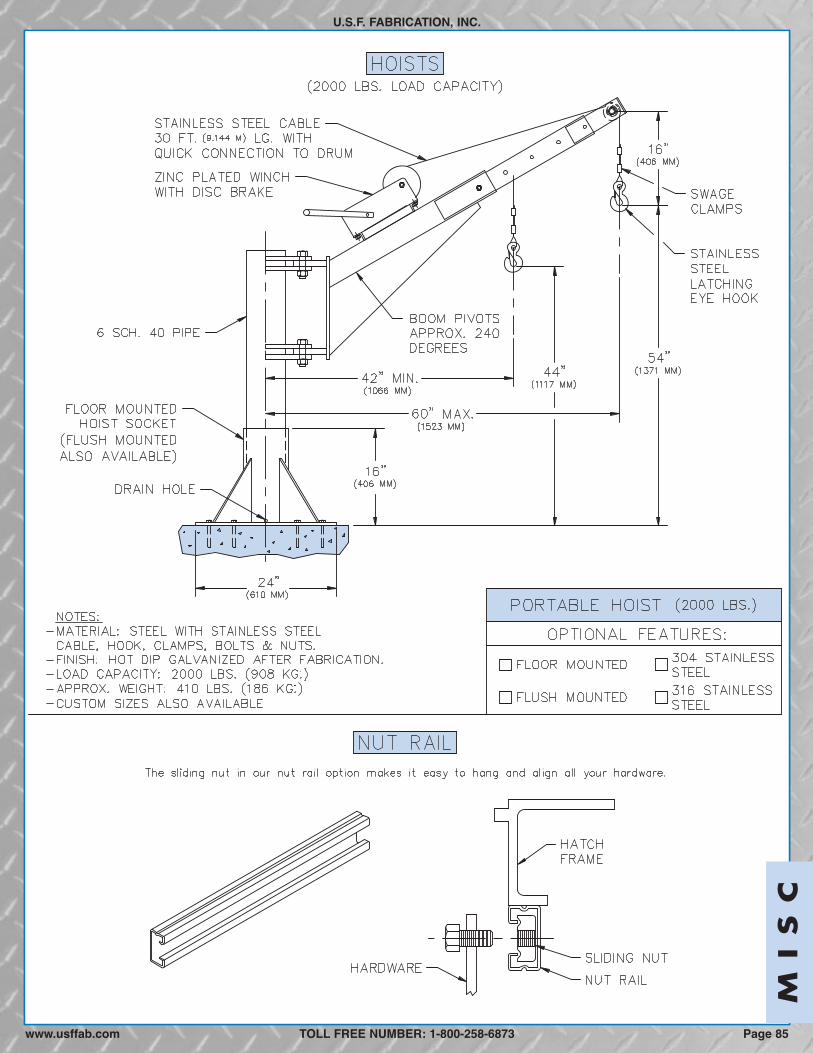
TOLL FREE NUMBER: 1-800-258-6873 Page 85www.usffab.com
U.S.F. FABRICATION, INC.
MI
SC

TOLL FREE NUMBER: 1-800-258-6873 www.usffab.comPage 86
U.S.F. FABRICATION, INC.M
IS
C

U.S.F. FABRICATION, INC.
TOLL FREE NUMBER: 1-800-258-6873 Page 87www.usffab.com
MI
SC
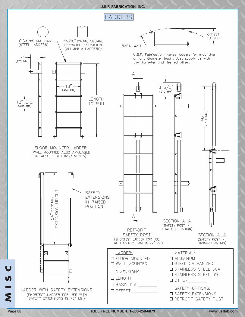
TOLL FREE NUMBER: 1-800-258-6873 www.usffab.comPage 88
U.S.F. FABRICATION, INC.M
IS
C

TOLL FREE NUMBER: 1-800-258-6873www.usffab.com Page 89
U.S.F. FABRICATION, INC.
MI
SC

U.S.F. FABRICATION, INC.
TOLL FREE NUMBER: 1-800-258-6873 www.usffab.comPage 90
MI
SC

U.S.F. FABRICATION, INC.
TOLL FREE NUMBER: 1-800-258-6873 Page 91www.usffab.com
MI
SC

INFORMATION REQUIREMENTS OF U.S.F. FABRICATION, INC.FOR
RETROFIT SAFETY NETS & GRATES
U.S.F. FABRICATION, INC.
Company:___________________________ Contact Person: ____________________Ph: _____________, Fx: _______________ Email: ____________________________
1. USFFab retrofit safety devices are designed for installation into existing openings where thedoor frame is already cast into concrete. Mark below which type device you want:___ Retrofit safety net ___ Retrofit grate
2. Rate the condition of the concrete where the safety net or grate will be installed.___ Good (no chipping or cracks) ___ Poor (chipping and/or cracks—provide photos)
3. What is the thickness in inches of the concrete slab? _________
4. If the hatch has two covers (i.e. double door), are the covers hinged on—___ Opposite sides of the frame (see hinge depiction in below sketch)___ Same side of frame (see hinge depiction in below sketch)
5. In appropriate sketch below—a. Enter the frameʼs inside A & B dimensions (Measure distance between opposite points
on frame that are flush with the concrete.)b. Show locations of any obstructions--e.g., guide rail brackets, cable holders, and etc.
(consider sending photos if necessary/helpful).
6. When the hatch is closed, mark below how the doorʼs springs extend:___ Vertically to cover ____ Horizontally with cover ____ No Springs
7. Indicate if the net or grate is for a: ____pump station ____valve box ____ other
8. For estimating freight cost, provide city, state and zip code of the shipping destination.___________________________________________________________________________
9. Contact the USFFab Customer Service Dept. (800-258-6873) for any of the following specialrequirements: (a) hatches with more than two covers, (b) insufficient concrete slap depth foranchoring angle supports, and (c) extra large openings.
Page 92 www.usffab.comTOLL FREE NUMBER: 1-800-258-6873