using 3-d scanner yu yang, todd sparks, jianzhong ruan...
TRANSCRIPT

LASER DEPOSITION CLADDING ON-LINE INSPECTION
USING 3-D SCANNER
Yu Yang, Todd Sparks, Jianzhong Ruan, Lan Ren, Frank Liou
University of Missouri – Rolla, Missouri, U.S.A 65401
Email: [email protected], [email protected]
ABSTRACT Reviewed, accepted August 23, 2007
Laser deposition directly deposits metal cladding to fabricate and repair components. In
order to finish the fabrication or repair, 3-D shape of the deposition needs to be inspected, and
thus it can be determined if it has sufficient cladding to fabricate a part after deposition process.
In the present hybrid system in the Laser Aided Manufacturing Lab (LAMP) at the University of
Missouri - Rolla, a CMM system is used to do the inspection. A CMM requires point-by-point
contact, which is time consuming and difficult to plan for an irregular deposition geometry. Also,
the CMM is a separate device, which requires removal of the part from the hybrid system, which
can induce fixture errors. The 3-D scanner is a non-contact tool to measure the 3-D shape of laser
deposition cladding which is fast and accurate. In this paper, A prototype non-contact 3-D
scanner approach has been implemented to inspect the free-form and complex parts built by laser
deposition. Registration of the measured model and 3-D CAD model allows
the comparison between the two models. It enables us to determine if the deposition is sufficient
before machining.
Keywords
Laser deposition, 3-D scanning, free form, part comparison, inspection
I. INTRODUCTION
Rapid prototype technologies are gaining more and more interests in industries for the
reasons that they can fabricate the components directly from 3-D computer-aided-design (CAD)
model and save time and cost as well. Laser deposition is a rapid prototype technology that can
directly build solid metal parts from metallic powder, such as Tool steel, Titanium, etc. One of
the advantages of laser deposition is that it can deposit free-form surfaces and complex
geometries. In the Laser Aided Manufacturing Processes (LAMP) lab at the University of
Missouri - Rolla, a hybrid system was developed to deposit metallic powder to build or repair a
part. After deposition, the hybrid system machines it to fabricate the part.
Examination of the deposition cladding indicates that the interdependence of laser power,
powder feed rate into the melt pool, relative traverse speed of the part and retained heat effects
cause difficulty in precisely controlling the deposition cladding profile [1]. So it is important to
inspect the deposition cladding. To verify the acceptance of a deposited component before it is
machined by CNC, one needs to compare the measured data with the intended CAD design
model to determine if it is sufficient to be manufactured into a component afterwards.
In the present hybrid system, a Coordinate Measuring Machine (CMM) system is used to
do inspection. Despite its great accuracy, CMMs have some drawbacks, for example, CMMs
need point by point contact inspection, they are slow and the probe size limits the smallest area
that can be inspected, which makes it difficult to inspect the complex geometry or free form
74
surface [2]. In this paper, a 3-D scanner is used to inspect the surface of the laser cladding. It is
fast and has sufficient accuracy for on-line inspection.
The main idea behind the research in this paper is to align the measured surface with the
3-D CAD model and then compare the two top surfaces. Before comparing measurement data to
the 3-D CAD model, it is necessary to align the model with the scan data. This process is called
registration, which is to transform the Scanner Coordinate System (SCS) and the Design
Coordinate System (WCS) into one coordinate system. Then the algorithm creates parallel planes
to slice both the 3-D CAD model and scanned model in the x and y directions. The intersections
of 3-D CAD and scanned model are calculated. The comparison of the 3-D CAD model with the
measurement model is transferred to compare these points and it will show the height difference
and then determine if the measured component is sufficient or not at a (x, y) position. Any absent
volume can be identified and re-deposited later.
II. Equipment overview
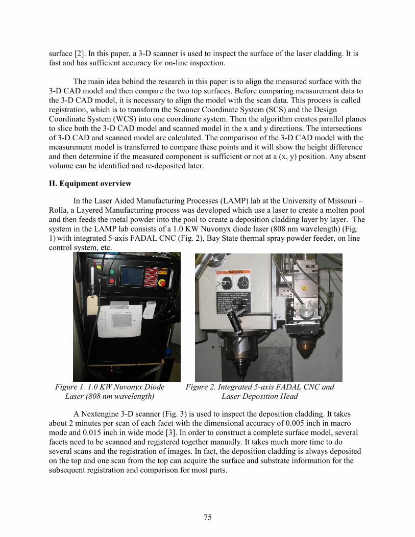
In the Laser Aided Manufacturing Processes (LAMP) lab at the University of Missouri –
Rolla, a Layered Manufacturing process was developed which use a laser to create a molten pool
and then feeds the metal powder into the pool to create a deposition cladding layer by layer. The
system in the LAMP lab consists of a 1.0 KW Nuvonyx diode laser (808 nm wavelength) (Fig.
1) with integrated 5-axis FADAL CNC (Fig. 2), Bay State thermal spray powder feeder, on line
control system, etc.
Figure 1. 1.0 KW Nuvonyx Diode
Laser (808 nm wavelength)
Figure 2. Integrated 5-axis FADAL CNC and
Laser Deposition Head
A Nextengine 3-D scanner (Fig. 3) is used to inspect the deposition cladding. It takes
about 2 minutes per scan of each facet with the dimensional accuracy of 0.005 inch in macro
mode and 0.015 inch in wide mode [3]. In order to construct a complete surface model, several
facets need to be scanned and registered together manually. It takes much more time to do
several scans and the registration of images. In fact, the deposition cladding is always deposited
on the top and one scan from the top can acquire the surface and substrate information for the
subsequent registration and comparison for most parts.
75

III. RELATED WORK
3.1. Registration
Traditionally, localization1 is achieved by presenting the part at a desired position and
orientation, using special tools, fixtures or some device especially designed for the part. It is
usually costly, time and efforts are needed to design the special fixture for a new part. Recently,
localization has been implemented by aligning the parts’ SCS to the DCS by using some
measured data [2].
Figure 3. A Nextengine 3-D scanner with 0.005 inch accuracy in
macro mode and 0.015 inch accuracy in wide mode
The 3-2-1 approach, which measure datums to establish a reference frame for the part, is
conventionally used in contact inspection. Three points are measured to establish the first plane,
then two points are measured from second plane perpendicular to the first. At last, one point is
measured from the last datum perpendicular to those two [2].
Figure 4. Traditional 3-2-1 approach for registration to
establish three perpendicular reference frames
The prevalent approach in registration is the Iterative Closest Point (ICP) method. ICP
tries to find the minimum distance between two surfaces [2]. It is effective to do point to model
1 In this paper, the term of “registration” is used instead of “localization” in references.
76
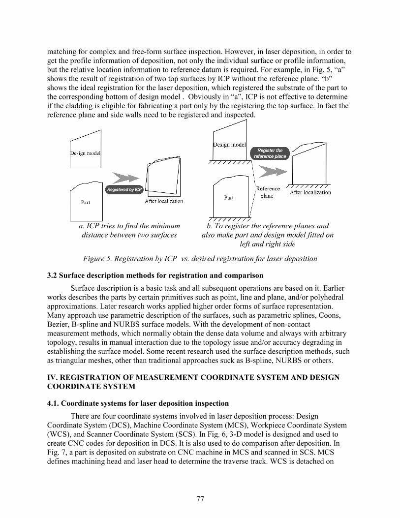
matching for complex and free-form surface inspection. However, in laser deposition, in order to
get the profile information of deposition, not only the individual surface or profile information,
but the relative location information to reference datum is required. For example, in Fig. 5, “a”
shows the result of registration of two top surfaces by ICP without the reference plane. “b”
shows the ideal registration for the laser deposition, which registered the substrate of the part to
the corresponding bottom of design model . Obviously in “a”, ICP is not effective to determine
if the cladding is eligible for fabricating a part only by the registering the top surface. In fact the
reference plane and side walls need to be registered and inspected.
a. ICP tries to find the minimum
distance between two surfaces
b. To register the reference planes and
also make part and design model fitted on
left and right side
Figure 5. Registration by ICP vs. desired registration for laser deposition
3.2 Surface description methods for registration and comparison
Surface description is a basic task and all subsequent operations are based on it. Earlier
works describes the parts by certain primitives such as point, line and plane, and/or polyhedral
approximations. Later research works applied higher order forms of surface representation.
Many approach use parametric description of the surfaces, such as parametric splines, Coons,
Bezier, B-spline and NURBS surface models. With the development of non-contact
measurement methods, which normally obtain the dense data volume and always with arbitrary
topology, results in manual interaction due to the topology issue and/or accuracy degrading in
establishing the surface model. Some recent research used the surface description methods, such
as triangular meshes, other than traditional approaches suck as B-spline, NURBS or others.
IV. REGISTRATION OF MEASUREMENT COORDINATE SYSTEM AND DESIGN
COORDINATE SYSTEM
4.1. Coordinate systems for laser deposition inspection
There are four coordinate systems involved in laser deposition process: Design
Coordinate System (DCS), Machine Coordinate System (MCS), Workpiece Coordinate System
(WCS), and Scanner Coordinate System (SCS). In Fig. 6, 3-D model is designed and used to
create CNC codes for deposition in DCS. It is also used to do comparison after deposition. In
Fig. 7, a part is deposited on substrate on CNC machine in MCS and scanned in SCS. MCS
defines machining head and laser head to determine the traverse track. WCS is detached on
77

Workpiece and is on the substrate. The zero points of x, y, and z axis of MCS is set on substrate.
The surface of substrate is adjusted to be level and the axes of WCS are set to be parallel to those
of MCS, so the deposition traverse track is parallel to the axes of WCS and the deposition layers
are parallel to the substrate. In order to compare the design model in Fig. 6 with the Workpiece
in Fig. 7, these two need to be registered. Three reference points A, B and C are created on the
substrate by laser flash. B is origin of MCS and AB is on the x axis of MCS. These reference
points have corresponding points A’, B’, and C’ on the design model, B’ is origin point of DCS
and A’B’ is on the x axis of DCS. The reference points are salient points and easily identified in
SCS and the scanned model is transferred to MCS through the points A, B, and C in 4.2. These
two models can be compared.
Figure 6. The 3-D CAD model created in Design Coordinate System (DCS)
Figure 7. Workpiece is deposited in Machine Coordinate System (MCS)
and scanned in Scanner Coordinate System (SCS)
4.2. Construct a coordinate system via three points
Locating a part’s DCS and SCS is called localization, which refers to the determination
of position and orientation of the DCS of a part with respect to the SCS. In this project, it is equal
to register a part’s SCS and MCS. Mathematically, it is to find a transformation matrix between
the two coordinate frames [2].
The registration is a transformation between two coordinate systems, for example:
transferring SCS to MCS, which is to find the matrix that transfer coordinates from o’x’y’z’ to
oxyz (Fig. 8). Suppose in SCS, the coordinate of origin O is (p’1, p’2, p’3), u1, u2, u3 denote x, y, z
axis and v1, v2, v3 denote x’, y’ z’ axis, then in SCS:
78

++=
++=
++=
3332321313
3232221212
3131121111
vvvu
vvvu
vvvu
γγγγγγγγγ
If
=
333231
232221
131211
γγγγγγγγγ
M
Figure 8. Mathematically, registration is to find the
transformation matrix between SCS and MCS.
(1) is denoted as:
=
3
2
1
3
2
1
v
v
v
M
u
u
u
An arbitrary point Q (q’1, q’2, q’3) in SCS denotes:
[ ] OQOO
v
v
v
qqqOQ +=
= ''''
3
2
1
321
[ ]
=
3
2
1
321 ''''
v
v
v
pppOO
So
[ ] [ ]
−=
3
2
1
321321 )''''''(
v
v
v
pppqqqOQ
According to (3):
(3)
(4)
(5)
(6)
(1)
(2)
79

[ ] [ ]
−= −
3
2
1
1
321321 )''''''(
u
u
u
MpppqqqOQ
So in SCS, an arbitrary point Q (q’1, q’2, q’3) can be transferred into MCS and coordinates are:
[ ] [ ] 1
321321 )''''''(−− Mpppqqq (8)
M-1 is the transform matrix and (p’1, p’2, p’3) is coordinates of origin O in the new coordinate
system MCS.
It is assumed that it is possible to have some salient points on the part or make some by
marks or other methods, and these points have corresponding points on the CAD model. After
scanning the surface, these points are carefully picked and the coordinates are collected on
screen. Then the coordinate system can be built by these points. Registration can have two steps:
find the point to point corresponding relationship between the measurement surface and design
surface, and then find the transformation matrix between these two surfaces to construct a
common coordinate system. Only three points are needed to build a coordinate system and get
the transform matrix. In practical applications, the points on the measurement and 3-D model
surfaces are not strictly corresponding and it needs adjustment to make them fit, for example, to
make the sum of squares of distance to be the least.
In this paper, a new three-point approach is introduced. For the reason that the 3-D
scanner can capture points on the surface precisely when zoomed in by the program, if there are
marks or salient points on the surface, the coordinate of points can be obtained and by zoomed in,
the error of on-screen point selection is about ±0.002 inch. One of the three points is the origin,
the second point and origin can determine x axis and z axis is parallel to the normal of plane of
A, B, C, these two axis can determine y axis exclusively. In Fig. 9, points A, B and C are both on
substrate. Point B is set to be origin in MCS and vector AB is on X axis. The coordinate system
can be determined in (9). The three points are on the reference plane in order to inspect the
surface relative to the reference plane. For example, the substrate is appropriate to be the
reference plane for the reason that the cladding deposited from it. In this paper, a substrate is
selected to be the reference plane. M-1 can be got from (9), and the coordinate of Q in MCS can
be got from (8).
×
×
××
×=
=
BCBA
BCBA
BA
BA
BCBA
BCBA
BA
BA
v
v
v
M
u
u
u
3
2
1
3
2
1
(9)
(7)
80

Figure 9. Three points approach to establish a coordinate
system by calculating the cross product of vectors
4.3. Error estimate
In Fig. 10, the coordinate systems xyz are created by A, B, C. The center of circle is the
point in MCS, r is the deviation of these points captured in SCS. For the reason of the 3 points
that are captured on screen could have errors, it leads to create deviation of SCS from MCS and
coordinates of surface have some errors after transformation from SCS to MCS.
The deviation of A, B, and C on the plane have no effect on “z” coordinates of Q, but x”
and “y” coordinate of Q can be affected. In Fig. 11, suppose the deviation of A, B, and C is “r”,
the points captured could be in the circle with the radius of “r”. Deviation of “x” coordinate can
be within ±r. Deviation of “y” is depend on the coordinate of “y”, besides the errors created by
the position of B, the error of point A create the angle of “θ ” , it causes the “x” axis departure an
angle “θ ”. So the extra error created by the angle “θ ” is scale to the “x” coordinate of Q and is
equal to. When do experiments, in order to reduce the error created from captured points, the
efforts are to reduce the distance of reference points A and B from point C and increase the
distance of A from B, so the error of transformation is less than 2r.
Figure 10. Errors of transformation from SCS to MCS, which is
resulted from deviation of point selections
point selections
81

Figure 11. Error analysis of x and y coordinates
for points A, B, and C on xoy plane
In Fig. 10, the coordinate systems xyz are created by points A, B, and C. The center of
circle is the point in MCS and r is the deviation of these points captured in SCS. For the reason
of the 3 points that are captured on screen could have errors, it leads to create deviation of SCS
from MCS and coordinates of surface have some errors in SCS from MCS. In order to estimate
the error r, six sample points are captured at each point of A, B in table 1. So r=0.002, it is higher
than the accuracy of 3-D scanner, the reason is that when measure the point on the screen, it is
interpolated on the triangular mesh so it is possible that it has higher resolution than that of the 3-
D scanner. The nominal distance of AB is 0.75 inch and the measurement of AB is 0.743±0.004
inch, the error is at the same level as that of 3-D scanner.
Table 1. Coordinates of points A and B
A B Point
Mean σ(STD) Mean σ(STD) x 1.357±0.002 1.4×10
-3 1.359±0.001 1.5×10
-3
y -1.944±0.001 1.2×10⁻³ -2.687±0.001 9×10
-4
z 0.164±0.001 1.6×10⁻⁵ 0.162±0.001 1.5×10
-5
If there is no error from the point selections, the accuracy of the coordinates after
transformation should keep the same as the accuracy of 3-D scanner, which is 0.005 inch. The
errors of the point selections will cause the coordinates changed within ±0.004. The overall
errors together with that of 3-D scanner, which is ±0.0025 inch, are the sums of the two: ±0.0065
or 0.013 inch.
V. COMPARISON BETWEEN THE MEASUREMENT SURFACE AND THE 3-D CAD
MODEL
5.1. Surface description
Stereo Lithography or Standard Triangulation Language (STL) is widely used in rapid
prototyping, STL model is a surface model based on triangular meshes. It makes the geometry
description homogenous and no matter how complex the shape is [4]. The drawbacks of STL
data format are the limited accuracy, the high data storage space needed and only the surface
model left without metadata. Despite the drawbacks, the importance of STL in CAD/CAM is still
82
increasing. The STL data format saves the 3-D model with triangular meshes for describing 3-D
surfaces. Each mesh contains a triangular data, which has its own 3 vertices coordinates and the
normal vector of the triangle. In order to process the vertices data and reduce the processing time,
all the triangular data are sorted and all the description letters are removed [5].
There are at least two reasons to use the STL data format within this domain of
comparing surfaces for complex shape. First, both 3-D scanner application software and the 3-D
modeling tools support STL model. It allows the comparison finished in one coordinate system
and data format. Second, a homogeneous STL model is fit for analysis complex (freeform)
surface since it hides the complex modeling history. Freeform shapes are created from advanced
operation in CAD, such as intersections, surface modeling operations, etc.
5.2. Algorithm for the comparison
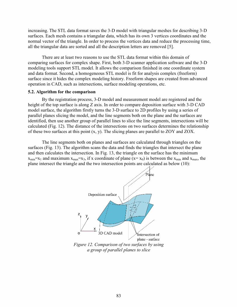
By the registration process, 3-D model and measurement model are registered and the
height of the top surface is along Z axis. In order to compare deposition surface with 3-D CAD
model surface, the algorithm firstly turns the 3-D surface to 2D profiles by using a series of
parallel planes slicing the model, and the line segments both on the plane and the surfaces are
identified, then use another group of parallel lines to slice the line segments, intersections will be
calculated (Fig. 12). The distance of the intersections on two surfaces determines the relationship
of these two surfaces at this point (x, y). The slicing planes are parallel to ZOY and ZOX.
The line segments both on planes and surfaces are calculated through triangles on the
surfaces (Fig. 13). The algorithm scans the data and finds the triangles that intersect the plane
and then calculates the intersection. In Fig. 13, the triangle on the surface has the minimum
xmin=x1 and maximum xmax=x3, if x coordinate of plane (x= x0) is between the xmin and xmax, the
plane intersect the triangle and the two intersection points are calculated as below (10):
Figure 12. Comparison of two surfaces by using
a group of parallel planes to slice
83

Figure 13. Intersections of plane and triangle
calculated by interpolation
−
−−+=
−
−−+=
)(
))((
)(
))((
13
101312
12
101211
XX
XXPPPQ
XX
XXPPPQ
(10)
One triangle intersects the plane x= x0 at a line segment, and all the lines segments
compose the profile that the plane intersects the surface. A group of parallel planes, which are
vertical to the previous ones, are created to slice the profiles in Fig. 14. S and T are the
intersection of line segments with parallel lines, which indicate the relative height z and distance
of these two surfaces at this point: x=x0, y=y0. S can be got:
)(
))((
12
10121
yy
yyQQQS
−
−−+= , and it is the same as T. In order to get higher resolution of the result,
more planes are needed to slice the model and get more points on the surfaces. Calculation
procedure for registration and comparison is as below in Fig. 15.
The algorithm proposed in this paper has been implemented on a PC and mainly written
in Matlab.
Figure 14. Intersections of planes and line segments
calculated by linear interpolation
84
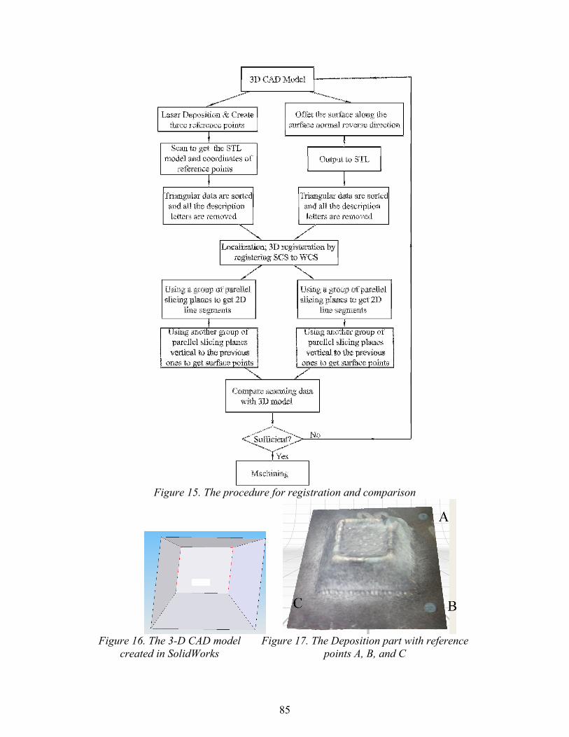
Figure 15. The procedure for registration and comparison
Figure 16. The 3-D CAD model
created in SolidWorks
Figure 17. The Deposition part with reference
points A, B, and C
85

Figure 18. Scanned model and design model, which are separated and in different
orientation before registration, can not be directly compared
VII. SUMMARY AND CONCLUSION
This paper describes how to compare the laser deposition surface and its target 3-D
model using a 3-D scanner to do a no-contact top surface measurement.
Based on the approach of registration and comparison algorithm, measurement data is
aligned with 3-D model, which needs three reference points, and the comparison between top
surfaces of deposition cladding and 3-D model is conducted. It determines if the deposition
cladding is sufficient for fabricating a part according to the comparison before machine the part.
The overall accuracy of this method is 0.013 inch and it fulfills the requirement of laser
deposition. The advantage of this method is that it is fast and convenient to inspect the deposition
cladding. The disadvantage is that it can not perform real-time inspection for environmental
condition. Also if the surface has steep curvature, a complete scanning model will be needed to
perform the comparison.
86

Figure 19. The scanned model and design model
are registered and comparable
ACKNOWLEDGEMENT
This research was supported by the National Science Foundation Grant Number DMI-
9871185, the grant from the U.S. Air Force Research Laboratory contract # FA8650-04-C-5704,
and UMR Intelligent Systems Center. Their support is greatly appreciated.
REFERENCES
1. E. Fearon, K.G. Watkins, “Optimization of Layer Height Control in Direct Laser Deposition”,
23rd International Congress on Application of Laser & Electro-Optics (ICALEO 2004) Paper
No. 1708
2. Huang X., and Gu P., “CAD-model based inspection of sculptured surfaces with datums”,
International Journal of Production Research, 36:5, 1351 – 1367.
3. https://www.nextengine.com/indexSecure.htm
4. Yadong Li, Peihua Gu, “Free-form surface inspection techniques state of the art review”,
Computer-aided Design, 36(2004) 1395-1417.
5. Pierre P. Lefebvre, Bert Lauwers, “STL model segmentation for multi-axis machining
operations planning”, Computer-aided Design and Application, Vol 1, P277-284.
6. Ren C. Luo et al., “Efficient 3-D CAD Model Slicing for Rapid Prototyping Manufacturing
Systems”, Industrial Electronics Society, 1999. IECON '99 Proceedings. The 25th Annual
Conference of the IEEE, p1504-1509 vol.3
87