using a quantum cascade laser analyzer to implement energy ... · refining and other industries a...
TRANSCRIPT

Distributed with permission of authors by ISA 2010 Presented at ISA Automation Week 2010 Houston Texas
Using a Quantum Cascade Laser Analyzer to
Implement Energy Savings in Combustion Control
AUTHOR CO-AUTHOR
Robert J. Bambeck President, CEO
Bambeck Systems Inc. Santa Ana, California
T: 949-250-3100 bambecksystems.com
Jason Mooney Process Engineer
Valero Houston Refinery Houston Texas
Cell: 832-293-3663
KEYWORDS Boiler Efficiency, Combustion Control, Flue Gas Analyzer, Quantum Cascade Laser, Fuel Optimization ABSTRACT A new analyzer technology provides the power utilities, industrial boiler plants, petrochemical, refining and other industries a combustion tool for the control of process heaters and boilers. The analyzer uses a single Quantum Cascade Laser (QCL) to measure and read ppm CO, %H2O, %CO2 and %O2 directly in combustion flue gas. This in-situ analyzer providing real-time combustion constituent data provides the opportunity to maximize fuel efficiency while eliminating unsafe CO levels. Applications available for the analyzer including combustion optimization for energy efficiency, safety monitoring, green house gas content and lowering emissions are discussed. An installation in a power utility electric generation plant boiler is described detailing the benefit resulting from achieving the ideal balance of low excess air and combustion produced CO. When incorporated as part of a Safety Instrumented System (SIS), the analyzer can be used as a monitor for high CO (precursor of combustibles) and low excess air measured as O2. Using a patented algorithm, the O2 measurement is impervious to outside air contamination and potential false readings. The Quantum Cascade Laser technology is discussed, detailing how it offers multi-gas measurements, high reliability, no drift, no calibration requirement, fast analysis and operation in the challenges of the industrial combustion environment which encompass high temperatures, corrosive gases, varying gas pressures, and particulate interferences.

Distributed with permission of authors by ISA 2010 Presented at ISA Automation Week 2010 Houston Texas
INTRODUCTION - BACKGROUND
The development of the analyzer was driven by the requirements for improved combustion control in industrial boilers, heaters and furnaces with an extremely reliable, low maintenance and fast response analyzers. A major combustion control approach and the primary application for this technology is to use CO as the combustion control process variable to achieve near stoichiometric combustion. Since an efficient combustion process produces a trace amount of CO, the use of a CO analysis can optimize the process and result in substantial fuel savings for plant operators. Excess Air (the additional % of stoichiometric air beyond that needed for complete combustion) is typically added to insure complete combustion of the fuel. Excess Air dilutes, by % volume, the products of combustion in the flue gas. If complete combustion could be assured alternately, for example, with CO based automatic combustion control, then excess air would not be needed. Current successful technology of CO control uses an across the flue gas measurement with a glow-bar light source, gas cell correlation negative filter spectrometer CO analyzer and a probe type analyzer for O2. A quantum leap in technology is now available. This new gas analyzer has been developed based on a Quantum Cascade Laser. It measures non-intrusively multi-gases in the products of combustion and meet the conventional common standard specifications required for combustion control applications including direct CO control. The Quantum Cascade Laser is an innovative and efficient technology to replace standard infrared light sources, allowing multi-gas specificity for detection and eliminating the need for multiple analyzers currently required for flue gas measurements.
The analyzer is designed to measure gas concentrations at normal atmospheric pressures after the combustion of fossil fuels. Flue gas consists primarily of N2, CO2 and H2O with small amounts of O2 and trace amounts of CO and NO. Also there is a small amount of water vapor carried through from the humidity in ambient combustion air. The analyzer measures CO, CO2 and H2O during the combustion process. Having knowledge of the ambient combustion air humidity and fuel inerts, the flue gas O2 is calculated accurately without knowledge of the fuel composition.1. The availability of the O2 analysis in the same light path as the CO measurement is significant. It assists in the familiarization and acceptance of operators to the stoichiometric combustion control technology. It gives the added confidence of an O2 measurement, which has been the conventional combustion flue gas measurement. CO and O2 measurements prove useful in fine-tuning the combustion process and are an excellent valuable process analysis tool for heater and boiler burner adjustment and as a tuning aid for complying with NOx regulations.

Distributed with permission of authors by ISA 2010 Presented at ISA Automation Week 2010 Houston Texas
ANALYZER TECHNOLOGY A laser is a natural methodology for an analyzer to measure combustion gases through the transmission of light across a flue gas duct or stack. The measurement must be accurate and reliable at the specific gas absorption wavelengths while being subjected to the harsh conditions industrial environments. The Quantum Cascade Laser is the only laser that fits the need. It emits energy in the mid-infrared where CO, has its fundamental absorption wavelengths (4.5 to 4.9 µm). CO2 and H2O also exhibit fundamental absorption wavelengths in this region. This laser provides the foundation for a useful multi-gas analyzer. One challenge is to match the absorption intensities with the expected measurement levels in the combustion gas. An additional challenge is to operate for extended un-attended periods in the harsh plant environment with temperature and random vibration extremes. The quantum cascade laser is designed into an analyzer that can be located in such ambient environmental conditions typically on a boiler duct or heater stack. Mounting can be at the top of the furnace box if an appropriate location and a representative sample can be obtained. PRINCIPLES OF ANALYSIS Lasers are based on the principle of Light Amplification by Stimulated Emission of Radiation (LASER). 2. Spontaneous Emission is produced when an electron in the laser medium is excited (quantum-energy level) with an external power source. It spontaneously decays and transitions into a lower energy level, releasing energy in the form of a photon, emitted in a random spatial direction. Stimulated Emission of Radiation is a quantum effect, where electrons, stimulated by incoming photons, with like frequencies, produce photons of equal frequency and energy, traveling in the same direction, amplifying the power of the incoming radiation.
An electron changing energy emits a photon. Incoming photon stimulates an excited electron to undergo a transition
and emit an additional photon.

Distributed with permission of authors by ISA 2010 Presented at ISA Automation Week 2010 Houston Texas
CONVENTIONAL SEMICONDUCTOR DIODE LASERS
Conventional semiconductor diode lasers are bipolar and emit electromagnetic radiation by the recombination of electron–hole pairs. A photon is emitted when an electron transitions from the semiconductor's conduction band and recombines with a hole in the valence band. Conduction electrons and holes are neutralized and annihilated after once recombining across the band gap and can emit no more photons. The energy of the photon, thus the emission wavelength of laser diodes is determined by the band gap of the semiconductor material.
Conventional diode laser analyzers for CO and O2 require a laser for each gas since their absorption lines are far removed from each other. QUANTUM CASCADE LASER APPLICABILITY
As the Quantum Cascade Laser moved from the research lab to industrial uses, the manufacturing became reliable and repeatable. They are the premier laser for absorption spectroscopy in the mid-infrared region an area which there are excellent measurable fundamental absorption lines with the appropriate relative absorption coefficients for the combustion flue gas concentrations of CO, CO2 and H2O. There are also no other interference absorption lines from combustion flue gas.
The quantum cascade laser has been subjected to accelerated life testing which demonstrate the laser power is typically expected to be reduced by approximately 30% in seven years. This energy degradation is acceptable for meeting the performance specification required of the analyzer. Thus the laser is expected to have a minimum seven year life.
QCL TECHNOLOGY
The Quantum Cascade Laser is a unique type of a semiconductor laser emitting mid-infrared light using intersubband transitions of specially constructed semiconductor structures. It is unipolar and operates based on quantum theory, with electrons repeatedly cascading through a series of quantum wells producing photons as it transitions energy levels. It has the ability to reach longer wavelength than conventional diode lasers and to be tuned over a larger range of wavelengths.
In a Quantum Cascade Laser, the wavelength of the emitted photon is a function of the geometry of the structure. With conventional diode lasers, the wavelength is a function of the material.

Distributed with permission of authors by ISA 2010 Presented at ISA Automation Week 2010 Houston Texas
QCL CONSTRUCTION The Quantum Cascade Laser is built out of semiconductor quantum structures that differ in a fundamental way from diode lasers. The semiconductor material layer thickness creating the quantum wells are designed to create the desired emission wavelength. In such a tight space, electrons take on properties explained by quantum physics. Confined electrons oscillate only at certain well defined frequencies.
There may be over 100 layers of semiconductor material which may be as small as 0.3nm (layers
of atoms). 3.
When applying an electric field, the overall downward trend of energy produces coherent photons of like kind
and wavelength. 3
The semiconductor gain material is constructed from a periodic series of thin layers of indium gallium arsenide sandwiched between layers of a material with a wider band gap, indium aluminum arsenide, forming a superlattice. The superlattice introduces a varying electric potential across the length of the device. This one-dimensional multiple quantum well confinement leads to the splitting of the band of permitted energies into discrete electronic subbands.
These layers of semiconductor material create quantum wells which constrain the electrons. When an electron is injected into the gain region, it undergoes a first transition between two sublevels of a quantum well then a non-radiative transition to the lowest energy sublevel. It then tunnels into the upper level of the next quantum well. Thus an electron changes frequency and emits a photon. The emission wavelength is determined by the quantum confinement created by the semiconductor material layer thicknesses. The advantage of the Quantum Cascade Laser in the analyzer is the reliability of producing the precise wavelengths consistently over a long period of time.
ABSORPTION SPECTROSCOPY
The analyzer is based on the direct absorption measurement technique which takes advantage of the fundamental absorption lines for the detection frequencies and is defined by the Beer-Lambert law which relates the absorption of light to the properties of the gas through which the light is traveling.

Distributed with permission of authors by ISA 2010 Presented at ISA Automation Week 2010 Houston Texas
This is a logarithmic dependence between the transmission of the light, its absorptivity, the gas concentration, and the distance the light travels (pathlength).
T = I / Io = e –a c l
Where:
T = Transmission, a = absorption coefficient, temperature related c = concentration l = pathlength
With absorption spectroscopy, the absolute concentration values of a gas can be obtained without calibration and corrections for interferences and drift. .
Wavelength (µm) vs. % Absorption 4.
Fundamental absorption wavelengths for the combustion gases of CO, CO2 and H2O are in the mid-Infrared, which makes the Quantum Cascade Laser the natural fit for the analysis.
MEASUREMENT TECHNIQUE WITH THE QCL The laser controller applies 10 to 30 ns pulses of drive current to the laser, while providing a varying bias current forcing a shift in emission wavelengths. The laser controller tunes the laser sequentially across the set of three gas absorption wavelengths, plus a fourth reference wavelength that consists of full transmission (no absorption by the flue gas). This is done in a precise manor to continuously have knowledge of the wavelength location thus the gas measurement. The laser power is cycled to identify a new sweep. Light variations from the flue gas opaqueness are continuously adjusted in the digital signal processing. During each sequence of analysis the full transmission intensity is used for resetting from variances in gas opaqueness. This allows the measurement to remain within instrument specifications through exceptionally large laser light variations. The gas concentration is calibrated by ratioing the amplitude of the absorption line to the intensity of full transmission. The absorption intensity of a gas at a known pressure and temperature is defined by the laws of physics thus once set up no need exists for additional calibration.
Distributed with permission of authors by ISA 2010 Presented at ISA Automation Week 2010 Houston Texas
PRINCIPLES OF THE O2 CALCULATION Flue gas %O2 volume is obtained from CO2, CO and H2O measurements in the combustion process without knowledge of the fuel composition and no ambient air interference with the measurement. STOICHIOMETRIC COMBUSTION The composition of fuel is primarily Carbon and Hydrogen. After combustion, all Carbons in the fuel go to CO2 and CO in the flue gas and all Hydrogen's in the fuel go to H2O in the flue gas. This is regardless of in what combination or order they originate from the fuel. The stoichiometric combustion general equation (CmHn + (m+n/4)O2 + 3.774(m+n/4)N2 = mCO2 + (n/2)H2O + 3.774(m+n/4)N2 can be used to determine the molecules of CO2 and H2O that are to be present in the flue gas under stoichiometric conditions.
The analyzer measures %CO2, ppmCO and %H2O concentrations by volume of the flue gas. Ambient air humidity and temperature are measured and % water vapor in the combustion air is determined. Fuel Inerts of %Nitrogen, %Carbon Dioxide and %Water Vapor are input to the analyzer signal processing, as variables. Humidity %H2O is deducted from the %H2O measurement as are the fuel inerts. And since all the Carbon and all the Hydrogen in the flue gas came from the fuel, the C:H ratio of the fuel will be the same as the C:H ratio of the flue gas. Since the ratio does not change regardless of the dilution, the C:H ratio will determine the Carbon and Hydrogen composition of the fuel that was burned. Therefore, the fuel C:H ratio is determined by ratioing the CO, CO2 and H2O from the flue gas analysis. Since each molecule, regardless of the temperature or pressure, occupies the same volume as any other molecule no matter what is in each molecule and all measurements and calculations are in % volume, the percentage by volume of CO2 that should be in the flue gas under stoichiometric conditions can be determined by applying Charles' ideal gas law equation PV = nRT. Balancing stoichiometric equations for the fuel C:H ratio produces the stoichiometric percentage by volume of CO2 for any fuel being burned at any given time. By comparing the absolute measured %CO2 with stoichiometric %CO2, the variance will produce the %Flue Gas Dilution (%FGD). Calculation to determine the volume %O2 from the %FGD:
%FGD = %O2 *100*(1+ %H2OHumity + %Fuel + Ratio% + %FI) / (20.947 - %O2)
Solving for %O2
Distributed with permission of authors by ISA 2010 Presented at ISA Automation Week 2010 Houston Texas
Where: Combustion Air consists of Nitrogen, Oxygen and trace gases. The trace gases act as inerts, are combined with Nitrogen and considered a pass through. %Fuel = Volumetric ratio of stoichiometric fuel to combustion air. Typically 7.8% Ratio% = Ratio of Flue Gas Volume to total Incoming Air & Fuel Volume. Typically 1.8% %FI = Fuel Inerts by volume. Total %N2, %H2O and %CO2 in the fuel. Typically 2.5%
%FGD = %O2 (1+ %H2OHum + %Fuel + Ratio% + %FI)/(20.947 - %O2) %FGD x (20.947 - %O2) = %O2 + %O2 x %H2OHum + %O2 x %Fuel + %O2 x Ratio% + %O2 x %FI (%FGD x 20.947) - (%O2 x %FGD) = %O2 + %O2 x %H2OHum + %O2 x %Fuel + %O2 x Ratio% + %O2 x %FI %FGD x 20.947 = %O2 x (1 + %FGD + %H2OHum + %Fuel + Ratio% + %FI) %O2 = %FGD x 20.947/(1+%FGD + %H2OHum + %Fuel + Ratio% + %FI) Flue gas O2 measurement is therefore derived from the flue gas measured CO2, CO and H2O through the Carbon / Hydrogen ratio. ADVANTAGES OF THE TECHNOLOGY Advantages of the quantum cascade laser lie in the inherent long-term stability with no drift and thus requiring no calibration or adjustments. It produces consistent wavelengths when excited with a consistent current and held at a precise temperature. The wavelength is determined by the material layer spacing, a physical unchangeable characteristic and the principals of quantum physics which do not change with time.
The quantum cascade laser can be reliably tuned between the primary fundamental wavelengths of CO, CO2 and H2O allowing multi-gas capability with one laser analyzer thus a cost effective installation. ANALYZER FEATURES
The analysis is made optically with a single pass laser light beam transversing the flue gas from laser to detector without coming in physical contact with the gas. This in-situ measurement is made with infrared absorption spectroscopy completely across the flue duct giving a true cross section reading of the gas concentration. This is advantageous since the combustion from multi-burners is non-uniform throughout the furnace and the resultant flue gases are inherently stratified as combustion is completed. This technique provides a more representative sample than single sample points of measurement. There are no probes in the flue gas and there is no need for gas sample transport lines or a gas drying system. Measurements are reported on a wet (as is) basis. The laser light beam is impervious to vibration of the instrument and is not affected by expansion, contraction and movement of the stack or flue gas duct, sometimes referred to as oil canning, which can have a significantly negative influence on light beam analyzers. This effect is addressed by optical

Distributed with permission of authors by ISA 2010 Presented at ISA Automation Week 2010 Houston Texas
design of the mirrors to diverge and focus the beam, allowing sufficient light to always reach the detector. No moving parts are required in the analyzer aside from the air purge blowers and fans circulating internal air in the Instrument Enclosures for consistent temperature regulation. The Laser and Detector are completely solid state. The patented 1. technique for reading O2 eliminates the need for nitrogen purge, required of conventional diode laser O2 analyzers, to negate the effect of having air with 20.947% O2 present in portions of the analyzer external to the measurement flue gas path while trying to read 1 to 4% O2 in the flue gas. Fast response time is critical in applications when CO is used in combustion control. As stoichiometric combustion is approached, CO increases rapidly with slight reductions in excess air. The analyzer has a fast response speed to combustion flue gas composition changes. The analytical method acquires the CO signal in less than a second producing updates to the control system with sufficient time to identify a combustion issue before it becomes a problem.
DESCRIPTION OF THE ANALYZER
The Analyzer consists of two Instrument Enclosures, one for the Laser and one the Detector, located at the flue gas measurement area and a Transmitter located at grade. The Instrument Enclosures each have built-in Purge Air Blower Systems and are installed diametrically opposed on each side of the flue duct. They are bolted rigidly on 4” - 150 lb standard flanges which are welded to pipe stubs protruding through the duct wall. A high temperature insulating rigid gasket isolates the instrument mating flange reducing heat transfer from the flue gas. AC power is required to each side with 2 pair twisted and shielded interconnect cable from the Detector to the Transmitter. An Environmental Enclosure encases each Instrument Enclosure and its Purge Air Blower Systems. The enclosures act as a sun and rain shield providing weather protection from the industrial environment. Optical windows isolate and protect the Laser and Detector from the flue gas. They are designed to negate the laser etalon effect. Windows are accessible on a sealed slider for observation and cleaning, if necessary, without obstructing the optical alignment. Cleaning frequency depends on the cleanliness of the ambient air surrounding the analyzer. The Purge Air Blower Systems brings ambient air in through the bottom of the Environmental Enclosure and circulates it to the top of the Instrument Enclosure where an intake manifold pulls in the air for purge duty. The blower exhausts into the stack through the interconnect chamber between the Optical Window and the flue gas thus protecting the laser and detector windows from flue gas exposure and defining the specific flue gas measurement path length. In the process the purge air cools

Distributed with permission of authors by ISA 2010 Presented at ISA Automation Week 2010 Houston Texas
the Instrument Enclosure by circulating incoming ambient air and provides cooling of the connection interface of the instrument enclosure to the hot flue gas and mounting walls. Solid state air purge detection is incorporated to sense, alarm and shutdown the analyzer when the air purge has failed, protecting the analyzer from false readings and damage upon loss of purge. The built-in blowers alleviate the need for plant supplied instrument air for continuous purge. Optical mirrors are used for securing the laser – detector alignment. Adjustments are made on these internal focusing mirrors protected from normal industrial environmental corrosion and degradation. A red laser Visual Alignment Fixture is used to obtain spatial position and alignment of the laser beam. It is interchangeable on a slide in tray with the laser to use for visual optical alignment. This is required since the Quantum Cascade Laser produces very narrow emissions which are invisible to the naked eye. The Visual Alignment Fixture allows for initial or at will verification of optical alignment.
The Transmitter provides local readouts of the gas concentrations, setup parameters and other process information. Complete analyzer diagnostics, averages and fault histories also are available. The Transmitter is located in the instrumentation room. 4-20mA signal loops transmit signals to the DCS I/O interface cabinet for each gas, flue gas temperature and the common trouble alarm.
Flue Gas

Distributed with permission of authors by ISA 2010 Presented at ISA Automation Week 2010 Houston Texas
DESIGN OF THE LASER AND DETECTOR The laser beam is focused across the flue gas by an alignment mirror and is collected on the detector by a focusing mirror mounted internal to the Instrument Enclosures. The Quantum Cascade Laser is mounted on a thermoelectric cooler and is encapsulated with a collimating lens and hermetically sealed. The base is connected through a heat sink directly to the laser controller board inside a temperature insulated assembly. The laser is designed and manufactured specifically for measuring the absorption wavelengths of the basic combustion gases with line width sufficiently narrow enough to allow no other gas interference absorptions within significant adjacent wave numbers. It operates in the nominal ambient temperature range of the plant environment, commonly known as “room temperature”, being completely solid state with no moving parts, such as gratings or servo alignment motors.
The Detector is a Lead Salt semiconductor with a fast, highly sensitive response to the specific absorption wavelengths. It is mounted similar to the laser. In the optical path is a narrow band pass filter, uniquely designed to limit the wavelength transmission entering the detector, facilitating a high signal to noise ratio signal.
The Detector Controller board contains the detector controller and thermoelectric cooler controller. A digital signal transmission interface is used for communications with the Transmitter.
Digital Signal Processing required for producing gas measurement concentrations, is contained in the detector controller. Absorption lines of each gas are resolved with high speed selective spectral wavelength electronic tuning.
APPLICATION OF THE TECHNOLOGY The technology is applied to a natural draft refinery crude heater in Houston Texas. The heater has approximately a 200mmBtu firing rate in two boxes with a common convection section. There are two stacks with a QCL analyzer on each stack. The heater is over 20 years old. PROCESS DETAIL The Analyzer is beamed across the stack diameter six feet above the common convection section. The measurement pathlength is 8 feet each. The stack gas temperature ranges from 650 to 750 degrees F. Ambient conditions of the application range from 80 to 135 degrees F.
Distributed with permission of authors by ISA 2010 Presented at ISA Automation Week 2010 Houston Texas
INSTRUMENT SPECIFICS Since the analyzer is designed to measure combustion flue gas, the measurement ranges and response time from a process change of the gases are those to be expected only while combustion occurs:
CO 0 - 1000 ppm < 0.5 sec. response time CO2 5 - 20 % ~ 5.0 sec. response time H2O 5 - 20 % ~ 5.0 sec. response time O2 0 - 18 % ~ 5.0 sec. response time
The accuracy and repeatability is less than 1% of measurement.
RESULTS
• Safely lower furnace O2
• 1-5% efficiency improvement
• 10-40% NOx reduction
• 1-5% CO2 reduction
• ½ to 2 year payback
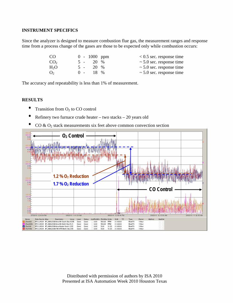
• Transition from O2 to CO control
• Refinery two furnace crude heater – two stacks – 20 years old
• CO & O2 stack measurements six feet above common convection section
O2 Control
CO Control
1.2 % O2 Reduction 1.7 % O2 Reduction

Distributed with permission of authors by ISA 2010 Presented at ISA Automation Week 2010 Houston Texas
SUMMARY The system operates as expected with the fast laser measurement feed-back critical to the implementation of CO control. ACKNOWLEDGMENTS Alpes Lasers Boston Electronics REFERENCES 1. U.S. Patent No. 7,414,726 2. Albert Einstein 3. Alpes Lasers 4. Daylight Solutions