using case tools object model design geodatabase and
TRANSCRIPT

Geodatabase andObject Model DesignUsing CASE Tools
Julio AndradeErik Hoel

Goals• Develop an understanding of
– when to use CASE versus ArcCatalog– how to represent data models in UML– how to run the schema wizard
• How to proceed forward– other UC’00 sessions– literature

• What is CASE• Database design• ArcInfo 8 Geodatabase• Representing the Geodatabase using
UML• Running the schema wizard• Demo
Agenda

What is CASE?

CASE• Computer Aided Software
Engineering• Used to specify data / object models
– classes / components (software)– database schemas
• Graphic modeling languages– historical - OMT, Booch, ER– current - UML

CASE• Commercial products
– Visio Enterprise– Rational Rose– Paradigm Plus (CA)– Popkin System Architect
• ArcInfo 8 requirements– support for UML– support for Microsoft Repository

Database Design

Continuum ofDatabase Design• Natively utilize Coverages and
Shapefiles• Import data into the Geodatabase• Utilize ArcCatalog to refine and
extend existing classes• Use CASE and UML for a ground-up
redesign of a large system

CASE Wizardsvs. ArcCatalog• ArcCatalog
– excels at tactical modifications– intended for modest models– user difficulty with large complex models
• CASE Wizards and UML– a strategic approach– very good for total system redesign– intended for maintaining complex models– learning curve for CASE tools and UML

ArcInfo 8Geodatabase

• A new object-oriented geographic datamodel
• All relational data storage using ArcSDE• Versioning and long transactions• New data access objects for application
software developers• Component based technology for
developing custom objects and features
ArcInfo 8 Geodatabase

• Dimension features• Enhanced support for custom features in
the editor• Dynamic segmentation• Direct import/export of geodatabase data• New connectivity rule• CASE tools enhancements• Performance enhancements
New Features at 8.1

Geodatabase Elements• Objects, object classes• Features, feature classes• Relationships, relationship
classes• Geometric networks• Feature datasets• Validation rules, domains• Spatial references• Rasters and other dataset
types in the future
Geodatabase
Feature datasets
Spatial reference
Geometric networks
Planar topologies
Domains
Raster datasets
Rasters
Feature classes, subtypes
Object classes, subtypes
Relationship classes
can beinside oroutside
of featuredatasets

Objects
• Objects: entitieswith properties and behavior
• An object is an instance of anobject class
• All objects in an object class havethe same properties and behavior
• An object can be related to otherobjects via relationships
A row storesan Object
NameOID Address . . .518 Bob 38 Oak St.
OWNER
A table storesan ObjectClass

Features• A feature is a
spatial object• Features have location
– a spatial attribute of type geometry
• Features can participate in network andtopological relationships
• A feature class is an object class thatstores spatial objects (features)
• All features in a feature class have thesame spatial reference
Feature(row)
ShapeOID524 X,Y,Z,M, ...
PARCELTypePrivate
. . .
. . .
FeatureClass (table)

Feature Datasets• Container for feature classes
– shared spatial reference• Analogous to a coverage
– less restrictive• May also contain
– relationship classes– geometric networks

Validation Rules• Store attribute, connectivity and
spatial rules on objects as part ofthe geodatabase
• Pre-defined, parameter driven:– attribute range rule– attribute set rule– connectivity rule
• Perform custom validation bywriting code

Domains• Describe the legal values of a field type
– used to ensure attribute integrity• Can be shared among classes• Uniquely named• Types of domains
– range• a tree can have a height between 0 and 300 feet• a road can have between 1 and 8 lanes
– coded value (e.g., a set)• a tree can be of type oak, redwood, or palm• a road can be made of dirt, asphalt, or concrete

Subtypes• Partition the objects in an object class
into like groups• Defined by the value of a subtype code
field• All subtypes:
– have the same attribute schema– have the same behavior schema– can have different default values and domains for
each field fid geom subtype width lanes name
103 asphalt 75.9 4 Calle Petra
101 asphalt 85.3 4 Chimayo Highway102 concrete 45.1 2 Acequia de Isabel
104 gravel 35.2 2 Maximilian Road

Relationship Classes• A relationship class is an association
between two object classes• Relationship classes may be 1:1, 1:n, n:m• An object class may participate in
multiple relationship classes• Related objects can message each other
– origin to destination, destination to origin,both, neither
– can trigger behavior (cascade delete, move tofollow, custom…)

Annotation• An example of a graphic feature class• Annotation feature classes may be
– feature-linked– non feature-linked
• Composite relationship manages link• Can store text as well as other graphics
– lines, arrows, boxes, etc.
feature class annotation featureclass
compositerelationship class
Majuro
Panape
Bora Bora
94 Majuro
95 Panape
92 Bora Bora41434749
929594
414347
212327

Dimension Features• Type of annotation that displays
specific distances on a map• Stored in a dimension feature class• Graphic feature• “Smart” feature
– special drawing– special editing
10.5 '

Geometric Networks• Used to model network systems• Topological relationship between feature
classes• Each feature class has a topological role
in the network (i.e., junction or edge)• A network may have multiple feature
classes in the same topological role• Topology based upon geometric
coincidence, always live• Feature classes must be in the same
feature dataset

Network Feature Classes• Network features live in a geometric
network• Directly support network analysis• Types:
– simple junction– simple edge– complex junction– complex edge
• Integrity constraint:– edge must have a junction at each endpoint
Edge Junction2..**

Connectivity Rules• Help you maintain a valid network• Constrain permissible connectivity
– default GN behavior allows any edgeto connect to any junction
• Connectivity rules include:– edge-junction rules
• cardinality– edge-edge rules
• permissible junction types• default junction type

• True dynamic segmentation (DynSeg)– display table or route events as layer in Map– interactively find a location along a route
• Event tables can be INFO, DBASE,Geodatabase, or OLE DB
• Route data canbe coverage routesystem, PolyLineMShapefile, orPolyLineM featureclass
Dynamic Segmentation
Route A
Route C
Route B
Route D
Route E

Planar Topology• Feature classes in an integrated feature
dataset participate in a planar topology• Features share boundaries• Editor tools allow you to edit and
maintain shared boundaries• Use the Integrate command in the
Editor to ensure coincident boundaries• Use shared edge edit tool to edit
shared boundaries and maintaintopological relationships

Versions• Object classes, feature classes, relationship
classes, geometric and logical networks mayall be versioned
• A version spans all multi-versioned objects inthe database
• Schema is constant across all versions• Versions differ only in those features or rows
or elements modified in each version• A user can connect to and
work with any version of thedatabase - majority will workwith the Default version
default
version1 version2
version3

Multi-Versioned Database
Default:Default:As BuiltAs Built
User1User1User1
User2User2User2
User3User3User3
Version:Version:Plan 1Plan 1
User4User4User4
User5User5User5
Version:Version:Design 1Design 1
User6User6User6
Version:Version:Design 2Design 2
Electric NetElectric Net

Representing theGeodatabaseUsing UML

Data Modeling Process
CodeGeneration
MSRepository
SchemaCreation
3rd PartyCASE Tool
UML ObjectModel
Building
LandBase.DLL
Geodatabase
Building FClass
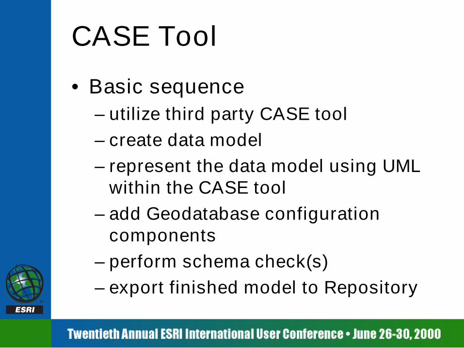
CASE Tool• Basic sequence
– utilize third party CASE tool– create data model– represent the data model using UML
within the CASE tool– add Geodatabase configuration
components– perform schema check(s)– export finished model to Repository

UML Review• Unified Modeling Language
– lingua franca of object modeling• Developed in 1997 as a unification
of the three leading methodologies– OMT (Rumbaugh)– Booch– Jacobson (use cases)

UML Syntax
Superclass
Property1Property2
Subclass1Property3
<<stereotype>>Subclass2
Property4Property5
Inheritance Relationships
Class1 Class2
Association
Class1 Class2
Composition
Method1()
Class1 <<interface>>IClass1
Realization
For Arc8, this is 90% of what you need to know with respect to UML

Properties
• Properties become fields in schema• Model the feature
– feature class will be automatically created inthe GDB during schema generation
Building
+Owner:esriFTString+Height:esriFTDouble
OID Shape Owner Height
Building
Feature

Methods
<<Interface>>IBuilding
+BuiltIn: DATE+Height: double
Building
• Methods always live in the interface– components are interface-based– class realizes an interface
Note: this is necessary only for source code generation
+Owner:esriFTString+Height:esriFTDouble
+Age(): double+AvgWaterUse(year:long):double

Object Model Sample
SecondaryCircuitPrimaryCircuit
Building
Feature
CircuitXformerMeter
SimpleEdgeSimpleJunction
NetworkFeature
JunctionFeature EdgeFeature
Object
Tennant ObjectClass
FeatureClass
FeatureClassand Geometric
Network
ESRI Feature
User Feature

Feature Datasets
<<FeatureDataset>>SNLandbase
• New for 8.1• Feature datasets correspond to
stereotyped packages in UML• Feature classes and geometric networks
added to package (tree view)

Feature Datasets• Modeling feature datasets as packages
enables:– stand-alone feature classes– relationship classes between feature classes
in different feature datasets– specification of coordinate systems within
the schema generation wizard– default coordinate systems (last specified)

Geometric Networks
<<GeometricNetwork>>ElectricNetwork
+NetworkType: esriNetworkType=esriNTUtilityNetwork
Primaries
• New for 8.1• Modeled as a stereotyped class
associated with all feature classes inthe network
Secondaries
Transformers

Subtypes
• Subtypes based on single integer field• UML Association named “Subtype”• Default subtype
Building
+<<SubtypeField>>Kind:esriFTInteger=2+Owner:esriFTString+Height:esriFTDouble
Tall Building+Kind:esriFTInteger = 1
Short Building+Kind:esriFTInteger = 2
SubtypeSubtype

Default Values
• Assigned on a subtype basis
Building
+<<SubtypeField>>Kind:esriFTInteger=2+Owner:esriFTString+Height:esriFTDouble
Tall Building+Kind:esriFTInteger = 1+Owner:esriFTString = “The Donald”+Height:esriFTDouble = 500
Short Building
+Kind:esriFTInteger = 2+Owner:esriFTString = “Joe Schmo”
SubtypeSubtype

Domains
• Stereotyped class• Side effect creates an attribute rule
Building
+<<SubtypeField>>Kind:esriFTInteger=2+Owner:esriFTString+Height:esriFTDouble
BuildingTall+Kind:esriFTInteger = 1+Owner:esriFTString = “The Donald”+Height:BuildingHeights = 500
BuildingShort
+Kind:esriFTInteger = 2+Owner:esriFTString = “Schmo”
<<RangeDomain>>BuildingHeights
+FieldType: esriFTdouble+MergePolicy: -+SplitPolicy: -+MinValue: = 0+MaxValue: = 750
SubtypeSubtype
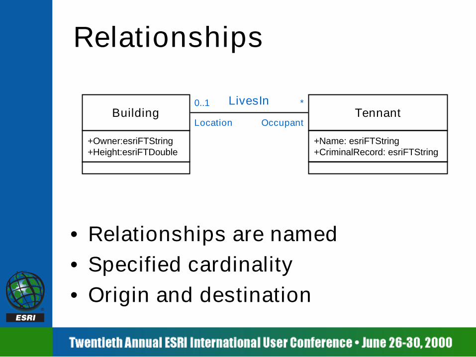
Relationships
Tennant
+Name: esriFTString+CriminalRecord: esriFTString
• Relationships are named• Specified cardinality• Origin and destination
+Owner:esriFTString+Height:esriFTDouble
BuildingLivesIn
Location Occupant
0..1 *

Attributed Relationships
• A separate table will be created• Not restricted to many to many
relationships• Specified as a UML class
– named after the UML association– stereotyped as <<RelationshipClass>>
<<RelationshipClass>>LivesIn
TenantSince:esriFTDate
Tennant
+Name: esriFTString+CriminalRecord: esriFTString
+Owner:esriFTString+Height:esriFTDouble
BuildingLivesIn
Location Occupant
0..1 *

Composite Relationships
• Part lifetime controlled by wholeclass (deep delete semantics)
• Always one to many
SwitchBank SwitchBankHasSwitch

Relationship Rules
• Assigned by subtypes• Same name as relationship• More specific cardinality
– but consistent with relationship
Tall Building ST Good Tennant STLivesIn
0..1 300

ConnRule
Connectivity Rules
• Edge connectivity rules– n-ary UML association
• Junction connectivity rules
EdgeST1 EdgeST2
JunctionST3ConnRule
JunctionST1
Default
JunctionST3
EdgeST1

Schema Wizard

Data Modeling Process
CodeGeneration
MSRepository
SchemaCreation
3rd PartyCASE Tool
UML ObjectModel
Building
LandBase.DLL
Geodatabase
Building FClass

Schema Wizard• Basic sequence
– start wizard from within ArcCatalog– connect to the Repository, select the model– select the feature dataset to generate the
schema for• all domains are created at this time• relationship classes only created if feature class is
also being created
– define schema properties for each feature– generate schema when closing wizard

Semantics Checker• New for 8.1• Check a model exported to the
Repository– reports ALL errors at once– shortens modeling cycle
• Add-on that runs inside Visio• Should be run before the schema or
code generation wizards

Startling Demo

Background Info:Orphan Junctions• Simple junction feature• Automatically added when first
feature class added to network<networkName>_Junctions
• Integrity constraint:– edge must have a junction at each
endpointEdge Junction
2..**
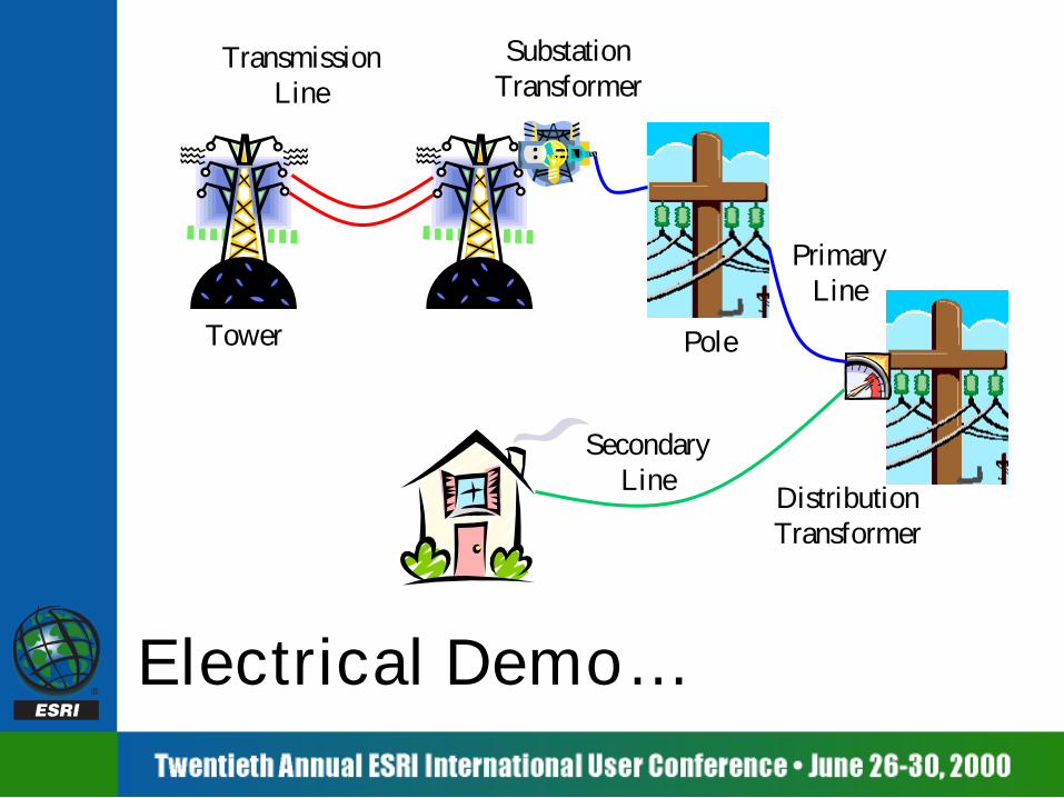
Electrical Demo…
Tower
SubstationTransformer
Pole
PrimaryLine
DistributionTransformer
TransmissionLine
SecondaryLine

Conclusions• Time spent data modeling is very
beneficial in the long run• Pay attention to performance issues• Use ArcCatalog for tactical control of
simpler systems• Use CASE (UML and schema wizard) for
modeling complex systems• Both tools will simplify your life

For Further Info

For Further Info• Relevant UC sessions:
– Overview of the Geodatabase– Designing and Using a Geodatabase– Working with a Versioned Geodatabase– Extending the Geodatabase with Custom
Objects– Extending the Geodatabase with Class
Extensions– Advanced Customization with ArcObjects in
C++– Managing and Editing Geometric Networks– Working with Networks in ArcInfo 8

For Further Info• Geodatabase Literature
– Michael Zeiler. Modeling Our World: the ESRI Guide toGeodatabase Design. ESRI Press, 1999.
– Andy MacDonald. Building a Geodatabase. ESRI Press,1999.
– Multi-user GIS Systems with ArcInfo 8. ArcOnline WhitePaper, March 2000.
– Erik Hoel, Julio Andrade, and Sudhakar Menon.Modeling GIS Databases Using UML. Submitted to the8th International Symposium of ACM GIS.

For Further Info• General Literature
– David Taylor. Object Technology: AManager’s Guide. 2nd Ed., Addison-Wesley,1997.
– Martin Fowler, et.al. UML Distilled: Applyingthe Standard Object Modeling Language.Addison-Wesley, 1997.
– Bertrand Meyer. Object-Oriented SoftwareConstruction. Prentice Hall, 1997.


Representing the GeoDatabaseusing UML
Representing the GeoDatabaseusing UML

Startling CASE Tool DemoStartling CASE Tool Demo

Hi-Tech Schema Wizard DemoHi-Tech Schema Wizard Demo