using gnss to establish a height datum on a project · 2009-08-17 · using gnss to establish a...
TRANSCRIPT

43rd Association of Surveyors PNG Congress, Lae, 12th - 15th August 2009Focus On Challenges; Society-Space-Surveyors
Using GNSS to establish a Height Datum on a ProjectRichard Stanaway, Quickclose
Using GNSS to establish a Height Datum on a Project
Richard StanawayQuickclose
PO Box 1364 Carlton VIC 3053 Australiaemail: [email protected]
Abstract
This paper explains in detail practical steps for establishing or extending a height datumon a project in PNG using GNSS Techniques, using recent surveys in PNG as examples.The following topics will be covered in the presentation:
1. An overview of the PNG, EGM96 and new EGM2008 geoid models2. Preliminary tidal monitoring and determination of MSL, LAT and HAT3. Using GNSS and PPP methods to estimate ellipsoid heights4. Estimating the geoid zero-order term (correction)5. Aligning a geoid profile with a pre-established height datum6. Height datum conversions
Introduction
One of the most difficult technical challenges facing surveyors in PNG is establishing aheight datum related to true Mean Sea Level (MSL) on a large project, particularlyresource projects in remote highland or inland areas. Many of these resource projectsthat continue on to the construction and development phase have associatedinfrastructure works such as towns, airfields, pipelines, roads, ports and power supplyconnected to them.
It is essential that an accurate MSL height datum be established early on in a project, toensure that there are no height datum offsets at different stages and locations ofdevelopment. While an arbitrary height datum might seem expedient in the early stagesof development (e.g. the exploration phase), problems occur with multiple height datumswhen a project enters the construction phase. The relatively small expense to the clientof establishing a true MSL height datum ultimately pays dividends sometimes decadesinto the future.
Global Navigation Satellite Systems (GNSS) such as the US Global Positioning System(GPS), are particularly useful for establishing an accurate height datum in remote areasin PNG. This paper describes practical methods for surveyors to establish an MSL heightdatum on a project using GNSS. Some of the pitfalls resulting from misuse of thistechnology are also described.

43rd Association of Surveyors PNG Congress, Lae, 12th - 15th August 2009Focus On Challenges; Society-Space-Surveyors
Using GNSS to establish a Height Datum on a ProjectRichard Stanaway, Quickclose
An overview of height systems
The two main height systems used in surveying are geoidal (i.e. those related to MSL)and ellipsoidal (used by GNSS/GPS).
The geoid is a surface of equal gravitational potential which approximates Mean SeaLevel (MSL) (Figure 1), even when extrapolated across land surfaces and mountainranges. The geoid has significance for surveyors and engineers, as it is a referencesurface for levelling, with plumb lines and the local astronomic zenith being normal (atright angles) to this surface.
An ellipsoid that best fits the earth’s shape or geoidal surface is adopted as a basis forgeodetic calculations, because it has a regular shape enabling simpler computationalmethods. With the advent of GNSS it has become necessary to develop a global best fitellipsoid (e.g. the WGS84 and GRS80 ellipsoids which are practically identical in shape) tothe global geoid. The difference in elevation between the geoid and the ellipsoid can beas low as -107 metres (near Sri Lanka) and as high as 85 metres (in Papua New Guinea)due to mass anomalies within the Earth. This means that ellipsoid heights of the sea levelsurfaces in PNG have values of up to 85 metres! The position of the reference ellipsoid tothe Earth (e.g. the geocentre) is defined by the geodetic datum or reference frame.
Ellipsoids are often referred to as spheroids. The terms are interchangeable. A spheroid isdefined as “a body like a sphere but not perfectly spherical” whereas an ellipsoid isdefined as “the shape produced by rotating an ellipse about one of its axes”, which is amore correct definition mathematically.
Figure 1. Surfaces, Orthometric Heights, Normal Heights and N values
Orthometric heights (H) are heights for a given position on the earth’s surface abovethe geoid or approximate MSL following a curved plumb line (Figure 1). Surfaces of equalgravitational potential are generally not parallel to each other resulting in very smallcurvature of very long plumb lines. As a result, the orthometric height is greater than theheight normal to the geoid. In reality this height difference is insignificant, rarelyexceeding 0.3 m in even the highest mountain ranges.
43rd Association of Surveyors PNG Congress, Lae, 12th - 15th August 2009Focus On Challenges; Society-Space-Surveyors
Using GNSS to establish a Height Datum on a ProjectRichard Stanaway, Quickclose
Ellipsoidal heights (h) are the heights of the location, normal (at right angles) to thereference ellipsoid (Figure 2).
The height difference between the geoid and a specific ellipsoid is known as the geoidalheight or the geoid-ellipsoid separation (N ). The ‘N’ value is the ellipsoid heightminus the orthometric height (Equations 1 and 2).
N = h – H (1)
H = h - N (2)
GNSS natively uses ellipsoidal heights for data processing. These are converted toapproximate MSL elevations using a geoid model which computes N values for any givenlocation. These N values are subtracted from the ellipsoidal height to compute elevationsabove MSL using (2).
Hydraulic flow rates at very small gradients are very sensitive to changes in level as aresult of undulation of the local level surface with respect to the ellipsoid. Although ageoid model has sufficient local precision for most engineering work, precise levellingmethods should be used if high precision relative levels are required.
A pipeline is being laid to a high grade tolerance along a 2000 m section at a newdevelopment in Kandrian, WNB Province. A surveyor measures the height at both ends ofthe pipe with GPS and determines the ellipsoidal height difference to be 0.4 m. Thesurveyor then levels between both ends and finds that the level height difference isactually –0.1 m ! Of course the surveyor has to adopt the level difference. In anellipsoidal height system it is theoretically possible for water to flow “uphill”.
Vertical Datums in PNG
The rugged and undeveloped nature of much of the terrain in Papua New Guinea hashampered the development of a nationwide levelling network and a rigorous MSL basedvertical datum. In some coastal areas, isolated regional levelling nets have beencompleted in some towns and cities, usually originating from a tide-gauge and related toMSL. Even within coastal cities, different authorities use different height datums, and so,many stations will have several reduced levels (RLs) as a consequence. Many inlandareas have had MSL transferred by trigonometrical heighting, sometimes with reciprocalmeasurements, often without. Many stations such as photo-control points have hadelevations computed by altimetry (differential barometry), or by relative gravitymeasurements. As a consequence of the fragmented nature of vertical datums in PNG,discrepancies of up to 10 metres exist between local MSL height datums.
MSL varies from the geoid at < 1m level due to local anomalies such as thermalexpansion of the ocean, ocean currents, storm surges and atmospheric loading.Furthermore most geoid models are tide free and there is usually an offset between thegeoidal surface and true MSL for any given location.
43rd Association of Surveyors PNG Congress, Lae, 12th - 15th August 2009Focus On Challenges; Society-Space-Surveyors
Using GNSS to establish a Height Datum on a ProjectRichard Stanaway, Quickclose
Geoid Models in PNG
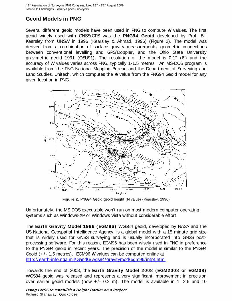
Several different geoid models have been used in PNG to compute N values. The firstgeoid widely used with GNSS/GPS was the PNG94 Geoid developed by Prof. BillKearsley from UNSW in 1996 (Kearsley & Ahmad, 1996) (Figure 2). The model wasderived from a combination of surface gravity measurements, geometric connectionsbetween conventional levelling and GPS/Doppler, and the Ohio State Universitygravimetric geoid 1991 (OSU91). The resolution of the model is 0.1° (6’) and theaccuracy of N values varies across PNG, typically 1-1.5 metres. An MS-DOS program isavailable from the PNG National Mapping Bureau and the Department of Surveying andLand Studies, Unitech, which computes the N value from the PNG94 Geoid model for anygiven location in PNG.
Figure 2. PNG94 Geoid geoid height (N value) (Kearsley, 1996)
Unfortunately, the MS-DOS executable won’t run on most modern computer operatingsystems such as Windows-XP or Windows Vista without considerable effort.
The Earth Gravity Model 1996 (EGM96) WGS84 geoid, developed by NASA and theUS National Geospatial Intelligence Agency, is a global model with a 15 minute grid sizethat is widely used for GNSS surveying and is usually incorporated into GNSS post-processing software. For this reason, EGM96 has been wisely used in PNG in preferenceto the PNG94 geoid in recent years. The precision of the model is similar to the PNG94Geoid (+/- 1.5 metres). EGM96 N values can be computed online athttp://earth-info.nga.mil/GandG/wgs84/gravitymod/egm96/intpt.html
Towards the end of 2008, the Earth Gravity Model 2008 (EGM2008 or EGM08)WGS84 geoid was released and represents a very significant improvement in precisionover earlier geoid models (now +/- 0.2 m). The model is available in 1, 2.5 and 10
43rd Association of Surveyors PNG Congress, Lae, 12th - 15th August 2009Focus On Challenges; Society-Space-Surveyors
Using GNSS to establish a Height Datum on a ProjectRichard Stanaway, Quickclose
minute grid sizes. EGM2008 is gradually being implemented in GNSS post-processingsoftware and most software providers have an EGM08 geoid file which can bedownloaded and setup within an existing configuration. At present, there is no onlinecalculator like there is for EGM96, however Hans-Gerd Duenck-Kerst of Brothersoft hasreleased a free program AllTrans EGM2008 which can be downloaded athttp://www.brothersoft.com/alltrans-egm2008-calculator-216023.html
The default AllTrans installation comes with a 10’ grid file, however if possible, the 2.5’ or1’ files should be downloaded and used with AllTrans to obtain more accurateinterpolations. For most surveying purposes the 2.5’ grid should be sufficiently accurate.as the 1’ file is over 150MB in size and requires a good internet connection to download.
More information on EGM2008 and downloadable EGM2008 grid files can be found athttp://earth-info.nga.mil/GandG/wgs84/gravitymod/egm2008/egm08_wgs84.html
Provided that EGM96 hasn’t been already established as a project geoid model, it isadvisable to use the EGM2008 model where possible. EGM2008 was tested in May 2009in the north of PNG and like EGM96 there is a 1.4-1.5m offset from true MSL. This offsetneeds to be determined in order for more precise MSL estimates to be made using themodel. This process is discussed in more detail later in the paper.
The OmniStar geoid model
Users of OmniStar, especially the HP service, need to be very careful how they interpretelevations from the service through client software such as SoloField. By default, theservice provides MSL estimated from a very inaccurate geoid model used by the receiversoftware, with model inaccuracies exceeding 18 metres in many parts of PNG. Unlessthe user software allows the user to configure and use a proper geoid model such asEGM96, then elevations should be considered to be approximations only (even if thedisplayed precision is less than a metre). To overcome this problem, ellipsoidal heightsshould be logged (by turning the Add GGA-separation setting on) and the ellipsoidheights manually converted to MSL using a separate geoid model program or the EGM96online calculator.
Establishing a height datum on a new project
In situations where there is no existing height control on a project, a new height datumpoint will have to be established within the project area. Either a true MSL datum, or anapproximate MSL datum derived from a geoid model can be used to define the heightdatum. A true MSL height datum should be used if any coastal or river engineering worksmay be associated with the project in the future. If this isn’t the case, then a geoid modelderived MSL datum can suffice. If a true MSL is required, refer to sections later in thepaper which describe this process in more detail.
To establish a new height datum just using a geoid model, 2-3 days of good quality dual-frequency GNSS observations are required on the datum point. The data from theseobservations can then be processed using AUSPOS or NRCan post-processing services toobtain a centimetre accurate ellispsoidal height. The approximate MSL value is thencomputed using the N value derived from a geoid model using equation (2).
43rd Association of Surveyors PNG Congress, Lae, 12th - 15th August 2009Focus On Challenges; Society-Space-Surveyors
Using GNSS to establish a Height Datum on a ProjectRichard Stanaway, Quickclose
Alternatively, if a PNG94 control point is located within 20 -30 km of the new station,then the baseline between the two stations can be observed using Static observationsand then post-processed and the ellipsoid height computed this way. Using an arbitrarydatum (e.g. from a handheld GPS, or from interpolating map contours) is stronglydiscouraged.
Using GNSS on projects with a pre-existing height datum
There are many instances in PNG where MSL Reduced levels have been derived frommore imprecise methods such as trigonometric heighting and barometric altimetry.Trigonometric heighting was often computed from single ray observations with anassumed refraction index, or indeed no correction at all. This has resulted indiscrepancies of up to 5 metres in the realisation of MSL in PNG. The discrepancies areparticularly noticeable in inland areas such as the Highlands.
Surveyors using GNSS techniques on existing projects are usually required to continueproviding elevations with respect to the existing height datum to their clients. Changing aheight datum (even if to a more accurate one) is not to be undertaken lightly, unlessthere are serious problems with it. It is unlikely that any project manager would agree toa change in height datum, as the ramifications are usually very serious if the differencesbetween the two datums is large, the tolerances small, and one datum is mistaken foranother. In these instances the offset between the geoid model used and the existingheight datum may need to be determined. In most projects in PNG, the geoid gradient isan acceptable representation of the local gravity field, so that the local height datumoffset can be used in conjunction with a geoid model over quite large projects.
Computing the local height datum offset from a geoid model
The local height datum offset (o ) can be computed using equation (3) if the ellipsoidheight (h), the existing RL (RLLOCAL) of the datum station and N values are known:
o = RLLOCAL - h + N (3)
Once the offset is computed, reduced levels in the local height datum can then becomputed from the geoid model using equation (4).
RLLOCAL = h - N + o (4)
Alternatively, if the ellipsoidal height for the existing height datum station is unknown,irrelevant, or to simplify RTK survey workflows, a false ellipsoid height (hFALSE) can becomputed and used in the system using equation (5).
hFALSE = RLLOCAL + N (5)
43rd Association of Surveyors PNG Congress, Lae, 12th - 15th August 2009Focus On Challenges; Society-Space-Surveyors
Using GNSS to establish a Height Datum on a ProjectRichard Stanaway, Quickclose
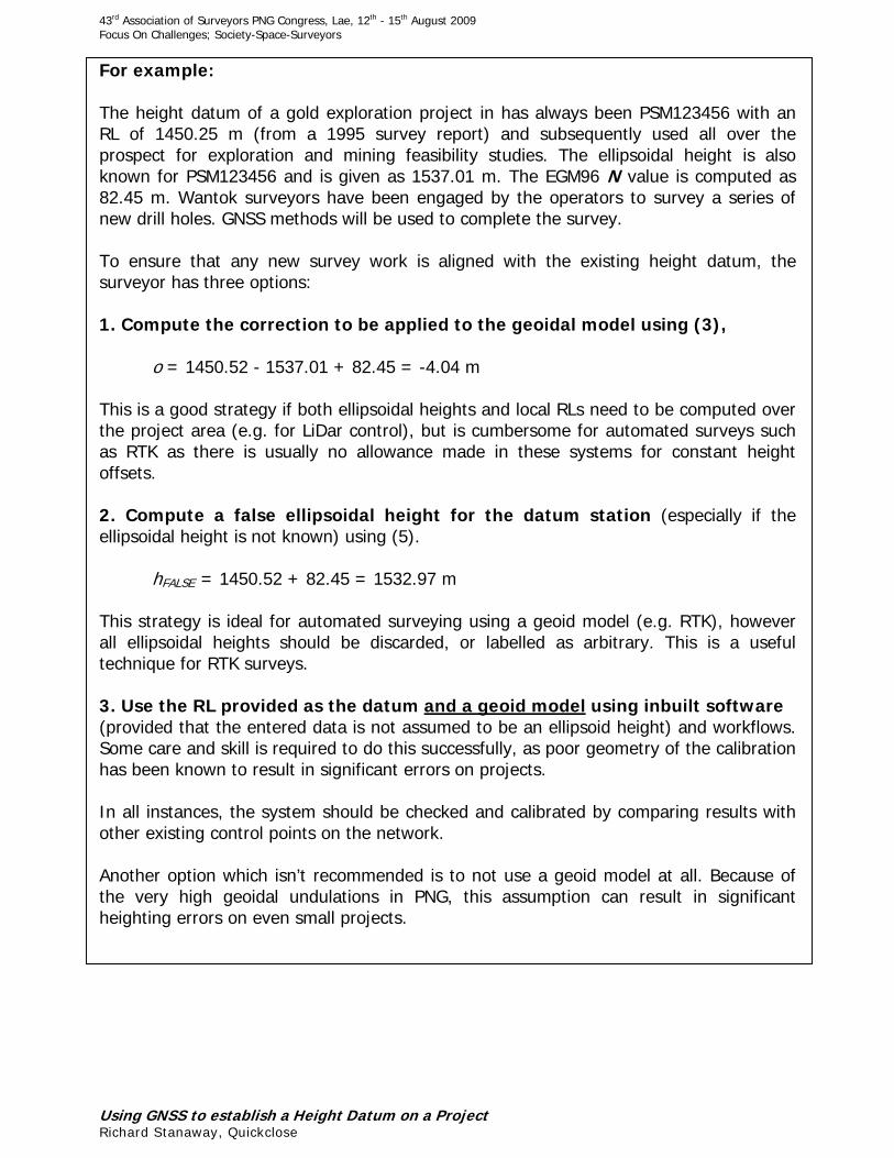
For example:
The height datum of a gold exploration project in has always been PSM123456 with anRL of 1450.25 m (from a 1995 survey report) and subsequently used all over theprospect for exploration and mining feasibility studies. The ellipsoidal height is alsoknown for PSM123456 and is given as 1537.01 m. The EGM96 N value is computed as82.45 m. Wantok surveyors have been engaged by the operators to survey a series ofnew drill holes. GNSS methods will be used to complete the survey.
To ensure that any new survey work is aligned with the existing height datum, thesurveyor has three options:
1. Compute the correction to be applied to the geoidal model using (3),
o = 1450.52 - 1537.01 + 82.45 = -4.04 m
This is a good strategy if both ellipsoidal heights and local RLs need to be computed overthe project area (e.g. for LiDar control), but is cumbersome for automated surveys suchas RTK as there is usually no allowance made in these systems for constant heightoffsets.
2. Compute a false ellipsoidal height for the datum station (especially if theellipsoidal height is not known) using (5).
hFALSE = 1450.52 + 82.45 = 1532.97 m
This strategy is ideal for automated surveying using a geoid model (e.g. RTK), howeverall ellipsoidal heights should be discarded, or labelled as arbitrary. This is a usefultechnique for RTK surveys.
3. Use the RL provided as the datum and a geoid model using inbuilt software(provided that the entered data is not assumed to be an ellipsoid height) and workflows.Some care and skill is required to do this successfully, as poor geometry of the calibrationhas been known to result in significant errors on projects.
In all instances, the system should be checked and calibrated by comparing results withother existing control points on the network.
Another option which isn’t recommended is to not use a geoid model at all. Because ofthe very high geoidal undulations in PNG, this assumption can result in significantheighting errors on even small projects.

43rd Association of Surveyors PNG Congress, Lae, 12th - 15th August 2009Focus On Challenges; Society-Space-Surveyors
Using GNSS to establish a Height Datum on a ProjectRichard Stanaway, Quickclose
Establishing an MSL datum from Tidal Observations.
Tidal height datums are usually established using measurements from a speciallyconstructed tide gauge. MSL is computed by modelling the tide gauge measurementsover a considerable period of time, from months to years. MSL is generally defined asbeing approximately halfway between the Lowest Astronomical Tide (LAT) and HighestAstronomical Tide (HAT). These are the lowest and highest tides than can be expectedover a full range of lunar and solar configurations (over a 19 year Metonic cycle). Accessto a rigorous tidal datum isn’t always possible, so this paper describes a rudimentarymethod for surveyors to measure tides in a local project area in order to estimate MSLwith a precision of 10 cm.
Where a project height datum is required to be aligned with true Mean Sea Level (MSL),or Lowest Astronomical Tide (LAT), for example for coastal engineering, construction, orbathymetric surveys, it is necessary to measure sea level from a benchmark in a locationclose to the project area.
Location of tidal monitoring station considerations
Sea level should be measured at a location where wave amplitudes are reduced.Sheltered bays and harbours are ideal. River mouths should be avoided as high riverflows adversely affect sea level measurements. Solid wharves and jetties (preferablyconcrete, or pile driven) provide reasonably stable locations for temporary benchmarksfrom which direct sea level observations can be made. If a wharf or jetty is used, it isadvisable to locate benchmarks away from where boats and ships will be berthed.
The monitoring benchmark network
Wharves and jetties may be subject to localised subsidence or disturbance over longerperiods of time, so a local benchmark network should be established within 1-2 km ofwhere the tidal monitoring will be undertaken, to provide redundancy and to monitorstability of the network.
The following marks should constitute the network (Figure 3):
A secure GNSS benchmark, or CORS station (a stable monument with good skyvisibility in a secure location such as a government, company or hotel compound) shouldbe established within 5 km of the tidal monitoring location. This is used to get 3 or moredays of GNSS base data (72 hours or more observations) in order to estimate the ITRFabsolute ellipsoidal height for the mark.
A bedrock benchmark or other highly stable monument that isn’t sensitive to localisedsubsidence due to ground water changes and landslips. This station is used to verify thestability of the primary GNSS base station, particularly if the GNSS antenna is onpotentially unstable ground, or built on clay soils subject to seasonal variations in height.

43rd Association of Surveyors PNG Congress, Lae, 12th - 15th August 2009Focus On Challenges; Society-Space-Surveyors
Using GNSS to establish a Height Datum on a ProjectRichard Stanaway, Quickclose
Secondary benchmarks near the monitoring benchmark. Ideally two, preferably threebenchmarks in stable locations within 100 metres of the monitoring benchmark (Figure5). These are used to verify local stability by means of conventional levelling. One of thebenchmarks should be a PSM and have good sky visibility for GNSS observations.
The tidal monitoring benchmark should be at a location where a levelling staff can belowered directly to the sea surface and measurements read off the staff (i.e. the edge ofa jetty, wharf or pier, Figure 4). Alternatively, it can also be a benchmark from whichdirect readings can be made to the sea surface by conventional levelling using rise/fall orheight of collimation methods.
Figure 3. A typical PNG tidal BM network (Aitape, Sandaun Province)

43rd Association of Surveyors PNG Congress, Lae, 12th - 15th August 2009Focus On Challenges; Society-Space-Surveyors
Using GNSS to establish a Height Datum on a ProjectRichard Stanaway, Quickclose
Figure 4. Local BM network (left) and monitoring BM (right)
Procedure for measuring and modelling local tides
Tidal Predictions
The first step is to obtain tidal predictions for the site. This is necessary in the most usualcase where tides cannot be measured over a tidal season. Michael Hopper has developeda free software program WZTide32 to compute tidal predictions. The software can bedownloaded at http://www.wxtide32.com
Once the software has been installed and is running, select the location for the tidalprediction: (File, Location). If the location to be monitored isn’t in the location table, thecoordinates of the tidal monitoring point can be entered manually (File, User station). Togenerate a tidal calendar showing times and heights of Low and High tides:select (File, Tide Calendar) and select the start date from the calendar. A monthly tidaltable is generated showing times (in PNG Time) and predicted heights (sea levels on theprediction datum) of Low and High Tides. Other useful information shown at the top ofthe table include the predicted Historical Low and High levels which broadly speakingequate to Lowest Astronomical Tide (LAT) and Highest Astronomical Tide (HAT).
For each day of monitoring, WxTide can compute incremental predictions (e.g. every 30minutes) (File, Incremental Tides) and select the date. Predicted sea levels above theprediction datum are shown in tabular format. This table can be printed off and used as alog sheet for tidal measurements.

43rd Association of Surveyors PNG Congress, Lae, 12th - 15th August 2009Focus On Challenges; Society-Space-Surveyors
Using GNSS to establish a Height Datum on a ProjectRichard Stanaway, Quickclose
Tidal measurements
Measurements of sea level should be made sothat they can be related to the incremental tidalpredictions (i.e. on the hour, or 30 minutes pastthe hour). It is important to get measurementsbefore and after High and Low tides, to capturethe full scale of each tidal cycle, howevermeasurements should be made as often aspracticable. The more measurements that aremade the better the MSL estimation will be. Ingeneral, seas are calmer in the early morningand late evening.
Even during calm periods, there will inevitably besome wave action. Several readings should beaveraged to get a single observation(e.g. 3 wave crests and 3 wave troughs)(Figure 5).
Figure 5. Staff Readings for sea level measurements
43rd Association of Surveyors PNG Congress, Lae, 12th - 15th August 2009Focus On Challenges; Society-Space-Surveyors
Using GNSS to establish a Height Datum on a ProjectRichard Stanaway, Quickclose
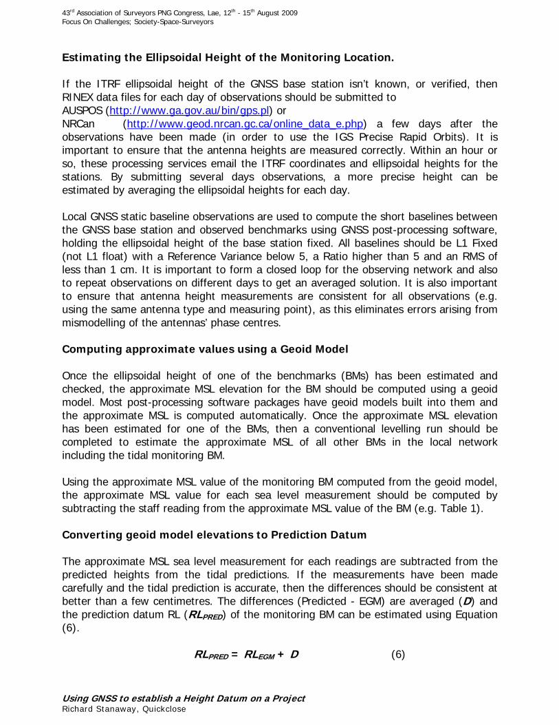
Estimating the Ellipsoidal Height of the Monitoring Location.
If the ITRF ellipsoidal height of the GNSS base station isn’t known, or verified, thenRINEX data files for each day of observations should be submitted toAUSPOS (http://www.ga.gov.au/bin/gps.pl) orNRCan (http://www.geod.nrcan.gc.ca/online_data_e.php) a few days after theobservations have been made (in order to use the IGS Precise Rapid Orbits). It isimportant to ensure that the antenna heights are measured correctly. Within an hour orso, these processing services email the ITRF coordinates and ellipsoidal heights for thestations. By submitting several days observations, a more precise height can beestimated by averaging the ellipsoidal heights for each day.
Local GNSS static baseline observations are used to compute the short baselines betweenthe GNSS base station and observed benchmarks using GNSS post-processing software,holding the ellipsoidal height of the base station fixed. All baselines should be L1 Fixed(not L1 float) with a Reference Variance below 5, a Ratio higher than 5 and an RMS ofless than 1 cm. It is important to form a closed loop for the observing network and alsoto repeat observations on different days to get an averaged solution. It is also importantto ensure that antenna height measurements are consistent for all observations (e.g.using the same antenna type and measuring point), as this eliminates errors arising frommismodelling of the antennas’ phase centres.
Computing approximate values using a Geoid Model
Once the ellipsoidal height of one of the benchmarks (BMs) has been estimated andchecked, the approximate MSL elevation for the BM should be computed using a geoidmodel. Most post-processing software packages have geoid models built into them andthe approximate MSL is computed automatically. Once the approximate MSL elevationhas been estimated for one of the BMs, then a conventional levelling run should becompleted to estimate the approximate MSL of all other BMs in the local networkincluding the tidal monitoring BM.
Using the approximate MSL value of the monitoring BM computed from the geoid model,the approximate MSL value for each sea level measurement should be computed bysubtracting the staff reading from the approximate MSL value of the BM (e.g. Table 1).
Converting geoid model elevations to Prediction Datum
The approximate MSL sea level measurement for each readings are subtracted from thepredicted heights from the tidal predictions. If the measurements have been madecarefully and the tidal prediction is accurate, then the differences should be consistent atbetter than a few centimetres. The differences (Predicted - EGM) are averaged (D) andthe prediction datum RL (RLPRED) of the monitoring BM can be estimated using Equation(6).
RLPRED = RLEGM + D (6)
43rd Association of Surveyors PNG Congress, Lae, 12th - 15th August 2009Focus On Challenges; Society-Space-Surveyors
Using GNSS to establish a Height Datum on a ProjectRichard Stanaway, Quickclose
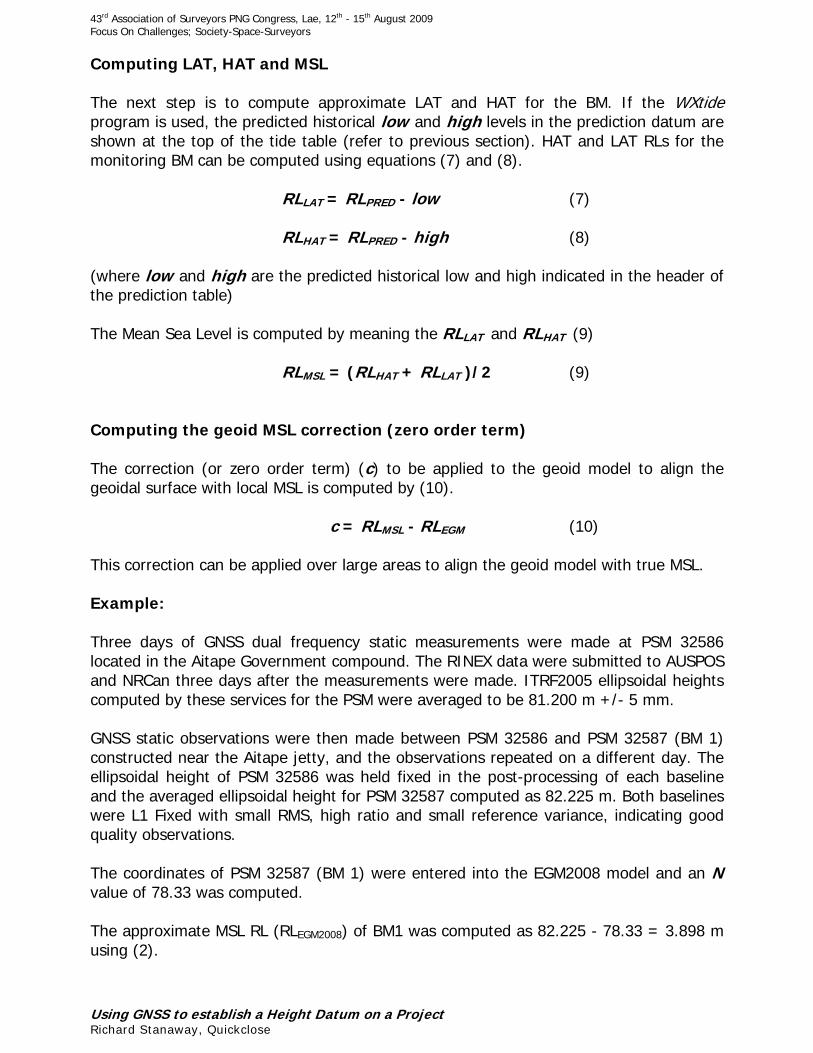
Computing LAT, HAT and MSL
The next step is to compute approximate LAT and HAT for the BM. If the WXtideprogram is used, the predicted historical low and high levels in the prediction datum areshown at the top of the tide table (refer to previous section). HAT and LAT RLs for themonitoring BM can be computed using equations (7) and (8).
RLLAT = RLPRED - low (7)
RLHAT = RLPRED - high (8)
(where low and high are the predicted historical low and high indicated in the header ofthe prediction table)
The Mean Sea Level is computed by meaning the RLLAT and RLHAT (9)
RLMSL = (RLHAT + RLLAT )/2 (9)
Computing the geoid MSL correction (zero order term)
The correction (or zero order term) (c) to be applied to the geoid model to align thegeoidal surface with local MSL is computed by (10).
c = RLMSL - RLEGM (10)
This correction can be applied over large areas to align the geoid model with true MSL.
Example:
Three days of GNSS dual frequency static measurements were made at PSM 32586located in the Aitape Government compound. The RINEX data were submitted to AUSPOSand NRCan three days after the measurements were made. ITRF2005 ellipsoidal heightscomputed by these services for the PSM were averaged to be 81.200 m +/- 5 mm.
GNSS static observations were then made between PSM 32586 and PSM 32587 (BM 1)constructed near the Aitape jetty, and the observations repeated on a different day. Theellipsoidal height of PSM 32586 was held fixed in the post-processing of each baselineand the averaged ellipsoidal height for PSM 32587 computed as 82.225 m. Both baselineswere L1 Fixed with small RMS, high ratio and small reference variance, indicating goodquality observations.
The coordinates of PSM 32587 (BM 1) were entered into the EGM2008 model and an Nvalue of 78.33 was computed.
The approximate MSL RL (RLEGM2008) of BM1 was computed as 82.225 - 78.33 = 3.898 musing (2).
43rd Association of Surveyors PNG Congress, Lae, 12th - 15th August 2009Focus On Challenges; Society-Space-Surveyors
Using GNSS to establish a Height Datum on a ProjectRichard Stanaway, Quickclose
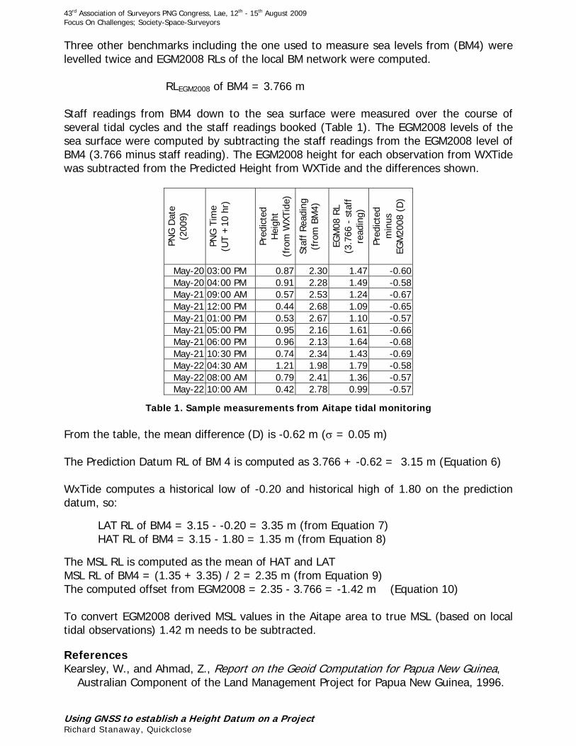
Three other benchmarks including the one used to measure sea levels from (BM4) werelevelled twice and EGM2008 RLs of the local BM network were computed.
RLEGM2008 of BM4 = 3.766 m
Staff readings from BM4 down to the sea surface were measured over the course ofseveral tidal cycles and the staff readings booked (Table 1). The EGM2008 levels of thesea surface were computed by subtracting the staff readings from the EGM2008 level ofBM4 (3.766 minus staff reading). The EGM2008 height for each observation from WXTidewas subtracted from the Predicted Height from WXTide and the differences shown.
PNG
Dat
e(2
009)
PNG
Tim
e(U
T +
10 h
r)
Pred
icte
dH
eigh
t(f
rom
WXT
ide)
Staf
f Rea
ding
(fro
m B
M4)
EGM
08 R
L(3
.766
- s
taff
read
ing)
Pred
icte
dm
inus
EGM
2008
(D
)
May-20 03:00 PM 0.87 2.30 1.47 -0.60May-20 04:00 PM 0.91 2.28 1.49 -0.58May-21 09:00 AM 0.57 2.53 1.24 -0.67May-21 12:00 PM 0.44 2.68 1.09 -0.65May-21 01:00 PM 0.53 2.67 1.10 -0.57May-21 05:00 PM 0.95 2.16 1.61 -0.66May-21 06:00 PM 0.96 2.13 1.64 -0.68May-21 10:30 PM 0.74 2.34 1.43 -0.69May-22 04:30 AM 1.21 1.98 1.79 -0.58May-22 08:00 AM 0.79 2.41 1.36 -0.57May-22 10:00 AM 0.42 2.78 0.99 -0.57
Table 1. Sample measurements from Aitape tidal monitoring
From the table, the mean difference (D) is -0.62 m ( = 0.05 m)
The Prediction Datum RL of BM 4 is computed as 3.766 + -0.62 = 3.15 m (Equation 6)
WxTide computes a historical low of -0.20 and historical high of 1.80 on the predictiondatum, so:
LAT RL of BM4 = 3.15 - -0.20 = 3.35 m (from Equation 7)HAT RL of BM4 = 3.15 - 1.80 = 1.35 m (from Equation 8)
The MSL RL is computed as the mean of HAT and LATMSL RL of BM4 = (1.35 + 3.35) / 2 = 2.35 m (from Equation 9)The computed offset from EGM2008 = 2.35 - 3.766 = -1.42 m (Equation 10)
To convert EGM2008 derived MSL values in the Aitape area to true MSL (based on localtidal observations) 1.42 m needs to be subtracted.
ReferencesKearsley, W., and Ahmad, Z., Report on the Geoid Computation for Papua New Guinea,
Australian Component of the Land Management Project for Papua New Guinea, 1996.